9 minute read
Optimising LNG installations


Vincent Higelin, Fives Cryomec AG, Switzerland, discusses two factors that should be considered while designing LNG installations with cryogenic pumps.

Most issues that can occur in LNG cryogenic pumps are the result of cavitation, which is primarily caused by an insuffi cient net positive suction head (NPSH) and fl uid shocks. Experience shows that the second factor is due to inadequate pump cool-down procedures and installations.
Understanding these two problems is essential to prevent cryogenic pumps failure and improve their reliability for end users and operators.
Insufficient NPSH

The NPSH is an important topic for cryogenic fl uids, especially LNG, which have boiling points of less than -150˚C.
The NPSH can be defi ned as the difference between the pressure of the liquid gas under normal vapour pressure and the actual pressure at the pump inlet. This difference is the liquid head, less the losses due to heat generated and of pressure through the piping, valves, etc. It often happens that the NPSH available on-site is not suffi cient for the pump to operate. In summary: NPSH(a) = subcooling of the liquid which is provided for the pumping system (a = available). NPSH(r) = necessary subcooling that a pump needs to prevent any cavitation (r = required).

Both cavitation and fl uid shocks can be direct evidence of a lack of NPSH at the pump inlet. Consequently, the higher the NPSH requested by the pump is, the higher the risk of cavitation problems (which affect the lifetime of the pump) and fl uids shocks when the pump is rotating at high speeds with the presence of gas bubbles. These fl uid shocks can cause shaft deformation and failure as well as impeller damage. These problems are particularly dangerous when the pump is used for LNG applications.
In short, cryogenic pumps can normally work only when the NPSH is suffi cient. When there is a lack of NPSH at the pump
inlet, cavitation will become evident and a distinctive noise will be heard. This noise increases when cavitation gets stronger. In general, this noise is also accompanied by vibrations, which tend to unbalance the shaft and cause faster wear and tear on parts, including motor bearings.
Therefore, cavitation can also have other immediate negative consequences on pumps, such as vibration and instability.
Va
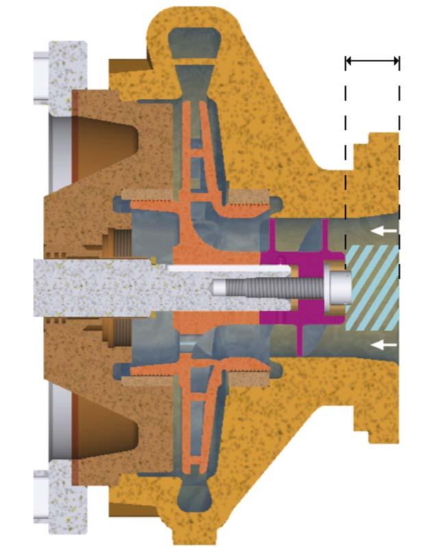
Figure 1. Standard inducer.

Vb
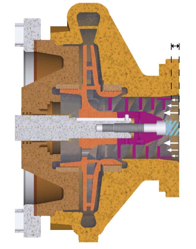
Figure 2. Cryomec® Supercharger. How to decrease the NPSH requested by a pump

The fi rst step is to install a standard inducer at the suction, which will improve the velocity distribution to the impeller. The conventional inducer will improve the NPSH(r) of the pump by about half, but for some applications, such as distribution and process pumps, this device is not suffi cient to provide adequate protection against cavitation, loss of prime, and fl uid shocks.
Fives Cryomec AG’s Cryomec® Supercharger helps to bring NPSH(r) close to 0. This has been achieved following intensive hydraulic research and testing with liquid nitrogen. The technology provides a velocity distribution that remains constant with practically no turbulence. The fl ow changes direction due to centrifugal forces and moves smoothly through the spiral channels of the Cryomec® Supercharger. This is different from using a conventional inducer where the pumped liquid suffers turbulence (which may lead to gas bubbles in front of the pump).
A standard inducer is shown in Figure 1. Under cavitation condition, the gas bubbles are accumulating at the front of the inducer (turbulence area in light blue) as the cross-section area of fl ow is reduced (white arrow). In front of the inducer, the volume (Va) is large between the pump suction fl ange and the inducer, thus reducing the NPSH(a). As cryogenic pumps cannot be operated under cavitation, there will be a premature wear on the pump parts.
Under the same condition, if the pump is equipped with the Cryomec® Supercharger (Figure 2), it allows a better aspiration towards the impeller as the fl ow is continuously aspirated into it (larger cross-section area of fl ow: white arrow). The conical shape optimises the fl ow direction and head losses are reduced within this technology compared with the inducer. Moreover, as the ‘dead’ volume (Vb) in front of the Cryomec® Supercharger is signifi cantly reduced, there is no accumulation at the front of the device.
Thanks to this device, which is available for single-stage pumps, priming is easier, and the pump lifetime will be enhanced.
Moreover, it helps to reduce installation costs as elevated tanks are not required.
To conclude, the NPSH(a) (available from the tank for the pump) must be present inside the inducer and impeller: [NPSH(a) > NPSH(r)] both before the pump start and during the pump priming. In addition, it must always be kept for a smooth running.
Pumps for cryogenic liquids, especially LNG pumps, are generally considered to be delicate to operate, and an effi cient cool-down requires detailed and critical procedures.
Pump failures due to the cool-down procedure can lead to major problems and cause safety concerns for end users and operators. There are various points associated with the piping design and operation of cryogenic pumps. Therefore, it is important to check the following parameters: What is the length of the suction line to the tank?
Is the return gas line connected upwards to the tank without syphon? Is there piping stress in hot or cold conditions? Is there enough slope for the suction vent and bypass lines? Is the minimum pump cool-down time followed, including the entire suction line cool-down?
Best practices to minimise risks of pump failures: configuring the lines
In any case, it is important to properly cool-down the cryogenic pump before start-up with the best confi guration for the lines.
The suction line is of particular importance as it is the most frequent cause of priming and pumping diffi culties. The suction line must never be horizontal. It must always have a continuous slope, either upward or downward from the storage tank to the pump, with the pump located as near to the supply tank as possible.
The line size is also important. A line that is too small will create excessive friction loss, while a line that is too large will unnecessarily increase the heat inleak. The suction line must be as short as possible, well insulated, and sharp bends should be avoided. On the contrary, its diameter should be as big as the pump inlet, or slightly bigger. A strainer or fi lter should also always be used in the suction line to ensure an extended pump lifecycle and to minimise the danger of accidents due to contamination, particularly in LNG systems. Additionally, the suction line must be equipped with a pressure relief valve (safety valve) to prevent any possible damage to the pump and its shaft sealing system, due to excessive suction pressure. It is important to ensure that all piping lines are adequately supported, and it is essential to install compensators or fl exible lines at the pump fl anges.
The bypass and return gas lines must never be horizontal or have a downward slope. They should always have a continuous upward slope from the pump so that there can never be any low points in which gas can be trapped and create a liquid lock.

Figure 3. Example of an LNG loading system with manual valves.
Figure 4. Example of a Cryomec VSMP with the three-way valve (PV 20).

The ideal slope for these lines is approximately 100% (45˚) with 10% (approximately 5˚) recommended as minimum.
Piping stress can be avoided or reduced through the installation of fi x points. A pipe fi xed point is a very rigid support (without any elasticity) blocking the pipe in the three axes (clamping capable of sliding on the pipe is forbidden).
Case study
As mentioned previously, experience shows that the majority of problems are caused by an inadequate pump cool-down procedure and, sometimes, by operators failing to ensure that the pump has been fully primed.
For this reason, systems that automate the pump cool-down priming have huge operational advantages, especially if such systems are competitive compared to an installation designed for manual operation.
Fives Cryomec AG has developed a system incorporating an optimised three-way valve, which operates automatically. This valve is directly mounted on a skid after the pump outlet.
Figure 3 shows an example of an LNG loading system with manual valves. Prior to start-up, it is important to check that the discharge valve 7 on the discharge line is completely closed and reduce the opening of the bypass valve 10, so that during start-up the pump is at minimum fl ow and not at full
fl ow.
When the pump has started up, it is mandatory to regulate the discharge pressure to the value required by adjusting the bypass valve 10.
Once the pump fl ow rate has been established, the fl ow is switched to the delivery line by opening the discharge valve 7, while at the same time closing the bypass valve 10.
The opening and the closing of valves on a cryogenic centrifugal pump installation must always be slow and gradual (approximately 5 sec.).
Figure 4 presents an example of an LNG loading system with the three-way valve (PV 20). The discharge valve 7 and the bypass valve 10 are replaced by one single pneumatic valve, PV 20, which is automatically controlled by the temperature sensor TE3 (PT100 used for cool-down supervision).
To conclude, the manual operation of discharge and bypass valves for pump cool-down and priming is eliminated, which avoids any possibility of abnormal pump failure due to an operator’s error.
Conclusion
The elements detailed in the article show that many parameters have to be taken into account to avoid premature wear, gas development, instability, and vibrations in cryogenic pumps, especially for LNG applications.
The Cryomec® Supercharger developed by Fives Cryomec AG, Fives a Group subsidiary specialised in the design, manufacture, and maintenance of cryogenic pumps, has proven reliable to ensure safe functioning of the pump for operators and end users alike.
Page Number | Advertiser 04| Berndorf Band Engineering GmbH IFC| Chart Industries 59| Elliott Group 41| Gastech 2021 46| Global Energy Show 55| GPA Midstream Convention 37| Hallwood Modular 02| Hitard Engineering
OFC & 35| IPCO 53| John Zink Hamworthy Combustion

AD INDEX
23| Koch-Glitsch 27| Kurita Europe GmbH 13| Merichem Company 50 & 56| Palladian Publications 18| Rembe® GmbH Safety + Control 32| Selective Adsorption Associates, Inc. 07| Shell Catalysts & Technologies 21| Siemens 08 - 09| Sulzer
IBC| VA TECH WABAG Ltd
OBC| Yokogawa


