8 minute read
Embracing biology


Helma Hakala, VA TECH WABAG GmbH, introduces an innovative biological process for produced water treatment in Romania.


For oil production, the treatment of produced water has a large infl uence on the level of environmental protection and economic success. The treatment employed should utilise sophisticated technology that is able to cope with well characteristics that can vary signifi cantly from borehole to borehole. WABAG has built a new produced water treatment plant in
Romania. Due to specifi c oil extraction processes, the produced water contains large quantities of non-biodegradable organic compounds. Therefore, an innovative process was developed for the specifi c requirements of the oilfi eld. The design includes physical/chemical and biological process steps, as well as advanced fi ltration and adsorption technologies, which represents a fi rst in this specifi c fi eld. This advanced, multi-stage treatment process was tested successfully on the spot over several months, and the plant was commissioned in 2017.

Produced water

A major factor in the economic success of oilfi elds is the treatment of the large quantities of water emanating from production. Every barrel of oil that is pumped is accompanied by six to eight barrels of produced water. It is the largest waste stream generated in the oil and gas industry, and consists of a mixture of different compounds, both organic and inorganic.
The priority of the project in Romania was the reduction of pollutants in the produced water to produce a more environmentally friendly discharge. The main issue was the elimination of non-degradable chemical oxygen demand (COD). For this reason, adsorption using activated carbon technology was implemented which proved to be successful.
A three-stage treatment system has been installed comprising a physical-chemical stage, an innovative combination of biological treatment, and adsorption using activated carbon. By incorporating this, the plant effectively decreased the COD in the produced water by 92% to 95%.
New process design
Based on the specifi c average and maximum values of the incoming water (Figure 1) and the discharge limits imposed on the river, the following concept has been developed for produced water treatment.
The main units in the treatment plant design consist of: Two inlet tanks for buffering and equalisation of flow and loads and for oil removal. Two dissolved air flotation units for the removal of suspended solids and oil after adding coagulants and flocculants. Cooling towers for cooling water. Two activated sludge tanks designed as aerobic tanks. Two clarifiers for settling the mixed liquor.

Table 1. The produced water raw composition and maximum limits to the river
Serial number Parameter Unit Average values of incoming water Maximum discharge limit for the river
1 pH °C 7 – 8.5 6.5 – 8.5 2 Temperature Bar 43 35 3 Pressure mg/l 1 4 Total suspended solids (TSS) mg/l ≤400 35 5 Petroleum products TPH mg/l 350 5 6 Total nitrogen (TKN) mg/l 8 15 7 NH4 mg/l 1.4 3 8 COD mg/l 870 125 9 BOD5 mg/l 330 25 10 Total phosphorus mg/l 0.27 2 11 Filtered residue mg/l 1152 2000 12 Chlorides mg/l 231 500 13 Dry filterable residue mg/l 1766
14 Detergents mg/l 0.64 0.5 15 Phenol index mg/l ≤7 0.3 16 TOC mg/l 320 17 SiO2 mg/l 78 18 Alkalinity mEch/l 14.84 0.1 19 Turbidity NTU 250 0.2 20 Substances extracted with perchlorethylene mg/l 1.340 25 Four dual media filters for the removal of the remaining suspended solids. 12 activated carbon filters for the final polishing required in order to reach the target COD concentration. One sludge storage. Two sludge dewatering centrifuges.
Table 1 shows the produced water raw composition and maximum limits to the river.
Treatment processes and performance
The treatment plant was designed for a daily average produced water fl ow of 8000 m3, using an overdesign factor of 10%, which results in a maximum inlet fl ow of 366 m3/h. The sequence of process units are as per the process fl ow diagram in Figure 1.
Inlet tanks
Two inlet tanks have been designed, each with a total usable volume of 1600 m3 where oil-water separation and solids settling take place owing to density differences and the hydraulic retention time of more than 4 hours. The separated oil is discharged into the slop oil tank (8 m3) and recovered slop oil is transferred to the oil storage facilities. Up to 4000 m3/day can be re-injected into the water disposal reservoir for emergency measures.
Chemical treatment and dissolved air flotation
The physical chemical stage (two lines) consists of a coagulation tank, a fl occulation tank, and a dissolved air fl otation (DAF) unit (including its own internal recirculation system). A mix of the inlet tank effl uent, internal recycled used water and polluted rainwater, in addition to the excess sludge from the activated sludge tanks, are treated and directed to the inlet tanks. In order to improve suspended solid and hydrocarbon separation,

Figure 1. Process flow diagram.
coagulants and fl occulants are mixed with the produced water stream. The separation process in the DAF unit is enhanced by recirculation and compressed air dissolution. Figure 2 shows the quality of produced water before and after chemical treatment.
Inlet pumping station and cooling system
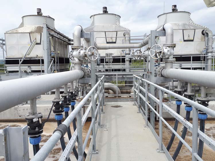
After the DAF unit, the temperature level of the produced water is approximately 55°C. In order to cool down the water to an appropriate maximum temperature of 35°C in the activated sludge tanks for biological treatment, the inlet pumping station pumps a partial stream of the produced water into the cooling system, which accordingly reduces the temperature in the tanks if it is >35°C (measured online). The cooling system consists of three cooling towers with enhanced airfl ow for maximum effi ciency during the summer.
Activated sludge system
For biological treatment, it was additionally decided to remove carbon concentrations by means of specifi cally adapted microorganisms.
The variations in loading have a resultant effect upon the process air, optional nitrogen nutrient dosing, and the simultaneous nitrifi cation/denitrifi cation requirement. In case of insuffi cient availability of nutrients for biomass growth, the dosing of urea as a source of nitrogen and phosphoric acid for phosphorus can create adequate biomass living conditions.
Clarification
Following biological treatment, the produced water fl ows by gravity to the downstream clarifi ers. The two rectangular type tanks each have a volume of 480 m3. In order to increase the specifi c settling surface, lamella packages are installed in the clarifi ers. The clarifi ed water is sent upwards to the dual media fi ltration units by the intermediate pumping station.
Dual media filters
Four dual media fi lters are installed upstream of the fi nal granular activated carbon (GAC) treatment step in order to minimise the total suspended solids load. Gravel and anthracite have been chosen as fi lter media as they exhibit excellent separation effi ciency. Each fi lter has a bed volume of 14 m3 .
Activated carbon adsorption
In order to reduce the remaining COD and phenol to the required effl uent limits, an activated carbon adsorption stage has been installed. This system consists of four lines in parallel operation, each of which has three fi lters in series (two actuated, the third in standby mode). Each fi lter has a bed volume of 43 m3 activated carbon.
Sludge treatment
All sludge streams in the produced water treatment plants are collected and thickened in the DAF unit 5%.

Figure 2. View of the cooling towers.

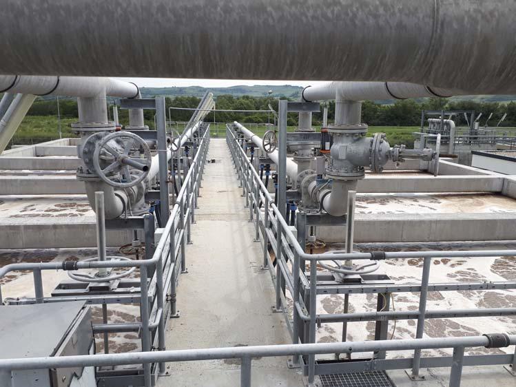
Figure 3. Biological treatment.

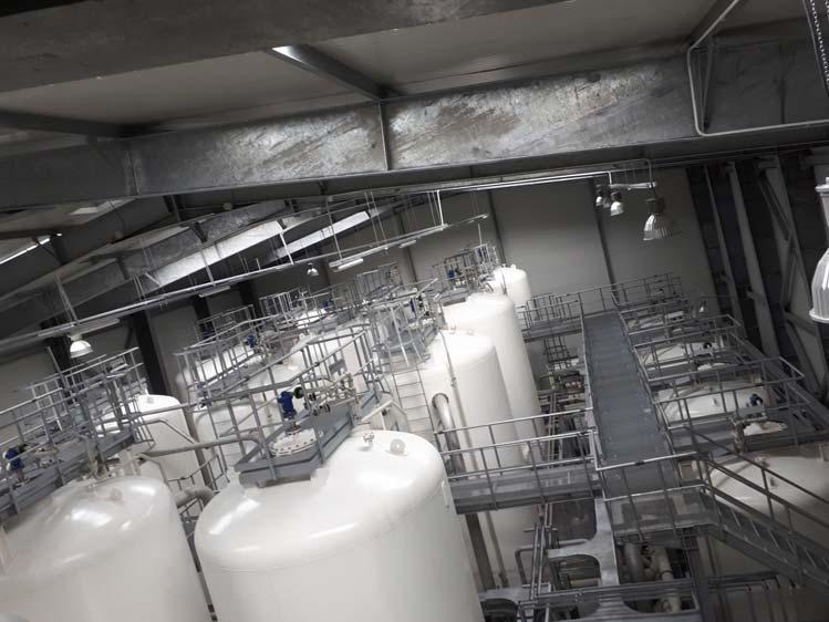
Figure 4. View of the cooling towers.
Table 2. Design parameters for the biological stage
Serial number Parameter Unit Minimum Maximum tender book Pilot tests Design
1 BOD5 mg/l 200 330 200 200 2 TKN mg/l 8 20 14 20 3 NH4 mg/l 1.4 18 14 20
Table 3. Produced water quality before and after GAC filtration
Serial number Parameter Unit Inflow to GAC filtration Outflow of GAC filtration
1 COD mg/l 260 Maximum 125 2 Phenol index mg/l 0.5 Maximum 0.3
From here, the sludge gravitates to the sludge buffer tank with a storage capacity of 2.5 days and a total volume of 200 m3. It is also used as a feed tank for the downstream sludge dewatering by centrifuges. The sludge fi lter cakes have a maximum residual water content of 70% and are disposed at a landfi ll.
Conclusion
The plant treats a maximum of 360 m3/h of wastewater comprising the following main components: Storage and equalisation tanks. Coagulation/flocculation. DAF. Cooling towers (55°C down to 35°C). Biological treatment (activated sludge process). Lamella clarifiers. Flocculation and dual media filtration (DMF). GAC filtration for extended COD removal. Sludge dewatering (two phase centrifuge). Service water station.
WABAG completed the produced water treatment plant in Romania in 2017. Since then, it has been in continual operation and successfully meets all required standards. Therefore, the plant makes a substantial contribution to environmental protection.
The purpose of the related regulations is to protect and enhance the environment to the fullest possible extent both now and for future generations in accordance with the respective Romanian and European regulations. The plant operator is obliged to reduce the levels of water, air, soil, noise, and toxic substance (e.g. sludge) pollution.
The government authorities have drawn up technical standards and environmental regulations, as well as control compliance on site at regular intervals. The GAC technology (fi ltration, loading, unloading) used represents the largest fully automatic system implemented in Romania to date.
Need a reprint?


