8 minute read
Expanding LNG options


Enver Karakas and Stephen Ross, Elliott Group, USA, discuss how the use of cryogenic liquid expanders in gas liquefaction enhances plant efficiency.
Liquefaction is the preferred method for effi cient transport and storage of compressible gases. Storage of LNG requires cooling the gas to cryogenic temperatures under atmospheric pressure. To illustrate the difference liquefaction makes, methane in a liquid state under atmospheric pressure has a density of 428 kg/m3 at a cryogenic temperature of -165°C (-265°F). This is about 600 times greater than methane in a gaseous state under atmospheric conditions (20°C, 1 atm). For a given volume of a storage tank or transportation tanker, this equates to 600 times more mass of methane.
High-pressure liquefi ed gas was conventionally expanded using a Joule-Thomson (JT) throttling valve to reduce the fl uid pressure to an acceptable level. Replacing the traditional JT valve with a cryogenic liquid expander can increase LNG production. For this reason, cryogenic liquid expanders are an important part of every new LNG liquefaction plant, and are widely used in single-phase


applications to enhance the overall effi ciency of the LNG liquefaction process.
Background
In principle, gas liquefaction is a refrigeration process based on the Carnot cycle, fi rst described by French physicist Sadi Carnot in 1824. Carnot discovered that the effi ciency of a heat engine depends upon its input and output temperatures. The lower the fi nal resultant temperature, the lower the Carnot effi ciency will be, as more energy input is necessary to achieve the end temperature. Consequently, more energy input is required to reduce the temperature of a fl uid by one degree at a relatively lower temperature than is required to achieve the same reduction at a relatively higher temperature. When applied to a gas liquefaction process, the Carnot effi ciency of the process is proportionally lower for fl uids having a lower liquefaction temperature since more energy input is required.
In 1895, German engineer Carl von Linde invented the fi rst continuous process for gas liquefaction. This process was based on repeating the cycles of gas compression, pre-cooling of the compressed gas in a heat exchanger, and expansion of the compressed pre-cooled gas across a JT throttling valve. This process yields the desired result, but unfortunately consumes a high amount of energy, making it commercially unattractive.
The main purpose of cryogenic liquid expanders in a natural gas liquefaction process is to further reduce the temperature of the liquefi ed gas without going through the Carnot refrigeration process. Cryogenic liquid expanders extract the internal energy of the process fl uid by expanding the liquid from high pressure to the required low pressure. During this process, the cryogenic expander converts the static pressure energy to kinetic fl uid energy, and further into mechanical torque and electrical energy/work where it is ultimately removed from the system. With the extraction of work from the cryogenic fl uid in the form of electrical energy, the thermodynamic internal energy (enthalpy) is reduced, resulting in a lower discharge temperature.
Table 1. Comparison of outlet process conditions for JT valve vs cryogenic liquid expander
Process inlet condition (typical)
Mass flow rate (million tpy) 3 Mass flow rate (kg/hr) 342 466 Inlet temperature (˚C) -160 Inlet pressure (barG) 100 Inlet pressure (MPaA) 10.1013 Inlet density (kg/m3) 429.07 Inlet enthalpy (kJ/kg) 19.95
Additional cooling with expander (˚C) 5.6
∆ density (kg/m3) 8.35 Amount of production grain 2%
Process outlet condition (typical)
JT valve (enthalpy is constant) Liquid cryogenic expander
Outlet pressure (barG) 1.5 1.5 Outlet pressure (MPaA) 0.251 0.251 Outlet temperature (˚C) -155.85 -161.45 Isentropic efficiency 0 85% Outlet enthalpy (kJ/kg) 19.95 0.323 ∆ enthalpy (kJ/kg) 0 19.63 Outlet density (kg/m3) 414.1 422.5 Total isentropic power (kW) 0 1867 Generator outlet power (ekW) N/A 1755 Total efficiency (%) 0 80
As previously discussed, LNG liquefaction requires that high pressure is reduced by expansion to an acceptable storage pressure. LNG storage tanks are not designed to withstand pressures over 300 – 400 mbarG. Storage tanks are very large in size compared to a typical cryogenic pressure vessel, and can have an average height of 40 m with an internal diameter in excess of 100 – 200 m. Once the process gas is liquefi ed, the pressure must be reduced so that it can be safely stored without impacting the integrity and the construction of the large storage tanks.
Prior to the development of liquid cryogenic expander technology, process pressure was reduced via JT throttling valves. During expansion through the JT valve, unlike with expanders, there is no change to the thermodynamic internal energy (enthalpy). This process is called isenthalpic expansion in thermodynamics. For liquefaction of hydrocarbons, such as methane, propane, and butane, it was not until 1995 that the fi rst generation of liquid cryogenic expanders were implemented.1 A liquid expander works similarly to a gas expander. Both gas and liquid expanders reduce the enthalpy of the fl uid, one in the gaseous phase and the other in the liquid phase. With the reduction in enthalpy, the fl uid temperature is reduced even further, which helps the refrigeration. The output is a more condensed and denser fl uid.
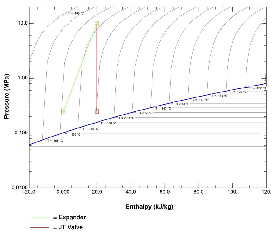
Table 1 shows the expansion process of pure methane prior to entering the storage tank in an LNG liquefaction plant with total process fl ow of 3 million tpy. The table compares expansion via the JT valve vs a cryogenic liquid expander. Liquid expanders can have 81 – 89% isentropic effi ciency.2 A production gain of 2% is calculated for the complete liquefaction process based on the lower temperature attained by the liquid cryogenic expander, which operates at 85% isentropic effi ciency. This equates to a total production gain of 60 000 tpy of additional methane for a 3 million tpy liquefaction plant. Figure 1 is the pressure vs enthalpy plot for pure methane. It shows the expansion process based on the inlet and outlet conditions listed in Table 1. Figure 1 shows the temperature and enthalpy reduction across the liquid expander.
In addition to the LNG production increase, cryogenic liquid expanders provide the benefi t of electrical power generation. Table 1 shows that for every 3 million tpy of pure


methane production capacity, 1.755 MW electrical power can be recovered.
In comparing liquefaction plants with and without liquid expanders, the main differences are as follows: In a new plant, for a given liquefied gas output production, the liquid expander allows for installation of less power generation, smaller gas compressors (propane, ethylene, methane, or mixed refrigerant depending on the liquefaction process), smaller gas expanders, and smaller heat exchangers. In an existing plant – or a new plant with given sizes of power generation, gas compressors, gas expanders, and heat exchangers – the liquid expander increases the liquefied gas output production.
Expander design concept
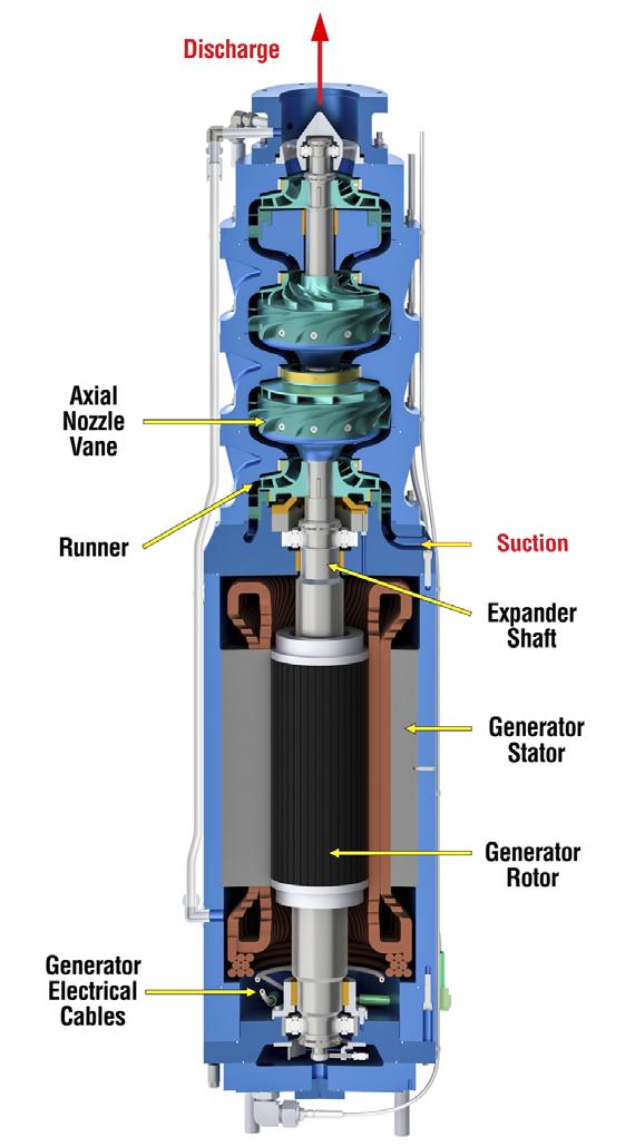
Figure 1. Pressure vs enthalpy (P-h) plot of pure methane, showing The high-pressure liquid stream at the end expansion via a JT valve and liquid expander for comparison purposes. of the traditional liquefaction process enters into the pressure vessel of the liquid expander, passes through each hydraulic component, and exits under low pressure through the top section, as shown in Figure 2. The hydraulic assembly consists of three stages, each with fi xed geometry nozzle vanes and a radial infl ow Francis-type reaction turbine runner. The nozzle vanes convert the fl uid’s static pressure energy into rotational kinetic energy, and the runner converts the resulting rotational energy into shaft torque. The electric generator and the hydraulic assembly are mounted on a common shaft. The generator converts the shaft torque into electrical power. The generator is submerged to the process fl uid to eliminate the need for a mechanical shaft seal and electric generator hazardous area certifi cations. Since there is no oxygen within the process fl uid, there is no possibility of igniting the highly explosive fl uid. Cryogenic power cables transmit the electrical power from the generator to the external power grid.
Conclusion
Cryogenic liquid expanders can improve a liquefaction plant’s process effi ciency and production rate. They allow for a 2 – 3% production gain and should be considered for all new and existing plants.3 Existing liquefaction plants that use older technology can also benefi t from an expander retrofi t as lower production costs will enable these plants to remain competitive with the newer installations currently operating or under construction. The production costs for liquefi ed gas are invariably lower with a liquid expander than without one.
Figure 2. Elliott typical three-stage upward flow cryogenic liquid expander.
References
1. VERKOEHLEN, J., ‘Initial Experience with LNG/MCR Expanders in
MLNG-Dua,’ Proceedings GASTECH 96, Volume 2, Vienna, Austria, (December 1996), ISBN 1874134162. 2. KARAKAS, E. ‘Turbine Specific Speed,’ LNG Industry, (December 2015). 3. KIKKAWA, Y. and KIMMEL, H. E., ‘Interaction between Liquefaction
Process and LNG Expanders,’ Proceedings 2001 AICHE Spring National
Meeting, Natural Gas Utilization Topical Conference, Houston, Texas, US, (April 2001).


