13 minute read
Driving Energy And Process Efficiency


Ormond O'Neill, Siemens AG, Germany, explores how using drives can maximise energy and process effi ciency in mining applications.


While most of the talk and focus in many process industries these days is on digitalisation and the positive aff ects it can have on eff iciency, cost reductions and the environment, it is very important to remember that the real workhorse and the backbone of most industries remains the industrial hardware. In mining, crushers, mills, hoists, conveyors, pumps, and more are needed to mine, mill, and transport the ore. In turn, these heavy mechanical devices need motors, drives, gear boxes, transformers, switchgear, and automation equipment to operate and perform their tasks.
The mills, including motors, gears and drives, are oft en the most important, expensive, and highest energy-consuming equipment in a mine, so it is important that the miner selects sustainable and energy-eff icient devices that are best suited to the grinding requirements.
Advantages of a drive
Modern milling, conveying, and hoisting applications rely on drives to operate and control their motors, in order to optimise the mining process and to minimise their carbon footprint.
There are four main mill types used for first and second stage grinding, namely semi-autogenous grinding (SAG) mills, autogenous grinding (AG) mills, high pressure grinding rolls (HPGR), and ball mills. The first stage of the grinding circuit traditionally uses SAG or AG mills, though in specific applications these can be replaced by HPGRs. The second stage involves ball mills. The AG mills, SAG mills, and HPGRs are usually variable speed applications, while ball mill applications, which were traditionally fixed speed, now tend to be variable speed as well.
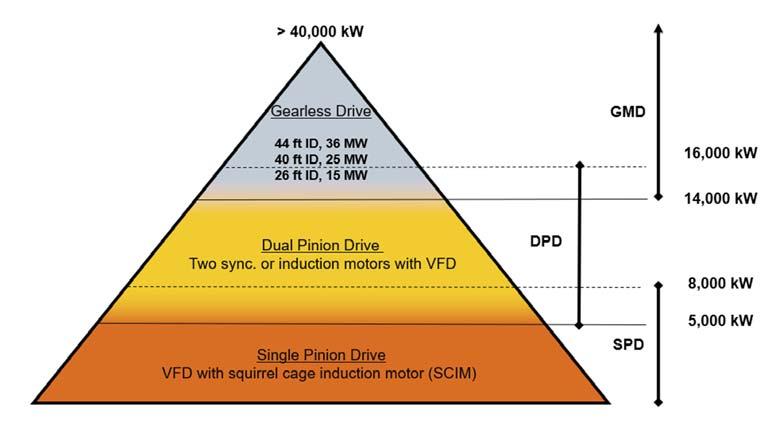
In the case of horizontal mills, the first step to determine which drive is best for the application is to define in which power and speed (torque) range the mill should operate. This determines whether a single-pinion, dual-pinion, or, for the highest power ranges, a so-called ‘gearless mill drive’ (GMD or ring-motor) system is best suited.
Due to wear and tear issues, the low power factor, the inability to optimise the grinding process, high transient torques during start up and high-inrush currents causing network instability, wound rotor induction motors (WRIM) with resistance starters (e.g. LRS) are becoming a thing of the past. The advantages of using a variable frequency drive (VFD) simply far outweigh the only real advantage of the WRIM/resistance starter solution, namely the relatively low capital cost of the equipment. The 24/7 operation of a mill means the CAPEX gains made can be wiped out in just one single day of additional maintenance downtime.
The use of a drive introduces variable speed control to applications, leads to a far more optimised process operation, ensures an ideal speed control, and minimises transient eff ects on weak networks.
In the case of horizontal mills, using a drive extends the lifetime of mill liners, ensures a smooth starting and stopping of the mill, reduces mechanical wear and tear of the gears, simplifies inching and creeping, and allows for the implementation of features such as automatic frozen charge detection (FCD).
Choosing the right drive depends on the application and whether high-speed (1000/1200 rpm) or low-speed motors (typically 180 rpm) are being used. This, in turn, oft en depends on the end-user’s trust in the availability and the reliability of the gearbox. High speed motors are driven using a drive and a gearbox between motor and pinion in either a single or dual-pinion configuration. Low-speed motors, on the other hand, use drives with pinions directly coupled to the motor, i.e. without gearboxes. Applications above approximately 18 MW are usually realised using GMDs. HPGR applications always use gearboxes in combination with drives and high-speed motors. The use of drives with load share control reduces roller wear and tear and optimises the grinding process.

Selecting the best motor
Figure 1. Power levels for the various mill drive solutions.
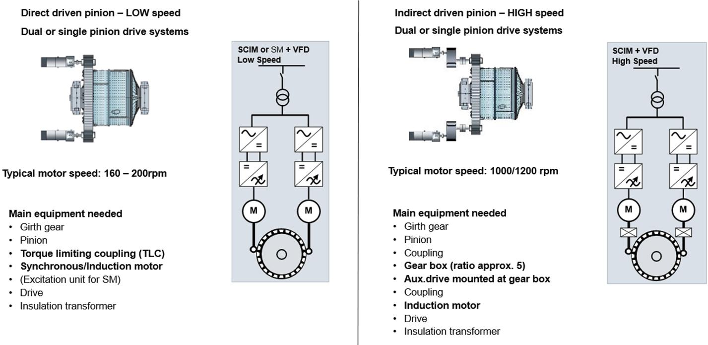
Direct driven pinion- LOW speed Dual or single pinion drive systems Indirect driven pinion- HIGH speed Dual or single pinion drive systems
Typical motor speed: 160-200rpm Typical motor speed: 1000-1200rpm
Main equipment needed · · · · · · · Girth gear Pinion Torque limiting coupling (TLC) Synchronous/Induction motor (Excitation unit for SM) Drive Insulation transformer Main equipment needed · Girth gear · Pinion · Coupling · Gear box (ratio approx. 5) · Aux. drive mounted at gear box · Coupling · Induction motor · Drive · Insulation transformer
SCIM or SM + VFD Low Speed
High speed solutions involve a gearbox in combination with an induction motor. These are cheaper from a CAPEX perspective and the individual parts are lighter/smaller than in low-speed configurations. However, the necessity of requiring a gearbox means they are generally SCIM + VFD less eff icient (up to High Speed 1.5% energy loss in the gearbox), involve more mechanical parts, are more prone to wear and tear, and require more maintenance. In addition, a small auxiliary drive to execute the maintenance modes of the mill is usually only required at the Figure 2. Standard mill configurations depend on the mill type and the required speed. main gearbox.

Low speed solutions involve drives (VFD), in combination with synchronous motors (SM) or squirrel cage induction motors (SCIMs), directly coupled to the pinion via a torque limiting coupling.
The use of low-speed synchronous motors is historically driven, due to the previous lack of existence of medium voltage (MV) drives and because the physical restriction of the induction motor construction, which means low-speed induction motors with 30 – 48 poles have a very low power factor of 0.6 or less to the mains. However, today the use of a MV drive in combination with a 6 – 12 pole induction motor means a power factor to the line of 0.95 can be reached. This, combined with the fact that modern drives can operate motors at any frequency – rated frequencies far below 50/60 Hz have become normal – means that a drive operating at a frequency range of approximately 15 – 24 Hz covers the typical speed range of 150 – 240 rpm used in horizontal grinding mills.
There are a number of advantages in using an induction motor instead of a synchronous motor, the most important being the simplicity of the rotor. An induction motor simply consists of a very robust squirrel cage rotor. No brushes, slip rings or excitation circuits involving transformers, rectifiers, or additional rotor windings are required. With the exception of regular lubrication of the bearings, modern SCIMs are maintenance-free and designed for at least 30 years of operation.
In addition to higher CAPEX, the other main disadvantage of low-speed motors is the need for a large auxiliary drive for inching and creeping purposes, if not executed by the main motor, as no gearbox exists. The need of a torque limiting coupling is recommended for such solutions.
What drive is best?
Having established the importance and advantages of using a drive, it is now necessary to select the right one. There are a variety of diff erent variable frequency drive technologies available, and while the power and speed rating of the motor are oft en the most important factor when choosing a drive, other issues – such as: voltage ratings, driving (two quadrant) or regenerative (four quadrant) capabilities, start-up torque requirements, variable or constant torque operation, the ambient conditions of the application, and the cooling method (air/water) – also play a deciding role.
Mill applications are constant-torque applications where the size of the motor and drive is mainly determined by the start-up requirements. The drives normally need to be designed for 150% overload at start-up.
Drives can be broken down into four main categories, namely 3(5)-level voltage source inverter (VSI) drives, multi-level VSI drives, cyclo-converter drives, and load commutating inverters (LCI). The VSI drives are based on IGBT and IGCT semi-conductors with DC capacitors, while cyclo-converters use pure thyristor-based technology. These three drive types are suitable for grinding applications.
The fourth drive type, LCI, with a reactor in the DC-bus, is not suitable for mill applications as it is physically not able to provide the high overload required to start up a mill. 3(5)-level VSIs are mainly 12 and 24 pulse drives. The IGBT variants come in both air and water-cooled designs, can operate both as two and four quadrant drives (in milling applications generally two quadrant drives are suff icient), operate in power ranges of up to approximately 6 MW per mill drive, and are generally cheaper than their IGCT counterparts. As with all the other drive variations, it is possible to obtain higher power levels by using parallel drive connections. The main disadvantage of the IGBT technology is the required derating at low frequencies and, of particular importance in mining applications, the high derating at very high altitudes.
The IGCT variant only comes as a water-cooled device, but has the advantage that it can operate in higher power ranges of up to approximately 8 MW per mill drive, and is also suitable for use in very low frequency applications. However, this drive also has a high derating at very high altitudes.
Multi-level VSIs, on the other hand, can operate as up to 36 pulse standard devices, resulting in very low harmonics to the mains, as well as to the motor windings. They come in both air and water-cooled designs, can operate both as two and four quadrant drives, and in power ranges of up to approximately 8 MW per mill drive in the air-cooled variant. A wide output voltage range between 3 – 11 kV is possible, and since both the voltage and current output is almost sinusoidal, very little heat is generated in the motor, meaning motors with standard insulation (DOL motors) can be used and no derating of the motor is required for drives operation. Similar to the 3(5)-level VSIs, the main disadvantages are the derating at low frequencies and the high derating at very high altitudes.
The resulting power factor to the mains of a VSI drive is usually in the range of 0.95/0.96.
The third category, the cyclo-converter, is an extremely simple and robust drive that comes in both air and water-cooled variants and, thanks to its thyristor technology, requires very little maintenance, while off ering an extremely high level of reliability. It can be used up to very high-power ratings, with approximately 9 MW with one mill drive for air-cooled operation. The main disadvantage of the cyclo-converter is its poor power factor of approximately 0.8, and the fact that it creates more harmonics in the power supply network. This means the cyclo-converter requires power factor correction and harmonic filters in the power supply network, which leads to additional expense and the requirement for additional outdoor space. This may not

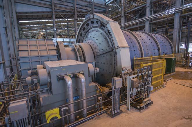
Figure 3. A copper milling application using two 6.5 MW low-speed induction motors with a cyclo-converter.
necessarily be a big disadvantage if the power factor compensation and harmonic filter for the cyclo-converter is considered when planning the power factor compensation and harmonic filter installation for the whole mine. Furthermore, the cyclo-converter itself is cheaper than the other drives and requires 50% or more less indoor space than other drives, so this compensates somewhat for the disadvantage and costs for harmonic filters. This, together with the fact that it is the most robust drive and best solution for high altitudes, due to its very low derating and its high eff iciency at both low-speed and low-frequency operation, means the cyclo-converter perfectly fulfils the requirements for low-speed mill drives in the mining industry.
Mill technology controller
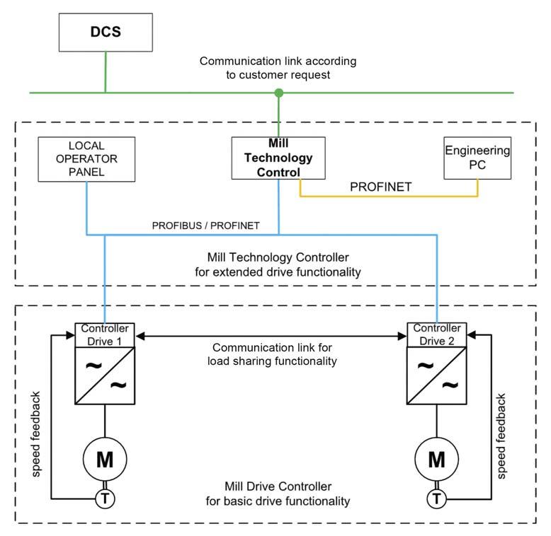
In pinion mill drive configurations it makes sense to install a mill technology controller (PLC) with the specific purpose of enhancing the functionality of the mills. One such feature is the frozen charge detection (FCD). By the PLC examining the start-up torque of the motor and automatically recognising the existence of a frozen or baked charge before it falls from the top of the mill, potential damage to the mill shell and the bearings can be avoided.
In the case of a dual-pinion configuration, the PLC eliminates unwanted counter-torque eff ects and ensures accurate load sharing between the motors, thus significantly reducing the mechanical stress on the equipment, prolonging the life of the assets, and increasing the mill’s availability and reliability.
Additional functions, such as mill stopping with balancing, creeping mode for maintenance and inching mode for positioning the mill in case of liner exchange, can also be integrated into the PLC.
Similarly, in HPGR applications the use of a technology PLC not only minimises the roller wear but, by controlling the load sharing of the motors, optimises the grinding throughput.
Digitalisation
Figure 4. Typical system configuration for Mill Drive Technology functionality. Each customer must decide for themselves where their priorities lie, but every modern drive system should benefit from the huge strides being made in digitalisation. Under the umbrella of asset health analytics (AHA), the correct use of sensors can provide detailed information to a cloud-based condition monitoring system, providing better system transparency, early fault detection, and reduced maintenance requirements and costs.
AHA draws data from sensors to monitor – among other things – the power supply; the drive; the motor and motor bearings; the gearbox; the pinion; the equipment mechanics, such as the bearings and the brakes system; the e-house; and the external water-cooling system. This data can be displayed in various dashboards for immediate visualisation and information, but also stored/archived over long periods of operation for further analysis. This long-term data archiving of the equipment (mill, conveyor, etc.) operational modes and measurement data is an eff ective means to document the equipment history. Furthermore, it allows the system to recognise long-term changes in an asset’s general condition during its operational lifetime, and uses this information to make specific recommendations for conducting maintenance tasks in time to avoid unexpected equipment failures or performance losses. This, in turn, leads to improved reliability and performance by contributing to a better overall understanding of the equipment’s operation, as well as facilitating the continuous development of solution design improvements as part of the product lifecycle. Such data analysis can be done on site by in-house experts or, via remote access to the site by motor, drives and gearbox experts, oft en in the form of service contracts. These service contracts generally involve regular reports of the status of the individual mine’s assets and allow potential anomalies to be recognised long before any damage can occur.
Make the right choice
Mining companies have their work cut out for them as they face declining ore grades, safety concerns, environmental protection regulations, decarbonisation, and volatile prices. Cutting-edge solutions for mills, conveyors, pumps, and hoists combining variable frequency drives with the right motor and digital technologies are the way forward, in order to ensure eff icient, eco-friendly solutions. The right hardware and soft ware combination will determine the future success of many mining applications. This is of particular importance for grinding applications, due to the size, costs, energy-consumption and importance of the mills, the key components in many mining processes.


