9 minute read
Flotation Control


Todd Loudin, Flowrox USA, outlines the benefi ts of rubber compounding pumps and valves in helping to combat abrasion.
There are many diff erent types of flotation in mining and minerals, including: column cells, which are tall round tanks that use compressed air to create air bubbles via spargers or cavitation tubes, and tank cells, which perform a slightly different flotation method and are often found on the outlet of the hydrocyclones.
In both cases, level control is performed by a control valve that maintains the proper level in the column to optimise the overflow of a froth of precious metals. In column flotation, the valve controls the discharge of waste and is generally a very abrasive environment. In both situations, the control valve performs a very vital function and must be capable to survive the environment for long periods of time before maintenance.
A control valve that requires frequent repairs is less than ideal. In some cases, the entire column or cell may need to be emptied for valve repair. In flotation cells, oft en a very simple control valve is utilised. This valve is a dart valve which is simply a plug that fits into the bottom of the flotation cell with a regulated opening to control the flow. This type of valve requires a box in which the valve is housed within. This metal enclosure adds significant cost to the cell overall pricing.
The correct valve for fl otation control
Most major flotation column manufacturers have recognised that pinch valves provide accurate control, but more importantly survive for long periods of time in abrasive environments. In flotation cell technologies, many manufacturers have eliminated the extra metal structure on the outside of the flotation cell to house dart valves and have begun to utilise pinch valves to control cell flow from cell to cell. When sizing the pinch control valve, special attention must be given to the head losses created by inlet and exit velocities and any losses through bends or elbows. Given the low driving head within a cell technology, these losses can result in improper valve sizing. A common mistake is to select a valve size that is too small for the intended flow rate. Some pinch valve companies have developed special


sizing soft ware that takes into account these piping losses and ensures the correct selection of the valve. Pinch valves inherently have very high Cv values, which allow for very high flow rates. Oft en, a single pinch valve can manage flow rates that would require two dart valves to perform the same flow rate.

Tailings management

For many years, pinch valves have been the desired valve for tailings control and isolation. In a tailings circuit, the solids may be extremely high: this could even be as much as 70 – 80% solids. Not many valves will survive in these high solids. Heavy duty slurry knife gate valves have also been utilised in these heavy slurries. Knife gate valves can (and do) survive in these environments, and have some benefits.
A slurry knife gate valve typically has a discharge cavity that allows solids or built-up material to be discharged out of the bottom of the valve on each closure. Knife gate valves off er the advantage over pinch valves of having a very short face-to-face and much lighter weight, especially in large diameters. Pinch valves have been utilised quite a lot in spigot valves for tailings distribution to the tailings dam.
The reason pinch valves are better than knife gates for longevity is that the rubber sleeve in the pinch valve has a straight through flow when in the open position – they are literally an extension of the pipeline. in addition, pinch valves have self-cleaning properties when scale builds up on the inner surface of the rubber sleeve: as the valve starts to close, the rubber is flexed. This starts to flake and break scale build up on the rubber sleeve. As the valve closes further, the fluid velocity increases and blasts away the remaining scale. Pinch valves have no pockets or cavities for material accumulation that is found in almost every other type of valve available. In high solids slurries, pinch valves are by far the most trouble-free valve available. That is providing the rubber sleeve is well engineered and manufactured out of high-quality rubber and is well compounded. However, it should be noted that, unfortunately, not all pinch valves are well made.

Thickener underfl ow pumping

Slurry centrifugal pumps are quite frequently utilised for thickener underflow pumping. These centrifugal pumps oft en have rubber linings throughout the pump and a rubber coated impeller to protect against the extreme abrasion. Over the past 10 – 15 years, peristaltic pumps have started to be the pump of choice for thickener underflow. The reasons the peristaltic pump has become more popular is due to both survivability improvements and the fact that this type of pump provides more accurate control of the thickener. Thickened slurry may include 60 – 70% solids before it is sent to filtration. When slurry percent solids increase, the mean time between failures (MTBF) of a centrifugal pump decreases sharply. A peristaltic pump can survive even 80% solids pumping. Peristaltic pumps are positive displacement devices. With each revolution of the peristaltic pump, a fixed volume of slurry is delivered into the piping. For this reason, the peristaltic pump can be very precisely controlled simply speed up or slowing down the rotation. Centrifugal pumps (when run at low speeds) typically come off their pump curves and become erratic and hard to control. One other reason peristaltic pumps are growing in this application is that they are relatively trouble free and very easy to repair. The most common failure is the rubber hose and it can be replaced fairly rapidly and at a much lower cost than repairing a centrifugal slurry pump.
Peristaltic pumps do have limitations. The largest limitation is their maximum flow rates. A 4 in. (100 mm) peristaltic pump will have a maximum flow rate of approximately 440 gal./min. Centrifugal pumps are made in much larger sizes than peristaltic pumps and can produce several thousands of gallons per minute. So, peristaltic pumps may be literally too small for very large thickeners in many mining operations. But the peristaltic, when and where it can be used for thickener underflow, is oft en a superior form of pumping, especially when solids percentages go above 50% solids.

Peristaltic pump differing operating principles
Peristaltic pumps were first manufactured in the 1930s. When rubber became more reliable, it paved the way for the peristaltic pump. There are three diff erent designs that have varying degrees of pump functionality and performance.
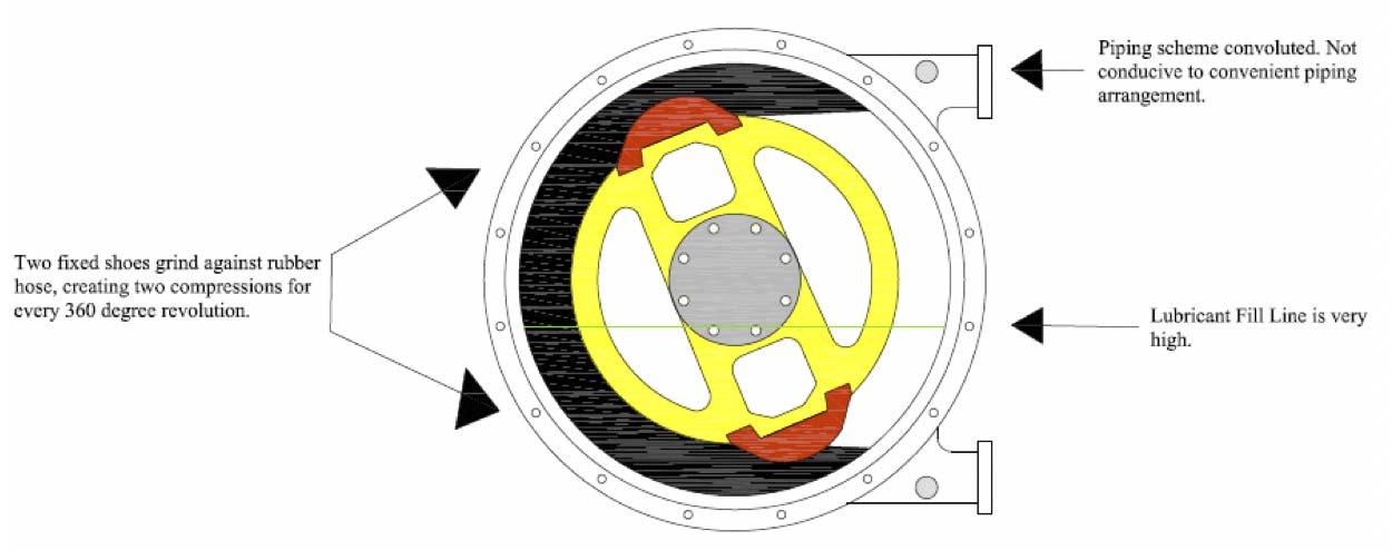
The first design, and probably the least desirable, is a shoe style peristaltic pump. This design typically has two fixed metal
Two fixed shoes grind against rubber hose, creating two compressions for every 360 degree revolution.


Figure 1. A shoe design peristaltic pumps generates significant heat and damage to the rubber hose. The pump also requires massive amounts of glycerin to dissipate the heat generated by the metal shoes rubbing against the rubber hose. Figure 2. Eccentric single rolling peristaltic pumps on thickener underflow at a Mexican mining operation.
Piping scheme convoluted. Not conducive to convenient piping arrangement. Lubricant Dill Line is very high. Cam shaft with roller that rolls over the hose. Lowest glycerin fill level.

In-line piping arrangement.
Figure 3. Eccentric single rolling designed peristaltic pumps compress the rubber hose only once per every 360˚ revolution, resulting in far superior hose life and lowest operating cost.
shoes that compress the rubber hose as the pump rotates in a 360˚ fashion. These metal shoes rub against the rubber hose and generate drag, friction, and heat. This style of pump needs to operate at very low revolutions per minute to prevent significant heat generation. If this style of pump is run at higher revolutions per minute, the pump assembly and rubber hose get very hot. These types of pumps have been implemented in mining operations where the mine uses a fire hose to keep the pumps doused to try to reduce the heat. In addition, this style of pump is filled approximately halfway with a casing full of glycerin to dissipate the heat that the pump generates. This large amount of glycerin adds significantly to the operating expense of the pumps. The second type of peristaltic pump is one that utilises two or more rollers to compress the rubber hose. The rolling design does not generate the heat found in shoe design peristaltic pumps. Generally, there are two factors that determine how long the rubber hoses last. The first is how many times the rubber hose is compressed; and the second major factor is the introduction of heat to the rubber hose. Since this design does not create immense heat like found in shoe designs, then the hose MTBF is better than shoe designs. Moreover, this type of pump requires either a very small amount of glycerin, or even none at all. The final design is an eccentric single roller design, which was first introduced to the market approximately 15 years ago. This design also does not generate heat from the rolling action. The biggest benefit of this design is that there is only one compression per revolution. The eccentric single roller design compresses half the number of times of both of the other two designs. Thus, this design will result in a hose life a minimum of two times longer than a multiple roller design, and a hose life two to five times longer than shoe designs. The savings in operating costs on an annual basis with this design can be as much as several hundreds of thousands of dollars if there are numerous peristaltic pumps utilised.
Conclusion
Mining is one of the harshest types of processing on the planet, where pumps and valves in this environment are subject to extremely abrasive mediums. There are two schools of thought on how to survive in abrasive flow streams. One is to make materials harder with special coatings such as satellite and others.
The other school of thought is to utilise soft elastic rubber to combat abrasion. In many cases, the rubber option will be the least costly, but still highly eff ective. Rubber compounding has advanced significantly over the past several decades: even in acidic mediums mixed with minerals, there are rubber compounds capable to handle both the acids and abrasion. Three diff erent rubber compounds ideal for such circumstances are EPDM, viton, and hydrogenated nitrile rubber.


