
10 minute read
Ready for anything


The most effective ways to respond to changes in feed gas flowrate and composition or process operating goals depend on where the process is running on the operational map and what constraints are either in effect or are close to becoming active. For example, absorbers are almost always either lean-end pinched, rich-end pinched, or mass transfer rate limited. The most appropriate response to an increase in raw gas flowrate, for example, depends on the regime in which the absorber is operating.
The most common challenges to operations are posed by changing feed gas composition and flowrate. These can occur at any time but they are especially prevalent around initial start-up when it is almost invariably learned that the design basis for the treating unit is not the reality that prevails at the time. Often units are designed with the ability to accommodate reasonable departures; however, sometimes such is not the case. Indeed, depending on the process configuration, a substantially lower gas flowrate occasionally cannot be treated at all. This will be the first example of intuition gone wrong.

Failure to treat when gas flow is too low


Figure 1 shows a CO2 unit that counterintuitively failed to treat to 50 ppmv CO2 when presented with only 10% of the design CO2 flow. This was a shock to everyone concerned. The cause was identified to be the low temperature of the rich solvent from the absorber. CO2 absorption is exothermic and it can cause quite a large temperature bulge to appear within the absorber. The heat of absorption is partially transferred to the gas which carries heat up the column. There, the gas meets cooler solvent and transfers some of its heat into the liquid phase. The solvent then carries the heat downwards where it meets a cooler incoming gas and transfers some of its heat back into the gas. This back-and-forth exchange often results in high temperatures within the absorber. But independent of a temperature bulge, the heat of absorption must eventually be carried out of the absorber in the treated gas and in the amine solvent.


Ralph H. Weiland, Optimized Gas Treating, Inc., USA, explores how to respond to changing process conditions in amine treating.


If the solvent flow is large and the gas flow is relatively low (as in the present case of a very significantly reduced gas flowrate) most of the heat is carried out with the solvent. The low gas flowrate translates directly into a low rich solvent temperature, caused by too little CO2 absorption (insufficient heat of absorption). This has consequences in the performance of downstream equipment.
The most immediate consequence was that the too-cold liquid feed to the LP flash unit functionally turned this piece of equipment into an absorber which recaptured some of the already stripped CO2. This pushed too much CO2 into the regenerator and prevented it from producing a sufficiently lean solvent to meet the 50 ppmv treating goal. Ultimately, the cause was the process configuration itself. It was too tightly integrated to permit it to adapt to the extremely low demand for CO2 removal placed on it. The natural reaction to inadequate treating is to increase the solvent flow, but in this example that would (and did) have the opposite effect – it made treating even worse. The correct response was completely counterintuitive and should have been to decrease the solvent flow and get the rich amine temperature up. To understand this almost certainly requires use of a high-fidelity, mass transfer rate-based simulator.
This is a case of what are quite reasonable expectations being thwarted by an unforeseen quirk in the process design. Specifically, very tight heat integration made plant operating highly dependent on heat of absorption. The situation became understood and the problem resolved through careful rate-based simulation. This case is discussed in greater detail by Fulk et al.1
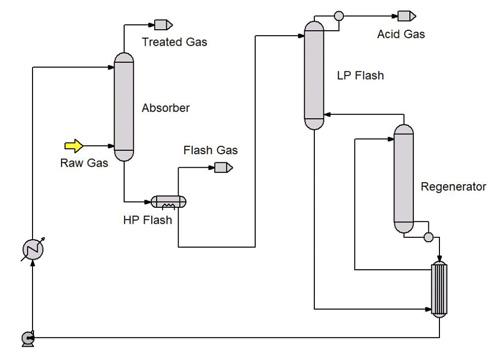
Figure 1. CO2 removal unit in an LNG plant.
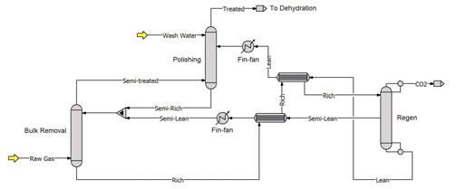
Figure 2. CO2 removal unit in a split flow plant. The schematic shows what would usually be a single absorber as separate bulk CO2 removal and polishing columns to make explanations more easily understood.
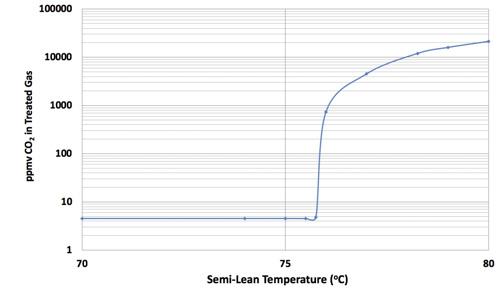
Figure 3. CO2 treating unit in a split flow plant.
Using higher solvent strength to process higher CO2 gas
A frequent circumstance on start-up is that the CO2 level in the feed gas is marginally higher or lower than the basis used in the original design. Low CO2 does not usually present a problem (the aforementioned case is an exception) but if the issue is higher CO2 in the raw feed gas, then tight pump designs may leave little room for increasing gas removal capacity. It may be possible to vary the loading of the lean solvent or to change the equilibrium backpressure of CO2 over the solvent by changing its temperature. However, adjustments in these parameters do little to change solvent capacity. The only parameter really available is amine concentration, and the natural inclination is to increase the amine strength to increase solvent capacity. However, a higher strength amine is more viscous than its dilute counterpart. One might suspect that this could adversely affect treating simply because higher viscosity means lower mass transfer rates, especially in a process where absorption is controlled by liquid-phase resistance to mass transfer such as CO2 absorption by a piperazine-promoted MDEA-based solvent. However, when amine strength is increased in response to higher feed gas CO2 concentration (all else remaining the same because of equipment constraints), temperatures in the absorber rise, the temperature bulge increases, and it turns out that solvent viscosity remains almost unchanged. In fact, the increased temperature raises the reaction rate of CO2 with the amine and treating may actually improve, although perhaps not as much as one might expect from reaction kinetics.
In an equipment-constrained system, using higher solvent strength in response to a higher-than-expected CO2 concentration in the feed gas is a very workable solution. However, one must be careful to keep rich amine loadings below the level dictated by the corrosion limits of the metallurgy of the tower, piping, and control valves. It also helps to be able to assess absorber internal temperature profiles to keep the bulge temperature below approximately 85˚C (185˚F) to prevent amine degradation and tower corrosion problems. This type of assessment is most readily undertaken using a mass transfer rate-based simulation tool such as ProTreat®.
Summer vs winter operations and quirks of split flow process configurations


Split flow process configurations offer some remarkable opportunities to make very bad decisions that can defy troubleshooting efforts for a long time. Figure 2 is a schematic of a split flow process layout. In such a process, achieving a very low CO2 concentration in the treated gas does not require all the solvent to be well stripped. In fact, most of the solvent needs to be only partially stripped. Partially-stripped solvent is used to complete bulk CO2 removal in the lower part of the absorber. Well-stripped solvent is fed to the upper part where it polishes the gas by removing the last vestiges of CO2 that were not eliminated in the bulk removal section. A considerable amount of regeneration energy can be saved by such a scheme, however, there can be pitfalls that reveal themselves in the hot summer months, especially in tightly-designed, heatintegrated plants.
Split flow layouts are less common in LNG applications than in syngas plants, for example, because the raw gas feeding an LNG train is usually fairly low in CO2 (typically 2%) so the energy saved by having lean and semi-lean amine solvent streams is outweighed by the additional equipment and greater complexity. However, if the raw gas is high enough in CO2 then the energy saved can more than compensate for the additional equipment.
The heat recovery provided by the rich-lean and richsemi-lean exchangers is fixed by their area and to an extent by their geometry (shell and tube vs plate and frame, number of passes, etc.). Final heat removal from the lean and semi-lean streams is provided by trim coolers, labelled fin-fan in Figure 2. The heat sink is usually ambient air, and it is here that one can get into trouble in a split-flow plant in a hot climate.
During summer months when daytime ambient temperatures exceeded 40 - 45˚C, this plant would fail precipitously to meet the 50 ppmv CO2 specification, not by a small margin but by thousands of ppm. One moment the unit was producing treated gas of much better quality than required, and the next the gas contained thousands of ppm of CO2, without warning of any kind. When this happened, of course, LNG production stopped. A modest LNG train produces 5 million tpy of LNG valued at roughly US$500 million – lost production represents approximately US$1.5 million of lost gross revenue per day (US$62 500/hr). The normal way to respond to loss of treat is to increase the solvent flowrate. Unfortunately, the lean amine pumps were already operating at absolute maximum flow so there was no room to manoeuvre. Inability to undertake any action to overcome the problem, combined with quite significant financial loss, made finding the root cause paramount. A great deal of effort was expended to identify the cause, but without success. In the end, the cause was revealed but only by careful mass transfer rate-based plant simulation.
Simulation led to identifying the semi-lean amine temperature as the culprit. Figure 3 shows how the simulated treating performance was predicted to respond to the semi-lean temperature. At approximately 76˚C the CO2 leak from the polishing column shows extreme sensitivity to semi-lean temperature. Below that temperature it is completely insensitive. Any CO2 that cannot be removed by the bulk column spills over directly into the polishing column which must remove it. As the semi-lean temperature rises, it can remove less and less CO2 and pushes ever more into the polisher. Eventually the polisher becomes overwhelmed. In the present case, this happens when the bulk column is removing 75% of the CO2 being fed to it. The polisher can remove 25% but nothing beyond that. The precipitous rise in treated gas CO2 level is simply the CO2 that the two columns are unable to remove.
It may be interesting to note that the process licensor appears to have been aware of this limitation because the licensor’s advice was to keep the semi-lean temperature below approximately 70˚C. However, the heat exchange equipment was too undersized to allow this recommendation to be heeded. Or perhaps at some time the plant capacity was increased without fully realising all the consequences.


Summary
In practice, intuitively correct responses to changing process conditions sometimes have the opposite effect to what was expected. Sometimes equipment constraints prevent the correct action from being taken. But whatever the situation, a predictive process simulator is often the fastest and most reliable tool to identifying the root cause of poor process performance and finding a solution. The cases discussed here were all resolved using the mass transfer rate-based ProTreat gas treating process simulator.
References
1. FULK, S., JONES, C., and WEILAND, R., ‘When real conditions diverge from design’, LNG Industry, April 2018.
VACUUM JACKED PIPE
Reduce Number of Expansion Loops R Re edu d ce ec Num mbe ber r of fo Exp pa ansi sion on Loo oo ps sp Longer Piping Runs with Fewer Joints Lon ng ger r Pip i in ni g g Ru uns s wit i h h Fe Few wer r Jo oJ in ni ts ts Increased Support Spacing In nI cr cre ease es d Supp po or rt Sp pa acin ng Lower Maintenance Costs Lo ow wer Maintenan nce C Costs
MOST COST EFFECTIVE WAY TO TRANSFER CRYOGENIC LIQUIDS WE OFFER TECHNICAL ASSISTANCE FOR YOUR PIPE SYSTEM DESIGN
ACME MODEL CV
• Versatile, Proven, Consistent • Bellows Sealed or Non-Bellows Designs • Exceptional Quality


