9 minute read
Mitigating moisture in cryogenic systems


Allen Dickey, Owens Corning, USA, explains how insulation can mitigate vapour drive and protect LNG facility function.

The cryogenic operating temperatures at which LNG systems function, along with the locations in which many LNG facilities are located, combine to form specific requirements for the insulation systems. When selecting insulation to safeguard a cryogenic system against vapour drive, several elements have to be considered: the permeability of the insulation, its ability to protect the thermal efficiency of the system, and its stability at extreme temperatures. These factors should influence the decision-making process. According to The Center for Energy Economics at the University of Texas, US, the first layer of protection for LNG facilities is implementation of the correct materials on-site and solid engineering design.1 Using a non-permeable insulation and proper accessories helps to defend cryogenic systems against the consequences of high vapour drive and promotes long-term thermal efficiency, stability, system lifespan, and facility safety.
Vapour drive in LNG facilities

It is estimated that 98% of insulation system failures are moisture related.2 Therefore, understanding vapour drive and protecting equipment from moisture damage remains an important element of designing insulation for use in LNG facilities. Much of the equipment on-site functions at approximately -161˚C (-258˚F). This temperature puts piping well below ambient conditions when in operation, although piping systems also can cycle from cold to ambient temperatures during shutdown periods.
Many LNG facilities are located in warm, humid climates nearing 32˚C (90˚F) with humidity levels close to 90%, which increases the potential for water vapour transmission (WVT) into the insulation system. Warmer air has a higher capacity for vapour pressure, or the stage when water exists in equilibrium as liquid and vapour. When that equilibrium changes or meets a colder surface, water condenses until a new balance is reached. The differential between ambient and LNG system operating temperatures increases the vapour pressure, driving moisture toward the colder object, and heightens the risk for moisture to penetrate permeable or incorrectly installed or damaged insulation systems. Once moisture starts to collect in LNG system insulation, there is a risk of it freezing, which will increase damage to the insulation and further reduce its effectiveness. Once started, damage to insulation can continue as moisture travels closer to the surface of the pipe. It is possible for moisture intrusion to create a freeze thaw movement pattern as pipe temperature cycles during use and shutdown periods.
A comparison trial examined the level of vapour permeability in several different types of insulation, including cellular glass, flexible elastomeric foam, polyisocyanurate, and nano/micro porous or fibrous insulations.3

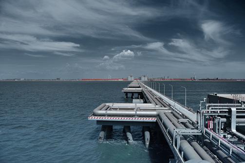
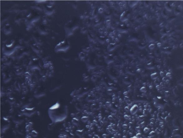
Figure 1. Often located in warm, humid regions while running piping and equipment at low temperatures, LNG facilities face the potential for damage from moisture penetration into insulation.
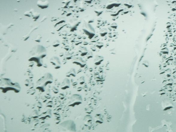
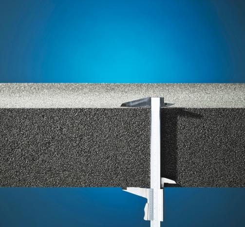
Figure 2. A lack of stability in insulation materials when exposed to cold temperatures – such as those generated by LNG pipes – may leave gaps for moisture, allowing for ice build-up and system damage.
Of those examined, only cellular glass insulation was completely impermeable. The material is also nonabsorbent according to ASTM C240.4 Additionally, cellular glass insulation has a water vapour permeability of 0.00 ng/Pa·s·m (0.00 perm·in.) when tested according to the ASTM E96 Procedure B (wet cup) method and does not increase in weight when exposed to 90% humidity.4 Weight gain in insulation resulting from moisture accumulation caused by surrounding humidity can overload pipe supports and cause damage to piping and equipment, reducing the lifespan of the system.
Reducing the risk of stress corrosion cracking with insulation and accessories
Metal pipes can be at risk of corrosion under insulation (CUI) when moisture penetrates insulation. LNG facilities typically use stainless steel piping. However, these pipes have the potential to develop stress corrosion cracking (SCC) when water infiltrates the insulation and certain chemical conditions are met. According to the U.S. Department of Transportation, SCC occurs when stressed pipes, or pipes under pressure, are in contact with water and specific chemical elements – often chlorides.5 Even when not in use, LNG pipes are stressed because of their production process, and when also exposed to moisture and non-neutral chemical conditions, they are at risk of cracking. Temperature cycling periods may increase this danger.
One way to improve system resilience is to carefully select insulation accessories, such as jacketing, mastics, and vapour barriers. With permeable insulation, any damage to these materials leaves the insulated system vulnerable to moisture penetration. Poorly installed and/or improperly selected accessory products place system performance and lifespan at risk. The establishment of an effective vapour retarder for the insulated cryogenic system is jeopardised by the use of inappropriate materials or poor installation. When a vapour barrier jacketing is installed with correctly applied impermeable insulation, such as close-cell cellular glass insulation, and insulation joints are sealed, it helps protect the system from freeze thaw damage and supports joint integrity. Combining impermeable insulation with wellselected accessories also helps compartmentalise the insulated system, which further reduces the risk of catastrophic failure by isolating insulated sections and preventing the migration of moisture if a particular location is compromised.
It has been estimated that the use of properly designed insulation systems to reduce heat transfer in US industry facilities lowers energy consumption by approximately 200 million bpy of oil.6 In an LNG system, insulation can be used to help maintain pipes at a pre-set temperature by minimising heat flux, which supports lower operating costs.
The intrusion of moisture into insulation surrounding LNG pipes reduces thermal efficiency and increases energy consumption. Industry studies have noted that open-cell insulating materials see up to a 23% increase in thermal conductivity following a 1% increase in moisture.7 Although low-permeability insulation is often used in a system composed of multiple layers of both insulation and vapour barrier jacketings, the installation of an impermeable insulation eliminates the need for more than one vapour retarder, reducing field labour and install costs.
Another element to consider when selecting and designing insulation for LNG pipes to prevent premature system failure is the substance’s co-efficient of thermal expansion (CTE). Thermal insulation and steel piping will expand or contract at different rates with changing temperatures. When an LNG system is cooling to temperature, the insulation and pipe will contract by different amounts. In one study, both polyisocyanurate and cellular glass insulations were lowered from ambient to -170˚C (-274˚F). The amount both materials contracted was compared to contraction rates for both carbon and stainless steel experiencing the same temperature drop. Throughout that temperature change, cellular glass insulation tightened


Made in Germany
T +49 2961 7405-0 info@rembe.de
Your Specialist for PRESSURE RELIEF SOLUTIONS

Consulting. Engineering. Products. Service.
somewhat less than carbon or 316 stainless steel, while the polyisocyanurate insulation contracted more than the steel.3 Contraction of the insulation could potentially create gaps for vapour to penetrate and ice to form. However, cellular glass insulation has been found to have excellent dimensional stability and to more closely match the substrate when compared with other insulation materials. Cellular glass insulation also has high compressive strength relative to its density – verified with testing according to ASTM C165/ C240/C552.4
Supporting and improving facility safety
Another consideration for insulation selection and system design for LNG pipes is to install insulation at a thickness that will provide a surface temperature on the outside of the insulation as close to the ambient temperature as practical while the system is in operation. Reaching ambient conditions in the external edge of insulation may prevent condensation from collecting on the insulated system. This design can play a role in addressing common safety concerns at LNG facilities, as an insulated system that does not absorb moisture or allow condensation to form reduces the potential for dripping to occur. Water falling from elevated insulated pipes can lead to wet pavement and slip hazards for those on-site.
Additionally, cryogenic piping is often supported on the exterior of the insulation system to eliminate potential thermal shorts that would lead to condensation and ice build-up in the location of the pipe support. Moisture condensing on LNG pipes can freeze and produce falling ice chunks, which further reduces facility safety. Using an impermeable or close-celled insulation can prevent moisture from condensing within insulation and dripping or forming ice.
Conclusion
The process of protecting cryogenic piping at an LNG facility from aggressive vapour drive starts with considering the types of materials and accessories being used in the insulation system. Selecting an impermeable insulation, such as cellular glass insulation, helps prevent the problems caused by moisture collecting on or penetrating into insulation by refusing to give water a pathway into the system. Reducing moisture-based risks helps the system avoid SCC and maintain thermal efficiency, supports safety, and limits the potential for damage.
References
1. FOSS, M.M., ‘LNG Safety and Security’, Houston, Texas: Center for Energy Economics, (2012). 2. ADAMS, L., ‘Thermal Conductivity of Wet Insulations’, ASHRAE
Journal, (1974), pp.61-62. 3. Owens Corning testing data. 4. Owens Corning, ‘Foamglas One Insulation data sheet’, (2020). 5. U.S. Department of Transportation: Pipeline Safety Stakeholder
Communications, ‘Fact Sheet: Stress Corrosion Cracking’, (2014), https://primis.phmsa.dot.gov 6. BHATIA, A. ‘Process Plant Insulation and Fuel Efficiency’,
Pipeline and Hazardous Materials Safety Administration, (2012), https://www.pdhonline.com 7. GUSYACHKIN, A.M. et al., ‘Effects of moisture content on thermal conductivity of thermal insulation materials’, IOP
Conf. Ser.: Mater. Sci. Eng. 570:012029, (2019).


