10 minute read
Steps to overfi ll prevention


Craig M. Carroll, Magnetrol Ametek, looks at the steps that have been taken to help prevent overfill spills, and how level instrumentation can help to reduce the risk of a catastrophic event.


In the early morning hours of December 2005, the largest fi re in Europe since World War II engulfed the Buncefi eld Oil Depot in Hemel Hempstead, England. Tank 912 located within the complex had overfl owed, which allowed the rapid formation of a vapour cloud; rich with a mixture of fuel and oxygen. Condensing and then fl owing outward from tank 912, the vaporous cloud spread in all directions. While the source of the ignition is not clear, something ignited the rich mix and the fi rst explosion rattled the oil storage terminal at 6:01 a.m. local time. Eventually, 20 large storage tanks ignited, which required a massive fi refi ghting effort. The fi re burned for fi ve days, destroying much of the depot before the blaze was fi nally extinguished. Thankfully, there were no fatalities from the explosion, but the scale, damage and potential for loss brought a focus to overfi ll prevention on a global scale. The investigation ultimately revealed the cause to be the failure of an overfi ll safety system (a combination of electro-mechanical servo gauges and a failure of the high-level switch for tank 912 in bund A combined to allow the overfi ll event). This safety system failed to operate and shut off the supply of petrol to the tank. The petrol would not easily explode in a liquid state, but when a large amount spilled out and mixed with oxygen, a concentration was reached which supported combustion. The transition of the petrol to a vapour state was rapid and exponentially increased the reach of the cloud.
Since that time and with a renewed focus on preventing occurrences such as Buncefi eld, guidelines, best practices and standards have been developed to provide operations with a clear direction for overfi ll prevention. The fi nal Buncefi eld report was released in 2008 and helped outline recommended practices for primary, secondary and tertiary containment of a potential overfi ll situation. These standards cover a wide range of overfi ll prevention areas.
Even with the best practices, in recent years overfi ll incidents have resulted in loss of life and billions of dollars in damages to petroleum facilities worldwide. Some of these incidents have been traced to the failure of the level control


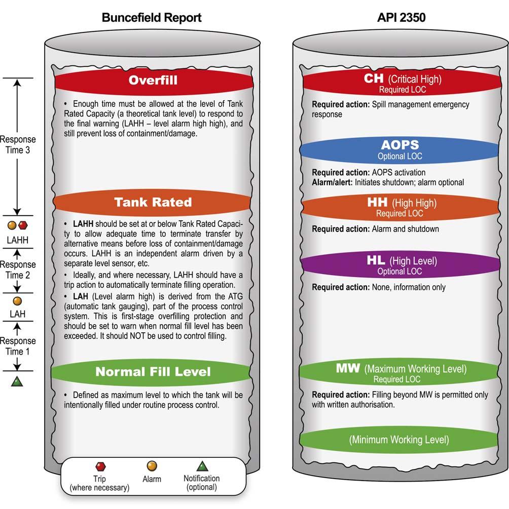
Figure 1. Action levels and response.
equipment which resulted in loss of containment of the fl ammable liquid. More common are minor spills that cause signifi cant environmental impact and result in millions of dollars in clean-up fees and environmental agency fi nes. There are multiple steps and activities that can be engaged to mitigate tank overfi ll issues.
In order to keep standards relevant, the American Petroleum Institute’s API 2350 5th edition guidelines for overfi ll protection of petroleum storage tanks have been revised. The latest edition combines the revised prescriptive standards with the functional safety standards of safety instrumented systems (SIS) as described in IEC 61511.
The following are guidelines standardised per API 2350 to mitigate the potential for overfi ll: Verify that all tanks have level control equipment and operational procedures. Review with senior leaders to embrace the principles of safety and environmental protection, as well as each being held accountable in mitigating risk. Employ a management system including a formal approach to: training, risk assessment, scheduled inspections, periodic testing, and equipment maintenance programmes.
Vital to these new requirements is the application of level instrumentation as one part of a comprehensive overfi ll prevention process (OPP), which now addresses operational processes, including capabilities and response times as well as operating parameters for every tank; including equipment category, level of concern (LOCs), response times and alarm procedures. Magnetrol Ametek has provided instrumentation that has met or exceeded the API guidelines for decades, but complying is not simply about the equipment being used to avoid overfi lling vessels. Additional best practices have been included related to the environmental consequences of tank overfi lls which can also produce vapour clouds that may escape the secondary containment and reach an ignition source resulting in a vapour cloud explosion (VCE). Implementation of a risk assessment system is a key step in this process. While the API 2350 5th edition does provide an example of a risk assessment, it does not provide instruction on how to perform the risk assessment. It is also required that written procedures for operating under normal, abnormal, startup and shutdown conditions be performed. Lastly, communications between the supply facility and receiving facility should also be formally reviewed and available as written documents.
Risk management is a process put in place to reduce risk to an acceptable level by managing probability and consequence of potential hazardous events:
Risk = Probability X Consequence (likelihood) (severity)
If the risk is deemed unacceptable, it must be reduced by taking the necessary steps outlined as shortfalls: procedures, instrumentation, training or documentation. When evaluating the consequences, a qualitative or quantitative approach can be taken. The use of descriptors such as minor or severe injury can be based on experience or the potential outcomes to better estimate the consequences: Jet fuel fire. Flash fire. VCE. Boiling liquid expanding vapour explosion (BLEVE). Spills.

If the risk assessment covers multiple tanks, a risk screening activity may assist with prioritising and focusing resources on the highest risks fi rst. Screening can point out areas that are higher in priority and suggest which tanks or operating equipment merit fi rst consideration and resources. More than one risk assessment is recommended, as the review is considered subjective by the personnel who perform the assessment and each assessment is to be simply a tool to aid in making informed and educated decisions.
The oil and gas industry is no stranger to incidents that have resulted in stricter regulations and guidelines for operating safely and responsibly. Both the API and Health and Safety Executive (HSE) have guidelines to help ensure proper overfi ll prevention through management systems and safety integrated processes for level measurement in storage tanks. All of these guidelines are targeted at reducing the risk of a Buncefi eld-type incident occurring at any storage terminal; however, there are benefi ts to risk reduction that go beyond incident prevention, including a reduction in liability insurance for storage terminals. Storage terminal operators and insurance providers have different perspectives on liability insurance and how they evaluate and minimise the risk.
Assessing insurance risk
Insurance agencies look at how much a storage terminal location has minimised the risk of events deemed catastrophic to the environment and employees. Overfi ll prevention is one aspect of the risk mitigation that is reviewed for liability insurance. The insurance agency will review the local jurisdictional requirements and industry guidelines when determining the insurance rates. During this review, the insurance agent is looking for evidence that the safety measures are properly maintained, as well as having each safety measure functioning properly. It is important for the devices that are used as safety guards to have an ability to be easily tested and maintained. Many insurance agencies will make recommendations based on failure modes they have experienced to ensure safety. These recommendations include processes to maintain operation, but also features of the level transmitters or switches themselves. Level transmitters for tank level should have internal diagnostics that are able to identify issues when they exist. Level alarms (or switches)

Figure 2. Buncefield complex at the Hertfordshire Oil Storage Terminal.

should be able to be proof tested either electronically or manually to ensure proper functioning. By choosing the appropriate level transmitters and switches with these capabilities, along with additional safety measures outlined in API 2350, the overall risk of an incident is reduced and the insurance premium is much lower.
Assessing operation risk
From the insurance customer’s perspective, the narrative changes. Plant operations staff are concerned with the ability to operate effi ciently based on expenses and costs. Storage terminals have to manage both fi xed and variable costs in order to operate profi tably. As previously noted, this can be managed by making sure that risk has been reduced across the terminal. As facilities and their operators come into compliance with API 2350, they can justify to insurance agencies the effort towards reducing and mitigating risk. Typically, they can expect to be audited by the insurance entity (external or internal) to review their level instrumentation annually, so it is important to stay compliant. Operators take on a large amount of risk by not following the recommendations of the insurance agencies and could face fi nes for not complying with industry standards if an incident were to occur. They can evaluate the level instrumentation on the market, but it can help to seek guidance from suppliers for insurance agency recommendations.

Figure 3. External floating roof storage tank.

Figure 4. Fuel storage depot.

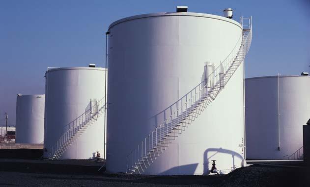
Figure 5. Vertical oil storage tanks with staircase.
Level transmitter and switch providers
By selecting the appropriate level instrumentation, a storage terminal site can demonstrate that it has taken measures to reduce the risk of overfi ll or other hazardous situations. As level instrumentation technology has advanced, continuous level transmitters have become more prevalent in storage terminal level control. There are many transmitters on the market that have self-diagnostics continually running health assessments of the device. Based on the storage terminal’s assessment of critical tank levels, the transmitter can identify when these levels are reached, allowing ample time to remove product from the tank as part of the overfi ll prevention system. Beyond previously using point level controls, continuous level measurement devices can provide real time level readings to control rooms while tanks are being fi lled/emptied. This helps the operator reduce the risk of having a dangerous event by knowing the tank level in real time. A further risk reduction step is to utilise additional point level controls as the fail-safe alarms. The continuous level device can have the output set to alarm certain functions, but if those were to fail, then the additional alarms at high and low level can provide emergency shutdown or emergency pumping of product to avoid an overfi ll. These devices can be as simple as a mechanical level switch with manual proof test capability, or they can be as sophisticated as an electronic point level switch using ultrasonic technology with built-in self-test diagnostics. Either of these are industry acceptable and provide an added layer of protection to meet industry standards and reduce overfi ll risk.
Overfill prevention resources
There are many level instrumentation products on the market that can help an owner/operator reduce the risk of an overfi ll spill or catastrophic event. They range from simple to complex, but all add to the goal of reducing the possibility of an incident. Magnetrol Ametek outlines information on industry standards with the offering of an overfi ll prevention kit. This kit outlines how to assess the important levels where instrumentation must control either a pump or a valve to ensure the product in the tank remains at a safe level. It then recommends the appropriate technologies based on tank alarm needs, the product that is in the tank and the type of tank confi guration. Using these level technologies demonstrates a reduction in risk. This can result in reduced insurance liability costs and improved profi t margins.


