8 minute read
Upping the standard


François Negroni, ALMA Group, outlines the benefits of using a standardised vapour recovery unit to handle emissions.


Avapour recovery unit (VRU) is an engineered industrial system dedicated to downstream petroleum storage and transfer activities. Before loading new hydrocarbons, trucks need to unload volatile organic compounds (VOCs) out of the tank. A VRU is the only clean solution to handle VOC emissions generated during day-to-day operations. Alternative options are to release directly into the atmosphere via a vent or to burn the system via a fl are advanced stack, both of which are not environmentally friendly.
However, VRUs are a highly-specialised fi eld that require specifi ed knowledge. Poor maintenance of a unit can lead to emission problems, safety complications, operational problems and fi nancial ineffi ciencies.
The capture and recovery of hydrocarbon vapours to reduce emissions of environmentally hazardous VOCs is a vital concern in modern oil and gas production and

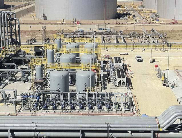
Figure 1. A customised VRU based on client-specifications (three aromatic units) in Saudi Arabia.
transformation. Increasingly more countries are adopting regulations to force oil and gas businesses to set up VRUs systematically for three main reasons: Environmental considerations, such as air pollution, VOC control, and impact on the health of humans and animals. Safety considerations, such as reducing the risk inherent to working in hazardous environments. Economic considerations, such as the loss of valuable products.
VRU process flow
The VRU process consists of three steps: Adsorption: hydrocarbons contained in the vapours are absorbed on activated carbon stored in large recovery units, once they are sent from the vehicle tank. Desorption: regeneration of carbon through the removal of hydrocarbons by means of vacuum. Absorption: hydrocarbons are re-absorbed in a liquid petroleum product (referred to as ‘absorbent product’) that is available on site. The absorbent is taken from one of the site storage tanks and then sent back together with the recovered product.
Vapour concentrations in hydrocarbons are infl uenced by the following: The type of products loaded (gasoline, diesel, etc.) and their chemical characteristics as Reid vapour pressure (RVP)/True vapour pressure (TVP). Site conditions, such as temperature and pressure. The type of loading operations (e.g. marine, railcar, truck, etc.). The recovery configuration at gas stations (top or bottom truck applications).
Concentrations may vary between 0 – 60 vol% (average mole weight is 65 g for standard gasolines). The aim is to fi nd the optimum ratio between the emission limit, recovery rate and energy consumption, without falling into an ecological issue (a lot of energy is consumed for a low recovery result, leading to a positive carbon footprint).
Emission limit requirements
Emission limit requirements (ELRs) include the following: 94/63/EC directive, the US Environmental Protection Agency’s (EPA) ‘Clean Air Act’, TA-Luft 01 in Germany, LRV in Switzerland (Air Pollution Control Ordinance [LVR00 App 2]) and NER in the Netherlands (the Netherlands Emission Guidelines for Air).
VRUs must be regulatory tested to demonstrate that the amount of hydrocarbons emitted into the atmosphere is below the limit. As such, VRU projects can be designed for classical ELRs such as 35 g hydrocarbon/m3 or 10 g hydrocarbon/m3, as well as more stringent conditions such as 150 mg hydrocarbon/m3, and even 50 mg hydrocarbon/m3 .
The goal of a standardised unit
The aim of a standardised unit is to propose reliable, simple, optimised systems for the treatment of hydrocarbon vapours in depots. This is based on the well-known pressure swing adsorption/absorption process, described previously. The new unit will respect industrial standards and norms such as: 97/23/EC – ‘EU Pressure Equipment Directive’ (PED). 2006/42/EC – ‘EU Machinery Directive’. 2014/35/EC – ‘EU Low Voltage Directive’. 94/9/EC – ‘EU Directive Explosion Protection
Guidelines’ (ATEX). 99/92/EC – ‘EU Directive for improving the safety and health protection of workers potentially at risk from explosive atmospheres’. 2004/108/EC – ‘EU Electromagnetic Compatibility
Directive’.
Standardised units include a programmable logic controller (PLC). To reinforce the PLC, VRUs from Carbovac (ALMA Group) respect a strict internal safety policy: Explosion shock proof design. General monitoring by a SIL3 Safety Relay. Vacuum systems based on dry screw vacuum pumps. Absorbent circulation pumps for supply and return, sealless with leakage. Double valves in absorbent lines to prevent leaks. Double monitoring on critical temperatures. Flame arrestor at the inlet of vapour line.
The vacuum system based on a dry screw vacuum pump has the best carbon footprint (compared to liquid ring technology) and minimum total cost of ownership (CAPEX + OPEX + waste cost) compared to rotary van technology.
Size design of different units
Generally, VRUs are designed according to the expected vapour profi le that they have to treat. This profi le depends on the terminal activity and the loading process, as stated before.
Unfortunately, the loading process is not the same from one country to another. Some countries are still using top-loading gantries, while others are using multi-product bottom loading gantries. The trucks are either mono-products or multi-products with several
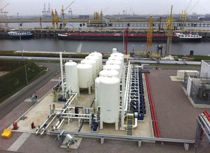
Figure 2. A 12 500 m3 XL unit in Western Europe, with maximum 150 mg hydrocarbon emission per m3 .
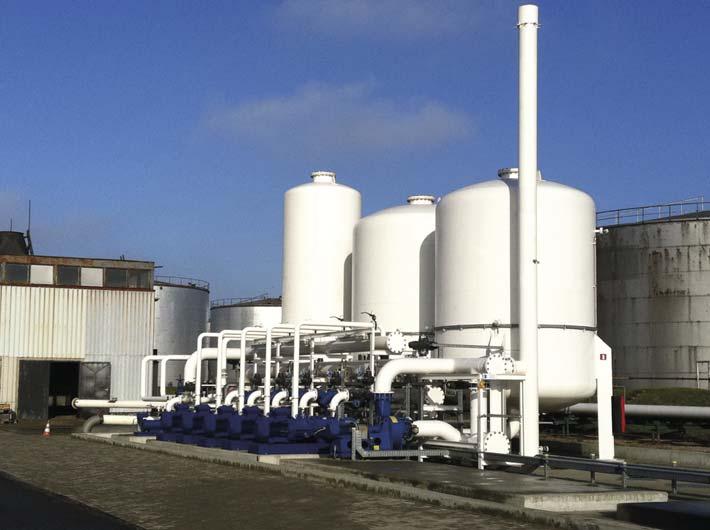
Figure 3. Standard VRU in Eastern Europe.
Automation
A VRU is fully automated, controlled through a PLC and monitored through supervisory control and data acquisition (SCADA) supervision. It starts and stops based on the loading process at the fi lling station, and uses a saving software to reduce the energy consumption and the running time of the unit.
In this respect, a typical feature of Carbovac technology is that its energy consumption is low, whilst maintaining a high operational fl exibility in respect of variable throughput, concentrations and range of products. For example, for typical gasoline vapours with 40% hydrocarbon concentration (1200 g hydrocarbon/m3), the energy consumption will be approximately 0.1 kWh/m3 of treated vapours.
The Carbovac PLC confi guration principle includes one main process PLC as well as a secondary watchdog PLC, which guarantees redundancy in all shut down functions. All rotating equipment is also frequency controlled to optimise the rotating speed and the life of the equipment and its energy consumption
compartments, and the requested emission is also different from one country to another.
All of these parameters have an infl uence on the quantity of the carbon and the size of the vacuum system that has to be designed for the units.
Based on these facts, the best compromise is to design four different sizes based on the quantity of loading gantries connected to the vapour treatment system. The following example illustrates the options with a dry screw vacuum pump:
Firstly, a small unit is used to handle the vapours from a multi-product loading gantry. The installed vacuum pump is a low vacuum fl ow capacity and the vapour line connection size is 4 in. In certain cases, depending on the loading process, this unit can be also suitable for two gantries.
Secondly, a medium unit is used to handle the vapours from two multi-product loading gantries. The installed vacuum pump is also a low vacuum fl ow capacity and the vapour line connection size is 6 in.
Thirdly, a large unit is used to handle the vapours from four multi-product loading gantries. The installed vacuum pump is a medium vacuum fl ow capacity and the vapour line connection size is 8 in.
Fnally, an XL unit is used to handle the vapours from eight multi-product loading gantries. The installed vacuum pump is a high vacuum fl ow capacity and the vapour line connection is 10 in.
Standardised units are suitable for medium and high concentrated hydrocarbon containing gaseous effl uents. The systems are initially designed for a level emission of 10 g/m3, but in most cases the units are able to reach very low concentrations of hydrocarbons and solvents by reducing the amount of inlet vapours or by switching to the next size of unit.
Installation and maintenance
By employing a standardised unit solution, on-site work is reduced. The mechanical installation and commissioning can be completed within two weeks by a reduced installation team.
For both environmental and economic reasons, it is essential that vapour recovery equipment is maintained at its optimum performance. Process equipment requires regular attention to ensure levels, temperatures and fl ow rates are within normal ranges and the plant is working correctly.
Spare parts should be available in stock and easily accessible to reduce shut down of the installation.
Conclusion
The intention of using a standardised unit is to fi nd the optimal solution with regards to cost effi ciency and environmental impact. The recovery of VOCs is a pressing issue for all parties concerned.
An operator’s impact on the environment is under scrutiny. By capturing VOCs effectively, operators are able to reduce their environmental impact and create a leaner process by reducing product losses.
For in-depth coverage of the global hydrocarbon processing sector
Page Number | Advertiser
IFC | American Tank & Vessel
37 | Aquajet Systems AB
09 | ATEC Steel
21 | Auma
IBC | Eddyfi Technologies
11 | ELAFLEX HIBY GmbH & Co. KG
29 | Flottweg SE
OBC | Gauging Systems Inc.
OFC & 33 | HMT
15 | John Zink Hamworthy Combustion
AD INDEX
04 | Midwest Steel
53 | NISTM
45 | Owens Corning
41, 50 & 56 | Palladian Publications
26 | Rembe® GmbH Safety + Control
02 | ROSEN
49 | StocExpo
19 | Tanco Engineering Inc.
25 | Trinity Consultants
55 | Turbomachinery & Pump Symposia