
11 minute read
Increasing availability


Marianne Williams, Emerson, USA, explains the significant benefits that can be achieved through the remote partial proof-testing of level measurement instruments in an overfill prevention system.


The overfi lling of process vessels and storage tanks containing hazardous materials has long been a leading cause of serious incidents in the refi ning, gas processing and petrochemical industry. The consequences of a product spill can be catastrophic, including injuries or fatalities to personnel, signifi cant damage to assets, harm to the surrounding environment, and damage to an organisation’s reputation.
The best way to deal with a potential incident is to prevent it from happening in the fi rst place, and best practice for minimising the risk of overfi lls involves employing several independent layers of protection. The critical fi rst line of defence is the basic process control system (BPCS) that monitors and controls the production processes. If the BPCS is functioning correctly, there is no need for the other layers of protection to become active.
An overfi ll prevention system (OPS) provides an independent second layer of protection. The OPS is normally dormant but operates when the BPCS fails to prevent the tank level from reaching the critical high point. The OPS stops the situation from escalating by alerting an operator, closing valves and/or shutting down pumps.
A thorough safety plan must also consider the worst-case scenario, where both the BPCS and the OPS fail to stop a spill from occurring. A third layer of protection is typically provided by a dyke or concrete wall

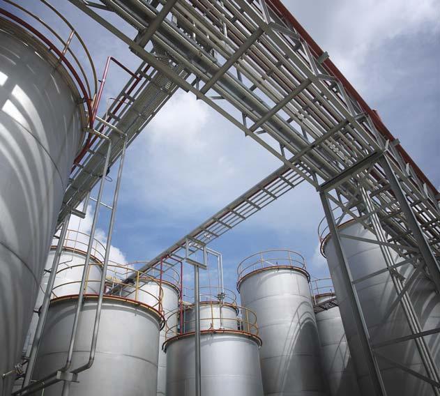
Figure 1. Traditional proof-testing methods require operators to enter hazardous locations or work at height to access devices, which poses a potential risk to their safety.
Figure 2. Remote partial proof-tests can be initiated by an operator issuing a command from the comfort of the control room.
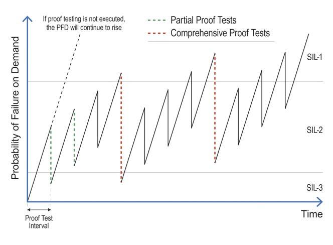
Figure 3. Partial proof-tests bring the PFD of the device back to a percentage of the original level and ensure it fulfils its specified SIL requirement. Partial testing can provide a technical justification for extending the time interval between comprehensive tests. that surrounds the tank to contain a spill. If required, the fourth and fi nal layer of protection is to alert the emergency services.

Safety standards
The OPS is the last line of defence for preventing a spill from happening and should be designed and implemented in compliance with the key global safety standards relating to overfi ll prevention. These are: The International Electrotechnical Commission’s IEC 61511 standard: this outlines best safety practices for implementing a modern OPS within the process industry and is an industry-specific adaptation of IEC 61508, which is an industry-independent standard for functional safety. The American Petroleum Institute’s API 2350 standard: this provides minimum requirements to comply with modern best practices in the specific application of non-pressurised aboveground large petroleum storage tanks, but can also be applied to certain tanks outside this specific scope.
Components of an OPS
An OPS can be either manual or automated. Manual OPS are easier to implement and less complex, with lower initial costs. They typically consist of a level sensor or switch that transmits an audio-visual alarm to an operator, notifying them to take appropriate actions such as manually opening or shutting off a valve to prevent an overfi ll. An automated OPS includes three basic elements for each of its safety instrumented functions (SIF): a sensor to monitor product level, a logic solver to poll the sensor and act when necessary, and a fi nal control element in the form of actuated valve technology to safely shut down the process. The reliability of the overall OPS is derived from the reliability of these individual components.
A formal methodology has been established to assess the reliability of each of the components and then calculate the overall reliability of the system. Probability of failure on demand (PFD) is used to indicate reliability. PFD is the likelihood that the component or system could fail at the very moment when it is needed. Reducing PFD therefore achieves greater risk reduction, and robust and reliable hardware reduces PFD and creates a more reliable OPS.
Proof-testing
Age increases the potential for hardware to fail. However, periodically checking the functionality of OPS components maintains confi dence in their ability to perform correctly when there is a safety demand, and verifi es that they are operating at the required safety integrity level (SIL). These checks are known as proof-tests and involve testing each component individually as well as each SIF as a whole, as a failure of any component would compromise the SIF’s ability to safely shut down a dangerous process.
The latest level measurement devices for OPS applications incorporate diagnostic software that detects
a failure and takes the device to a safe state. However, some failures are not detected by the device diagnostics. These are known as dangerous undetected failures (DUs) and are identifi ed during proof-testing. DUs are expressed as failures in time (FIT) and measured in DUs/109 hrs in operation. Ideally, the FIT rate should be extremely low, and selecting an instrument that provides a high level of diagnostic coverage will minimise FIT.
The effectiveness of a proof-test in fi nding DUs is known as the proof-test coverage factor, and this should be as high as possible. Ideally, the proof-test coverage would reach 100%. However, in reality, tests are not 100% effective. A high proof-test coverage does not always ensure a low PFD, but all things being equal, a device with a lower FIT will achieve a lower PFD.
Two types of proof-test – comprehensive and partial – may be performed in compliance with both IEC 61511 and API 2350.
Comprehensive tests
Comprehensive tests achieve the highest proof-test coverage and involve testing the entire SIF to ensure that all of its components are functioning correctly. This returns the PFD of the SIF very close to its original level. These tests are traditionally performed manually by technicians in the fi eld, with another worker in the control room verifying the reaction of the system.
To prove that a level sensor is functioning correctly, the product level can be raised manually to the activation point of the device under test. The danger of this approach is that if the device is a high-level sensor and fails to activate, this could lead to a spill. As a result, the latest version of API 2350 does not recommend that the tank level be raised above the maximum working level.
Performing proof-tests in this way consumes a signifi cant amount of time and manpower and can lead to the process being offl ine for an extended period, affecting process availability and having signifi cant cost and worker safety implications.
An alternative approach is to remove the instrument from the tank and perform a simulated test (known as an immersion test) in a different environment, such as a bucket. If the device is removed from a tank containing a hazardous or unpleasant product, the test would be performed in water instead. However, this would not prove that the device would work in the specifi c application, and the proof-test coverage would consequently be reduced. This method of testing also involves tanks being taken out of service for an extended period, thus affecting profi tability and exposing workers to safety risk. This method is also prone to human error when restoring equipment after testing.
Partial tests
Partial proof-tests have a reduced scope compared to comprehensive tests and are performed to ensure an individual device has no internal problems. Partial tests bring the PFD of that device back to a percentage of the
Need a reprint?


We can tailor to your requirements, produce 1 - 12 page formats, print colour or mono and more

original level and ensure that it fulfi ls its specifi ed SIL requirement. Whereas a comprehensive proof-test verifi es all three functional elements of a device – output circuitry, measurement electronics and sensing element – a partial test verifi es only one or two of them. However, a combination of partial tests that covers all three functional elements will reach a proof-test coverage close to that of a comprehensive test.
Partial tests do not replace comprehensive tests – they complement them. As a partial test detects only a percentage of potential failures, a comprehensive test must eventually be carried out after a given time interval to return a device to its original PFD. However, partial testing can crucially provide a technical justifi cation for extending the time interval between comprehensive tests, while remaining within regulatory requirements. This provides organisations with the freedom to schedule testing around planned shutdowns, resulting in signifi cant operational cost savings.
Remote partial proof-testing
The digital technology available in modern level instruments enables partial proof-testing to be performed remotely rather than through the traditional on-location approach. As a result, partial testing can be performed in minutes, thereby minimising process disruption, and can be performed in-process, without the need for raising and lowering the process material. Performing a partial test keeps workers out of harm’s way and results in signifi cant time and cost savings.
Consider the example of vibrating fork devices, which are typically applied within an OPS to provide high and low limit detection. In the latest advanced devices, remote partial proof-testing can be performed by issuing a HART® command from the control room. Upon receiving the command, the device enters test mode, whereby its fork frequency is simulated for on, off and alarm conditions. It then cycles through the different current output levels, verifying that there are no faults preventing the device from switching from the on state to the off state, or vice versa. The test exercises the processing and output electronics of the device, and since it is performed in-process, it can take less than one minute to complete the test cycle. On completion of the proof-test, a status is displayed within the control room to show whether it was successful. The device then automatically returns to operational mode, thereby eliminating the risk of it accidentally being left in test mode.
Remote partial proof-testing provides signifi cant benefi ts in terms of reduced time and complexity. As the instrument remains installed and does not need to be immersed during the test, tank downtime is minimised, and worker safety increased. Consequently, the ability to perform partial proof-testing remotely has become a key selection criterion when implementing point level technology as part of an OPS.
Real world savings
A major US refi ning and gas processing company is using this technology to help make signifi cant effi ciency and cost savings. The company operates a large number of compressor stations across several sites. Each compressor uses between two and four scrubber bottles, in which fl uid levels must be measured. The existing level measurement solution consisted of fl oat switches installed to provide a high-level alarm. The devices offered no real-time certainty of their functionality, were prone to wear, and required frequent rebuild. In addition, parts sometimes got lost in the scrubber bottle, causing additional issues.
The scrubber bottle works by knocking out any residual fl uid from the gas stream before it enters the compressor. High-level alarms are used to prevent liquid from entering the compressor and causing damage. A separate level switch is used to operate the dump valve to remove the fl uid build-up in the scrubber bottle. Proof-testing was a very important part of the process. If a high-level alarm failed, it would risk a spill.
The compressor stations are spread over a vast area, in remote locations and in areas where weather conditions can be challenging. Company policy required all the high-level alarms to be periodically checked and tested to verify functionality. This was a time-consuming, costly and potentially risky process. The scrubber bottle units were shut-in annually for inspection, testing and maintenance. Each fl oat had to be removed from the vessel for immersion testing, causing multiple safety concerns.
This process resulted in substantial lost time and production, as well as additional maintenance scheduling. Removing the fl oats tended to cause thread damage to both device and vessel over time. Including travel to and from the site and the draining of the tanks, the total testing time per fl oat switch could be several hours. The manpower required for testing meant costs added up to hundreds of dollars per unit tested.
To optimise its scrubber bottle maintenance procedures, the company replaced the fl oat switches with Emerson’s RosemountTM 2140:SIS vibrating fork level detectors. In total, 220 of these devices were installed across 110 compressor stations. The remote proof-testing capability of the device enabled functional high-level alarms to be confi rmed without having to travel to, or shut down, the scrubber bottle or compressor station. The remote proof-test is now performed in-process and completed in just a few minutes per device. The solution eliminated the company’s safety concerns because operators are not exposed to the process media during testing.
The devices were found to be very reliable, maintenance-free, and had the advantage of an adjustable switch delay which prevents false switching from turbulence. The company was able to reduce maintenance by approximately 1000 hours/yr and reduce its maintenance budget by US$264 000 through eliminating the need for annual manual testing of the fl oat switches. Avoiding shutdowns enabled the company to increase profi t by US$1 144 000, and the project’s payback period was approximately four months, with a return on investment of 28%.


