
10 minute read
The Natural Choice

choice choice

Reinhard Ringdorfer, Unitherm Cemcon GmbH, outlines the benefits for cement producers converting to complete or partial natural gas firing.


The production of cement is one of the most emissions-intensive industrial processes, with 600 to 700 kg of CO2 produced for every one ton of cement. Globally, cement production accounts for approximately 5% of man-made CO2 emissions. Most of the CO2 generated comes from the decarbonisation of limestone, which is the main raw material in cement production. Only a small percentage of the total CO2 is produced as a result of the fuels used. While secondary fuels are considered to be climate neutral, the CO2 from the primary or fossil fuels is subject to carbon tax. Therefore, it is in the best interest of cement producers to reduce the CO2 emissions resulting from the fuels used.
The amount of CO2 produced during cement production is directly related to the carbon content of the fuel, while the heat content is determined by both the oxygen and carbon content of the fuel. When fuel is burned, heat is released as carbon and hydrogen are combined with oxygen.


The main component of natural gas is methane (CH4), which has a higher energy content than other fuels and therefore a relatively lower CO2 to energy content. In an effi cient burner process, natural gas emits 50 to 60% less carbon dioxide compared to other fossil fuels.
Additional benefi ts of natural gas combustion include excellent control behaviour in terms of measurement and turn-down ratio, and the fact that there is no chemical impact on the process using these fuels, due to them containing few or no impurities. Due to the properties of natural gas, special care must be taken, and several standards have to be adhered to when designing the burner and auxiliary equipment such as valve trains, control systems etc.
Burner design
For the design of the rotary kiln burner, cement producers must distinguish between different applications: Natural gas fi ring in a single fuel burner. Natural gas fi ring in a combined burner. Natural gas fi ring for start-up or support operation in a low percentage.
M.A.S. Swirl Gas technology
The Unitherm M.A.S./SG burner is a deviation of the Mono Airduct System, designed especially for 100% natural gas fi ring in a rotary kiln.
The gas is split into the main gas (95 – 98%), which is fed through the fl exible hoses instead of primary air, and the central gas. The fl ame shape is adjusted directly with the fuel and not with the primary air, which is a unique feature. Low-pressure air is used for cooling purposes only. This design allows for maximum fl ame control with a minimum consumption of air.
The M.A.S./SG burner is also equipped with a ‘thermo-carbolysator’ (Figure 1), which is built into the burner’s central gas channel and is fuelled by approximately 2 – 5% of the total gas fl ow. A separate air supply is used to maintain the stoichiometric gas-to-air ratio. The thermo-carbolysator accelerates the process of the gaseous fuel heating until the gas is mixed with the secondary air. It provides continuous combustion without fl ame detachment during the heating up phase. Due to staged combustion, the burner improves the burning of bright materials such as white cement and lime.
In the fi rst combustion stage, the thermo-carbolysator mixes natural gas with low-pressure air inside the burner, ignites it, and forms a fl ame with the root located inside the burner. It provides an exceptionally stable satellite fl ame, due to the internal ignition of the gas.
In the second combustion stage, the main gas fl ow is heated by the satellite fl ame to over 1000˚C under the shortage of oxygen near the burner nozzles. In such conditions, the main fl ame starts to glow, thus the thermal radiation affecting the clinker intensifi es.
Combined rotary kiln burner
Natural gas can be fi red through one or two gas channels in a rotary kiln burner. The design will be determined by the main fuel used during burner operation.
Natural gas is usually injected into the burner at critical pressure, resulting in a velocity of more than 400 m/s. The momentum of the gas is usually two to three time higher than that of the primary air, which makes it complicated to adjust the fl ame with air. Due to this fact, it is very important that the gas fl ame can be adjusted by the fuel itself.
If natural gas is the dominant fuel used during cement production, the burner will be designed with two gas channels, one for axial gas, and the other for radial gas (Figure 2). When using two gas channels, the fl ame will be adjusted in the same way as with the primary air. More axial gas creates a longer, slimmer fl ame; if the radial component is higher, the fl ame becomes shorter and wider.
If natural gas is used only as back up fuel, the burner will be designed with one gas channel. The gas nozzle is designed with an opening at a certain angle to create a swirl. Additionally, the gas channel is
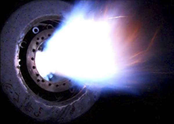
Figure 1. The M.A.S./SG burner is equipped with a ‘thermo-carbolysator’.
Figure 2. If natural gas is the dominant fuel used during cement production, the multi fuel burner will be designed with two gas channels, one for axial gas, and the other for radial gas.
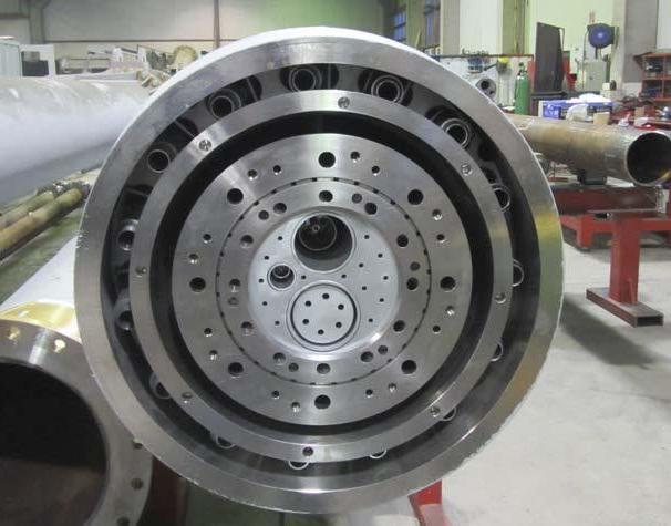
executed with an expansion joint at the cold end of the burner which allows for axial adjustment of the channel, including the nozzle. When pushed forward, a circular gap opens around the gas nozzle, introducing axial gas into the kiln and making the fl ame slimmer and wider.
Operation with gas lance
If natural gas is used only for heating up the kiln or as support fuel, a separate channel is often not necessary. The gas lance, or lances, can be either designed as separate units to be installed in a guiding tube (Figure 3) or as part of the central channel.
Usually, the lance, or lances, are designed for up to 50% of the total capacity. The nozzle is designed with a special geometry consisting of bores in different sizes and angles to ensure optimum combustion and a stable fl ame formation.
Gas valve train
The valve train must take care of all safety and control aspects, such as the safe start and stop of the gas operation, fl ow control, protection of downstream equipment from impurities and dirt, and supply of natural gas to the ignition burner.
The valve trains are designed as compact units to allow easy identifi cation of the parts and function on site. With the P&I diagram, the equipment list, the valve train drawing and the equipment numbering each part can be found easily.
The valve train entrance
Lock dirt and impurities out – different options are available depending on the application. A simple strainer is enough to protect the downstream equipment from a low volume of impurities in the natural gas. Other options include strainers or gas fi lters, or a combination of strainers and gas fi lters.
Pressure control
If necessary, the valve train can be equipped with a pressure regulator to keep the pressure constant and within the permitted limits for the downstream equipment. The maximum pressure is secured by a slam-shot valve triggered by high outlet pressure of the pressure regulator and is additionally secured by a safety-relief valve.
Start/stop
Safety shut off valves with intermediate ventilation guarantee the maximum safety and conformity with relevant standards. The valves are well tested and certifi ed from manufacturers well chosen from Unitherm’s long-term experience in combination with the feedback the company receives from its valued customers and service partners.


Flow control
The gas fl ow meter is a key component for continuous operation and fuel monitoring. A low to no maintenance requirement is combined with high accuracy and an excellent turn down ratio.
The better the turn down ratio, the better the ignition of the burner at the starting condition. As an additional benefi t, the burner may also be used for kiln drying operations with very low fi ring power.
Monitoring
Instrumentation is the key to constant and safe operation. Failsafe pressure monitoring needs to be applied to guarantee safety for operators and plant equipment.
Automation
The BMS (Burner Management System) is located mostly directly on the valve train and is equipped with an HMI display to allow operation and troubleshooting directly from the valve train location. Different communication protocols (Profi net, Modbus over Ethernet, Profi bus, etc.) or hardwired communication are available for communication with the plant PLC.
As the system handles the fuels for the burner, (most likely gases like natural gas or biogas, or fuels oils like light or heavy oil) it is very important that there are clear regulations for how the system must be designed to make sure the hazard is kept to a minimum. For industrial thermal processes, these minimum requirements can be found in the EN746-2.
According to the regulations (e.g., EN746-2) some relevant parts of the system (which also include the hardware/software of the BMS) have to meet a minimum SIL/PL and if a PLC is used, the PLC has to meet some extra regulations (EN ISO 13849 or EN 62061).
For a plant operator who is not so familiar with these regulations, and does not have the requirements on site (e.g., a safety PLC) it is easier to buy a ‘package’ – a valve train with a tailormade BMS. Many plants have very old valve trains (sometimes self-built) with the functions of the Burner Management System programmed in a non-safety (most of the time the DCS) controller. Plant managers should be aware of this safety risk.
Unitherm Cemcon’s Burner Management Systems are continuously developed further to meet the changing requirements of burners and of customers. The biggest benefi t of the BMS is that it can be easily integrated via any fi eldbus in the plant, as only the ‘START/STOP’ and fuel setpoint is needed to control the burner. All necessary other interlocks are already handled in the BMS and ensure a safe operation of the burner. For further diagnostics, all states, alarms, sensor readings, etc. are sent to the DCS to be visualised on the operator screen.
The BMS continuously monitors all necessary pressures and sensors, as well as the fl ame signal. In the event of an unsafe state, the safety shut off valves are immediately closed.

Figure 3. The gas lance, or lances, can either be designed as separate units to be installed in a guiding tube or as part of the central channel.
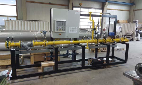
Figure 4. Gas valve train.
Figure 5. Unitherm BMS visualisation. Conclusion
If natural gas is available close to the plant, the conversion to complete or partial natural gas fi ring can be arranged rather quickly. Due to the easy handling of the fuel, a gas valve train with control system and a new or modifi ed burner are suffi cient for the fuel to be changed. Unitherm has installed numerous gas burners with supply systems around the world and works to improve the burner design with every new burner installed.


