
16 minute read
Material Progress In Sulfuric Acid Plant Design




MATERIAL PROGRESS IN


Nelson Clark, Joanes Barros, Matheus Sanchez, Bruno Ferraro, Gabriel Murakami, Lucas Camargo and Paulo Portilho, Clark Solutions, Brazil, investigate how special alloys have been changing the way industrial sulfuric acid plants are built and operated.
Since the first industrial sulfuric acid plants were built in the early 1900s, very little change occurred in the materials used to handle the harsh conditions of the acid-producing environment. More recently, the development and increased availability of special alloys has greatly simplified the design and construction of the plants – small, skid-mounted plants can now be built and shipped to customers for installation with minimal field work and assembly.
Oxidation converters
Sulfur dioxide (SO2) oxidation converters are the core of any sulfuric acid facility. As a general rule they are large, cylindrical, vertical vessels (though Clark Solutions has used horizontal vessels on small skid-mounted plants), housing three, four or five catalytic beds where the SO2 to sulfur trioxide (SO3) oxidation reaction takes place when the gases contact vanadium-based catalyst at reaction temperatures that range between 380˚C – 650˚C (715˚F – 1200˚F).

The high temperatures associated with the presence of a small amount of water and a SO3 rich atmosphere make the converter environment extremely aggressive. Historically, the approach to handling the gases in these converters has been the application of a refractory brick-lined carbon steel vessel shell coupled with high temperature resistant cast iron internals (support grids and posts).
Although construction can be excellent and long-lasting, carbon steel and cast iron have some disadvantages. The mechanical resistance of carbon steel is strongly affected in the temperature range above 500˚C (900˚F). Cast iron may experience deformation in temperatures above 650˚C (1200˚F).
The industry and designers always aim to increase production with the smallest plant possible. This drove designers to increase SO2 concentrations in the reactor and thus increase operating temperatures. First pass bottoms operating above 620˚C (1150˚F), unusual in the mid-1900s, became the new standard. Some plants, at the expense of fast catalyst ageing, would operate at 650˚C (1200˚F) continuously.
These accomplishments were only possible with the popularisation of different grades of stainless steels. The carbon steel and cast iron construction has slowly but steadily been replaced by special 304 stainless steel grades, more resistant to thermal stress and corrosion than carbon steel.
The new material has also led the industry to change converter design. While in the past the first catalytic pass had to be placed on top of the reactor due to thermal stress and increases in pressure drop, stainless steel construction (not as affected by thermal stress as carbon steel) allowed the first pass to be positioned wherever it made more sense to the designer. For simplicity, many designers chose to install the first catalytic bed at the bottom of the reactor. In addition, superheaters could be located on the ground level, which saved on ducting and supports.
The heavy duty high temperature resistant cast iron castings used for catalyst support and internals of the converter have also been replaced by special grades of 304 or 321 stainless steel, the last on the hotter areas.
With proper design, the new materials of construction allowed the refractory brick to be partially or completely eliminated, depending on process conditions, making the vessels cheaper and lighter than prior versions.
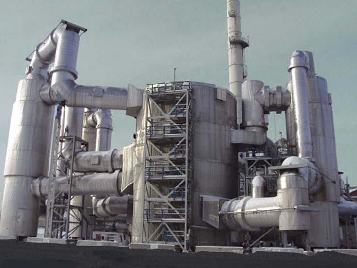
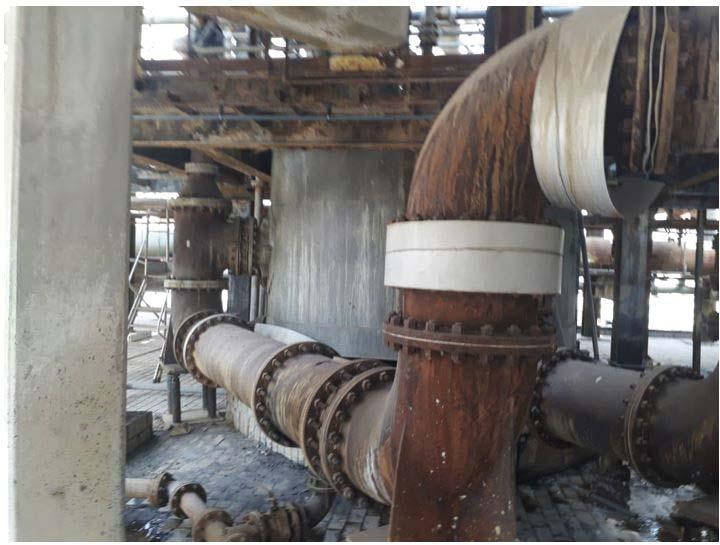
Figure 1. Sulfuric acid plant: the converter is the larger vessel in the middle of the image.
Figure 2. Corrosion on different alloys. Source: Handbook of Sulfuric Acid Manufacturing.1
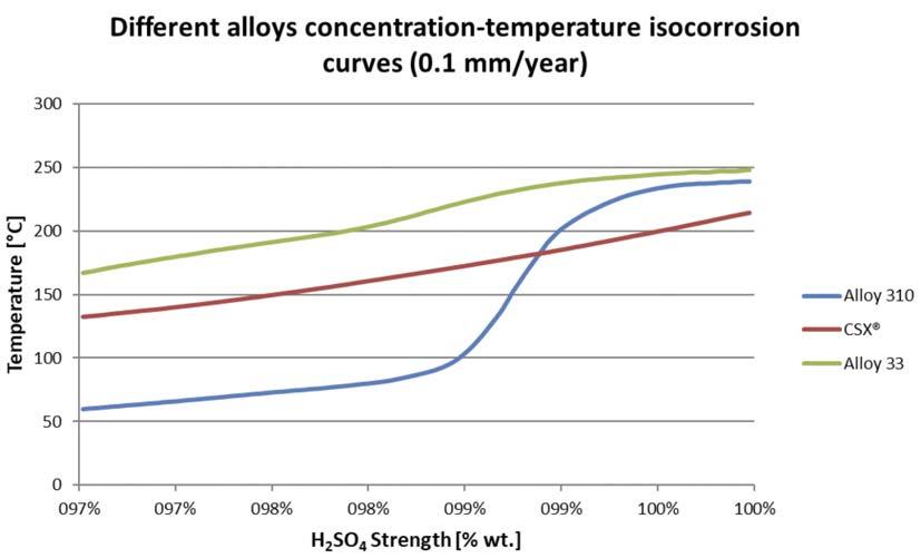
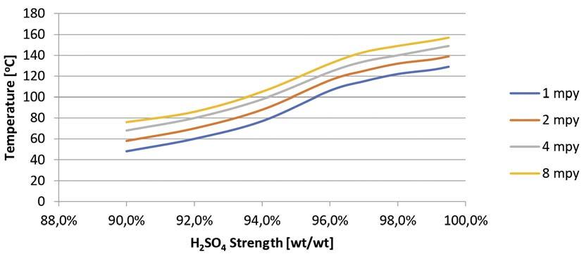
Figure 3. CSXTM Isocorrosion curve.
Gas-gas heat exchangers
Another traditional piece of equipment in double absorption plants that has benefitted from improved and more accessible materials is the gas-gas heat exchanger.
Heat exchangers cool the gases prior to entering the interpass absorption tower while at the same time re-heating the cold gases exiting the absorption tower. In the hot side of the exchanger high temperatures and SO2/SO3 laden gas are the challenges; on the cold side, acid mist and SO3 slippage are potential problems. In a way, the same problems afflicting the converter affect hot gas-gas heat exchangers.
Temperatures that could surpass 500˚C (900˚F) and the SO3 laden gas require that hot heat exchangers use resistant materials of construction. An early solution was metallised carbon steel, a strategy to make the base material bear the hot and harsh conditions.
The metallisation process is extremely diffi cult, though, and if done improperly can actually shorten tube life.
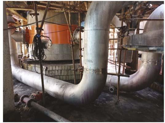
What happened with hot gas-gas heat exchangers has its parallel in cold gas-gas exchangers. For nearly a century gas-gas heat exchangers have been built in plain carbon steel. The material Figure 4. Cast iron line (left) replaced by a CSX line (right). In a small length, many flanges were selection is perfect and eliminated. should last a very long time with regular design operating conditions of the sulfate formation and pressure drop build-up, gas leaks, an exchanger. The only problem is that actual operation does increase in emissions, reduced capacity and earlier than not always go by the book. expected shutdown of the plant. This is why cold gas-gas
When engineers design a plant, they choose materials heat exchangers are among the items in most frequent that operate at the design conditions. The problem with need of maintenance and the most frequent cause of these designs is the non-expected operating conditions: shutdown in a double-absorption plant. low-capacity operation, poor air/gas drying performance, What is the answer to this problem? Gas-gas heat unexpected mist carryover from the interpass absorption, exchangers constructed out of stainless steel increase the improper SO3 absorption, and water or steam leakage. life of the equipment, reduce corrosion and sulfate
When one of these conditions exist, the cold formation in upset conditions and save money on both exchangers are pushed beyond their design limits. Hot, cleaning and maintenance. When properly designed and strong and corrosive acid will completely change the operated, stainless steel exchangers last longer and will dynamics of corrosion. When this happens, the pay for the extra cost incurred on a ‘total cost of consequences are the same: accelerated corrosion, ownership’ basis.
YOUR SPECIALIST FOR BAGGING & PALLETIZING


MOUTH & MOUTH& FFSbagging machines palletizing systems palletizing systems



Flexible and customized solutions
Industriestrasse 32, 8200 Gleisdorf, Austria Tel.: +43 3112 38580-0
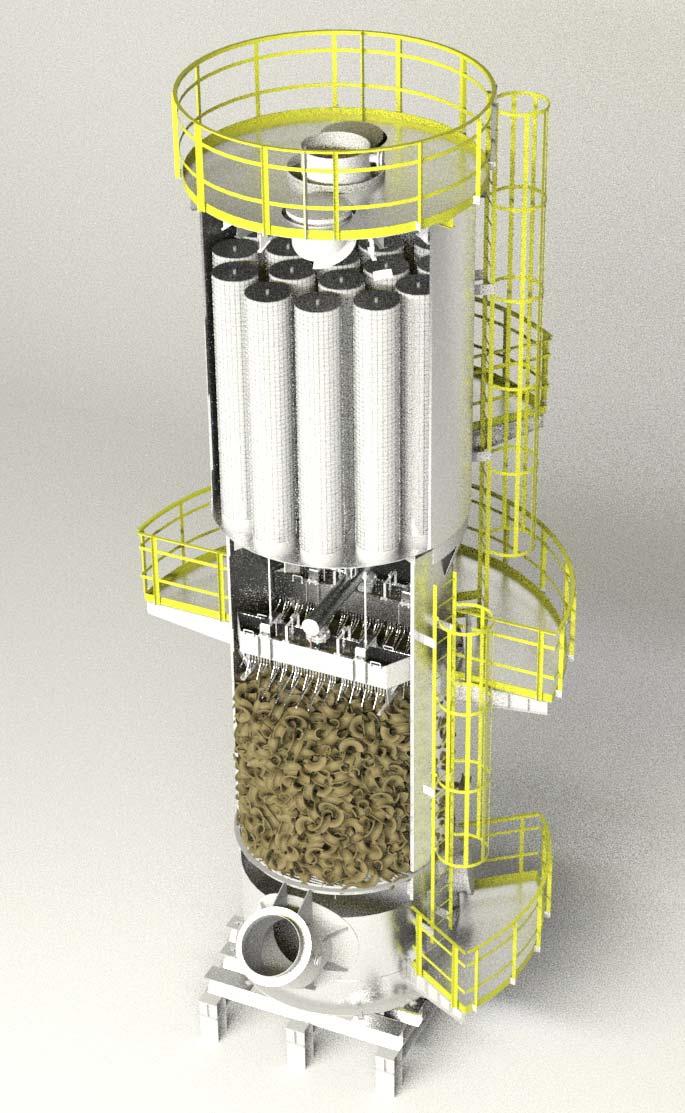
Figure 5. Complete 310MTM tower: not using brick increased the gas/liquid free flow cross-sectional area by 15%.
Strong acid piping
For more than a century hot strong sulfuric acid piping was designed and built using cast iron piping and connections. Cast iron grades changed from place to place, from country to country. Some places use 250# class piping and fittings to provide extra wall thickness for corrosion. Cast iron fittings and gravity cast parts have chaplets to separate the moulds, another weak point that in many situations is the starting point of a leak.
In the end, the corrosion resistance of cast iron allied to the thick walls has for a long time been the only option for strong acid piping, despite the natural shortfalls. Thus, the development of special alloys and steels, such as Clark Solutions’ CSXTM family of high silicon stainless steels, was very welcome.
Special alloys are designed to operate with corrosion rates below 0.02 – 0.04 mm/yr (1 – 2 mils/yr), while even the best cast irons will show corrosion rates in the range of 0.15 – 0.3 mm/yr (5 – 10 mils/yr) at average transport velocities. The thick walls guarantee a long lifetime, at the expense of substantial iron being captured by the acid.
As an example, while some of the most frequently used cast irons have wall thicknesses as high as 22 mm (0.9 in.), CSX piping uses wall thicknesses of 4 mm (0.2 in.) or 6 mm (0.3 in.) while still providing 20 or more years of service.
The thinner walls make special alloy piping lighter, but this is not the only advantage. Cast iron piping is generally operated with acid at velocities of 1 – 2 m/s. Corrosion rates on cast iron increase with transport velocity. CSX and special alloy piping are normally designed for approximately 3 m/s for long runs and 5 m/s for short runs. The special alloys’ corrosion rates are not sensitive to transport velocity, so the design is limited only by acceptable pressure drop.
Another advantage is welding capability. Welded lines substantially reduce the number of flanges used, which significantly reduces the risk of leaks at flanged connections. An even greater advantage is that in the event of a leak or failure special alloy lines can be locally welded: no cranes, no replacement of large parts, no new gasketing or tightening. This saves a substantial amount of time and energy when compared to cast iron lines, which may cost one or two days of production loss.
In Brazil, where Clark Solutions designed and replaced cast iron pipelines with CSX, the customer reported gains in plant operation and up to 60 – 80% less downtime compared to prior operation.
Drying and absorption towers and pump tanks
Drying and absorbing towers and tanks face the harshest conditions in an acid plant. As a result, it is this equipment that industry experts have the most disagreement about. The traditional approach to preventing corrosion is to build a brick-lined carbon steel vessel to avoid direct contact between the acid and the metal.
Every technology vendor has its special recipe. The basic concept underpinning the surface protection of this equipment is the installation of a resin or polymeric material, a rubber, an asphaltic mastic or a special resin in contact with the carbon steel shell, sometimes followed by an adhesive PTFE film over which potassium or sodium mortar is applied with acid-resistant brick.
Lining a carbon steel vessel so that it can operate with hot strong acid requires extremely skilled installers and considerable attention to detail. Properly built, a good lining system may last as long as 35 – 40 years. Skilled masons are becoming scarcer and more expensive though, and quality work takes time.
In addition, resins and polymers are not all the same – their resistance to acid varies. Shelf life sometimes affects performance. Improper mixing or installation may leave weak spots, where acid attack will initiate.
Bricks and mortars are permeable – it is a question of time as to when acid will contact the liners. If the installation was not properly built or if the materials were not properly chosen, the lining may last for just a few years.
Brick-lined towers and tanks are extremely heavy, requiring very strong foundations and in most cases requiring the lining service to be constructed in place.
New materials eliminate the need for lining, PTFE and brick. Towers and tanks, just like piping, can be in direct contact with the hot and strong acid.
Special alloys, such as the company’s CSX or Outotec’s SX, are the premium option for metal tower construction. Special grades of 310 stainless steel, such as the company’s 310M, can be used with good performance and long life in 98 – 98.5% strong acid and in heat recovery towers, where acid can be as hot as 240˚C and at concentrations as high as 99.5% in heat recovery systems, such as Clark Solutions’ Safehr®.
Lighter metal towers can quickly replace brick-lined towers, without requiring new foundations. In some replacement situations, eliminating the brick lining while keeping the outside diameter the same can increase the cross-sectional area, which can mean a substantial capacity gain.
Of course, nothing is perfect. Alloy towers do require proper concentration and temperature controls. While a short-term concentration or temperature excursion may be tolerated and will not lead to substantial corrosion, long-term excursions may accelerate corrosion and lead towers to an early failure.
Acid distributors
As in piping, improved alloys also took over acid distributor manufacturing. Cast iron distributors corrode, which means sulfate in the tower and iron in circulating acid. Sulfate on top of the packing may increase pressure drop and, in extreme cases, compromise drying or absorption efficiency.
Alloy distributors are currently built in different forms and designs, and are lighter in weight, simpler to install and less prone to corrosion. They also allow more design flexibility. Old standard irrigation densities used in cast iron distributor equipped towers are usually approximately 10 to 15 distribution points per square metre. This calls for increased packing heights to guarantee proper liquid distribution across the total height of the ceramic packing.
Special alloy distributors can be made of smaller parts that allow a much richer liquid distribution. Clark Solutions has built distributors for some special applications. For acid, given the nature of the service and the packing used, distribution densities with special alloy will usually vary from 25 to 50 points per square metre.
The 2 – 5 times denser irrigation creates a substantial reduction in packing heights, not only shortening tower heights but also reducing pressure drop across packing or allowing the design of smaller towers running at the same pressure drop.
Acid coolers
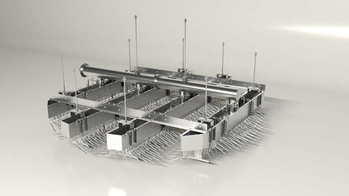
Figure 6. High-efficiency Clark Solutions trough and downcomer sulfuric acid distributor installed in a 6 m inner diameter tower in Brazil.
Figure 7. CSX shell and tube strong acid cooler. The first acid coolers used in the sulfuric acid industry were constructed from cast iron. Huge installations used very large areas where water would wet the external surface of the hot cast iron tube banks while hot acid was flowing inside. The water cooled the tubes by evaporation and convection, and the tubes cooled the acid flowing inside.
The long lengths added a substantial quantity of iron to the product acid. This additional iron can be a problem, depending on the industry. Cast iron coolers, such as piping, also used dozens and dozens of flanges and connection points, each a potential leak source.
The first attempt to replace the cast iron coolers started in the early 1980s with the introduction of anodically protected (AP) acid coolers. These shell and tube heat exchangers, with acid flowing on the shell and water in the tubes, operate with an impressed current.
One of the few disadvantages of the AP acid coolers is that the corrosion protection film formed by the passivation current film is temperature sensitive. An increase in the temperature may cause the metal to move from a passive state to an active state, accelerating corrosion. Luckily this is a rather unusual occurrence, especially when trained operators are in charge. The development of new alloys brought myriad options to the sulfuric acid producer. Shell and tube heat exchangers no longer need anodic protection; they can be built out of CSX, 310M, Alloy 3033 and others. Any of these are adequate for some process conditions.
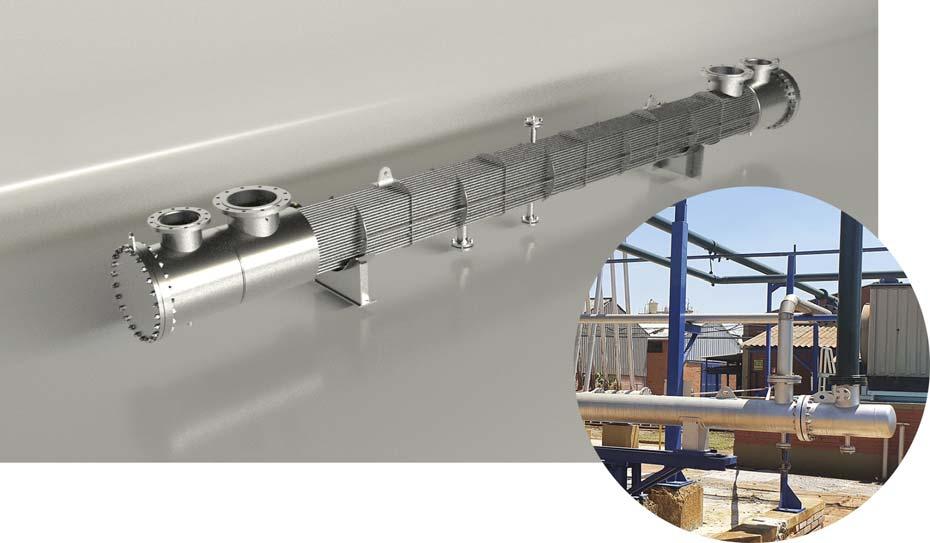
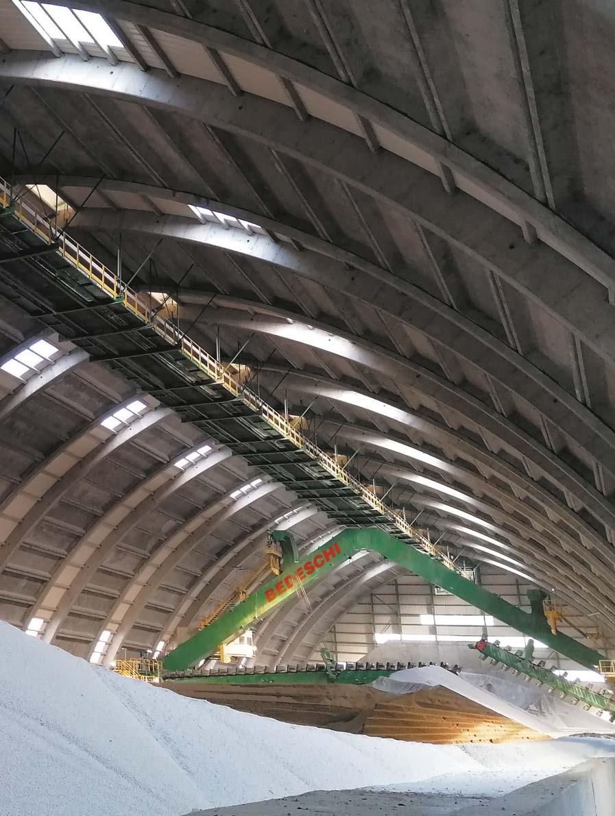

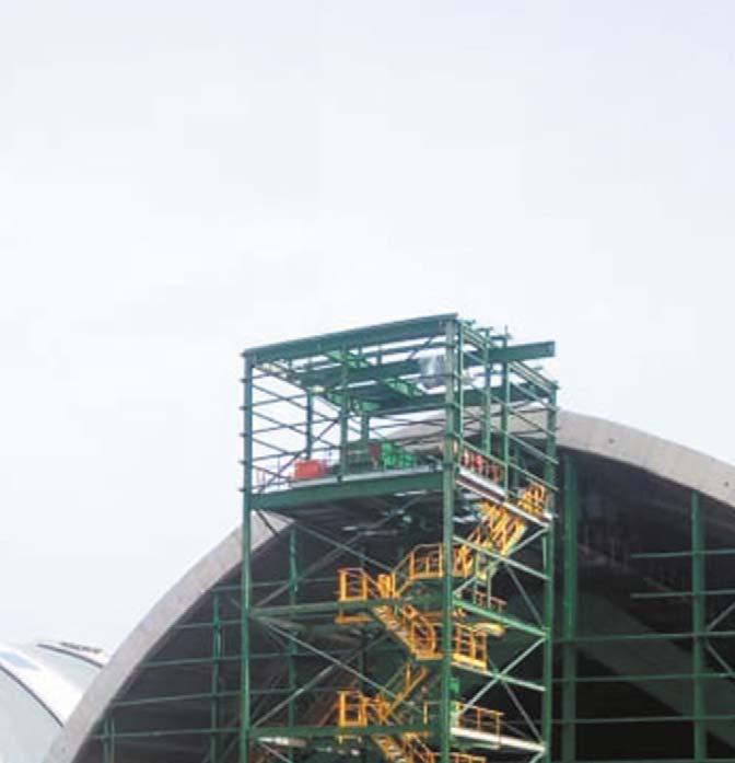
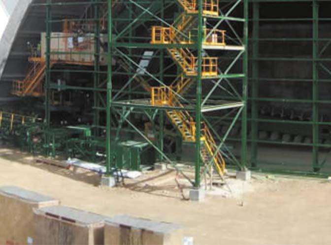


Figure 8. A shop manufactured modular acid plant requires minimal field work.
Alloyed shell and tube heat exchangers give the operator the same benefits of AP acid coolers with the advantage of not requiring the instrumentation and controls needed by AP acid coolers. Kept and operated properly, alloy shell and tube coolers will have a long service life with little maintenance.
The shell and tube were not the only heat exchangers to benefit from new alloys. Gasketed, semi-welded and fully welded plate and block exchangers can also be made of special alloys, such as Hastelloy D-205 or Alloy 33. Plate exchangers are smaller and cheaper than shell and tube exchangers.
However, a 0.3 mm distance between 0.5 mm thick plates requires good quality water treatment as well as an acid with little or no dissolved silica or other materials and ions that may foul, clog or precipitate corrosion on the plates.
Alloy plate coolers also work well at temperatures as high as 150 – 160˚C in 98 – 98.5% acid and without issues maintaining cooling water temperature or flow. Both are much more forgiving than AP coolers in this regard.
More recently, Clark Solutions and Alfa Laval developed a fully welded 310M block exchanger designed to handle high temperatures and concentrations of the Safehr heat recovery system. The newly designed 310M Compabloc® systems have now been in service at 99+% acid and 220 – 240˚C with no sign of corrosion and no loss of performance.
Conclusion
All the improvements provided by the development and application of new materials in the sulfuric acid industry combined to simplify, reduce the weight and increase the capacity of the new plants. These features allowed plants to be built faster, at lower costs and with less field labour.
As materials science progresses, even more improvements that will add to the simplification and reliability of new and future sulfuric acid plants are anticipated. Plants are getting lighter, more energy efficient and more reliable, and will continue to do so.
Reference
1. LOUIE, D.K., Handbook of Sulphuric Acid Manufacturing (2005).


