9 minute read
A successful start-up
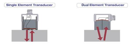
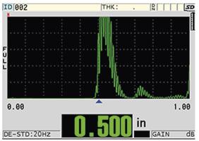
testing (NDT) is a sustainable option. NDT makes it possible to accurately assess a pipe’s condition for validation of expected rates of corrosion, and/ or to detect unexpected corrosion. Areas of concern can then be corrected before a breakdown or Figure 1. The visual schematic of a single element transducer (left) compared to a dual element catastrophic failure occurs. transducer (right). As a result of nondestructive inspection analysis, operators and organisations can determine the need for localised repair or more involved pipeline replacement. This promotes cost control while sustainably maintaining pipeline operations and high safety standards. How ultrasonic NDT helps inspectors monitor for corrosion Many times, an inspector only has access to the outside surface of a pipe, leaving them blind to the inside conditions. The use of ultrasonic technology can provide a nonintrusive monitoring of corrosion in pipelines. Ultrasonic NDT is used to accurately measure pipe wall thickness. Ultrasonic NDT using dual element transducers can help inspectors measure the remaining wall thickness of pipes to determine Figure 2. An example A-scan waveform display showing a thickness a pipe’s condition more accurately. measurement of 0.500 in. Theory of operation: how ultrasonic NDT technology works Single element ultrasonic NDT technology works by sending high-frequency sound waves into the pipe through a transducer. The transducer contains a piezoelectric element, which is excited by a short electrical pulse to generate a burst of ultrasonic waves. The sound waves travel through the pipe until they encounter a back wall or other boundary. They are then reflected back to the transducer, which converts the sound energy back into electrical energy. In thin-walled materials, such as those used to construct pipeline infrastructures, this energy can sometimes generate noise that can result in false indications and lead to unnecessary pipeline repair or replacement. Dual element transducers, commonly used in corrosion survey applications, differ from single element in that they have separate transmitting and receiving elements separated by a sound barrier. The dual element transducers also have Figure 3. The area in red illustrates the presence of corrosion and the thinning integrated delay lines with a slight roof angle effect that it has on pipe wall thickness. (Figure 1).


These design combinations optimise signalto-noise ratio by reducing electrical crosstalk or signals interfering with one another (caused by transmitting and receiving signals to and from a single element) while more effectively focusing the sound beam into the material, particularly advantageous in thin-walled material.
An ultrasonic flaw detector or thickness gauge can read these ultrasonic signals from the transducer and provide a visual waveform output on the device’s display, called an A-scan (Figure 2).
The visual display of the waveform on the device offers an inspector confidence in accurately assessing the thickness of a pipe as they can see what a digital reading corresponds to in real-time.
Working example To demonstrate evidence of corrosion using the ultrasonic NDT technique, we used dual element transducers in the pitch-catch (also called transmitreceive) mode. The dual element transducers contain two independently operated elements in a single housing. This means that one of the elements in the transducer acts as a transmitter (pitch) of sound energy and the other element in the transducer acts as a receiver (catch). Using the pitch-catch technique enables operators to detect areas of corrosion and accurately measure the remaining wall thickness from just one side of the pipe.
The dual element transducers used in this application have a frequency of 7.5 MHz and a nominal element size of 0.375 in. dia. Small dual element transducers such as these can be easily gripped with the fingertips, enabling them to be used in areas that are hard to access. They work well on pipes with a diameter of 1 in. and above.
The transducer is connected to an ultrasonic flaw detector. Here, we used an Olympus EPOCH™ 650 instrument. Combining the dual element transducer with the flaw detector enables users to accurately assess and identify corrosion zones, such as the area illustrated in Figure 3.
Using the DC1 (standard housing) or DC2 (thick-wall, wear-resistant housing) in a light scrubbing action, the inspector can identify areas consistent to nominal pipe thickness prior to degradation, as well as detect a corrosion zone and accurately measure correlative metal loss within that zone.
For this working example, and as shown in Figure 4, a DC1 transducer is used to measure the wall thickness of a metal pipe with a post corrosion nominal wall thickness of 0.325 in. The transducer and ultrasonic flaw detector work together to display a measurement of 0.322 in., indicating no real evidence of corrosion.
Comparatively, as shown in Figure 5, a DC1 transducer is used in a different zone location on the same metal pipe and displays a measurement of 0.251 in. The differential between the pipe’s post-corrosion nominal wall thickness of 0.325 in. to this lower measurement number indicates significant corrosion/material loss. Based on industry/inspection criteria, the operator can report the recommendation and disposition of the pipe for repair or replacement before a breakdown or failure occurs.
It is vital that every pipeline integrity management system includes corrosion inspection and monitoring to help ensure the continuous operation and safe transport of energy resources around the globe. As shown in the example, the accurate detection of pipeline corrosion can enable these areas to be repaired promptly before the corrosion leads to a more serious problem. This proactive pipeline maintenance approach helps protect the health and safety of people and the environment worldwide.

Figure 4. No evidence of corrosion: the ultrasonic flaw detector shows the nominal wall thickness of this pipe is 0.322 in. Figure 5. Evidence of corrosion: the ultrasonic flaw detector shows the minimal remaining wall thickness in this area is only 0.251 in.


Steve Jackson and Terri Mathis, Baker Hughes, Process & Pipeline Services, Houston, USA, detail a successful pre-commissioning project in the Gulf of Mexico.
The Sur de Texas natural gas pipeline was built between 2017 and 2019 by Infraestructura Marina del Golfo (IMG), a joint venture (JV) between TC Energy and Mexican infrastructure company IEnova. With the capacity to transport 2.6 billion ft3/d of clean-burning natural gas to businesses in central Mexico, this pipeline is an important development in Mexico’s plan to reduce its reliance on coal and fuel oil.
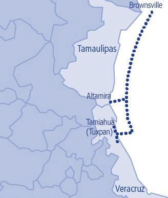
The 745 km (463 mile) line runs primarily under water in the Gulf of Mexico from just east of Brownsville, Texas, to Tuxpan. It has two segments. The north segment includes 500 km (311 miles) in the US that is owned and operated by Enbridge. This transitions to IMG ownership at the invisible subsea border from which it continues another 455 km (283 miles) to Altamira in Mexico, where it comes onshore. The south segment is all offshore, running 245 km (152 miles) from Altamira to Tamiahua near Tuxpan.
One of IMG’s challenges for the entire project was finding a contractor with the capabilities to handle pre-commissioning of this massive 42 in. subsea pipeline. Following a competitive bidding process, Baker Hughes was awarded the contract for the pre-commissioning work.
Solution The primary Baker Hughes project scope included progressive pigging during pipelay, filling, hydrostatic testing, dewatering, propelling inspection tools, drying and N2 purging. Baker Hughes also supplied the caliper tool for the north line. Baker Hughes had the proven experience, technical capability, a large and experienced talent pool, local resources and specialised equipment available in the region to reliably tackle the project.
Pumping The sheer volume of testing medium needed for hydrostatic testing at ~4000 psi required very large pumps that are not easy to find. High-power, high-pressure,

positive-displacement pumps, which Baker Hughes built specifically for this type of application, proved to be the right equipment for the job – with two very successful hydrostatic tests.
Filling One of the major technical challenges the project faced was pipeline stability. Since the line wouldn’t be buried until a later date, and it was in depths of just 10 - 40 m, filled only with air, there was concern that a tropical storm or hurricane could move or seriously damage the line and delay the project.
To solve this, Baker Hughes provided progressive filling of the complete offshore segments. The operation was originally planned to be executed with a filling spread from the beach; the amended construction schedule for the beach approach tunnels prevented this. The Baker Hughes technical solution to negate this was to contract an offshore jack-up rig equipped with a flooding spread. On the commencement of pipeline lay, Baker Hughes began the introduction of the test medium at the same rate as pipelay so it would be more stable on the sea floor. Great care was taken to keep the pigs and water far enough away from the lay vessel to avoid stressing the lay mechanism of the lay vessel. As the project developed, Baker Hughes worked from four different offshore vessels with full crews and large equipment spreads. Baker Hughes needed to show flexibility in adapting to the changing construction schedule, providing solutions, and keeping all teams well-briefed and extremely focused on safety throughout the entire operation.
Transporting equipment The southern-most connection site is separated from the mainland by a river and has no road access. Baker Hughes therefore utilised a cable-pull barge to transport equipment to the site at the edge of the beach. With the beach only about 2 ft above sea level, tropical storm season caused flooding difficulties and a small delay. All things considered, this part of the operation was not technically complex as far as pipeline pre-commissioning is concerned, but some creative problem-solving was required to address the scale and logistics challenges that had to be tightly managed to keep pre-commissioning on track.
Project safety Baker Hughes completed the project, having successfully filled, tested, dewatered, dried, and purged both the north

Figure 1. Sur de Tuxpan pipeline route.

Figure 2. Equipment spread staging in Brownsville, Texas.


