Rail Engineer - Issue 210 | September - October 2024
20| 24|
11|
12|
Calling for connectivity part 1: Labour’s report
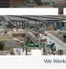
The Urban Transport Review examines how to accelerate connectivity within and between the UK’s key urban areas.
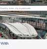
Calling for connectivity part 2: the mayor’s plan
The Opportunity through Connectivity report, published on 13 September, reinforces the conclusions of the Urban Transport Review.
A ‘Beacon’ at Garforth Garforth station’s new footbridge opened in July, replacing a 190-year-old North Eastern Railway cast iron structure.
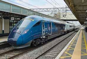
The curious case of the Class 805 improvement notice
Months after accepting the Class 805’s safety assessment report, the ORR now considers its operation breaches legislation. Why?
14|
The Semmering Base Tunnel: overcoming the Alps
The IMechE Engineers Eastern European Rail Tour made a stop at Austria’s Semmering Base Tunnel. Malcolm Dobell reports.
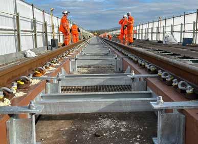
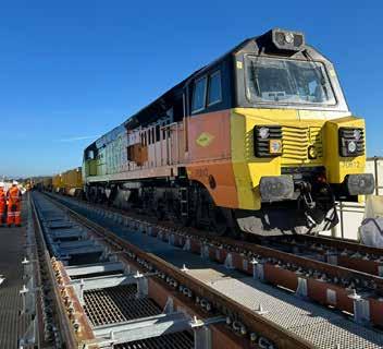
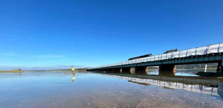
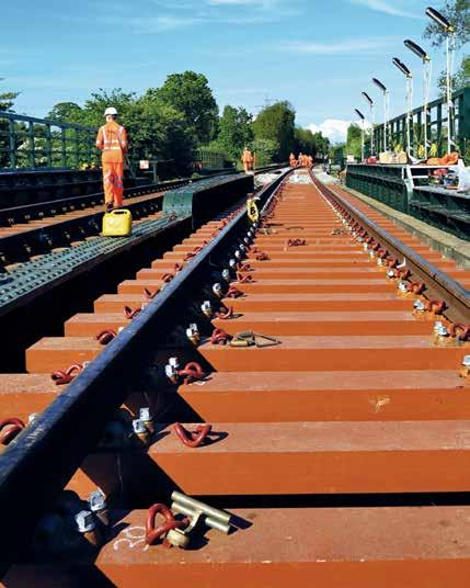
FFU: a sustainable choice for Eskmeals Viaduct
Sekisui’s FFU was incorporated into the design of this prestigious project, delivered between 6-23 September 2024.
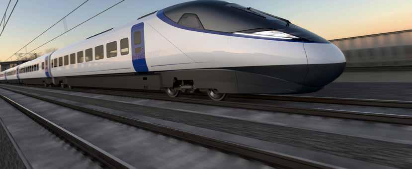
Testing on the hillside
From a hilltop near the Brecon Beacons, David Shirres reports on progress at the Global Centre of Rail Excellence.
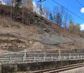
Senceive has been adapting its wireless monitoring solutions to help ensure the stability of railway earthworks slopes.
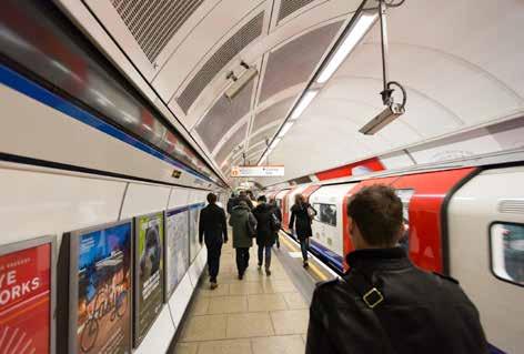
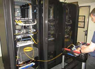
Growing demands for data mean that TfL’s Connect network requires an upgrade to satisfy requirements. 60| 29| Remote monitoring innovation to boost winter resilience
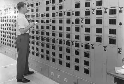
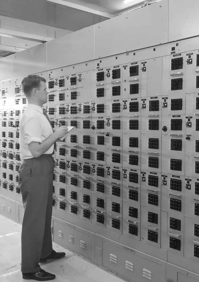
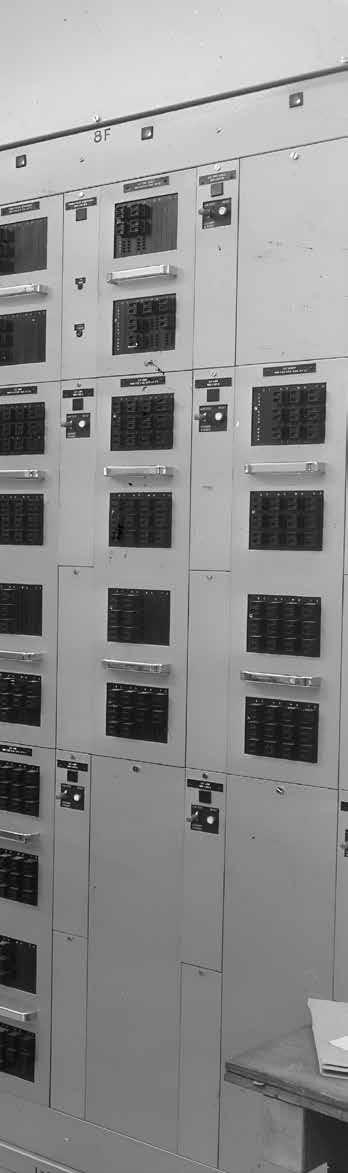
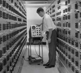
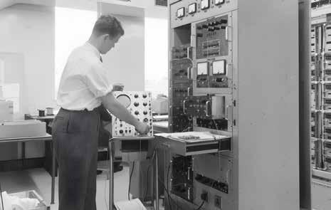
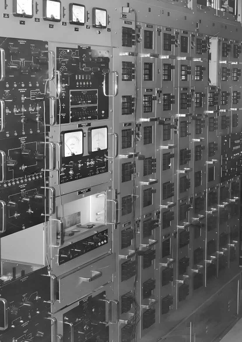
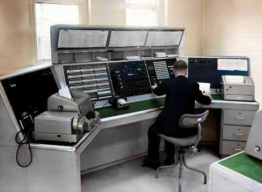
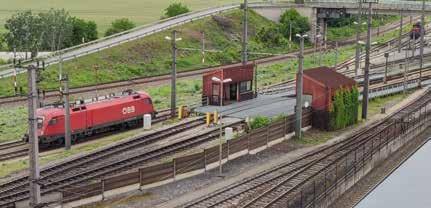
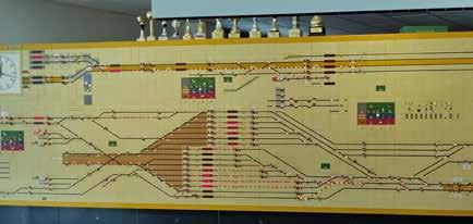
STRAD – an electronic data system ahead of its time Rail Engineer takes a look at an electronic teleprinter exchange that was revolutionary when introduced 60 years ago.
30| 34| Rail Reliability supports Class 458 fleet
In December 2020, Rail Reliability engaged with SWR to help with maintenance problems on its Class 458 fleet.
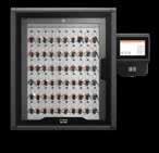
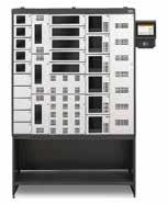
Traka: enhancing safety, wellbeing, and environmental health
Mike Hills highlights how advanced key and asset management solutions enhanced security, health, and sustainability.
ECDP: an update
David Fenner reports on Network Rail’s recent progress update on the East Coast Digital Programme.
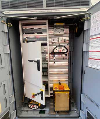
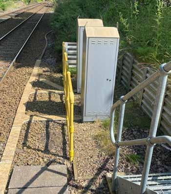
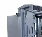
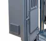
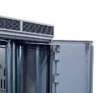
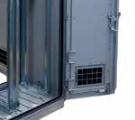
Equipment enclosures
Electronic equipment is increasingly located on platforms and trackside. Paul Darlington considers the options for housing it.
TPWS – a retrospective
David Fenner discusses the Train Protection and Warning System, rolled out when the Railway Safety Regulations 1999 came into force.
Demystifying the safe braking model
Malcolm Dobell unravels the secrets of the safe braking model and explains how it differs from traditional overlap calculations.
58|
Bluetooth Auracast
The latest development in Bluetooth technology is the introduction of Bluetooth Low Energy (LE) and Auracast™.
TfL Connect Network Upgrade
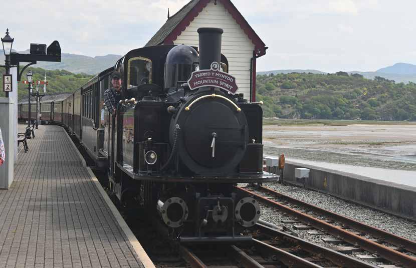
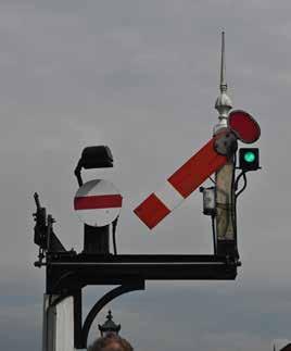
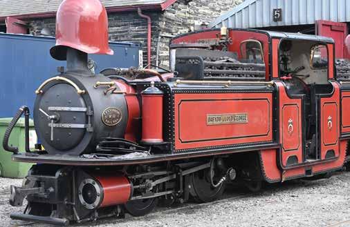
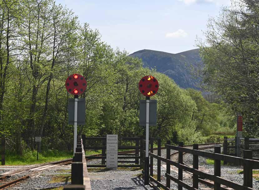
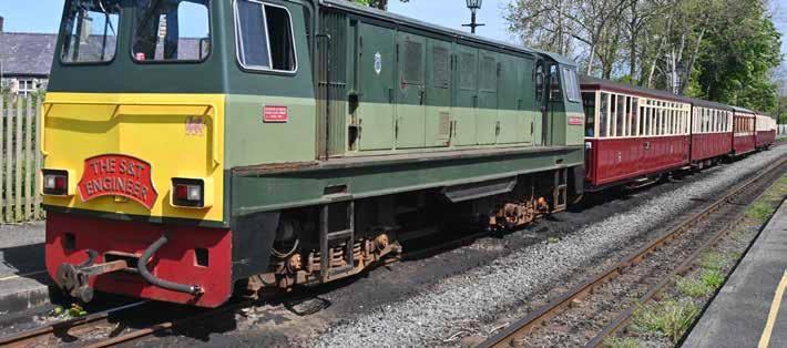
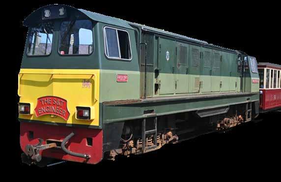
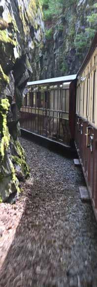
64| Signalling on the Ffestiniog and Welsh Highland Railways
Heritage railways boost local economies and preserve historic rolling stock, track, and signalling technologies. 68|
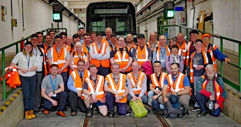
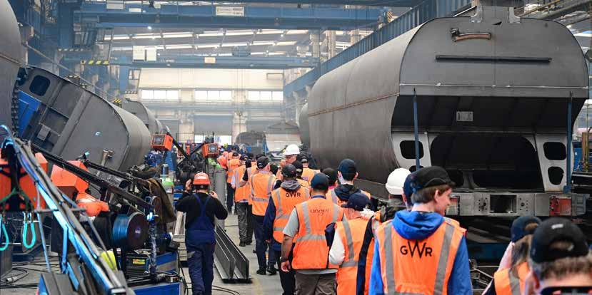
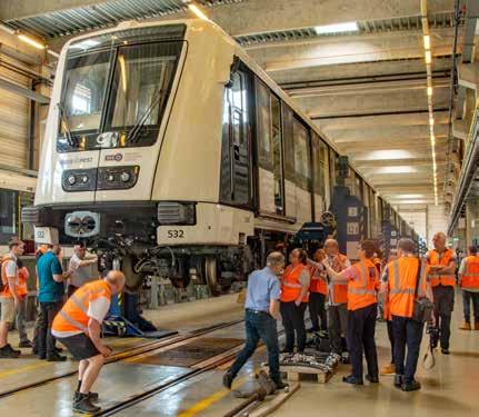
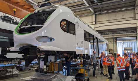
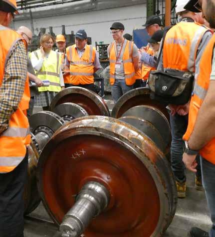
IMechE technical tour 2024
David Shirres and Malcolm Dobell join IMechE Railway Division’s eight-day, four-country, European tour.
TRU sustainability strategy
Anna Humphries, head of sustainability and social value at TRU, tells us more about the programme’s sustainability strategy.
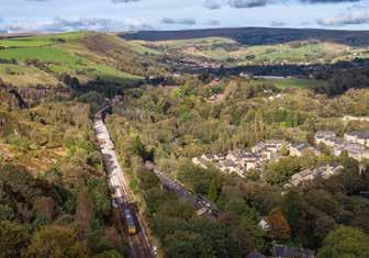
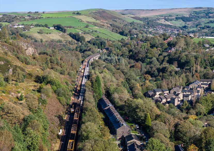
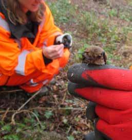
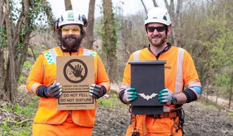
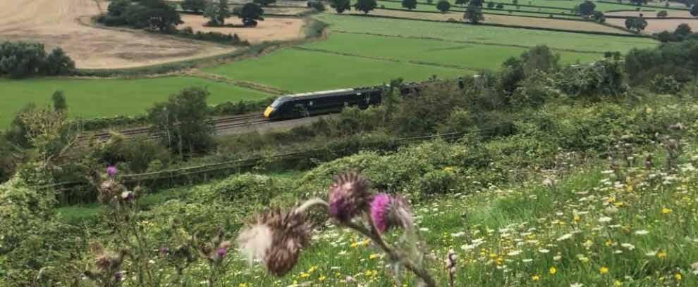
Biodiversity: a balancing act
The land around our railways provides a crucial sanctuary for plants and animals which must be protected.
ECONOMY GROWING THE EDITORIAL
All major political parties agree about the need to grow the economy, yet they differ on how this can be done. Some argue that tax cuts enable people to spend more and allow companies to retain more profits for reinvestment. However, overreliance on this policy can have dire economic consequence as was shown by the September 2022 mini budget.
Tax cuts are not mentioned in the Bank of England’s website explainer about how quickly an economy can grow. This states that economic growth requires three things: business investment in better ways of doing things, a skilled workforce, and high-quality infrastructure that makes transport and communication quick and cheap for businesses and workers.
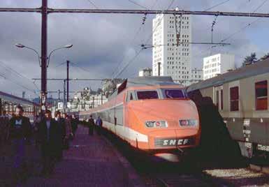
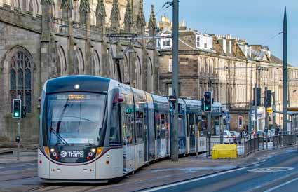
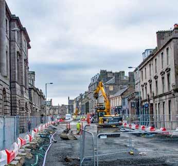
Despite its importance, UK infrastructure investment lags well behind the rest of world. In respect of rail investment, this is evident when travelling by rail in Europe. An obvious example is the continent’s high-speed network which saw its first line in 1981. Another is the Paris RER system which was inaugurated in 1977. This has three main-line underground tunnels connecting what were terminal stations. London’s equivalent, the single Elizabeth line, opened in 2022.
Yet there are signs that the new Labour Government would seem to recognise this deficiency. In her recent speech to the Labour Party Conference, Chancellor Rachel Reeves stressed that growth needs investment in new infrastructure and that “it’s time that the Treasury moved on from just counting the costs of investments, to recognising the benefits too.” Hopefully this indicates that she is considering changing the Treasury’s fiscal rules to allow more borrowing for investment.
This seems to be a change of approach from her July statement which cancelled unaffordable road and rail schemes costing £785 million after advising that the Government had inherited £22 billion of unfunded pledges. Hence, she said, “if we cannot afford it, we cannot do it” and that stressed that debt had to be reduced to get budget into balance.
As we report, the need for a steady rail investment pipeline is stressed in the Labour Party’s Rail and Urban Transport Review (RUTR) which considers how government could accelerate connectivity within
and between the UK’s key urban areas. This considered that the lack of a long-term plan and unprecedented ‘chop and change’ raises costs and deters investors. It also called for increased private sector investment in rail infrastructure.
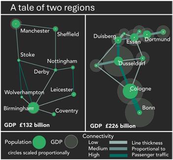
This call for increased private investment was echoed by a review led by David Higgins on behalf of the Mayors of West Midlands and Greater Manchester to enhance connectivity between their regions following the cancellation of HS2 phase 2. To do so, it highlighted the benefits of increased connectivity by comparing the GDP of Rhine/Rhur and Birmingham/Manchester/East Midlands regions. The report concludes that a new line is needed which should use the Parliamentary powers of the HS2 Phase 2a Act which expire in 2026.
It is to be hoped that the Government accepts this report’s recommendation and also authorises tunnelling to Euston, the need for which is highlighted by crowding at Euston station.
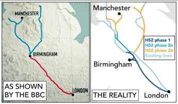
Unfortunately, the case for extending the currently authorised HS2 works was not helped by a recent BBC Panorama programme. This was unbalanced as it only considered the excessive costs of HS2 with minimal consideration of its benefits. Its HS2 map perpetuated
the misconception that phase 1 only goes to Birmingham as it did not show phase 1 to be a by-pass for the southern end of the WCML with a spur to Birmingham for only a third of HS2 trains. Such poor reporting by the BBC’s flagship current affairs programme is profoundly disappointing.
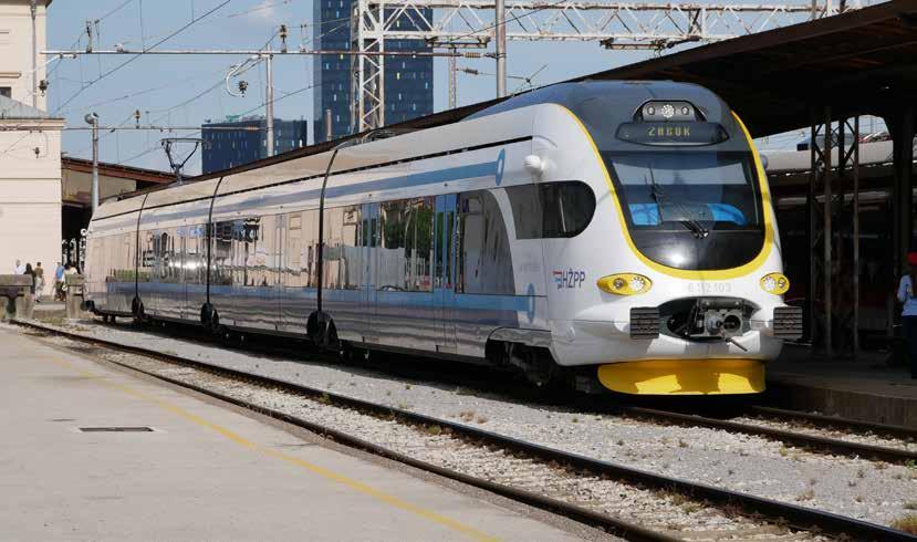
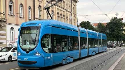
Malcolm Dobell has been travelling to Europe to see, amongst other things, the impressive tram networks in Vienna, Budapest and Zagreb as part of the IMechE’s railway technical tour. This tour included a visit to the Semmering base tunnel works. As Malcolm describes, this €4 billion project will reduce the journey time between Vienna and Graz by 30 minutes when it opens in 2028.
obsolete and unable to satisfy the everincreasing demand for data transmission. Also now obsolete is the STRAD railway electronic data comms system, although as we describe when it was introduced it was well ahead of its time.
This month’s magazine has a wide variety of articles for its signalling and telecommunication focus. David Fenner’s Train Protection and Warning System (TPWS) retrospective marks 20 years since this project was delivered following which there has not been a fatal train accident due to a signal passed at danger. David also highlights the challenges of the East Coast Digital Programme (ECDP)’s implementation of ETCS on a mixed traffic railway and explains its extended timeframes.
As digital signalling gives a continuous in-cab display of a train’s maximum safe speed, it must also continuously compute the train’s braking distance. As we show, this is particularly complex for communication-based train control systems (CBTC). We also describe the various signalling systems in use on the heritage narrow-gauge Ffestiniog and Welsh Highland Railways (WHR). Interestingly, this includes ETCS control of the crossing where the WHR crosses Network Rail’s Cambrian Coast line.
Telecoms are featured in articles by Paul Darlington on Auracast, the latest Bluetooth development, and Clive Kessell on the upgrade of Transport for London’s (TfL) 25-year-old Connect system. This is now
DAVID SHIRRES
RAIL ENGINEER EDITOR
The ORR gave the new Class 805 Avanti unit authorisation to operate in December. Six months later it issued Avanti with an improvement notice as the ORR now considers that operating these trains breaches safety legislation. We explain the background to this curious tale. In contrast, the Southwestern Railway’s (SWR) Class 458 units are approaching the end of their service life, with resultant obsolescence and material supply issues. We describe how SWR engaged Rail Reliability to overcome these issues.
Testing both new trains and novel infrastructure on top of a Welsh hill is the vision of the Global Centre of Rail Excellence (GCRE). However, £300 million of private finance needs to be raised to achieve this vision. As the annual global rolling stock market is worth £50 billion, GCRE is hopeful about raising this sum. We wish them well.
An example of novel infrastructure is the ‘Beacon’ footbridge. As Bob Wright describes, this is a next-generation footbridge developed by Network Rail.
‘Our guiding compass’ is the Transpennine Route Upgrade’s (TRU) sustainability strategy which aims to benefit local communities. We describe its outcomebased approach to achieving this objective. Along most railway lines is a ‘green corridor’ which provides an ecosystem relatively unharmed by mankind’s excesses. Matt Atkins explains how Network Rail is safeguarding its biodiversity while at the same time ensuring that vegetation presents no risk to the rail infrastructure.
As always, our features show how engineers are providing a safe, efficient railway. Throughout history, railways have stimulated economic development. With the required investment, they will stimulate the economic growth to which the government is committed.
Editor
David Shirres
david.shirres@railengineer.co.uk
Production Editor
Matt Atkins matt@rail-media.com
Production and design Adam O’Connor adam@rail-media.com
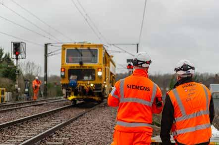
In December, the Labour Party commissioned a Rail and Urban Transport Review (RUTR) to examine how a future government could accelerate connectivity within and between the UK’s key urban areas. This was led by Juergen Maier CBE, former Siemens CEO and vice chair of the Northern Powerhouse Partnership. He was supported by nine senior professionals from industry, devolved regional bodies, and the Trades Union Congress.
The RUTR was published in August after considering over 100 written submissions. This feedback showed that the opportunity public transport presents to boost economic growth, green passenger travel, and freight, and to boost social mobility is massively underestimated. It was considered that this significant level of engagement enabled the review panel to produce “an ambitious but realistic blueprint for delivering a step-change in rail and urban transport infrastructure.”
It was suggested that the lack of a long-term plan and recent unprecedented ‘chop and change’ created significant ambiguity, raised costs, and held back investment. Yet despite this, with current low confidence in public transport, both investors and passengers have a strong desire to see significant improvement.
Long-term vision needed
The RUTR calls for government to set a goal of doubling mode share of rail within a decade. As a medium term objective, it also requires the production of a Transport Strategy for England (TSE) which considers cross border links and is linked to the UK industrial strategy. This TSE also needs to be supported by sub-national transport strategies produced by regional bodies who should have devolved five-year transport budgets.
It also notes how clear, steady investment pipelines can reduce construction costs over time as was the case for high speed rail construction in France and Spain. In part, this was due to the elimination of boom-and-bust procurement. Such pipelines also help develop the capability and capacity of the rail supply chain as well as establishing crucial investor trust and confidence. This RUTR considers the Rail Minister should be the explicit responsibility for the development of the rail supply chain.
Prototype French high speed train seen here in 1979, France opened its first high-speed line in 1981.
Accelerating delivery
As the RUTR shows, project timescales could be reduced by clearer responsibility for delivery as there are too many organisations responsible for overseeing projects. This creates a burden that does not add value. It also considers that there have been disproportionate delays due to government funding decisions. Furthermore, current project appraisal guidance needs to be reviewed to recognise that transport has far reaching social benefits beyond cost benefits and reduced journey times.
In this respect the RUTR considers that there is much to be gained from the Welsh Government’s new appraisal methodology. This places less emphasis on the use of Benefit-Cost Ratios (BCRs), and more on wellbeing appraisal based on the ambitions and targets in the Wales Transport Strategy. The Welsh Government believes that transport planning is about designing good programmes and projects that meet the needs of people in Wales. This is assessed by robust qualitative and quantitative evidence, including the project’s contribution to modal shift targets.
RUTR notes that the greatest opportunity for project acceleration and cost savings is during the first 10% of project lifecycle to ensure the right foundation for capital spending ahead of investment decisions. It describes a nine-step approach developed by Arup that is claimed to reduce cost by 20% and deliver 25% faster.
5 Parallel working, integrated consent and procurement strategies
6 Accessible stakeholder engagement and pragmatic agreement
Delivery 7 Early enabling and environmental works
8 ‘One team’ working, shared risk management with social value at heart
9 Systems integration, operational readiness with digital backbone
PHOTO: DAVID SHIRRES
Other identified issues that need to be addressed to more rapidly improve public transport are reforms to bus and rail services to accelerate urban transport delivery, planning process improvements, and greater collaboration between regions, for example in respect of additional capacity between Manchester and Birmingham.
Private finance
The necessary improvements require both public and private finance. Two ways in which the private sector can invest in transport infrastructure are suggested. One is delivery partnerships, where the private sector helps deliver the project to make a direct return on its investment. Another is capturing the financial benefits created by transport investment, for example boosting revenue or asset values.
The RUTR provides a case study about financing HSL Zuid, a 96km high speed rail line between Schiphol Airport in Amsterdam and the Belgian border. This was constructed under a Public Private Partnership in which the construction consortium has to design, construct, finance, and maintain this high speed line for 25 years. In return the Dutch state pays an annual fee based on actual infrastructure availability.
Another possibility of generating private finance is land value capture. New transport infrastructure invariably increases the value of adjacent developments. Land value capture seeks to raise funds from developers for new rail infrastructure before schemes are approved.
The RUTR recommends that the British Infrastructure Council should develop a new approach to private finance by the end of 2024.
Getting structures right
Reforms to key bodies are required to accelerate project delivery. In particular, the Nationally Significant Infrastructure Projects (NSIP), Transport and Works Act, and Environmental Impact Assessment regimes need to be reviewed to enable faster and more effective project delivery.
The RUTR considers that the new National Infrastructure and Service Transformation Authority (NISTA) should advise national and regional partners on the more effective delivery of transport infrastructure and ensure government departments work together to deliver local needs. Furthermore, the newly proposed Industrial Strategy Council needs to be expanded to include supply chains for key national infrastructure projects. In addition, TSE schemes need to have a clear pipeline of priority strategic projects which should be published annually.
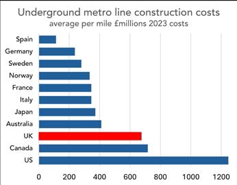
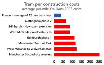
UK has particularly high infrastructure costs as shown by these RUTR charts.
PHOTO: DAVID SHIRRES
PHOTO: DAVID SHIRRES
UK has particularly high infrastructure costs as shown by these RUTR charts.
Listening to workforce and users
A key RUTR theme is that the views of transport users and the workforce need to be effectively incorporated in transport planning.
For this reason, it is recommended that the customerfocused elements of the Office of Road and Rail (ORR), the Rail Ombudsman, Bus Users, and Transport Focus should be combined into one organisation with the ORR’s health, safety, and performance regulatory powers remaining separate.
In addition, a transport citizens panel should be formed as part of the consultation process for transport infrastructure design together with strengthening the role of the existing Disabled Persons Transport Advisory Committee. Furthermore, the importance of constructive industrial relations across rail and urban transport infrastructure needs to be recognised.
Challenges
The feedback received by the RUTR identified three issues that impact the delivery of transport projects:
1. Lack of a transport strategy – There was a near-universal view that the lack of a coherent transport strategy is a critical barrier to progress. As a result, individual projects are assessed on their own merits rather than having a comprehensive programme to achieve strategic objectives. This leads to an escalation in delivery costs, lack of investor confidence, a failure to address passengers and freight growth, as well as preventing the supply chain developing expertise and resources. It also makes major projects vulnerable to political shifts.
2. Failure to get basics right and put customer first – Regional UK cities underperform European cities in respect of integrated ticketing and fares. The population share that can access the city centre in 30 minutes is also well below the European average. This negatively affects labour markets. The new government needs to overcome barriers to integrated transport including bus deregulation and rail privatisation which has resulted in poor connections between inter urban rail and urban public transport.
3. Deep and growing productivity gap – London is 26% more productive than UK average. High quality affordable transport is essential if this disparity is to be reduced. Moreover, transport investment signals confidence and serves as a focal point for other investment. The productivity impact of stronger connectivity through the introduction of inter-city high speed rail is evident by the economic growth in European secondary-city regions. As an example, cities like Düsseldorf, Cologne, and Bonn have productivity levels significantly above the German average.
4. Loss of expertise – A growing tide of expertise is leaving the UK to countries that better recognise the benefits of rail and urban transport. Britain is thus losing personnel to its global competitors who could otherwise be helping strengthen the economy.
Resetting transport
High quality transport is critical for businesses to move goods, forge new connections, create opportunities, and generate wealth. Thus, rail and urban transport are central to the challenge of driving economic growth. Poor transport also adversely affects social, environmental, and economic outcomes. Yet compared with continental Europe, the UK has poor connectivity within and between city regions where labour markets are too small to create a proper counterweight for London. Hence, if our cities and regions are to thrive, there is an urgent need to improve rail and urban transport.
Furthermore, the RUTR found evidence that some parts of the supply chain are looking at opportunities elsewhere in the world. Hence without a firm commitment to act soon, there is a risk that the UK will lose the resources and competence needed to deliver its transport plans.
The RUTR panel therefore considers that time is of the essence and hopes that the new Government will act swiftly to adopt the proposals in its report which are an opportunity for a major reset of rail and urban transport investment.
Prime Minister hosts his first Cabinet at
Downing Street.
PHOTO: LAUREN HURLEY/NO 10 DOWNING STREET
RailStaff has been
As
»
»
»
»
We
Calling for connectivity Part 2: The Mayors’ plan
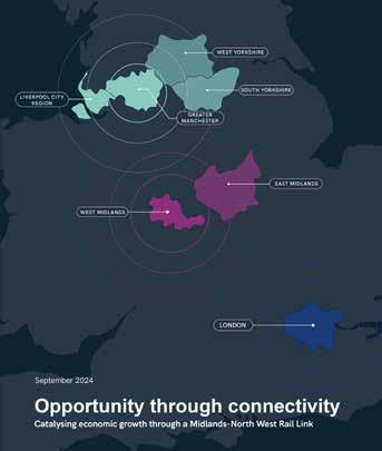
Less than a month after the publication of the Rail and Urban Transport Review (RUTR) came the ‘Opportunity through Connectivity’ (OtC) report which was published on 13 September. This reinforces the RUTR’s conclusions by emphasising the importance of rail connectivity, the need for more effective project management, and better use of private finance.
However, while the RUTR’s remit took a strategic overview, the OtC was specifically concerned with improving connectivity between the Midlands and North West of England. It was commissioned by the mayors of West Midlands and Greater Manchester to explore options to enhance connectivity between these regions following the cancellation of HS2 phase 2 in October. David Higgins, formerly Chairman of HS2, was asked to review the impacts of this decision and opportunities for moving forward. In doing so he was supported by a private sector team led by Arup and supported by Addleshaw Goddard, Arcadis, Dragados, EY, Mace, and Skanska.
Something must be done
OtC explains why doing nothing north of the proposed termination of HS2 at Handscare is not sustainable. Passenger demand on the West Coast Main Line (WCML) has more than doubled since the 2000s to roughly 35 million intercity journeys per year. This makes it one of the busiest rail lines in Europe. Moreover, parts of the WCML carry 60 freight trains per day and are forecast to carry double this number. The OtC report is confident that within the next decade travel demand on the London-Manchester corridor will exceed the maximum capacity of the line.
The report is also clear on how high quality transport infrastructure stimulates economic activity. It compares the German RhineRhur regions with Greater Manchester, South Yorkshire, and the Midlands. Both these regions have a population of 11 to 13 million yet the German region, which has high-speed rail links, has a GDP of £226 billion, compared with £132 billion for the UK region. Bringing the Manchester and Birmingham city regions up to UK average productivity would add £43 billion annually to the UK economy.
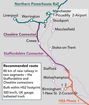
MNWRL
Having considered various options, OtC considers that the best way forward is a new Midlands-North West Rail Link (MNWRL). The comprises two new lines delivered in a staged manner. The first is the Staffordshire Connector which would follow the route of HS2 phase 2a which already has parliamentary powers. The second new line is the Cheshire Connector which would run from Crewe to a point on the proposed Northern Powerhouse Rail (NPR) line between Warrington and Manchester. Using NPR to reach Manchester will enhance the business case of both schemes.
The report stresses that to avoid abortive costs the Cheshire Connector design needs to be urgently progressed to inform NPR design. Work would also be required at Crewe station in accordance with the requirements of Network Rail and local stakeholders.
These new lines would be designed for 300km/h, built to UK loading gauge, and have ballasted track. This compares with HS2’s continental loading gauge, slab track, and 360 - 400km/h speed. Together with improved project management, it is considered that MNWRL will be 60-75% the cost of HS2 phase 2.
With HS2 phase 2a’s parliamentary powers expiring in February 2026, key strategic decisions are needed by early 2025. Furthermore, to minimise capital costs, greater engagement of private sector expertise is needed to drive efficiency. The report has examples of how this has been done in Europe. For example, the Tours-Bordeaux high-speed line was constructed by a consortium which owns, maintains, and operates the line over a 50-year concession period.
The OtC report offers an achievable solution which will make best use of otherwise wasted HS2 costs. This needs to be delivered before the quality of connectivity worsens as travel demand grows to create a major barrier to economic growth.
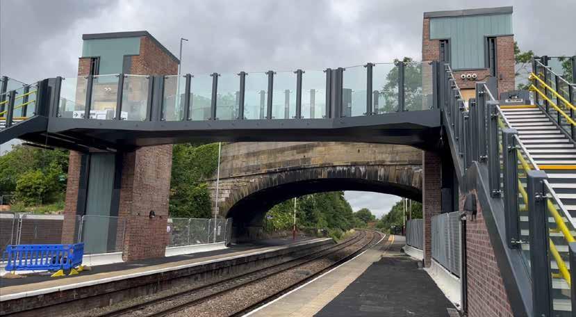
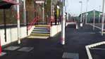
A 'Beacon' at Garforth
Garforth station’s new footbridge opened in July, replacing a 190-year-old North Eastern Railway cast iron structure. An additional link span also connects the station to Aberford Road. Work to complete the lifts is now almost complete, and this will give rail passengers a safe, step-free option at the station for the first time.
Many stations have had their footbridges replaced, but this structure is a ‘Beacon’ bridge, one of Network Rail’s new generation of designs first devised in 2018 as part of its government-funded ‘Access for All Programme’ during Control Period 6. This provides obstacle free, accessible routes to and between platforms. Accessibility here benefits everyone –people with health conditions or impairments, people with children, heavy luggage or shopping, and some older people. It’s also good for the economy and means fewer car journeys, less congestion, and fewer carbon emissions.
Next generation bridges
In 2019, Network Rail revealed three concept designs for next generation railway footbridges blending forward-thinking architecture with creative engineering, and distinctive identities that would gradually replace current standards and historic structures in the future.
The three concepts were:
» The ‘Beacon’ – a fully glazed bridge featuring lantern-topped lift towers and a dynamic articulated engineered structure. The type selected for Garforth.
» The ‘Ribbon’ – an update of the classic arched footbridge with an elegant floating canopy spanning the track, featuring 30-degree lift and stair rotations.
» The ‘Frame’ – a radical expression of minimalism that offers a range of flexible, functional configurations.
Network Rail’s design development process included engaging with passengers, sharing these three designs using Arki augmented reality on smartphone devices and exploring these 3D models providing detailed visualisations of the architects’ designs.
Sahar Fikouhi of Darf Design, and developer of Arki, explained that: “It’s very rare for the public to have this access to genuine architects’ drawings and this is one of the first examples of future projects. The app is helping to democratise the way structures are designed and built by giving the public this access at early stages of design selection.”
During this engagement it was discovered that standard enclosed footbridges made
some passengers feel unsafe, especially while travelling alone and particularly at night. As a result, a passenger security feature of the ‘Beacon’ bridge is side panels made from toughened glass. This was an important design consideration so that all bridge users can see if other people are also using the bridge or staircases.
The £6 million contract to reconstruct the Garforth bridge was awarded to AmcoGiffen.
The ‘Beacon’ footbridge gets its name from the striking design of the illuminated glazed tops of its two lift shafts. It was developed and designed by AmcoGiffen’s design and engineering, steel fabrication, and construction teams in close collaboration with its supply partners and Network Rail, building on the earlier concept design.
AmcoGiffen’s in-house steel fabrication team constructed the main elements of lift shafts, staircases, and main deck for the new structure at their base in Barnsley. Due to its size, the main deck was transported to the site under police escort and was lifted into place using a 350-tonne crane during rules of the route possessions.
Historically significant
Removing the old and fragile cast iron arched footbridge would be a challenge within
the limited available time on the busy Leeds to Hull route. The design team proposed a temporary support frame to cradle and stabilise the structure during the lift. The scaffold tube and structural steel cradle was craned onto the platform beside the bridge and winched into position on rollers within steel channels. This was then braced against the arch, and the structure and temporary works craned out together.
This proved to be a success, and thanks to a £25,000 Railway Heritage Trust grant, the historically significant structure has been transported to the Bredgar & Wormshill Light Railway, in Kent, for restoration and reuse.
Peter Laws, Framework director for AmcoGiffen said: “This milestone is a significant achievement for our team, our supply chain and our partners at Network Rail. The successful installation of the main span is the final major structural element bringing us closer to completion.
The unique ‘Beacon’ design with its dual aspect lifts, will undoubtedly transform the station, creating improved accessibility and a better experience for passengers and we look forward to seeing the positive impact it will have for the community of Garforth.”
PHOTO: NETWORK RAIL
The curious case of the Class 805 improvement notice
The Health and Safety at Work Act gives inspectors powers to issue prohibition and improvement notices. Prohibition notices are issued when it is considered necessary to stop an activity that involves risk of serious personal injury. Such notices must state the cause of this risk and the legislation that has been breached. When an improvement notice is issued, the inspector must specify which legislation has been breached and specify a time for compliance. Improvement notices are not required to state the risk associated with the legislative non-compliance.
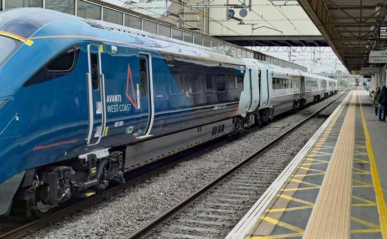
In August 2024, the Office of Road and Rail (ORR) had issued Avanti West Coast (AWC) with an improvement notice in respect of the operation of its new Class 805 which had received authorisation to operate from the ORR in December 2023. AWC has appealed against the issue of this notice which as a result has been suspended during the appeal period.
Authorisation to operate
The documentation submitted to the ORR to receive authorisation to operate the Class 805 includes a safety assessment report. This contained a risk assessment undertaken in accordance with the common safety method (CSM). This is a rigorous hazard identification and risk assessment process as specified in the relevant legislation. For each identified hazard, an assessment is required of whether it is broadly acceptable and, if so, a justification for this decision. If not, the risk from the hazard needs to be estimated and evaluated to specify the required safety controls. The ORR authorises a new train to operate after it has reviewed the required documentation and found it to be satisfactory.
So why, eight months after it accepted the Class 805’s safety assessment report, does the ORR now consider that the operation of these units breaches legislation? Although the improvement notice specifies which legislation has been
breached, this is not currently in the public domain as AWC has appealed against the notice. When asked to comment, the ORR provided the following statement:
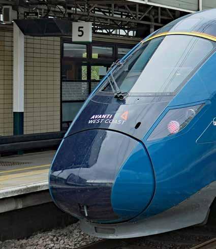
"ORR has issued an improvement notice to Avanti West Coast (AWC) because, unlike existing trains they are replacing, the new Class 805 trains are not fitted with an automatic speed supervision system."
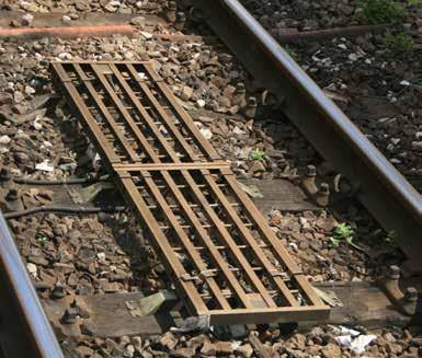
TASS
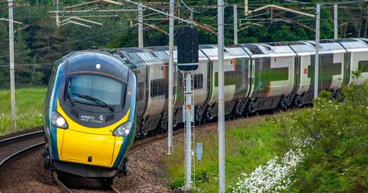
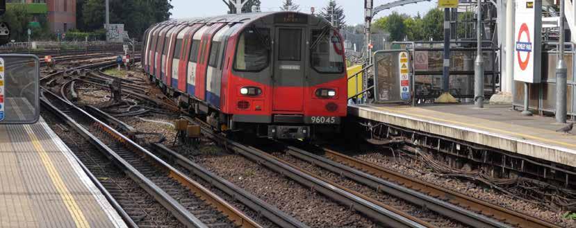
The Class 805 units are replacing Class 221 diesel units. Like the Class 390 ‘Pendolino’ trains, the Class 221 units are tilting trains that operate on the West Coast Main Line (WCML) and
PHOTO: DAVID SHIRRES
PHOTO: MALCOLM DOBELL
are fitted with a Tilt Authorisation and Speed Supervision (TASS) system. This has balises on the track that send signals to the Class 221 and 390 units to manage their speed and tilting. Due to their ability to tilt, the units can run around curves at up to 125mph. The Class 805 units normally operate on the south end of the WCML where non-tilting trains are limited to a maximum of 110mph.
Although TASS was installed to enable operation of the tilt mechanism, it also provides an automatic speed supervision system, a form of continuous speed supervision unlike the intermitted approach of the Train Protection Warning System. Hence it could be considered that TASS provides a greater level of safety. Readers can judge for themselves the extent to which TASS reduces risk reduction from the information below.
The new Class 397 units operated by TransPennine Express (TPE) on the WCML are not fitted with TASS and are not the subject of an improvement notice. This shows that the ORR’s concerns about fitting TASS to new trains solely relate to AWC operations as TPE drivers do not drive at the higher curving speeds of tilting trains. Furthermore, as AWC drivers will now alternate between TASS-fitted and non-TASS-fitted trains there is a possibility of an overspeed if, when driving a Class 805, drivers forget that it is not TASS fitted.
Level of risk
The reason that tilting trains can operate around curves at such higher speeds is that, for the comfort and safety of those inside the train, tilt reduces the centripetal forces on them as the train goes around a curve. If a non-tilting train goes around a curve at 125mph instead of 110mph, people and objects inside the train will experience a 29% increase in centripetal force as this is proportional to speed squared.
However, there is no risk of the train coming off the track as a result of such overspeeding as tilt does not affect lateral track forces. Hence, the curving forces on the track for a Class 805 at 125mph would be very similar to those from a tilting Class 221 at 125mph.
If there was any risk of such an overspeed resulting in a derailment, the ORR would have issued a prohibition notice rather than an improvement notice.
Thus, the risk of a Class 805 overspeeding because it is not fitted with TASS is to those inside the train. This hazard should have been identified with the level of risk and required safety control shown in the CSM risk assessment. Although Rail Engineer asked the ORR and AWC whether this hazard had been identified, neither were prepared to comment on this issue.
A change of mind?
The issue of an improvement notice some months after authorising the Class 805s to enter service shows that the ORR has either:
1. Now identified that the overspeeding hazard was missing from the CSM risk assessment and is retrospectively rectifying this deficiency by the issue of an improvement notice.
2. Changed its mind and no longer considers that the overspeeding risk assessment shows that the specified controls manage this risk to a level that is as low as is reasonably practicable. Thus, it would seem that the ORR now considers AWC’s operation of Class 805 units now breaches the Health and Safety at Work Act.
As shown by its statement, the ORR’s particular concern is that a safety control (TASS) fitted to AWC’s existing fleet is not fitted to its Class 805 trains. Hence it would seem that compliance with the improvement notice, which is reported to have a two-year compliance period, requires the Class 805 to be retrospectively fitted with TASS or some other form of continuous speed supervision. As these units are ETCS ready, this may only require a software fix for the trains to receive TASS balise signals. If hardware modifications are required, the cost of compliance with the improvement notice could be significant.
As can be seen, the ORR’s issue of an improvement notice for the operation of a train that it has recently granted authority to operate raises various issues. It will be interesting to see how this curious case is resolved.
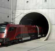
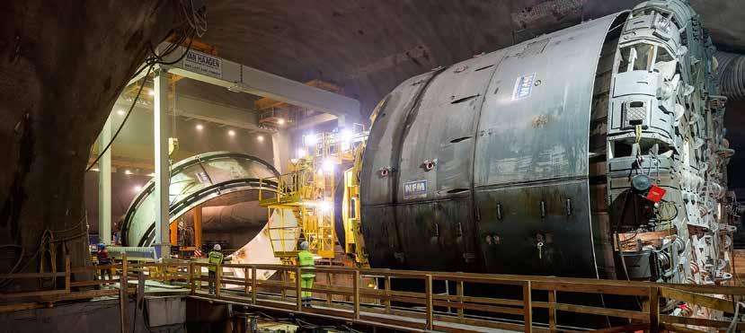
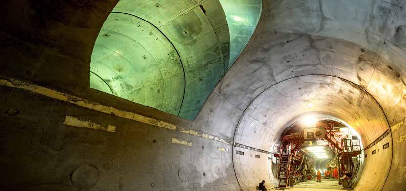
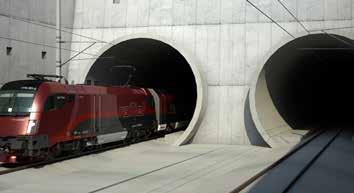
The Semmering Base Tunnel: overcoming the Alps
One of the highlights of the Institution of Mechanical Engineers Eastern European Rail Tour in May/June 2024 was a journey from Austria’s Vienna Hauptbahnhof over the Semmering pass to Mürzzuschlag Bahnhof for a visit to the offices and southern portal of the Semmering base tunnel which is under construction.
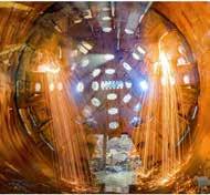
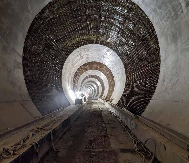
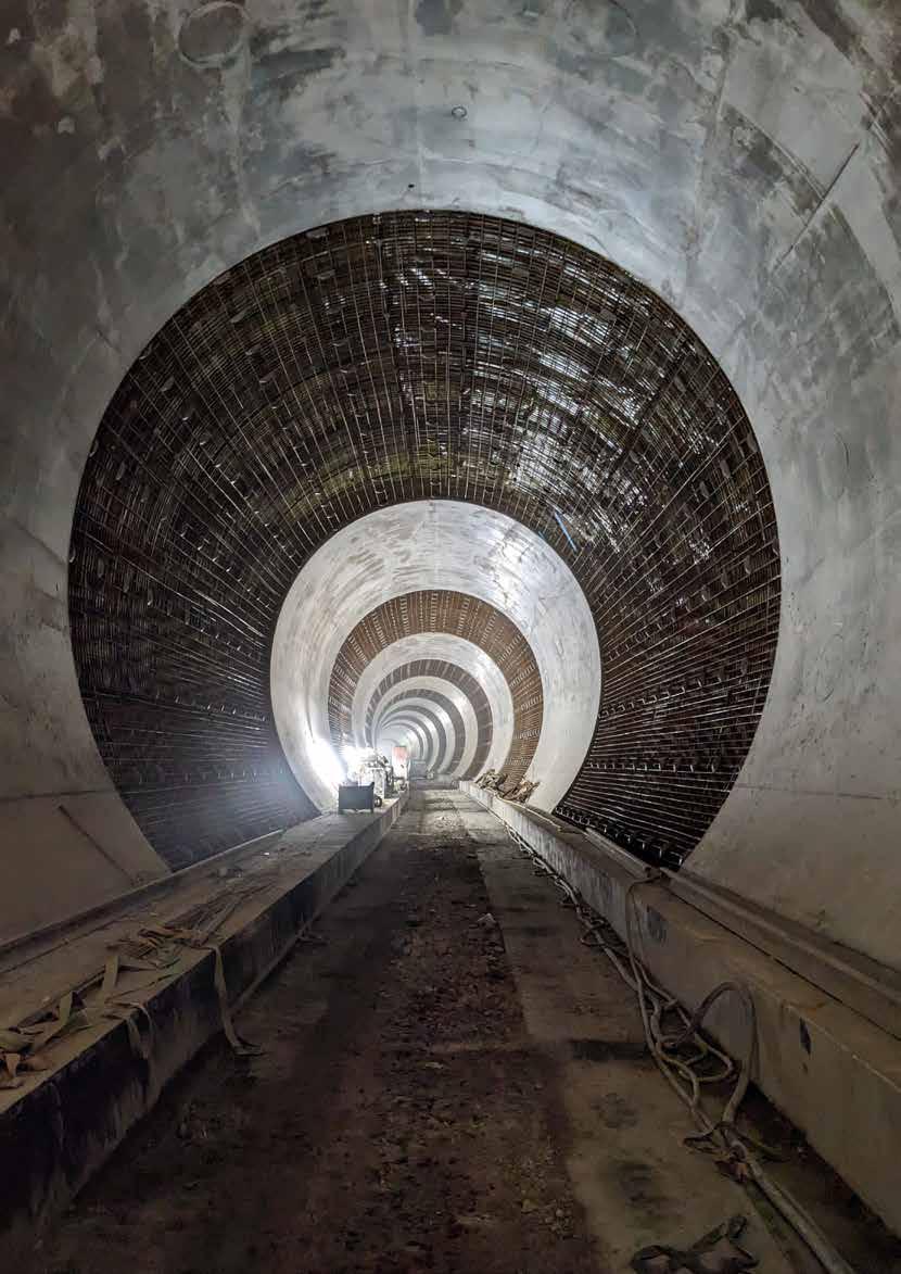
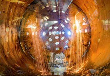
Tunnel beyond Mürzzuschlag portal, lining in progress with steel reinforcement mesh sections over the the yellow waterproof membrane behind the mesh. (Jonathan Prince)
When European railways were developed in the 19th century, civil engineers had to overcome the barrier of the Alps to deliver north-south links in Austria as well as in other Alpine countries. These early lines were characterised by long, and often heavily curved climbs up to passes or comparatively short tunnels
though mountains. Ruling speed limits were typically between 50km/h and 70km/h. All of this was challenging for early locomotives and the descents challenged early braking systems.
Today’s trains are more capable but, as both passenger and freight train speeds have increased, these routes have
imposed time and capacity constraints. Tunnelling techniques have improved immeasurably since then and many railway administrations have built or are building socalled base tunnels allowing much higher speeds with smaller climbs and many fewer curves, although the tunnels are much longer. The Swiss Lötschberg base tunnel was the first, built over 20 years ago. However, the high cost resulted in a 20-year gap between the completion of tunnelling and its fitting out for double track operation throughout.
MALCOLM DOBELL
Reducing journey times
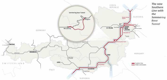
The Semmering base tunnel, an ÖBB-Infrastruktur AG (Austrian state railway infrastructure company) project, is being built on the ‘The Southern Line’ between Vienna, Graz, and Klangenfurt as part of an EU transport plan to improve north-south rail services though the Austrian Alps. It is expected to reduce the journey time between Vienna and Graz by 30 minutes and will benefit the approximately 3.5 million people who live around this route.
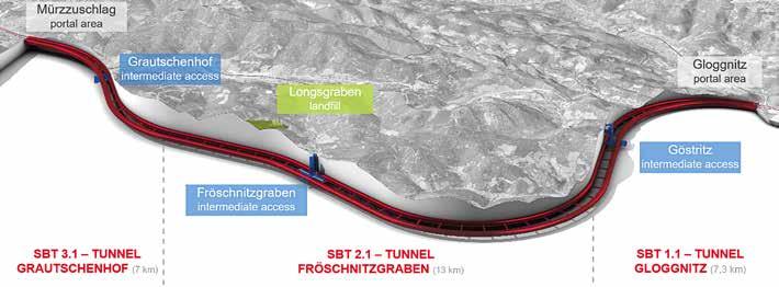
The tunnel will be 27.3km long running between Gloggnitz and Mürzzuschlag and cutting off the lengthy, steep, and curved route previously above. It is not taking a straight line partly
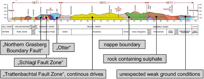
to provide a reasonable 0.8% gradient to cover the 280-metre height difference between the two stations and partly to avoid the worst rock formations and fault lines on straighter routes. Several options were explored and around 280 core drillings with a combined depth of about 41km were made around the Semmering area to explore rock composition. The most northern option was discarded quite early as it would have influenced water flow into Vienna’s water supply. The project brochure suggested that all this exploration allowed the ideal route to be chosen, but the tour group were left in no doubt that this amounted to the least worst option.
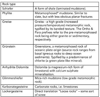
The various rock types are shown in the diagram below which highlights fault lines
and rock types. There is more information on rock types in the panel.
Anyone used to tunnels in the UK, built by setting off a tunnel boring machine (TBM) from one end of a tunnel to the other, would be amazed at what has been involved. There were many problems when mining through faults in the rock, and what might look like a straight section blasted through the rock could soon become misshapen as the blasting released locked in stresses, leading to rework.
Construction
The tunnel has been constructed from five sites/ access points. Alongside reconfiguring the track layout and constructing portals at Gloggnitz and
Location of the Semmering Base tunnel on the ViennaGraz-Klagenfurt route. The enlargement shows the line of the new tunnel in red.
Longitudinal section though tunnelling route showing different rock formations and fault lines.
The contract lots, five access points, and landfill site described below.
Mürzzuschlag, three other sites at Göstritz (northern end), Fröschnitzgraben (approximately the middle), and Grautschenhof (southern end) were set up. Each end of the tunnel has seen extensive
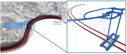
bores with 16 cross passages started construction by conventional mining in 2015 and is due for completion in 2028. Intermediate access has been provided at Göstritz. This site required one kilometre of
Diagram showing Gloggnitz access.
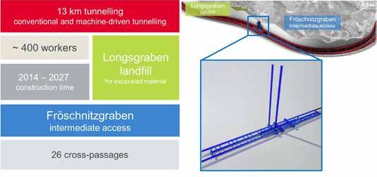
Fröschnitzgraben: central safety cavern area and construction/ventilation shafts.
works to remodel the tracks and stations together with constructing the portals and the initial tunnels, mostly using rock mining methods.
The main construction was let in three lots:
Construction section SBT1.1 Gloggnitz Tunnel. This section of two 4.6km long tunnel
temporary tunnel including two 250-metre-deep vertical shafts with logistics caverns at the top and bottom of the shafts. Two tunnels, approximately 1.6km length are being excavated in each direction from the bottom caverns. This involved dealing with groundwater ingress of up to 100 litres/second and,
until the area was sealed, the water had to be pumped out continuously.
Construction section SBT 2.1 Fröschnitzgraben tunnel. The middle section through Fröschnitzgraben is a 13km section with approximately 4.3km of twin tunnel using mining (drill and blast). The emergency refuge areas are approximately 950 metres long with several cross passages and approximately 8.2km of twin tunnel being built with two tunnel boring machines (TBM). Work started in 2014 and is due for completion in 2027. Access to this section was provided through two 400-metre-deep shafts, 8 metres and 11 metres in diameter. At the bottom of the shafts, 950-metre-long emergency refuge caverns were constructed into which sections of TBM were lowered for assembly underground.
The TBMs were removed in sections at the end of construction. There was significant ingress of water in some parts of the mining
tunnelling section. When completed, the cavern at the bottom of these deep shafts will have means for emergency intervention and will have fresh air pumped in through one shaft and foul air or possible smoke exhausted via the other. All this will be provided by what was modestly described as ‘a large fan system’. Spoil
Assembly (above) and disassembly (inset) of TBM in Fröschnitzgraben central cavern.
from construction was removed via the 400-metre shafts and deposited in a landfill at Longsgraben where the local population has been involved in landscaping the site.
Construction section SBT 3.1 Grautschenhof tunnel. Work started on this section in 2016 and is due for completion in 2026. It involves twin tunnels, both 7km long with 16 cross passages. From two temporary 100-metre-deep shafts, four tunnel drives are in progress using drill and blast excavation.
Fit out and system commissioning
Construction started in 2012 and is expected to be complete in time for traffic to start in
2029. The original cost was estimated at €3 billion but, after difficulties caused by Covid, the geology of the site, and global inflation, the cost has increased by approximately €1 billion.
Our tour group was unexpectedly given the privilege of visiting the Mürzzuschlag portal and of walking along the tunnel for approximately 100 metres where we observed teams installing waterproofing sheets and steel reinforcement mesh prior to the in-situ casting of a smooth concrete lining.
We were able to see the foundation of the track bed and the channels that will be used to direct water from the inevitable leaks. For your writer who is used to the London Underground, the tunnel seemed absolutely huge. This is necessary, of course, to accommodate European-gauge double deck coaches.
Work has continued since the visit, of course, and recently ÖBB-Infrastruktur announced that on 11 September the last break through was made in the first tube in the Gloggnitz construction section, meaning that Gloggnitz
and Mürzzuschlag are now completely connected underground. The report added that work on the second tube is expected to be completed in the first quarter of 2025, when tunnelling will be completely finished.
Finally, in case anyone was in any doubt, ÖBB-Infrastruktur intends to retain the existing route, partly for tourism, and partly to cover for the twice-weekly, eight-hours periods that the Semmering Base Tunnel will be closed for maintenance. It will also be useful in the unlikely event of an incident, such as that on 10 August 2023 in the Swiss Gotthard base tunnel, which put at least one track out of action for several months.
With thanks to Roland Leitner who provided an excellent presentation in perfect English and all his colleagues who accompanied the tour group into the tunnel. Photos and illustrations courtesy of ÖBBInfrastruktur unless indicated otherwise.
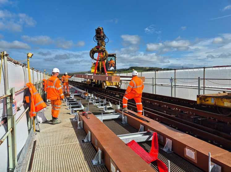
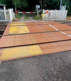
FFU:
for Eskmeals Viaduct A sustainable choice
Since 1980, Sekisui has engineered and manufactured synthetic wooden baulks made from Fibre-reinforced Foamed Urethane (FFU) and, in 2014, Network Rail engineers installed the first FFU baulks and crosssleepers as replacements for traditional hardwood on Military Canal & Blockhouse bridges in Kent (Rail Engineer 209, Aug/ Sept 2024). Since then, FFU has been used to provide track support on more than 70 railway bridges in the UK & Ireland.
FFU was first introduced on Japanese Railways in 1980 where early installations are still performing to specification. It is now widely used on railway infrastructure in 33 countries to support track on bridges, decking for level crossings, plain line sleepers, and Switch and Crossing (S&C) bearers.
An opportunity
In the Autumn of 2023, Sekisui was contacted by Jonny Rayson, Network Rail’s work delivery manager, Carlisle. Jonny told us that he had been to look at the FFU baulks which
had recently been installed at Bridge 140 Eskmeals Creep on the Cumbrian Coast Line. He was impressed, particularly by the regular geometry of the product when compared to hardwood and said that his team had experienced warping and twisting of timbers prior to installation on previous projects.
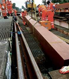
Jonny asked us to visit Carlisle Depot during December 2023 to present on the suitability of FFU for use on a significant project at Eskmeals Viaduct on the Cumbrian Coast Line. We were delighted to attend along with our UK fabrication partner
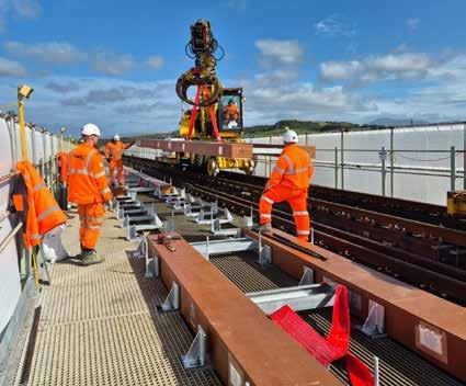
BSSL who prepared sample FFU joints, transoms, cleats, and holding down arrangements. Jonny and his team were impressed and FFU was incorporated into the design for this prestigious project which was to be delivered in a blockade from 6 to 23 September 2024. This was great news for Sekisui as the project required 137m³ of FFU to be produced at our Ritto factory in Japan. This twin track viaduct at 285 metres in length, provided not only the largest bridge project we have completed on Network Rail infrastructure, but also the largest Sekisui FFU global bridge project in 2024.
Project underway
In January, Network Rail’s designer HBPW confirmed the requirements. FFU production was completed in May and the FFU baulks were shipped
NIGEL KEIGHTLEY
to the UK for final fabrication into panels at BSSL’s facility in Middlesborough. These panels were then transported to Network Rail’s Doncaster Woodyard in August to be loaded onto engineering trains for transportation to site during the blockade.
Network Rail’s endorsement of FFU, citing reduced life cycle costs, extended longevity, and decreased maintenance requirements, aligns perfectly with the growing global emphasis on sustainable infrastructure solutions.
Jonny said: “The £4.5 million upgrade will make journeys more reliable for years to come and using synthetic materials instead of wood means there is an increased life expectancy, reduced maintenance costs for Network Rail, and reduced disruption for passengers and freight operators.”
Network Rail added: “The viaduct has stood for more than 150 years, and the improvements completed will
future proof the structure for generations to come. Climate change means that more intense storms, greater rain fall, and rising sea levels will put the viaduct under more pressure, so the work we're doing will stand it in good stead.”
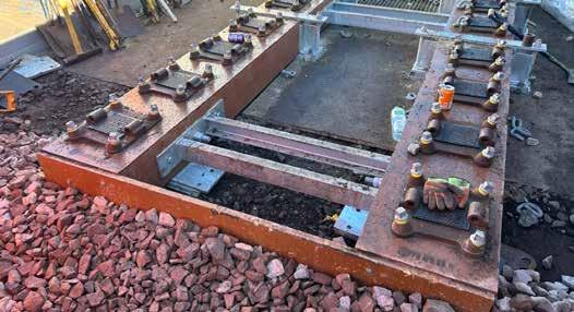
Achievements during the blockade included:
» 188 longitudinal FFU baulks installed in the place of timber waybeams.
» Replacement of approximately 600 transom bars over the structure.
» Removal of existing non-
compliant cleats and holding down arrangements and the installation of 1,060 new compliant cleats and HDAs.
» Removal and installation of over 1.1km of rails.
» Rail joints converted to Finlube and hardlock bolts from previous black oil.
» Over 43 tonnes of packing pieces installed to accommodate for the out of level steel works on the structure.
» Replacement of 80 defective softwood sleepers for new composite sleepers.
A great success
Jonny applauded the efforts of everyone on site: “The works were not without issues, however the way everyone responded and dealt with them, really proved that we could not have asked for a better group of people to complete this job.”
Sekisui was honoured to be invited to site on three occasions during the blockade, taking the opportunity to talk with staff on the projects about their experience. On completion of the work, we took time for discussion with Jonny and Chris Bibby, Network Rail’s regional track engineer Northwest & Central. They both reflected positively on the decision to use FFU.
The driver for change is to improve sustainability within track.
The FFU product will deliver a wide range of performance, value, and environmental benefits to the network, as well as helping us transition to a circular economy by keeping our materials in use for as long as possible.
“Following this success, the FFU product will be subsequently installed on more bridges on Network Rail’s Northwest & Central Routes,” said Chris.
Sekisui welcomes the opportunity to build on this accomplishment and greatly appreciates the opportunity to supply FFU for future projects. We would like to thank Jonny Rayson and the wider Network Rail team for choosing FFU, facilitating the site visits, and contributing to this article. Many thanks to Network Rail for giving us the opportunity to supply FFU for this project and to work with all the partners involved.
Special thanks go to Quattro Plant Ltd, Bottomley Site Services Ltd, Torrent Trackside Ltd, QED Scaffolding Ltd, HBPW & PBH, Vital Human Resources, Sekisui Chemical, all Network Rail team members, and everyone who contributed to the projects nominated charities: Eden Valley Hospice, and Jigsaw - Cumbria's Children's Hospice.
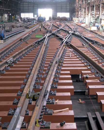
Background
Developed in conjunction with Japanese National Railways, FFU synthetic sleepers are made using a pultrusion process. Continuous glass fibres are soaked and mixed with polyurethane, and then hardened at a raised temperature, moulded, pulled and cut to length. This creates a high-quality material that has the life expectancy of plastic and the weight of natural wood, which can be worked like natural wood.
First installed in Japan in 1980, and adopted for standard sleepers and turnout sleepers, FFU has subsequently been installed on numerous projects in Europe over the past 20 years, particularly turnouts and bridges. Up to the end of 2023, there was more than 2100km of track with FFU sleepers around the world.
Tests of the original 1980 sleepers undertaken by the Railway Technical Research Institute in 2011 predicted that the FFU sleepers could safely continue in use for another 20 years, giving a total life of at least 50 years.
Synthetic Sleeper
Simply working & sustainable
Since 1985 we have installed more than 2,100 km of track
1.7 billion load tonnes | equivalent of 50 years use
Application: Ballast, Slab Track, Steel Construction and Direct Fastening
Can carry Axle loads of up to 65 tons
Use on High Speed Rail up to 300 km/h
Maintains long term track geometry
Contact with ballast similar to timber sleepers
Workable properties like timber sleepers
Testing on the hillside
The song ‘We’ll keep a welcome in the hillside’ comes to mind as I take a taxi up a Welsh valley to the miner’s welfare hall at Onllwyn, 15 miles northwest of Swansea.
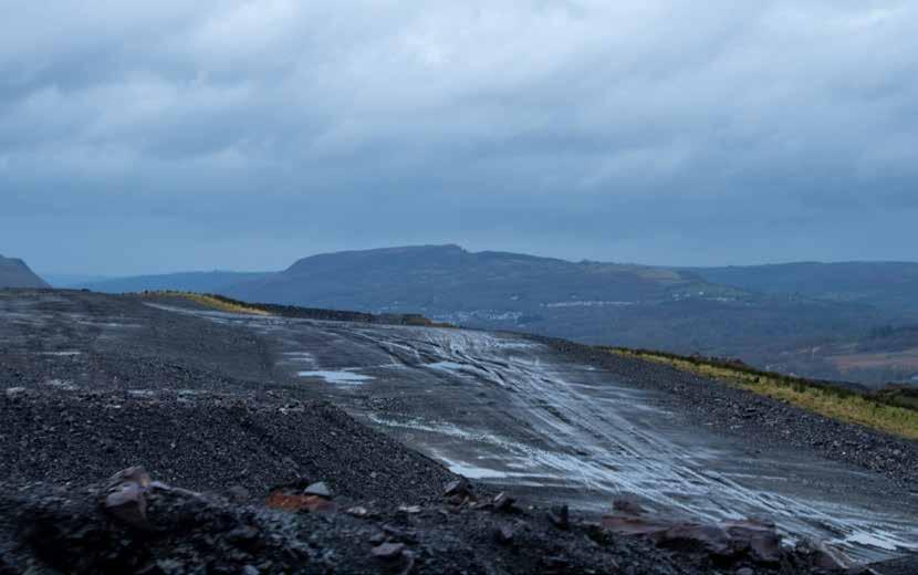
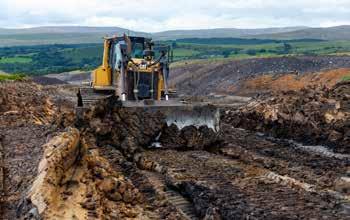
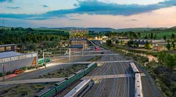
This is the base for my visit to the Global Centre of Rail Excellence (GCRE) which is constructing a major rolling stock and infrastructure test and innovation facility the size of Gatwick Airport on an opencast mining site on top of a Welsh hill at a projected cost of £400 million. At first, this seems to be an unlikely concept, yet it has the potential to provide an essential service to the rail industry while transforming an area which has not recovered from the loss of its mines.
The idea comes from the Welsh Government which, after engaging with the rail industry, saw an opportunity to both provide such test facilities and create prosperity in an area affected by decades of de-industrialisation. While developing this idea, the former Nant Helen opencast coal mine was identified as an ideal site. It is big enough for the required test loops, could be purchased at an affordable price and its remote location enables testing can be done around the clock. It is also railconnected and close to deep water ports.
Developing the site
The Welsh Government first announced its proposal for this test facility in 2018 when it appointed Arup to produce an outline design and an environmental statement. The 700-hectare site has been subject to extensive surface and subsurface coal mining activities over the past century. The site is not flat and will require cuttings and embankments necessitating more than one million cubic metres of earthworks which have been designed with an acceptable cut and fill balance.
The environmental statement, which was completed in 2020, considers environmental mitigation for visual impact from the adjacent national park; noise and traffic impact on adjacent settlements; topography and ground conditions; ecological sensitivities; and water resources and drainage. The site’s northern boundary is adjacent to the Brecon Beacons
National Park and there are several public rights of way across it, some of which will be extinguished with better connected routes created, with plans for 12km of cycle paths. GCRE was formally established in 2021 and obtained financial commitments of £50 million and £20 million from the Welsh and UK Governments respectively. A further £7.4 million of R&D funding is being provided from Innovate UK to promote construction innovation. The overall cost of the test facility is expected to be £400 million, hence GCRE requires private investment to supplement its kick-start funding.
Planning permission from local Councils, which allows 24 hour a day operation, was granted in 2021. The Welsh government purchased the site from Celtic Energy in October 2022. This consists of the Nant Helen hilltop, the summit of which is 335 metres above sea level, and on which the test
DAVID SHIRRES
Preparatory earthworks.
PHOTO: DAVID SHIRRES
PHOTO: GCRE
tracks will be built with sidings and support facilities about 100 metres below it, at the end of the branch line by the village of Onllwyn.
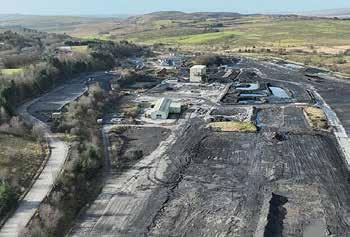
Work on the preparatory earthworks and clearance of the Onllwyn coal washery buildings started in 2022. However, the main earthworks and test loop construction await private sector funding.
Nant Helen
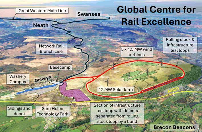
GCRE will be an independent railway controlled separately from the Network Rail branch line. As far as possible, people will be separated from its operation with automation of train operations. Initially, it was proposed that there would be a single-track 6.9km rolling stock test loop and a 4km infrastructure test loop, both with passive provision for double track. However, to reduce the significant costs of earthworks required for both test loops, it was decided that the infrastructure loop should be on the same formation as the rolling stock loop. Hence there are now to be two 6.9km
test loops – an outer one for rolling stock testing and an inner infrastructure test loop. These will be electrified at 25kV AC with passive provision for 3rd and 4th rail electrification.
The rolling stock testing loop will be constructed to Network Rail’s Cat 1A 200km/h TSI standard to European loading gauge. It will have 530- and 800-metre radius curves with two straights of 1,100 and 1,430 metres. Although built to 200km/h standards, its configuration will only allow 177km/h running. Signalling will be ETCS level 2 with the only conventional signalling being that required for connections to conventionally signalled lines. Both test loops will have full 5G and GSM-R coverage.
The infrastructure testing loop will be constructed to typical Network Rail 120 km/h standards to various track designs using recycled equipment where possible. The maximum speed on this loop would be 113 km/h. It will have conventional signalling with track circuits and axle counters with four-aspect signalling in both directions with an ETCS level 2 overlay.
It will have a section for testing novel infrastructure at which the two test loops will be separated by a bund to ensure that infrastructure testing presents no risk to the rolling stock testing loop. Apart from this section, both test loops will share the same 20-metre-wide formation.
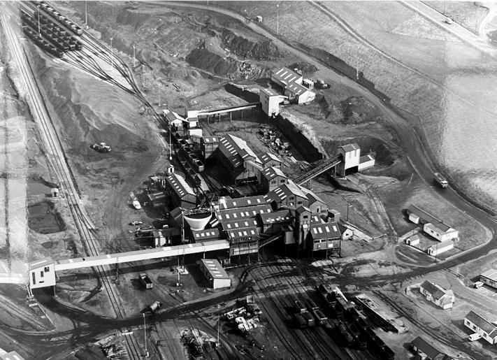
Onllwyn washery in 1994 and after GCRE site clearance.
PHOTO:
GCRE
PHOTO: GCRE
Onllwyn
The test loops are accessed by a line with a 1 in 37 gradient from the Onllwyn site which was originally the coal washery at the end of the Network Rail branch line. This site will become a multi-purpose GCRE hub with a wide range of facilities including approximately 4km of track, sidings where rolling stock can await, begin, and end its turn on the testing loops, further storage sidings, and washing and fuelling roads including future provision for hydrogen trains and other alternative fuels as well as a four-road rolling stock maintenance shed. Although it is anticipated that most rolling stock will come to GCRE by rail, the centre will be able to accept trains delivered by road.
Basecamp will extend to the village of Onllwyn and will be GCRE’s shopfront. It will support the many different users of the GCRE who will spend extended periods of time at the site.
The Washery Campus at Onllwyn will also include a multistorey control building from where testing activities will be managed, a multi storey staff block with overnight stay facilities, conference facilities, and a research and development centre. GCRE is collaborating with the University of Birmingham’s Centre for Railway Research and Education (BCRRE) which is working with Welsh Universities to develop this R&D centre. It is intended that the Sarn Helen Technology Park will be developed over time to the west of the Washery Campus to become a world class research and development centre.
A sustainable net zero railway
GCRE intends to become Britain’s first net-zero carbon operational railway with an estimated power consumption of up to 30MW. This will be powered by a 12MW on-site solar farm and a direct connection to a local 20MW wind farm. Its 25kV AC overhead line electrification will be fed by a static frequency converter.
(Below) Washery sidings illustration.
(Below) Basecamp illustration.
(Below) Sarn Helen Technology Park illustration.
PHOTO: GCRE
PHOTO: GCRE
PHOTO: GCRE
The facility will offer future opportunities for large scale renewable energy generation and storage with space for solar farms of up to 32GW, five wind turbines up to 75GW, and battery storage of up to 1.725 MWh. This offers various research opportunities, for example on the novel use of energy storage in railway environments. There will also be provision for storage and development use of hydrogen, bio methane, and other net zero fuels.
GCRE will also embed low carbon and sustainable or recycled materials in its construction. For example, two miles of rail track replaced by Network Rail as part of the Severn Tunnel track renewals will be reused at the GCRE facility.
Rolling stock testing
The electrified high-speed test loop offers efficient first-in-class testing, fault free running, modifications, and upgrade testing, with on-site engineering and innovation facilities. GCRE’s branch line access to South Wales Main Line provides easy access for UK stock for which it can be difficult to find train paths for mileage proving runs. European stock can be transported to GCRE using nearby deepwater ports.
It will be possible to use both test loops to run in a ‘figure of eight’ to create dynamic changeovers between ETCS level 2 signalling / ATO and conventional signalling with track circuits, axle counters, AWS, and TPWS. Such rail system integration testing could be particularly useful with the implementation of ETCS programme.
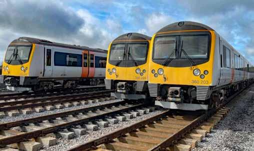
GCRE can also test rolling stock systems such as suspension, ETCS, and novel train control. To do so, in 2022 it acquired a fleet of three 2004-built Class 360/2 EMUs which previously operated Heathrow services and became surplus to requirements when the Elizabeth line opened.
The rolling stock test loop will also have a representative station platform and virtual stopping points. It will be possible to incorporate defects for train certification. Furthermore, GCRE also provides the opportunity to facilitate the approval of new rolling stock by providing an offline live railway environment to demonstrate new stock to approval bodies.
Class 360/2 units at the GCRE site.
PHOTO: GCRE
Infrastructure testing
To test infrastructure, the intention is to run heavily loaded, unmanned GCRE Class 360/2 units and other trains yet to be acquired. They will run for 16 hours per day under Automatic Train Operation (ATO) or will possibly be remotely controlled. These trains will run five days a week in a 10-week cycle followed by a two-week downtime to set up and remove experiments. In this way, every three months the loop’s infrastructure will be loaded with five million gross tonnes, giving 20 million gross tonnes annually, with over 60,000 axle passes. While this is being done GCRE will offer a full digital on-track testing analysis.
The infrastructure test loop will be able to incorporate all types of new infrastructure. It will have a replaceable bridge deck, a section for testing switches and crossings, and one for testing novel OLE. In addition, it will offer accelerated endurance testing of long-life railway assets to give an understanding of how such assets will perform in the future.
As an example, the test loop could include a section of recycled rail, sleepers, and ballast from HS1. Subjecting this to endurance testing would enable HS1 to understand degradation and failure mechanisms before they occur on the real railway to develop a future proofed asset management plan.
Innovation in construction
As well as supporting innovation though its testing facilities, Innovate UK recognised that constructing the GCRE facility provides an opportunity to support construction innovation for which it has provided R&D funding of £7.4 million. This money has been awarded to winners of an innovation competition in which entrants must demonstrate how their innovations will reduce whole life costs, reduce timescales, or result in more efficient materials handling or efficient use of resources.
09F
words
The competition has two phases. The 24 winners of the first stage, announced in January 2023, were each awarded a grant of £25,000 to produce a feasibility study for railway construction innovation while constructing the GCRE facility. This had to address one of nine
[COMPETITION WINNERS TABLE]
GCRE phase 2 innovation in construction winners
Associated Utility Supplies A composite twin track cantilever for smarter rail electrification
Drone Evolution Use of tethered drones in rail
Enerail Energy control system for energy storage and renewables
Furrer + Frey GB Innovative cantilever for greener electrification
Furrer + Frey GB Cost-reducing dynamic electrification gradient system
Hypertunnel Tunnelling innovation
Ingram Networks Delivering telecommunications innovations in railway construction
Mimicrete Mimicrete vascular self-healing solution in railway practice
Nationwide Engineering Research & Development Graphene enhanced concrete sleeper for lower embodied carbon
Robok Intelligent real-time, monitoring & detection video analytics for rail construction
Silicon Microgravity Gravity sensing for rail construction
Thomson Engineering Design Mobile rail panel handler
Universal Signalling Universal interlocking: next generation digital signalling as overlay
themes: trackwork; OLE; earthworks and structures; power supply infrastructure; telecommunications; perimeter and cyber security; monitoring and maintenance; railway operation and automated systems; or ecology and habitat creation.
These winners were then invited to enter the phase 2 competition for funds to develop and demonstrate their innovation during GCRE’s construction phase. In January 2024, the 14 companies who had won the phase 2 competition were announced. In total they had been awarded innovation funding of £5.9 million, as shown in the table (bottom left).
GCRE’s future
GCRE is an ambitious project for which there is a great deal of support. It has signed agreements for use of its facilities with a range of companies. These include Network Rail, CAF, Xrail, Frauscher, Ricardo, Thales, and Hitachi. Additionally, over 200 UK and European companies have signed a letter of endorsement stating that a purpose-built site for research, testing, and innovation of rolling stock, infrastructure, and cutting-edge new technologies is urgently needed to tackle the challenges faced by the industry.
Moreover, the annual global rolling stock market is growing at 3% per annum and estimated to be worth over £50 billion by 2030. Hence there will be a significant demand for new rail test tracks, especially as few current facilities have long loops for high-speed running. There is also pent-up demand for infrastructure testing as there is no significant European facility for accelerated rail infrastructure testing.
£533,189
£320,433
£505,669
£163,026
£415,178
£450,347
£557,406
£566,600
£568,102
£340,436
£411,000
£156,111
£305,530
£559,070
Hence it is clear that GCRE has many potential customers and so would seem to be a worthwhile investment. Yet raising the required £300 million investment is a significant challenge. GCRE CEO Simon Jones recently stated that he hoped to get this funding over the line later this year. If so, the major earthworks, which cannot be done during the winter, could start in April 2025. Moving more than one million cubic metres of material to create a 6.9km loop with 20-metre-wide track bed formation would then take until September 2025. After the installation of track systems, it is expected that GCRE would start to operate its first test trains in 2027. However, if finance cannot be raised in time it will then not be possible to start the major earthworks until April 2026.
The vision is that GCRE will become a leading hub of research and innovation that provides customer-specific engineering and operational test programmes. This could also provide a representative, offline, ‘live’ railway environment for companies to demonstrate new products in a much more accessible way than is currently the case. In this way it is intended that GCRE will eventually host the railway equivalent of the large Motor Industry Research Association (MIRA) technology park at its automotive proving ground near Nuneaton.
GCRE also aims to re-build local prosperity through social benefits for neighbouring communities which have not recovered from the area’s de-industrialisation. It is intended that 1,100 new jobs will be created over the next decade. It has been estimated that every £1 spent on the GCRE facility will deliver £15 of wider benefits.
At this challenging economic time, it is to be hoped that funding can be secured for this worthwhile investment.
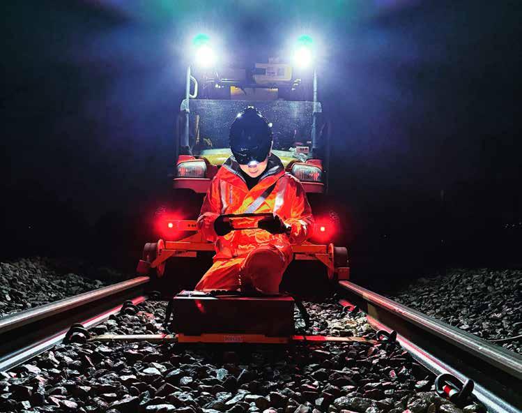
Remote monitoring INNOVATION TO BOOST WINTER RESILIENCE
Rail engineers face considerable pressure to maintain high levels of asset resilience in the face of a warmer, wetter climate placing unexpected pressures on ageing and over-stretched infrastructure. While the desire to upgrade or replace assets may be strong, the capacity to do so cannot possibly meet the demand, so alternative ways must be found to keep trains running safely and cost-effectively.
Access to reliable, continuous data from automated condition monitoring systems can play a vital role in this battle.
Engineers at remote condition monitoring developer Senceive have been busy adapting their well-established wireless monitoring solutions to address two of the most critical challenges affecting the stability of railway earthworks slopes:
1. The early detection of landslips and other shallow failures such as washouts and drainage failures
2. Monitoring to detect rockfall events
Landslip detection
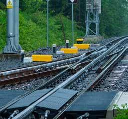
There is a clear relationship between the increasing frequency of extreme rainfall events and the number of slope failures affecting railway earthworks. Network Rail geotechnical engineers have relied on wireless remote monitoring solutions to provide early warning of landslips since 2019 and have now deployed more than 40,000 Senceive tilt sensors covering around 50km of the UK network. Utilising the company’s intelligent InfraGuard™ monitoring software, the technology has come a long way in that time.
One example of this continuous improvement is the transformative improvement made to the system’s cameras, which are triggered automatically by ground movement to provide high resolution images day and night – without needing a flash or illumination source. Using cameras capable of detecting a football-sized object at a distance of 50 metres in any light conditions, this supports quick decision making and can dramatically reduce the risk of disruption and derailments.
Another example is the slicker integration with geotechnical monitoring instruments, such as piezometers and inclinometers, meaning that the automated wireless system can now monitor both shallow and deep ground movement.
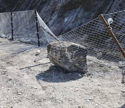
Rockfall monitoring
While wireless remote monitoring technology has been widely adopted to detect large mass failure of soil slopes, the established methodology was inappropriate for rock slopes, which are often characterised by movement of individual boulders or localised debris. Because these smaller objects can fall between tilt sensor locations – yet still pose a significant threat to rail and other infrastructure – a bespoke solution was required.
As the world’s biggest user of wireless slope monitoring, Network Rail expressed interest in adapting the existing wireless technology. In early 2024 it commissioned trials on rocky slopes at a test site in Switzerland, which supported the development of an innovative multi-mode wireless detection system.
In summary, this solution is built around monitoring the effects of rockfall debris hitting catchfences, and it can be triggered in any of three ways to provide a robust, reliable solution with a high detection rate and a low incidence of false alarms. In all three modes the unique intelligence built into the sensors can trigger the InfraGuard software to escalate an alert to users, accelerate reporting of neighbouring sensors, and transmit photos of the site.
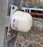
» Mode 1: rock hits fence causing rotation of fence postsdetected by tilt sensors mounted on the posts.
» Mode 2: rock hits fence, but the force is absorbed by the wire and the posts do not move – the movement is detected by draw wire sensors
» Mode 3: rock bounces down the slope, hitting fence and bouncing over it - the sudden acceleration is detected by the impact sensors in the Senceive NanoMacro™ tilt nodes mounted on posts, regardless of their pre-set sampling frequency.
Innovation is crucial
Wireless innovation is crucial to improved climate resilience. With winter on the horizon in the northern hemisphere, the advantages of wireless solutions are significant. The ability to keep constant watch on vulnerable assets reduces the risk of trains hitting blockages on the line, and the automation of this process cuts the need for a lot of muddy, time-consuming, and costly site visits. The use of tilt sensors for track and earthworks monitoring does not rely on line-of-sight, so is unaffected by snow cover and short hours of daylight.
It is clear that wireless monitoring technology has come a long way in the last two decades, and that constant development and improvement of new applications is helping engineers to address the challenges posed by changing weather conditions.
Rail operators often find that they have need for temporary staff, especially at times of great change. Since the award of its contract in 2017, Southwestern Railway (SWR) has ordered new Alstom (née Bombardier) Arterio Class 701 trains and had proposed that they, together with the refurbished Class 442 and the existing Class 444 and 450 fleet, would lead to the withdrawal of the Class 455, 458, and 707 fleets.
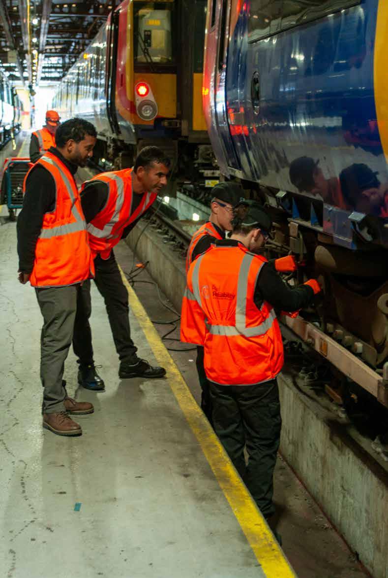
This preamble leads to a focus on the Class 458 fleet and its support. The country had been in lockdown due to Covid since March 2020 and all industries were in a state of turmoil due to material supply and staffing levels. In December 2020, Rail Reliability Consultancy Services (Rail Reliability) engaged with SWR to provide it with technical labour and technical support to help with the problems the company was encountering with the maintenance activities on the Class 458 fleets. Using Rail Reliability for this work allowed SWR to release their own team members to be trained on Class 701.
At the time of engagement, SWR only had 50% of its 36-strong fleet available for service with reliability of the remaining units being unpredictable. Initially a team of six was provided to improve availability of the fleet until, under the original plan, it was withdrawn and handed back to Porterbrook. It was then decided to keep 28 of the 36 five-car Class 458 trains which are now being reconfigured by Alstom into four-car sets and regeared to their original 100mph maximum speed. Originally these were to operate the London-
Portsmouth Harbour service but are currently being used on outer suburban networks.
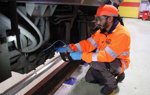
With the change of plan, Rail Reliability now supplies a managed service with 21 team members. This includes project management and technical support together with senior technicians and exam technicians. Within the team of senior technicians, Rail Reliability has specialised track call fitters who are trained and accredited to work trackside. When requested by SWR, they respond to track calls or provide outstation support during exceptionally hectic times and/ or occasions such as the King’s Coronation Concert at Windsor and Twickenham Rugby.
Now in its fourth year, availability and reliability has grown without there being any long term stopped units. This allows SWR to operate a smaller, reliable fleet while other units are withdrawn for refurbishment and hand back to Porterbrook.
Rail Reliability’s role
Rail Reliability now carries out all routine and corrective maintenance on the Class 458 units, including fault finding, defect rectification, and modification works on all systems, including air conditioning, Wi-Fi, CCTV, heating, brakes, doors, traction, auxiliary systems, and on-train monitoring systems.
Rail Reliability is also carrying out dilapidation repairs of the surplus units ready for their handback to Porterbrook.
“RRCS have worked with us for several years now to provide a competent and reliable team to support our fleet maintenance activities during a period of change within the business and the wider railway industry. A truly collaborative relationship at all levels that has resulted in the desired stability and reliability of the fleets they have been engaged with.”
Neil Drury, engineering director, SWR
MALCOLM DOBELL
Working closely with SWR’s engineering, technical and production teams, Rail Reliability regularly creates, assists with, recommends, and executes the following:
» Fleet checks.
» In process checks.
» Major fleet wide fault investigations and rectification.
» Fleet performance reviews.
» Fleet modifications.
» Technical queries.
» Updates to vehicle maintenance instruction.
In addition, Rail Reliability collaborates closely with all stakeholders including Alstom and Porterbrook to address long-term problems, obsolescence, and the implementation of first-in-class modifications, such as the monitoring of cab doors open and close signals in the On Train Monitoring Recorder. Rail Reliability has made significant progress resolving faults in the passenger Wi-Fi and CCTV networks, by identifying and rectifying wiring and data backbone issues.
To achieve all this, Rail Reliability tracks Class 458 material on a unit-by-unit basis and works closely with SWR’s materials team. This tracking information is used to plan material requirements based on likely consumption to ensure that spares stock is maintained at an appropriate level.
Lessons learnt
The description above is of an organisation trusted by SWR to look after the fleet. But, as Rail Reliability’s Richard Gasper told Rail Engineer: “When taking on the Class 458 maintenance contract over three years ago, Rail Reliability was mobilised to support SWR managing the process of restoring the fleet to the condition required for hand back to Porterbrook”.
This soon changed, but, he added: “As the original plan was to hand the fleet back, material suppliers started winding down their supply for this fleet and a lot of material became obsolete.”
Richard added that a great deal of work was required to address obsolescence issues after SWR decided to keep the fleet. Even though the material supply has improved there are still issues to resolve.
Managing spares shortages
Rail Reliability uses its specialist knowledge of the fleet to keep the trains in service while significant parts are sourced. This requires flexibility to ‘borrow’ parts where possible from a unit that has been stood down. For example, if a traction component is defective on a driving motor coach this would also lock out the auxiliary converter causing a loss of some passenger facilities such as lighting and air conditioning. A unit in this condition cannot enter service from the depot until rectified.
With no material in stock, removing a part from a stopped unit risks creating a so-called 'Christmas tree'. Rail Reliability realised that the required component could be removed from the nondriving motor coach which has no auxiliary converter. This meant that both auxiliary converters would operate supplying all auxiliary and passenger comfort systems. While one coach set of motors would not operate, the unit could operate in service whilst coupled to another as a 10-car set.
Maintenance planning
Once Rail Reliability was able to supply the number of units to meet the required service availability, the team noticed that many Class 458 units would become due for examination at approximately the same time. This put maintenance staff under
pressure where exams were completed but historic defects were not closed, and passenger interface defects might not be attended to. The knock-on effect of this could be temporary availability but poor reliability.
Rail Reliability’s project manager reviewed fleet miles, unit by unit, and requested that train formations were changed to allow unit mileage and exams to be managed more appropriately. When availability was high, Rail Reliability would request that units with the lowest mileage be held to enable the spread of the exam load. This approach created a steadier beat rate for units falling due for exam, relieving pressure on maintenance teams and allowing for historical and passenger interface defects to be addressed.
The team
For Rail Reliability to be successful it was important to hand pick staff to suit the requirements of the contract. All employees are extremely knowledgeable, competent, driven, and highly skilled within their roles. The team has wide experience, some with rolling stock from their time spent serving as railway apprentices for some of the major OEMs and TOCs, while other team members are apprentice trained and have experience in other engineering fields.
Shaun Lacriarde says: “We work hard to maintain and improve competence from our team from their initial interview and throughout their working career. This includes regular performance reviews which are used to determine any training needs and to provide an opportunity to voice concerns about any concerns they may have.”
He adds: “Our managers ensure that all aspects of our integrated management system is complied with. Local HSQE arrangements are routinely monitored by our HSQE department which maintains close communication with the SWR HSQE team.”
SWR has delegated authority to Rail Reliability’s senior technicians to initiate new work orders, update existing ones, and follow them through to completion on SWR's asset management system. The technicians provide comprehensive reports which are used on fleetwide asset management matters as well as attribution when dealing with technical incidents on the railway.
Richard and Shaun would like to thank SWR for its continual trust and support over the last four years, and for allowing them to collaborate so closely. The Rail Reliability team has worked alongside all departments at all levels to gain this working relationship and appreciates the opportunity it has been given to present its professionalism.
ENHANCING SECURITY AND A SAFER WORKING ENVIRONMENT Traka:
Mike Hills, Traka’s UK development manager, highlights how advanced key and asset management solutions contribute to enhanced security, health, and environmental sustainability.
In today’s fast-paced and highly-regulated rail sector, with increased pressures for operational efficiency from discerning passengers, ensuring safety, wellbeing, and the environmental health of staff and users is paramount.
The rail sector faces evolving security challenges demanding immediate attention and innovative solutions. With increasing threats to infrastructure, including potential cyberattacks, terrorist, and physical breaches, ensuring robust security measures is critical.
Aging infrastructure and the need for modernisation add complexity to maintaining secure operations. The management of access to sensitive areas and assets remains a significant concern, as unauthorised access can jeopardise both safety and efficiency.
Addressing these security issues requires a comprehensive approach, integrating advanced technology and strategic management practices to safeguard rail networks against current and emerging threats, while ensuring operational continuity and safety.
Advanced key and asset management systems play a crucial role by securing access to critical areas and preventing unauthorised entry, reducing safety risks. Efficient management of assets, such as communication tools and equipment, enhances operational reliability and minimises downtime, contributing to staff wellbeing.
Integrating sustainable practices – such as optimising resource usage and reducing waste – also supports environmental health. By adopting these measures, rail operators can improve safety, operational efficiency, and sustainability, aligning with industry standards and creating a safer, futureproof rail network.
Prioritising safety
Safety in the transport sector involves not only the secure management of keys and assets but also ensuring systems are in place to make assets readily available for users to keep operations smooth and information flowing.
Traka’s key and asset management solutions can play a crucial role in enhancing safety across rail, airports, marine, and other transport sectors.
» Secure access to critical areas. Traka’s intelligent electronic key management systems ensure only authorised
personnel have access to critical areas and equipment. By using advanced technologies such as RFID and biometric access, systems prevent unauthorised access and reduce the risk of security breaches. This is particularly important in high-stakes environments like rail networks and stations, where security breaches can have serious consequences.
» Live tracking and real-time monitoring. Traka solutions provide live tracking of keys and assets, ensuring critical resources are always accounted for and accessible only to those with the appropriate clearance. This real-time monitoring helps prevent the loss or misuse of important equipment, enhancing overall operational safety.
» Detailed audit trails. Traka’s systems offer detailed audit trails, which are essential for maintaining security and accountability. These audit trails help organisations track who accessed which keys or assets, when, and for what purpose. This information is crucial for investigating incidents, adding accountability and ensuring compliance with safety regulations.
Promoting wellbeing
Wellbeing in the transport sector extends beyond physical safety to include the health and efficiency of personnel, both mentally and physically. Effective asset management solutions can contribute to a safer and more productive working environment.
By automating key and asset management, Traka’s solutions streamline operational processes, reducing the time and effort required to manage critical resources. This efficiency allows staff to focus on their core responsibilities, reducing stress and improving job satisfaction.
» Enhanced reliability. Traka systems ensure essential equipment such as personal digital assistants (PDAs), radios, and laptops are always available and functioning correctly. This reliability is crucial for maintaining smooth operations and preventing disruptions that can impact both staff wellbeing and service delivery.
» Minimising human error. Traka’s advanced management solutions reduce the risk of human error by providing automated tracking and reporting. This reduces the chances of mistakes that could lead to safety incidents, contributing to a safer and more controlled working environment.
A commitment to sustainable practices
Environmental health is increasingly becoming a priority in the transport sector, with a growing emphasis on sustainability and reducing the environmental impact of operations. Traka is committed to supporting these efforts through our technology and solutions.
» Efficient resource utilisation. Traka’s asset management systems optimise use of resources, reducing waste and ensuring equipment is used efficiently. The addition of fault logging enables users to record and return faulty devices instantly, which cannot be used until issues are resolved. This contributes to more sustainable operations by minimising the need for redundant equipment and reducing overall consumption.
» Green technologies. As the transport sector moves towards greener technologies, such as electric or hydrogen-powered trains, Traka’s solutions can support these initiatives by providing secure management and tracking of new technologies and equipment. This ensures environmentally friendly practices are supported by robust management systems.
Reducing environmental impact
Traka systems help organisations track and manage resources in a way that supports environmental health. By ensuring that equipment is maintained and used efficiently, we contribute to reducing the environmental footprint of transport operations. In summary, addressing the challenges of security, efficiency and sustainability is crucial for modernising operations and ensuring long-term viability. The integration of advanced key and asset management solutions represents a significant step towards enhancing safety, wellbeing, and environmental health. As rail operators face evolving security threats — from cyberattacks to physical breaches — implementing robust management systems is vital. These systems not only secure access to sensitive areas but also provide real-time monitoring and detailed audit trails, which are essential for maintaining operational integrity and regulatory compliance.
Effective asset management contributes directly to staff wellbeing by streamlining processes and reducing downtime. Automated systems minimise the risk of human error, ensuring essential equipment remains operational and available, supporting a more efficient and less stressful working environment.
Environmental sustainability is achieved by optimising resource usage and supporting green technologies – rail operators can significantly reduce their environmental impact.
Traka’s solutions facilitate this by ensuring efficient management of equipment and resources, which aligns with broader industry goals for sustainability.
Prioritising these aspects through advanced technology and strategic practices will not only enhance safety and operational efficiency but also create a more resilient rail network, benefiting both the industry and the communities it serves.
For more information, visit Traka’s dedicated Transportation page, by scanning the QR code:
DAVID FENNER
ECDP: AN UPDATE
Network Rail recently gave a press briefing in York to provide an update on progress with the East Coast Digital Programme (ECDP) and to outline how this supports the rollout of ETCS across parts of the network during Control Periods 7 and 8, laying the foundations for the longer-term signalling strategy.
The presentation started with Toufic Machnouk, director, Network Rail Industry Partnership Digital, outlining the fundamental reasons that require the railway to move to in-cab signalling based on ETCS. The fundamental point is that traditional signalling is infrastructure heavy, especially in terms of the lights on sticks scattered across the network, as well as the other supporting equipment including control equipment and cables, repeater signals, advance junction indicators, the control logic within the interlocking systems that make sure only safe indications are given, and so on.
This equipment is capital intensive and, because much of it is distributed across the network, it has a high maintenance cost that ends up being reflected in operational and maintenance charges. Add to this
the compromises necessary because signal spacing must accommodate trains with different performance characteristics, and the human factors risks of the driver reading the wrong lineside signal or misunderstanding the significance of that particular signal, and you get an underperforming railway.
In-cab signalling provides a means to both reduce cost and increase performance, and it provides comprehensive Automatic Train Protection (ATP). To emphasis these points, the target is a 42% reduction in signalling unit costs helped by a 46% reduction in track access requirement for digital signalling with a 33% uplift in railway system capability. Finally, the move to digital signalling has a sustainability advantage by reducing embedded carbon by 39%.
Scope of the challenge
The major challenge is not really the technology but the scale of the change process it brings. To move to in-cab signalling requires every train operating on the relevant section of line to be fitted with the necessary onboard equipment. On the national network that can be a significant portion of some fleets, especially, but not exclusively, freight. Once fitted, the drivers need to be trained as well as their supervisors and others in the train operating community. Additionally, without lights at the end of the platform there will potentially be changes to train despatch arrangements at some major stations, further increasing the scope of change.
The move to in-cab signalling also impacts on the rules for how the railway is designed and operated, so the training needs to address those rule changes as well as the functioning of the new kit. Then there are the changes in terms of design, operation, and maintenance affecting many aspects of railway operation.
This is all without mentioning the equipment suppliers and other contractors involved in building, fitting, and maintaining the railway. At present, changes to systems are managed through the Network Code but this was not really established to cope with this scale of change. It is therefore essential that the whole industry works in partnership to manage and coordinate the change. The industry partnership digital programme, with a whole industry partnership board overseeing the plan, is essential. This is particularly necessary because of the way the railway industry in the UK is currently organised with different units having different short-term targets. The whole industry change required needs a strategic whole industry approach to the project.
Five-stage plan
The digital signalling masterplan is a five-stage plan to move to a situation where in-cab signalling is the norm. It started with the Cambrian pilot project back around 2010 which fundamentally demonstrated the system was technically able to perform the task of safely controlling train movements. This was augmented by the Thameslink core project and fitment of ETCS for the Heathrow spur and Paddington to Heathrow route.
The next stage is the pathfinder project on the Northern City Line. Here the primary objectives are not to technically prove the system but to demonstrate that processes for implementation can be developed which show such projects can be delivered to meet the business need. Currently, the pathfinder project on the Northern City Line to Moorgate is using ETCS on more than 60% of the train movements although lineside
signals are still present until all drivers on the route are trained in the use of the system. The lineside signals will then be isolated, which is expected to happen around springtime 2025, and later removed.
The pathfinder project has involved nine project implementation topics of which five have worked well but four, namely system proving, system approvals, train upgrade processes, and driver training can be said to have been “lived through” and require more work to streamline them. Step three of the masterplan is the pioneer phase which is now developing between Welwyn and Hitchin and will later progress north along the East Coast Mainline between now and 2028.
The Welwyn to Hitchin section has now been converted to operate in both conventional signalling mode and as an ETCS mainline railway. Indeed, at the end of June, the first test train was run through the section under ETCS control. Once the vehicles have been fitted and the staff trained this section will operate under ETCS control
but with lineside signals retained to enable training to continue. This will be followed by resignalling with ETCS sections from Hitchin to Fletton just south of Peterborough without lineside signals, and from Fletton to Stoke tunnel south of Grantham retaining lineside signals because of the additional vehicle types joining this route at Peterborough.
Stage four of the masterplan, the portfolio stage, has now begun and looks to build the whole industry’s capability to run multiple projects simultaneously. This is just starting, but there is an expectation that ETCS will form the backbone of the signalling systems, not just on the ECML but also the Transpennine Route Upgrade and in future the resignalling of the northern end of the English portion of the WCML from Warrington to Carlisle. From a signalling renewal perspective, it is also likely to include resignalling of the Brighton and Midland mainlines partly driven by the shared vehicle types using these routes and the ECML. Finally, stage five, expected to start around 2029, is when resignalling projects will begin to consider ETCS rollout as the normal form of resignalling.
Pioneer phase
Ed Akers, Network Rail’s industry partnership director, provided greater detail of the scope and scale of the ECML’s pioneer phase. Six different onboard systems – two from Alstom, two from Hitachi, one from Siemens, and one from CAF – will be fitted across 40 different vehicle classes involving a total of over 700 vehicles. Then, there
Engineers work on ECDP between Welwyn and Hitchin.
Engineers work on ECDP between Welwyn and Hitchin.
PHOTO: NETWORK RAIL
PHOTO: NETWORK RAIL
are more than 3,000 drivers to be trained to drive using cab signalling, plus around another 7,000 who will not drive along ETCS fitted routes but need to be familiar with the new equipment in the cab and its operation in Level NTC, i.e. how it functions when running in areas of conventional signalling. Finally, more than 30 organisations involved in or working to deliver the ECDP.
On the Northern City Line between Finsbury Park and Moorgate the first passenger service ran in November 2023 with over 60% of services now signalled under ETCS control as drivers complete training. So far it is reported that driver acceptance is going well. It is hoped that all drivers on this section will be trained by early 2025 and thus all movements will be under ETCS control.
The section from Welwyn to Hitchin was commissioned in February 2024 and now provides both lineside signals and an ETCS capability. This will be an important test site to demonstrate improved capability because of the two-track section between Digswell Junction and Woolmer Green. The first train to be signalled over this section using ETCS was a Class 717 emu on the 2 June 2024. Ongoing, mainly overnight testing is being performed to fully understand the interactions between the train, the Radio Block Centre (RBC) and the trackside. This phase is being led by Siemens Mobility as the train control partner, albeit with involvement of many other members of the partnership.
The future roadmap for the ECDP envisages testing, approvals and assurance work continuing through the rest of 2024 and much of 2025.
The Northern City Line to Moorgate should achieve no signals operation in spring next year followed toward the end of 2025 by the start of regular ETCS operation of some trains over the Welwyn Hitchin section. The volume of trains operating will gradually increase as the number of trains fitted and drivers trained grows, with full ETCS service anticipated to occur in 2027. That year is also expected to see the first section of ETCS being prepared for operation without lineside signals. There is still discussion as to whether this will be Biggleswade to Fletton or the Hertford Loop although the primary aim is the former.
Finally, it is planned that full ETCS operation from Kings Cross and Moorgate to Stoke tunnel will be operational in early 2030 with signals only remaining from Peterborough to Stoke tunnel because of the additional traffic joining the route at Peterborough.
AtkinsRéalis has partnered with a test laboratory at Egham which is being used to provide additional and independent test resources supplementing those of Siemens at Chippenham. These are being used to test several systems but especially to check fleet fitment plans and ensure compatibility with the proposed trackside configuration. Dynamic testing is then taking place at the Rail Innovation and Development Centre (RIDC) at Melton where a portion of line has been equipped to facilitate such tests.
Train fitment
Train fitment is one of the major challenges, especially for freight. The Class 66 is a common sight across the network but despite their similar external appearance there are many subtle variations across the set of Class 66 locomotives. A common base design has been agreed among the operators. This needed a significant level of cooperation between all parties. The First in Class (FiC) 66 is now at Melton RIDC and about to complete dynamic testing.
Another Freightliner Class 66 is about to undergo FiC fitment using a fitment model where the Freight Operating Company (FOC) delivers
PHOTO: GOVIA
the fitment programme itself on its own asset. Ideally this is the preferred fitment model as the vehicle owner can then manage fitment in the wider context of vehicle utilisation. A Class 67 locomotive is also progressing through FiC and will in due course visit Melton RIDC. In terms of electric freight locomotives, an FiC design for the Class 88 is complete and ready for fitment.
Fleet fitment for passenger service on the ECDP route is perhaps a little easier as a significant portion of the rolling stock is either fitted or has provision for ETCS. In particular, the Class 717 units providing the suburban service are already fitted for ETCS operation.
The Class 700s which provide the wider Thameslink services are fitted with ETCS although this needs to be upgraded to comply with the standards applicable to the ECDP roll out. A contract is in place for this work to be done. The other major outer urban stock in use is the Class 387 unit. The FiC is underway on 387 101 and, given the scale of the Electrostar fleet across the south eastern network, this is seen as strategically important.
One class of Intercity train is being retrofitted, namely the Class 180, while the Class 800 and other 80x units are having their pre-fitted ETCS system upgraded. The FiC for the Class 800 is currently underway with dynamic testing expected to commence at Melton RIDC in September while the Class 180 design is approaching the approval in principle stage having previously been fitted with ETCS during heavy maintenance. It is notable that the Class 91 locomotives are not part of the plan due to their scheduled replacement by new trains.
Fleet fitment does not finish there. The ECML is significant in charter train operation and of course needs regular track maintenance. In consequence there are plans to fit some heritage vehicles for charter operation, as well as a range of on-track machines and monitoring
trains. In particular, the steam locomotive Tornado is currently undergoing static ETCS testing while one of the Class 55 Deltic locomotives is currently being fitted. The fitment of Tornado is seen as something of a pioneer experience, being, to the best of our knowledge, the first steam locomotive in the world to be fitted with ETCS. Class 43 HST power cars are also being fitted to support high speed track recording.
There are also new train classes to be considered and further developments to the ETCS specification especially in terms of methods and accuracy of train positioning. It is also true that the scope of the migration will be subject to changes in priority as a result of business justification and funding.
Overall, Network Rail provided a good presentation highlighting some of the challenges of making major changes on a diversified railway and exposed some of the reasons for the extended timeframes of the programme.
As a footnote to the presentation, on the 22 August Network Rail announced that the First in Class 66 freight locomotive 66 039 had completed trials at the Melton RIDC, demonstrating transition in to and out of ETCS level 2 and various other tests to confirm operation in degraded modes. The
Summing up
During the Q&A session that followed the initial presentation it became clear that the project is not running in isolation and ongoing changes to the technical environment are expected during its life cycle. In particular, there were questions about updates to the track-to-train communication system initially to enable ETCS to use packet switched messages as well as, early in the 2030s, the move from GSM-R to Future Railway Mobile Communication System (FRMCS) which will become essential as ongoing support for GSM declines.
locomotive was fitted with Siemens’ Trainguard 200 onboard system and will now do mileage accumulation runs prior to the start of fitment to other class 66 locomotives.
It was also confirmed that 387 101 had similarly completed its First in Class tests at Melton RIDC fitted with Alstom hardware and likewise will do mileage accumulation prior to fitment at Hornsey depot of the remaining 28 Class 387 trains used by Great Northern. During fitment, Great Northern will be assisted by Porterbrook along with Alstom as systems provider and train designer.
PHOTO: NETWORK RAIL
PHOTO: NETWORK RAIL
Equipment
enclosures
Today, more and more electronic and processor-based equipment is located trackside and on platforms for signalling, telecoms, electrification control, and asset monitoring. Even platforms on small stations may have customer information and video surveillance systems, which need somewhere to locate and protect the expensive equipment. Equipment rooms are expensive, and carefully designed enclosures are required to protect essential equipment for a safe and reliable railway.
The requirements and challenges associated with equipment enclosures include providing optimal thermal performance, protection against environmental influences, security and antitheft protection, accessibility, scalability, flexibility, and cost. Equipment enclosures will be exposed to a wide range of environmental influences such as heat, cold, humidity, dust, and vandalism. They must also comply with standards and be approved to ensure protection against mechanical shock, vibration, and EMC protection.
Many years ago, trackside equipment was installed in custom made brick and mortar buildings and, as many contained relays, they were known as relay rooms. Cabinets made of wood or metal were also typically used for cable terminations or relays and were known as ‘location cases’ or simply ‘locs’.
Relocatable Equipment Buildings
The next development in equipment enclosures was the introduction of modular Relocatable Equipment Buildings (REBs). ‘Relocatable’ is a misnomer as once installed trackside they are not often relocated. Rather, they are built up at a supplier’s factory, before being ‘relocated’ to site.
First introduced over 30 years ago, the ubiquitous REB has become a familiar item of trackside equipment. An REB is not perfect though. Being typically constructed of light weight material they are not very well insulated. It is not unknown in winter for a
visiting technician to turn the heating thermostat up and forget to reset it when leaving. They then return to the REB in the height of summer to find the REB is a sauna, which is not good even for passive equipment. REBs also require a substantial base and lifting equipment to install into position.
The traditional metal trackside railway loc also has poor thermal performance. Measures to protect against heat include providing ‘hoods’ above the loc or painting them white, with a heater for use in winter. Many were only provided with front access, which is also not ideal for modern electronic equipment.
REBs provide a safe place to work and shelter, but they are expensive. In the telecoms industry, active electronic and processor-based equipment is often located in equipment enclosures and REBs are not used. In the rail industry, similar modern electronic processor-based control and communications equipment has also been introduced, which is more distributed, requires less space, and is more reliable than previous systems. The maintenance requirements are also much reduced which means trackside equipment can now be housed in carefully designed equipment enclosures, rather than REBs or the traditional loc.
PAUL DARLINGTON
Requirements and challenges
Trains travelling at speed cause high turbulence and vibrations, and trackside equipment enclosures will be subject to many environmental influences. Properly designed equipment enclosures add value by significantly reducing total cost of ownership and operational costs. They also improve safety by increasing reliability and service life. Safe access to the enclosure can be provided with installation 90 degrees to the railway track and by providing a fence to maintain a safe distance. The issue of cooling is important when anything is installed outdoors. Not only must the power loss of the installed equipment be dissipated, but daily and seasonal outside temperatures must also be managed. The thermal output of the cabinet must ensure an operating temperature appropriate to the equipment in extreme ambient temperatures. This provides
greater reliability and extends the service life of the asset. Natural or 'free' convection for heat dissipation is the first option and a thermal output of several hundred Watts can typically be dissipated by natural convection. When this reaches its limit, a forced type of convection cooling may be required and speed-controlled, air-filtered fans with thermostats are the next option. The air supplied via airfiltered fans must be adapted to the air requirements of the components. Typically, filter mats will be required to protect the interior of the cabinet from dust, but they will require maintenance. Direct air cooling can be reliable though, with a long service life and low energy consumption. Air-conditioning cooling units offer the highest cooling capacity and enable cooling of the cabinet interior independent of the ambient temperature, but they require maintenance and servicing and will need a power source.
Protection against
A high degree of robustness and stability are required to address the risk of vandalism and unauthorised access. Therefore, it is important that door handles are protected and that screws for removing the roof, side walls, and base panels are only accessible from the inside, making unauthorised access to the interior of the cabinet considerably more difficult.
To ensure that only fit-forpurpose trackside equipment enclosures are used, Network Rail has introduced specification NR/L2/SIG/19820/K02
Equipment Enclosures. This was issued in March 2022 and is mandatory, with compliance from 4 June 2022.
NR/L2/SIG/10920/K02
The specification sets out the technical requirements and covers two standard equipment enclosure external sizes of 700mm x 700mm and 1300mm x 700mm, (both 2000mm high). There are three types of environmental control: passive (default), forced air, and airconditioned. Additionally, there are two security levels: standard security (LPS 1175 SR2) and high security (LPS 1175 SR3). The equipment enclosure shall also be designed and manufactured to have a minimum operational service
life of 35 years, and to be visited and opened a minimum of once every 13 weeks, in addition to any faulting activities.
LPS stands for Loss Prevention Standard and LPS 1175 is published by the Loss Prevention Certification Board. The SR2 security rating provides resistance to attempts at forced entry, using bodily physical force and a range of hand tools, including those that create noise for a maximum attack time of three minutes over 15 minutes duration. SR3 provides moderate resistance to determined attempts with a wide range of hand tools with a more significant mechanical advantage, including those that create noise for a maximum attack time of five minutes over 20 minutes duration.
The equipment enclosures must be developed and designed in compliance with NR/L2/RSE/0005 Design for Reliability. This process integrates a series of tools and methodologies into a supplier’s existing design processes to create documented, traceable, and controlled evidence of reliability, availability, and maintainability.
The Mean Time Between Failure (MTBF) of the climate control system must exceed 100,000 hours, and the Mean
Active Repair Time (MART) for removing and replacing the entire outer shroud must be two hours or less. Each Line Replaceable Unit (LRU) must have a MART of one hour or less, and it should be possible to replace any of the LRUs with the encloser in situ. This includes the doors.
The specification also covers the requirements for: lifting; operating environment; environmental testing; Electromagnetic Compatibility (EMC) and Electromagnetic Induction (EMI); accessories such as documentation holders; labelling; solar radiation; earthing; and installation and maintenance.
Conclusion
There may be some railway asset managers and maintainers who prefer the traditional REB to protect equipment and as a covered location to maintain it. However, other industries have successfully moved to locating reliable and expensive electronic equipment in enclosures, and the rail industry cannot afford not to do the same. Network Rail has produced a specification for equipment enclosures, and several suppliers have already successfully designed and obtained product approval for some excellent products.
Certification of Acceptance PA05/07712
Rainford Solutions has been designing and manufacturing critical infrastructure racks and cabinets serving fixed and mobile telecom networks, operators of road and rail systems, data centres, defence platforms and utilities for over 40 years.
Temperature Controlled Trackside Cabinets for the Digital Age
• Product Approved Location Cases manufactured to NR/L2/SIG/19820/K02
• Maintenance free, reducing CO₂ emissions
• Long-term reliability
• Features LEMUR-AG15 technology
TPWS a retrospective
It is perhaps appropriate to look back at the Train Protection and Warning System (TPWS) since this year marks 20 years since the original project to comply with the Railway Safety Regulations 1999 was delivered. It also marks 25 years since those regulations were laid before parliament and since the last Automatic Train Protection (ATP) preventable Signals Passed at Danger (SPAD) fatal train accident at Ladbrook Grove.
For those unfamiliar with TPWS it is a basic form of train protection developed initially for Great Britain, that will take control away from the driver by applying the brakes for a minimum period of one minute should the train either pass a signal at danger (train stop function) or be deemed to be travelling too fast (overspeed function) at a designated location, usually on approach to a signal at danger, a buffer stop, or a significant speed restriction.
Background
SPADs had been an increasing concern of the Health and Safety Executive (HSE) for a number of years. Until sometime after privatisation, the HSE was the statutory body overseeing railway safety. This came to the fore after the Clapham accident in 1988 which was followed by fatal SPAD related accidents at Purley and Belgrove, both occurring in March 1989. In consequence, the Clapham inquiry had its remit extended to look at opportunities to reduce the incidence and consequence of such accidents, essentially because all three accidents were considered to have a been caused by a signalling problem.
DAVID FENNER
This extension of the remit resulted in recommendations to trial and subsequently fit an Automatic Train Protection (ATP) system. Trials of two different existing ATP systems, developed in mainland Europe, were initiated – one on the Great Western Mainline and its associated high speed train fleet, the other on the Chiltern suburban route which underwent a major renewal programme around that time. While both projects demonstrated the ability to equip the railway with ATP, they also demonstrated the technical and operational difficulties and high cost of so doing.
In 1994, the British government accepted a report from British Rail demonstrating that the fitment of ATP across the network was disproportionately expensive for the benefit delivered. While ATP was not reasonably
practicable within the As Low As Reasonably Practicable (ALARP) definition, the SPAD risk did lie in the “tolerable” region meaning duty holders must seek ways to further reduce the risk, cost effectively. Consequently, British Rail and the recently established Railtrack decided to set up a Train Protection Steering Group (TPSG). TPSG established a programme of work under the umbrella of Signals Passed at Danger Reduction and Mitigation (SPADRAM). This led to a number of workstreams being developed.
Three particular SPADRAM workstreams are worth mentioning in the context of TPWS. The first was the concept of defensive, or what we now call professional, driving. This would encourage drivers to respond promptly to early indications of the need to stop the train and consequently approach red signals more cautiously than may have historically been the case. The second was the driver’s reminder appliance, a manually set control that would stop the driver taking power after a station stop without checking the signal aspect - start away from station SPADs made up a significant portion of the total. The final project was to investigate whether there was a way of taking control away from the driver should a SPAD seem to be imminent.
Challenges
One of the major challenges with ATP was the cost of train fitment, a problem that still afflicts projects looking to move to more modern onboard signalling systems such as ETCS. All trains were already fitted with the Automatic Warning System (AWS) and this had an interface to the brakes as part of current functionality. So, the question asked was whether the functionality of AWS could be enhanced so that it could provide a train stop facility. Enhanced AWS led to the rather unfortunate acronym EAWS which it was soon realised would not be good for publicity and the name Train Protection and Warning System (TPWS) was adopted.
The mainline railway had a safe distance beyond signals, the overlap, which was typically between 200 yards (183 metres) and 440 yards (400 metres) depending on the type of signalling in use. This fundamentally allows for minor misjudgements or small patches of poor adhesion but does not fit well with a train stop functionality when a driver has not responded appropriately to one or more signals. So, the second question was whether the AWS upgrade could also provide an automatic brake application if it was determined the train was moving too fast as it approached a red signal. Research at the time suggested that if we could apply the brakes around 300 metres prior to the signal we could avoid about 70% of the harm arising from accidents occurring as a result of SPAD events. Not all SPADS could be prevented, but most would be mitigated. It is worth noting that at this time SPAD-caused accidents were resulting in a fatality on average every 15 months. Table 1 provides basic details of SPAD and buffer stop accidents where death or injury are recorded for the 20 years prior to 2004 and the 20 years since.
Contract awarded
Following an invitation for proposals, based on a performance specification which included cost targets to
ensure affordability, Redifon MEL, which became part of Thales and is now part of Hitachi, was awarded a development contract based on a system it already had in use with London Underground to ensure correct side door opening. The principle was to transmit simple electromagnetic tones to the train. These would have different effects depending on the frequency, of which six were finally defined.
For the train stop, one frequency would ‘arm’ the system and if the second ‘trigger’ frequency was detected prior to the arming frequency disappearing the brakes would be applied, hence the abutted ‘grids’ now seen at the foot of signals over much of the network. For an overspeed detector the arming frequency would start a timer and again if the trigger frequency was detected prior to the timer expiring the train was travelling too fast and brakes would be applied. Again, this accounts for the separated ‘grids’. Six frequencies were necessary to cope with bidirectional portions of railway.
The onboard TPWS box was designed within the same space envelope and using the same mechanical fixings as the AWS unit it replaced. By using a Programmable Logic Controller (PLC) in lieu of the traditional relays, the added functionality was achieved. Replacing the
old AWS box with a new one interfacing to the train brakes in the same way as before made the major challenges for train fitment the mounting of the additional antenna to detect the tones from the track, finding a suitable path for the necessary cable, and providing some additional indications and controls in the cab. Compared to full ATP, this was not expensive or overly complex. Critically, it could be achieved within a single nightshift avoiding train ‘downtime’.
Privatisation
By now we are in the second half of the 1990’s with privatisation disaggregating the railway but, on this issue, there was still strong cooperation. Thameslink agreed to fit one of its Class 319 emus and test sites were established on both the AC electrified railway between Luton and Harpenden and on its DC route around Three Bridges, fundamentally to prove electromagnetic compatibility. Tests during possession successfully demonstrated their unit being tripped at the overspeed and stopping from just above 70mph within the 220-yard (183 metre) overlap. Similarly, Freightliner allowed one of its locomotives to be fitted and a test at Haughley Junction demonstrated the functionality performed as expected.
A feature of TPWS is the need to actively detect an electromagnetic signal from the track to initiate a safety reaction. Clearly there are few other options given what the system is required to do and the existing equipment along a route. A consequence of failure to transmit or detect the signal would be an unsafe or wrongside failure although this would only affect safety if, at the same place, the driver failed to control the train. Part of
the design therefore provided various testing and monitoring functions to detect when a system may fail to operate correctly and to indicate this to the driver or signaller. This, together with the move to a single PLC implementation, raised several concerns during the safety approval process. These were largely overcome by demonstrating that the residual risk of a SPAD significantly exceeded the risk of technical failure and human error occurring concurrently.
How and where?
The technical functionality was complete. The problem now was how and where to apply the system. The ‘how’ question begins with the fact that train brakes perform differently in terms of distance to stop for different types of train. Partly as a result of this issue it would also be reasonable to ask what a safe speed is to approach a red signal especially at the location where the overspeed check was likely to be installed.
In terms of ‘where’, the costs of fitting every signal would have been substantial and, following another recommendation from the Clapham inquiry, the need to demonstrate that a safety improvement was cost effective led to testing such improvements against the Value of Preventing a Fatality (VPF). Such an assessment suggested targeted fitment of TPWS was essential. Much work was done, and many stakeholders were involved trying to decide which signals should be equipped. Among the stakeholders were those from perhaps unanticipated areas. In this case,
the railway civil engineer was concerned about the ‘grids’ that provide the transmitting loop sitting in the middle of the four foot. Would these interfere with track maintenance? And what constraints would they impose on working practices?
In the end, the issue of ‘how’ was resolved by agreeing that a passenger train that needed to brake at more than 6%g (circa 0.58m/s2) on the final approach to a red signal was travelling too fast and would have the brakes tripped, and that we would assume any new train could achieve a 12%g (1.16m/ s2) emergency retardation rate (as required by the Standards at that time) when estimating the safety benefit. Some older trains would not be fully protected but were more likely to be travelling at lower speeds. For freight it was also agreed that a longer timer setting would be used, thus tripping the brake at a lower speed and partially compensating for the longer stopping distance.
The issue of ‘where’ was finally settled by the HSE in the Railway Safety Regulation 1999 which called for all signals protecting a junction on a passenger line to be fitted together with buffer stops on passenger lines and locations where speed was reduced by 30% or more from an initial speed of or exceeding 60mph. HSE would have liked temporary speed restrictions falling in to this category to be covered but accepted the risks of installation and removal probably exceeded the risk they were trying to address. The concept of TPWS means it is notoriously difficult to supervise and intervene for any speed
reduction other than one where a complete stand is the requirement, i.e. a red signal or buffer stop. Thus, there have been several cases of speed restriction fitment that have not satisfied the requirement in one way or another.
Five-year window
The regulations were laid before parliament in July 1999 and thus took effect. They gave a five-year window for all trains to be fitted and for the specified scope of infrastructure fitment to be completed. Coordinating such a programme was going to be a challenge and, as fate would have it, one of the early meetings planned to achieve that objective was held close to Paddington station on the day of the Ladbroke Grove accident. This gave added impetus to all involved.
The Ladbroke Grove accident, which had been preceded two years earlier by that at Southall, had brought SPAD related accidents to the fore again. Both had occurred on a route fitted with ATP, but in the case of Southall the on-board unit was not switched on, and the train which passed the signal at danger causing Ladbroke Grove was unfitted. The Cullen inquiry was established in 2000 to both examine the Ladbroke Grove accident and extended to coordinate with the Uff inquiry into Southall (via the Joint Inquiry into Train Protection Systems) to consider what safety measures in terms of train protection should be put in place, considering the circumstances of both the Southall and Ladbroke Grove accidents. This reopened the discussion about fitment of ATP and whether TPWS was an adequate alternative.
In the end, because of the potential timescales for implementation and the anticipated costs, the inquiry recommended continued roll out of TPWS together with investigation to further enhance the protection possible and the fitment of ETCS to the mainlines by 2008.
The fact that such fitment is still nowhere near complete reinforces the correctness of continued TPWS rollout.
Obviously, the five years up to 2004 were focussed on the legally required fitments. Since then, there have been further developments especially in the selection of additional locations to be fitted, for example to protect a stopping train from being hit by a following express at selected stations where this is a significant risk. Also, the way the overspeed function is applied on approach to signals has been enhanced to give a greater level of protection especially where trains may approach at speeds where they are unlikely to stop within the available safe envelope. It is probably a learning point that every project should assume someone will come up with an improvement or amended requirement a few years after the basic project is complete.
Outcomes
So, you may ask, what has been achieved? Despite TPWS not being a completely fail-safe system, and with the knowledge at the start that it will not give complete protection, it has been successful in mitigating SPAD events. As shown in Table 1, since 1999 there has not been a SPAD related accident in which a fatality or significant injury has occurred where driver error in responding to a signal was the fundamental cause. Some of this credit is due to other changes in behaviour, especially professional driving and amendments to signalling design standards, but equally as much is due to TPWS interventions reducing the consequences of signals being passed at danger by forcing the train to stop before the danger point.
There have been SPAD related accidents but those such as the recent Sailsbury accident at Fisherton Tunnel have been dominated by adhesion issues. That is not
to say such an event will not happen in the future and result in the overall statistics being closer to the original expectation. TPWS is not a complete cure. There have been buffer stop collisions and overspeed incidents. There have also been some near misses from SPAD events where the TPWS intervention has occurred late relative to the evolving incident, sometimes after the driver has realised the error. Fortunately, all these events have passed without serious harm but show more work needs to be done to manage moving train safety and further extend the supervision of a driver unintentionally omitting to control their train.
Whether further significant enhancement can be made to TPWS is perhaps questionable. The current, simple, locationspecific overspeed detectors are probably near the limit of their capability, as already demonstrated by the challenges with many speed restriction fitments. New speed measurement systems are likely to add significant additional complexity and thus substantially increase the cost of fitment. Ultimately, a full ATP system that continuously supervises the driver is required, preferably a system that offers other operational and cost benefits to the railway. However, a further pointer to the success of TPWS has been its adoption by some other railway administrations to meet a similar need.
This is very much a potted review of TPWS to mark 20 years or more of service. It has not covered all the challenges the project met. However, TPWS has delivered the majority or more of its expectations. It also demonstrates what can be achieved when a robust risk assessment process is conducted which leads to a cost-effective proposal being developed and implemented. Hopefully TPWS will continue to perform until a full ATP system, probably in the form of ETCS or its evolution, can be installed.
Rolling stock engineers know that they design brakes to be suitable for the railways on which their trains operate. Signalling engineers know that they design their systems to deliver safe separation between trains. Whilst both disciplines work together with Newton’s laws of motion, there are differences in approach depending on the nature of operation.
Main line railways have to accommodate a variety of train types which inevitably have different speed and braking characteristics, whereas metros are generally designed around a single type of train. Conventional signalling systems seek to ensure that a train will be safe even if it passes a signal at danger. The UK main line railway generally uses three or four aspect colour light signals which, combined with the protection of Automatic Warning System and Train Protection and Warning System (over-speed sensors and train stop sensors) and a standard 200-yard overlap beyond the red signal. In contrast, London Underground conventional systems simply use two aspect signals with a calculated overlap beyond a red aspect.
In the early 1970s, the engineers who had worked on London Underground’s pioneering Victoria line automatic system started developing the concept of ‘braking within the overlap’ for use on other lines as they were (eventually) upgraded. This was the notion that more capacity could be provided if the train could use service braking in the overlap distance. Clearly, this could only happen if the Automatic Train Protection (ATP) system could be assured that the appropriate braking rate was being achieved. This concept eventually became central to moving block signalling systems and was, effectively, the precursor of the safe braking model which was the subject of a lecture given to the Institution of Railway Signal Engineers by Matthew Shelley in June 2023.
Communication based train control
The aim of moving block signalling systems –usually known as Communication Based Train Control (CBTC) – is to reduce train spacing in order to increase capacity. Anyone used to calculations for conventional signalling will be relieved to know that brake rates, acceleration rates, gradients, and loads are still important, and calculations are still based on Newton’s laws of motion: s = ut + ½ at2 & v = u + at where: a = acceleration (m/s2)
s = distance(m)
t = time(s)
u = initial velocity (m/s)
v = final velocity (m/s)
The approach is, however, somewhat different as it requires many more calculations of braking distance.
A CBTC system will continuously analyse how far along the guideway (i.e. the track) a train can proceed, known as the Movement Authority (MA). Where a train, say, train (b), is following another, say, train (a), the system will continuously recalculate the MA. Based on the progress of train (a), train (b)’s MA might increase or stay the same, but where train (b) is approaching a feature such as speed limit or a station stop, the distance to go will reduce as the train moves towards the feature. The system will expect the train to stop at the end of the MA, and as it approaches that point, the system will require the train to brake. If it fails to do so and intersects the ATP intervention profile shown in the diagram below, it will demand an emergency brake. The safe braking
DLR B92 stock entering West India Quay station.
MALCOLM DOBELL
Demystifying the
model describes the worstcase stopping distance in these circumstances.
IEEE Standard 1474.1 (IEEE Standard for CommunicationsBased Train Control (CBTC) Performance and Functional Requirements) defines the term ‘safe braking model as: "an analytical representation of a train's performance while decelerating to a complete stop, allowing for a combination of worst-case influencing factors and failure scenarios. A CBTC equipped train will stop in a distance equal to or less than that guaranteed by the safe braking model." Put more simply, how fast a train can go under any probable failure conditions before the ATP intervenes and applies the emergency brake and how far will the train travel before it stops.
As was described earlier, speed, acceleration rates and stopping distances are relatively easy to calculate but it is harder to determine ‘under any probable failure conditions’.
The diagram from the IEEE standard shows three phases for stopping the train and an allowance for the uncertainties in the knowledge of the location of the obstruction. These phases are:
1. A runaway phase where the
train accelerates (or continues to do so) until the ATP intervenes to cut acceleration and initiate emergency braking.
2. A brake build up phase where the train continues to accelerate (or starts to decelerate (depending on the gradient – known as runaway) whilst brake pressure builds.
3. An emergency brake phase where the train decelerates to a stop at the emergency brake rate.
Additional factors
The maximum speed might be achieved at the first or second phase depending on the gradient.
So far this is quite similar to the methods that would be used for conventional high-capacity metro overlap calculations. But there are additional factors to consider some of which relate to the nature of CBTC systems, including:
Positional error: in CBTC systems, the central system ‘knows’ where trains are located from information they transmit. How do the trains know where they are? Generally, this information comes from absolute reference points on the track, e.g. RFID tags in the track or ‘null’ points in wired antennae where the two wires cross
frequently. However, the location is not as deterministic as it might be in the example of a train passing a raised trainstop. There might be a margin depending on the sensitivity of the antenna, train speed, or the processor’s cycle times.
Beyond the absolute reference points, the train usually maintains knowledge of its position via axle mounted tachometers which might be affected by incorrect wheel diameter calibration or wheel spin/slide. Finally, by the time the position has been reported the train has usually moved. So, these reports are subject to a margin that is included in the calculations. Even the tachometers are subject to small inaccuracies based on the number of pulses recorded per wheel revolution - the more the better (tachometer resolution).
In this diagram, the train should keep below/to the left of the solid red line, but it shows where the train should stop if it is under ATO or manual control, but if it breaches that line the ATP will intervene and apply the emergency brake. The worst case scenario is that a train will follow the dotted red line (based on a diagram in IEEE 1474.1)
Sources of error due to tolerances in detecting absolute reference point/norming point and processing the data captured.
When calculating position, the various tolerances deliver nominal and best case positions. When considering front train (a) to rear train (b) spacing, the worst-case rearward position has to be used for train (a) and the worst case forward position for train (b).
Speed errors: As can be seen in the IEEE 1474.1 figure, the CBTC system will know three speeds: the commanded train speed (from ATO or the driver) which is less than the ATP intervention speed which, in turn, is lower than the maximum attainable speed following runaway acceleration. All possible sources of speed error must be analysed and these generally relate to inaccurate calibration of wheel diameter (set during maintenance or calibrated on the railway), tachometer resolution, and averaging and rounding errors where the ATP system averages speed over several processing cycles. There’s also the risk of wheel spin or slide. The last issue is generally eliminated if the system can tolerate having one or two axles un-motored and un-braked.
Runaway phase
Jubilee Line 1996 tube stock train entering Wembley Park station.
With all these errors accounted for and the worst-case forward location determined, the start of the runaway phase can be determined and the worst cases considered. The train might be accelerating at its maximum rate as a result of failures of the ATO, the train’s traction circuitry, or the human driver. A complicating factor is
that the train’s acceleration rate usually depends on speed and gradient and sometimes varies with passenger load. All this is taken account of in the calculations, but sometimes conservative values are used throughout a metro. When the ATP intervenes, the tractive demand might be immediately removed but it might take a short time for tractive effort to be removed, especially if there is wheelspin at the time the overspeed is detected.
A brake build-up phase is included because there is almost always a delay between emergency brake being demanded and the full braking effort being applied. This is a combination of the time it takes for air pressure to build and to avoid a sudden jerk that might knock standing passengers off their feet.
The runaway phase including brake build-up calculations takes into account:
» Speed at start of intervention*.
» Worst case forward position (based on the uncertainty evaluated earlier).
» How long it takes the ATP to react to the speed threshold being breached.
» How long it takes for the ATP to demand the emergency brake.
» Time to reduce tractive effort to zero.
» Worst case gradient*.
» Gravity*.
» Rolling stock traction and braking curves.
» Trains mass and passenger load (tare is normally worst case)*.
» How long it takes to build up emergency brake effort are considered.
* Only these values needed for the brake build-up section.
Once the speed and position at the end of the brake build-up phase have been calculated the next step is the emergency braking phase. This calculation uses the following data:
» Speed and location at the end of the brake build up phase.
» The Guaranteed Emergency Brake Rate (GEBR).
» Worst case gradient throughout this phase.
» Gravity.
» Train mass/load – usually considered to be crush load.
The challenge is the value of GEBR. This is usually agreed between the signalling and rolling stock suppliers and the operator. It is the minimum emergency brake rate that can be relied upon with a credible single point failure (typically failure of brakes on one bogie of the shortest permissible train formation) and at a defined level of adhesion.
The term ‘Guaranteed’ is a bit of a misnomer because of the GEBR’s dependence on a minimum coefficient of adhesion, typically in the region of 0.1 to 0.14. In underground railways, achieving this is usually no problem, but in open areas, much lower adhesion levels can and do occur requiring the operator to have measures in place to manage the impact of the lower adhesion values. Usually, operators reduce the service brake from a typical 0.8 m/s2
to, perhaps 0.4 m/s2 to reduce the risk of the emergency brake being demanded.
Positional uncertainty
(again)
When determining the stopping distance/movement authority of our train, train (b), the position of the train in front, train (a), needs to be considered. In this case, in order to maintain safe spacing, the furthest back position of train (a) needs to be the value used to determine safe spacing. Indeed, on some railways it cannot be discounted that train (a) might set off in the wrong direction and this risk must be accommodated in the calculations.
Summing the parts
When all the distances calculated in the various phases are summed, the overall stopping distance will be determined. But this is not the end of the story. The calculations need to be repeated for various approach speeds. It might appear that the lower the speed, the shorter the stopping distance. This is true only if braking is initiated at the same point.
The diagram below shows graphically the result of a sample set of calculations for a sample. Each one starts as the train intersects the ATP intervention profile; the lower the speed, the further along the train intersects the profile. From there the runaway, brake build up and emergency braking curves are calculated. Until this is done the furthest stopping distance cannot be established. It is often the case that braking from higher speed produces the shortest stopping distance and this is illustrated with three sample curves highlighted: high speed –green, medium speed – black, and low speed – red. The black line shows the furthest forward stopping distance for the set of calculations for this ATP Intervention Profile. At first sight this is counterintuitive, but it is the result of lower speed trains intersecting the ATP Intervention Profile much later than they would if travelling faster. The cause of this is the relationship between Service Brake Rate (SBR) and GEBR and is seen where there is a low SBR but high GEBR.
Jubilee Line 1996 tube stock train leaving Wembley Park station.
Graphical representation of calculations for a sample ATP intervention profile.
S stock train equipped for CBTC with WiFi antennae (small grey boxes either side of the destination display).
Frequency of calculations
On a conventional signalling system, these calculations would be carried out for every stop signal. CBTC systems generally have no signals and safe spacing is determined by the system. This means that the calculations are carried out for agreed increments along the railway, generally in the range 2 metres to 10 metres. Using the shortest interval on a 10km long railway, some 5,000 calculation points must be used in each direction and each point might require a calculation for speeds between at, say, 5km/h increments from 5km/h up to the maximum permitted at that point.
Other factors
The calculations also take account of factors such as speed limits set by the track engineers and so-called unallowed zones such as crossovers where it is undesirable for trains to stop. Speed limits, for example 50km/h in platforms, can be a constraint as a train accelerating out of the station might hit the speed limit before the rear of the train has left the platform. This results in the train easing off acceleration and possible braking before reaccelerating once the rear of the train is clear.
This is a system integration opportunity to explore whether the speed limit could be eased for the last, say, 10 metres of the platform to enable smooth acceleration. This and other optimisations benefit performance but need to be agreed between rolling stock, signalling, track, and possibly power engineers as well as the operators.
Conclusion
This is but a brief outline of the process and factors involved in working out safe braking distances for a CBTC system. Indeed, some supplier’s own procedures for carrying out these calculations can sometimes run to over 100 pages.
On a frivolous note, when thinking about managing adhesion risks with CBTC railways in the open, your writer started thinking about the certainty that rack and pinion railways would provide. But as they introduce other issues, not least limited speed, this notion was quickly dismissed.
With thanks to Matthew Shelley for his assistance and illustrations, and to the IRSE for permission to publish.
What is RailwayPeople.com?
RailwayPeople.com is the largest dedicated rail job board in the UK.
How can it help me?
With the top career opportunities updated daily, your next move is a fingertip away.
What should I do?
Visit www.RailwayPeople.com to find your new career and become an essential part of the UK’s rail industry to help the nation build back better.
STRAD
AN ELECTRONIC DATA SYSTEM AHEAD OF ITS TIME
Railways and telecoms evolved at the same time in the 1800s and without telecoms services railways would simply not operate. Railway telecoms include voice, data, and radio services for rail operations and business use, and while it is possible for trains to move without signalling, telecoms services are essential for running a railway.
The rail industry can have a reputation for being slow to adopt new technology and ways of working, but in the case of telecoms this is not always the case. Here, we take a look at Signal Transmit Receive And Distribution (STRAD) - an electronic teleprinter exchange ahead of its time when it was introduced on the London Midland Region (LMR) at Crewe 60 years ago.
William Fothergill Cooke and Charles Wheatstone obtained their patent for the electric telegraph on 10 June 1837 with the first telegraph line was tested on 4 July 1837 at Camden Town on the London & Birmingham Railway. Twenty of the railway's directors attended the demonstration, including Robert Stephenson the company's engineer. On 25 July, Wheatstone’s latest four-needle instrument was demonstrated to Stephenson and he agreed for a permanent circuit to be provided at the railway's expense. This is considered to be the first commercial electric telegraph line in the world.
Another electric telegraph system was installed between the Paddington and West
Drayton stations of the Great Western Railway. This was initiated by the company's engineer, Isambard Brunel, who had been introduced to Cooke by Stephenson. The London & Blackwall Railway then constructed a telegraph line in 1840 along its three-mile track. This led to other railways adopting Cooke & Wheatstone's electric telegraph.
In 1842, Cooke wrote the pamphlet ‘Telegraphic Railways’ recommending ‘block signalling’ in which track was divided into blocks or sections into which only one train may enter, with their movement in and out of each block monitored electrically. So, Cooke is thought to be the first to define an electrical signalling system for railways, and telecoms actually preceded railway signalling for the efficient and safe operation of trains.
Most railways developed telegraph networks, with some carrying commercial traffic. Eventually, outside of rail communication was transformed by telegraph networks in all areas of business and life, and telegrams became a popular means of sending messages. This led to the
PAUL DARLINGTON
development of more advanced systems, including teleprinters and punched tape transmission, along with telegraph codes such as the Baudot code.
Railways were always at the front of telecoms development and some of the first switched voice networks were installed by railway companies. Even radio links to trains were trialled over 100 years ago. Outside of rail, Telex networks, which were switched networks of teleprinters similar to a telephone network, became popular for sending telegrams or ‘telexes’, and some regions of British Rail introduced their own teleprinter networks.
Just like sending an email today, a teleprinter message provided a record of what was sent and received, which was essential for the efficient control and management of railway operations. So, on the LMR of British Rail, STRAD was introduced in the 1960s.
STRAD
The LMR STRAD system was designed and installed by Standard Telephones & Cables Ltd at Crewe and was only one of a handful of STRAD systems installed throughout the world, with the others provided for military organisations. The Crewe railway STRAD was initially installed with a capacity of 75 and subsequently enlarged to cater for 90 incoming and outgoing channels.
Message switching
STRAD used a protocol known as message switching, whereby a message was ‘stored and forwarded’ and sent as a single unit. There was no dedicated path between the sender and receiver, and message switching is a ‘connection-less’ orientated protocol.
Traditional telecoms networks used a protocol known as circuit switching, which is a ‘connected’ oriented protocol. With this, a dedicated route is established between the sender and receiver before the whole data message is sent, which is maintained until the message has ended. So, even if no data is being sent a dedicated route exists between the sender and receiver which is not always being used.
Modern networks use Internet Protocol (IP) which is a packet switching technology, and like message switching is a connection-less orientated protocol. Packet switching transfers data in a network in the form of packets. The data is broken into small pieces (called a packet) and at the destination all the
packets belonging to the same message have to be reassembled. So, a packet is composed of a payload and various control information.
Like message switching, modern packet switching uses the ‘store and forward’ technique while switching the packets. So, the message switching used by STRAD evolved from circuit switching and it was the precursor to modern IP packet switching.
Electronic switch
The teleprinter exchanges found in other regions of British Rail and public telex networks used electromagnetic step-by-step telephony type switches, but the Crewe STRAD was all electronic. Its magnetic drum storage device, which recorded and stored messages prior to their onward transmission, was the only part of the system which was mechanical. Electronic telephone exchanges were not introduced until the 1980s and with STRAD opening in 1963 it was very much ahead of its time. There were actually two magnetic drums arranged as main and standby, and this, along with a ferrite core, provided a short-term memory function.
Teleprinter messages were transmitted into the central equipment, where they were classified for priority and transmitted to the required destinations in accordance with a keyboard-entered message code. If the outgoing routes were busy, traffic was stored and retransmitted in the correct order of priority and time of arrival, as soon as the required route became free.
STRAD communicated with teleprinters at 50 Baud, but within the system it could handle messages a lot faster and had to be ‘slowed down’ to use the teleprinters available at the time. These were a mixture of transmit/receive and receive-only machines, with more receive-only used than transmit/receive teleprinters. This provided, for example, the ability of a major signal
box at the southern end of the West Coast Main Line (WCML) to send a train reporting message of a late running train to a group of ‘receive only’ teleprinters located all along the WCML. The five-bit Baudot code was used along with a start and two end bits, with the eight bits per character transmitted serially.
The internal switching speed of the system was 50 kilobauds, which allowed the retransmission of a message to commence within milliseconds of its receipt, or for it to be stored if no outgoing route was available. Longer duration message storage was also provided in the form of seven tape boxes, each containing up to 100 feet of 35mm magnetic recording film.
A cubicle in the equipment room housed the tape boxes, which also contained tape drive equipment, reading and writing heads, and called the tape machine. The tape was jointed to form an endless loop, with each box containing up to 100 feet of film. This provided nominal storage of 1.5 million characters and assuming an average message length of 30 words, amounted to the recording of over 8,000 messages if required. Messages were sometimes stored overnight if the receiving telegraph office was not open at night.
Wrapped joints were used throughout the STRAD system, which proved to be extremely reliable, and no faults are ever believed to have been caused by a defective wrapped joint. Much of the equipment was duplicated and if a functional unit became defective it was locked out of service automatically, with a duplicate unit taking over. The duplication was not extended to the channelling equipment, but spare units were held ready so that service could be restored very quickly following a failure of an unduplicated unit. This was not a problem though, and the system failed very rarely.
System supervisor
Like a modern telecoms network, the operation of the STRAD network was managed by a system supervisor control position. This was located in Crewe telegraph office on the floor above the equipment room. The console presented the supervisor with audible alarms, lamp displays, and teleprinters, of all the information required to manage the running of the network, along with the controls to enable interventions if abnormal conditions arose.
For example, the amount of drum storage provided was only sufficient to meet the normal busy hour requirements, as storage was very expensive and limited by the size of the magnetic drum. The amount of storage used was displayed continuously in the form of a ‘thermometer’ type lamp display, and an audible alarm was given when the store occupancy reached a predetermined level. In the event of traffic congestion, the supervisor could relieve a heavily overloaded route by arranging for traffic to be forwarded to an alternative destination, or they could place incoming messages in overflow storage for later transmission.
Power supplies and air conditioning
STRAD operated from a no-break 415 Volt, three phase, 45kVA supply, with the no-break consisting of a motor, alternator, and flywheel on a common shaft. The kinetic energy stored in the flywheel was designed to protect the equipment from voltage surges and outages of the external power supply, and a diesel engine was coupled to the main shaft via a magnetic clutch to maintain the supply when required.
In the equipment room, each cubicle had its own regulated power pack to convert the AC supply into the DC voltages required by the electronic circuitry. The magnetic drums had their own 110 Volt three phase supply from a motoralternator set. This was to enable the drum speed to be maintained within the very close tolerance of 1500 RPM plus or minus 0.5%.
Similar to modern data centres, 60 years ago the designers of STRAD had to ensure that the maximum working temperature of the equipment was not exceeded. The 45kVA supply and over 300,000 semiconductor devices generated a fair amount of heat, so it was necessary to aircondition the equipment room.
Electromagnetic Interference (EMI) is another modern problem that was also a concern to the STRAD designers, with the electronic circuitry used in STRAD and Crewe being a 25kV AC traction area. STRAD was also located next to an electromechanical Strowger telephone exchange. The STRAD equipment room and doors were therefore lined with copper and appropriate bonding. Many of the internal wiring within STRAD also used coaxial cabling, presumably as another defence against EMI. STRAD went into service in August 1963 and in a technical paper presented to the IRSE in
1966 it was reported that the system was reliably handling 6.5 million messages per year. This peaked at over 7 million messages per year, before STRAD was replaced with the more modern National Teleprinter Network (NTN) covering all of British Rail in the late 1970s. While STRAD was revolutionary for its time, compared with today’s technology it was extremely crude, but it remains a great example of how railways have always used the latest telecoms technology.
In the 1966 IRSE paper it is recorded that the performance of the maintenance staff was very highly commended. The technicians were drawn from the ordinary railway maintenance ranks, having never had any contact with a system like STRAD in their lives. It must have seemed like a system from the future. They were trained on site by the contractors' engineers, and in a very short time they took over
full responsibility and kept the system running with very few major faults.
This is similar to today and how railway telecoms maintenance and asset management teams very quickly learn how to look after the latest technology, such as IP devices (including voice, CIS, CCTV, and transmission), ribbon fibre, cyber security,
and GSM-R. We expect this to continue, and rail will always need to deploy the latest telecoms technologies to provide a safe, efficient and reliable railway.
With thanks to Ted Walley, one of the maintainers of the STRAD system, for his help with this article.
Bluetooth Auracast™
Rail Engineer issue 204 (Sep/Oct 2023) covered Wi-Fi 7 and explained how it will be the future standard for the final wireless connection between the internet and devices. However, Bluetooth is another wireless technology which is used for the exchange of data between devices over short distances.
The latest development in Bluetooth technology is the introduction of Bluetooth Low Energy (LE) and Auracast™. This will allow the broadcast of an audio signal to an unlimited number of in-range Bluetooth devices, such as Bluetooth earbuds or headphones and opens up the possibility of train announcements being readily available to rail customers with hearing difficulties.
A brief history
The development of the technology was initiated in 2109 by Nils Rydbec, of Ericsson Mobile in Sweden, as a ‘short link’ radio technology, though it would not be called Bluetooth until some years later. Bluetooth was designed to replace RS-232 cables, using short-range UHF radio waves between 2.4 and 2.485GHz. Although using very similar frequencies to Wi-Fi, Bluetooth has always been designed as a shorter range and lower power alternative. Originally, Bluetooth was standardised by IEEE 802.15.1, but the IEEE no longer maintains the standard and today Bluetooth is managed by the Bluetooth Special Interest Group (SIG). Bluetooth SIG has more than 35,000 members consisting of telecoms, computing, and consumer electronic companies.
Bluetooth Classic radio, also referred to as Bluetooth Basic Rate, streams data over 79 channels with 1MHz spacing in the unlicensed Industrial, Scientific, and Medical (ISM) 2.4GHz frequency band. It is used for point-to-point device communications and mainly as an alternative to wired connections for such devices as wireless headphones, earbuds, or computer mice.
There have been many versions of the Bluetooth standard over the years, with ever increasing capabilities. The latest, Bluetooth 5.0, is twice as fast, can transfer eight times as much data, and has four times the range compared to Bluetooth 4.2. So that is around 240 metres - up from 60 metres in Bluetooth 4.2. This range allows coverage for Internet of Things devices such as security cameras, smart fridges, smart thermostats, and more, such as Auracast, which we will come to shortly. Bluetooth is so popular that it is now becoming difficult to obtain wired devices.
Interference is one of the biggest challenges for any wireless technology and because Bluetooth and Wi-Fi share the 2.4GHz frequency band it’s possible for a data packet to be corrupted or lost if it collides with another packet being transmitted at the same time and on the same channel. Bluetooth overcomes interference and avoids packet collision by using adaptive frequency hopping. It rapidly hops between the channels when transmitting packets and, to further reduce interference, adapts its hopping sequence so that channels which are noisy and busy are avoided.
PAUL DARLINGTON
Bluetooth Low Energy (LE)
Bluetooth Low Energy (LE) is designed for very low power operation. For example, the University of Michigan has developed a millimetre-scale device consuming just 0.6 milliwatts of power during transmission. This device would be able to broadcast for 11 years using a typical 5.8-millimetre ‘coin’ battery. Bluetooth LE transmits data over 40 channels with 2MHz spacing in the 2.4GHz ISM frequency band and along with point-topoint communications Bluetooth now supports broadcast and mesh technologies. Bluetooth LE can also provide high accuracy indoor location services and it includes features to enable a device to determine the distance and direction of another device.
Bluetooth LE applications will include the following:
» Health care devices: For example, blood pressure measurement, temperature measurement, and blood glucose monitoring.
» Mesh profiles: Used to communicate with other devices so that every device can pass information to other devices, creating a mesh network.
» Sports and fitness devices: For example, exercise bike sensors to measure speed and revolutions per minute.
» Smartwatches or smart bracelets and scales to monitor body weight.
» Environmental sensing profiles: Used to measure environmental factors such as illuminance, and ambient humidity, temperature, and pressure.
» Auracast is a Bluetooth application which uses the broadcast and mesh communications abilities.
Auracast broadcast
Auracast broadcast audio is designed to provide all types of public locations with an audio experience that enhances visitor satisfaction and increases accessibility. This could be large venues such as railway stations, airports, and conference centres, to smaller venues such as gyms, cinemas, and places of worship. An unlimited number of in-range Auracast receivers will be able to join a broadcast from an Auracast transmitter.
The transmitter begins an audio broadcast with information about the broadcast (e.g. name, content, codec configuration, left and right stereo audio streams). The receivers scan for the information and access a User Interface (UI) which enables them to select a broadcast to join, similar to the UI used to connect to Wi-Fi networks in public areas. Once a broadcast is selected, the receiver (such as a headphone, earbud, hearing aid, or speaker) is able to join the broadcast.
Applications
Use cases could possibly include ‘silent screens’. Public locations that provide silent TV screens such as airports, gyms, and waiting rooms, could offer a ‘watching’ experience by allowing visitors to use their own Bluetooth earbuds with Auracast broadcast audio enabled or hearing devices to listen to audio broadcast from the TV.
Public locations that provide tours, such as museums, convention centres, and tourist attractions, could offer a tour experience by enabling visitors to use their own Bluetooth earbuds with broadcast audio or hearing devices.
Locations which support simultaneous multi-language translation services such as conference and meeting centres, could provide an enhanced audio experience and let participants use their own Bluetooth earbuds with Auracast broadcast audio or hearing devices to listen to audio in their desired language. Could this also feature at rail stations in the future?
Public Address (PA) systems such as railway stations, airports, cinemas, lecture halls, conference centres, places of worship, could provide a higher-quality audio experience by enabling customers and visitors to receive the PA audio directly into their own Bluetooth devices.
There may also be other applications which could all benefit from a high quality, low-cost, next-generation assistive listening system, to improve the audio experience for visitors with and without hearing issues.
Summary
Bluetooth is an established short-range point to point communication technology for devices. Bluetooth LE Auracast will provide a broadcast enhancement, which could provide PA broadcasts to customers at stations and on trains. It is early days for the Auracast standard, but in a few years’ time it may well be an established feature at many railway stations and on trains, much like Bluetooth is now established as the means to connect all kinds of devices?
TfL Connect Network Upgrade
CLIVE KESSELL
In the 1990s, London Underground (LU) embarked on a project to provide a new communications system across its entire network including provision of high fibre count cables, digital transmission, and track-to-train radio using the Tetra (Terrestrial Trunked Radio) standard. This was at the time when Private Finance Initiative (PFI) deals were in vogue and a contract was duly let to Racal Electronics for the design, installation, testing, commissioning and maintenance of the telecoms and radio network on a 20-year finance lease.
Known as the Connect project, the network was duly provided and introduced into service gradually in the years up to 2008. Racal was eventually acquired by Thales which continued to honour the contract until in 2019 when the lease period expired and the assets duly transferred to Transport for London (TfL). Thales continued to provide a maintenance service following that.
The Connect transmission network serves as a universal ‘digital pipe’ and is referred to as the Multi Services Network (MSN), with many of the services it supports being regarded as mission critical. Now some 25 years later, the insatiable demand for data and the progress in technology has meant that the network requires an upgrade to satisfy ongoing requirements and the replacement of obsolete technology.
Growing demand
With changing work patterns and people moving more around London, providing the travelling public with details of the tube network and updates on the current state of train services is ever more important. Equally, LU’s own needs are growing, particularly in the fields of surveillance and security. As such, being able to accurately monitor train and station operations on
a minute-by-minute basis is evermore essential and this demands the appropriate technology to facilitate this.
To progress this communications upgrade, a partnership has been formed between TfL, Thales Ground Transportation Systems, and Nokia to design and implement an upgrade and renewal of elements within the existing Connect system.
One important factor since the announcement of the partnership is that Thales Ground Transportation Systems has subsequently been acquired by Hitachi Rail, combining both companies’ expertise in rolling stock, digital signalling, communications, and supervision systems. The company, which has its headquarters in London, now has 24,000 employees with a footprint across more than 50 countries, including major centres in Italy, Germany, Japan, and North America.
New network
The core of the Connect network is its fibre cable and transmission bearers. The latter was supplied by Ericsson using Synchronous Digital Hierarchy (SDH) with a core ring configuration of 2.5Gbit/s supplemented by a number of outer rings for each LU Line, each having a 155 Mbit/s capacity. An extensive high count
fibre cable is provided on all routes with a configuration to ensure that any cut or damage to the cable will not cause communication to cease as traffic can be routed around the ring(s) in another direction. This type of technology has been commonplace for telecom networks for a number of years. The existing network achieves high levels of reliability. So why the change? SDH is now outdated and is being replaced with Internet Protocol / Multi Protocol Label Switching (IP/MPLS) technology. This means that all devices connected to the network must have an IP address which will facilitate the addition of new requirements as well as enhancing cyber security.
The existing fibre cables are being retained but will be tested to ensure they remain in specification. A few additional cables will be provided primarily to enhance the ring configuration security. The ring layout will remain but will be changed slightly to create greater meshing of the primary and secondary networks.
The transmission equipment will be completely renewed but this will be carried out as a staged process. Nokia will be the provider of the IP/MPLS transmission kit which at first will be integrated into the existing Ericsson equipment on the existing fibre pairs. This will ensure continuity of service with reversion to the previous condition if any problems are encountered. Once the new equipment is fully proven the old SDH will be powered off, which will take a period of months. As part of this renewal, the
digital capacity will be increased. The new equipment will be more environmentally friendly, consuming less power and able to work at higher temperatures up to 40°C.
Connected devices
The most significant requirement is universal CCTV coverage, and LU has thousands of cameras positioned at its stations and platforms. The important interchange stations may each have a hundred-plus cameras, and this constant monitoring of the situation is vital for safe operation. The majority of cameras remain analogue, and this will not change since they still have useful life. For the time being, analogue to digital convertors will be required to connect the cameras to the new transmission network, much as what happens already with SDH. In time, cameras will be replaced with digital devices with a direct IP feed but this is not part of the present contract. As an aside, the Docklands Light Railway (DLR), also part of TfL, is already changing over from analogue to digital cameras and the experience gained will be transferable to LU.
Other devices that will use the Connect backbone are tunnel telephones, long line public address, passenger help points, and the internal LU telephone system, as well as many LU data systems for planning, personnel resourcing, ticketing, and fares management. All of these already exist but will benefit from the enhanced speed of the new transmission network.
The radio network
The other major part of the original Connect contract was the provision of a new radio communication for both train crew and station staff. Based on the Tetra standard, this has provided good service over the life of the PFI contract, but again the network components were ageing.
In advance of the Connect renewal contract, a major upgrade of the radio network has taken place. This involved the replacement of 295 transceiver (base) stations with new Motorola products that offered enhanced functionality but retained the same frequency band within the Tetra specification. The coverage by both radiating cable and low mounted yagi aerials has been unchanged except where building work has necessitated revisions to aerial locations. New radio dispatcher terminals have been provided at control centres, depots, and major stations.
The Emergency Services Airwave network which uses the same technology, has separate base stations but uses the same radiating cable and aerial bearers. Airwave has end-to-end encryption for added security. It is possible that this will need to change to the proposed Emergency Services Network (ESM) as part of a national initiative, but this is still in the design stage and is many years off.
Another part of the radio contract awarded in 2023 is to provide new hand portable radios for a number of train crew and station staff. These are now coming on stream and will be issued when the existing radios become faulty or are damaged. Smaller than the current radios, they should prove popular with staff.
Project control and management
Overall project management is part of Hitachi Rail’s responsibility and a project director has been appointed. Going under the acronym of Renewal of Operational Network (RON), the Hitachi Rail project team is based in offices at Waterloo. London Underground managers will keep a watching brief on progress and Nokia engineers will be part of the integration team.
To ensure successful development and deployment, a reference network is being installed at Waterloo so that changes and additions can be fully tested before being installed and commissioned at the various node sites across LU. Since Hitachi Rail (as Thales) was the incumbent maintainer of the existing network, it will be retained to maintain the new equipment under a service level contract. All Hitachi Rail staff must be certified as competent under LU conditions and have to be fully compliant with the rules for access and safety. Around 220 people are involved in the contract to design and deliver the new system, covering design, installation, testing, commissioning, operations, and maintenance.
Two Network Management Centres exist at present and these will remain. These are needed to provide the necessary security and continued operation in the event of any incident.
The new network will be completed around 2027 and will be seamless in terms of user experience. Progressive changeover and updating will take place over the next three years. TfL, Hitachi Rail and Nokia will work as a partnership using the ISO 44001 Collaboration standard.
A media roundtable was recently held in London to explain the project and thanks are expressed to Rebecca Bissell from TfL, Andy Bell from Hitachi Rail, and Matthieu Bourguignon from Nokia for sharing their collective expertise. A subsequent conversation with Peter Gaylor, the Hitachi Rail programme director, helped to better understand the technical aspects.
The future
The upgraded Connect network is capable of being a bearer for all LU applications and will have the capacity to fulfil that. One potential future application could be in connection with the Communications-Based Train Control (CBTC) systems that increasingly use radio as the communication between track and train. The 4LM project covering the sub surface lines is using WiFi for connectivity, based on low power tunnel and surface mounted aerials. Provision of these is a substantial element of the project and the availability of a ready-made bearer for future projects has to be a consideration.
CBTC is a SIL4 (Safety Integrity Level) system so the designers and operators of the system are wary of using an independent communication network for the transfer of data. The designers of Connect are reluctant to give the network a SIL rating as it is essentially just a reliable and secure comms link. In time, the thought processes on how CBTC is structured might change, which has potential benefits for all.
The huge data capacity that the Connect network has to offer will lead to other opportunities and applications that will emerge over time. The media roundtable was entitled ‘Levelling up Communications’ so it is clearly the intention to make the most use of this digital backbone for whatever TfL requires. Rail Engineer will keep an eye on progress and developments.
PHOTO: ISTOCKPHOTO.COM/MATTSTANSFIELD
Connecting the UK rail industry for over 26 years.
Signalling on
the Ffestiniog and Welsh Highland
Railways
The various heritage railways across the country provide valuable tourist attractions, boosting local economies and preserving historic rolling stock, track, and signalling technologies. It’s a challenging industry, exemplified by the current difficulty of obtaining coal, along with having to tackle the same statutory requirements for competency, safety, and assurance, together with commercial and obsolescence challenges, as main line and metro railways.
Asset management and maintenance of the heritage assets requires considerable ingenuity and innovation. This was demonstrated during a visit to the 1 foot 11 ½ inch -gauge Ffestiniog and Welsh Highland Railways (FfWHR), in North Wales by the IRSE over two days in May.
The Heritage Alliance (HA) says the UK heritage rail sector encompasses more than 211 operational railways, running trains over nearly 600 miles of track and operating between some 460 stations. This attracts up to 13 million visitors, with 18.6 million passenger journeys covering 130 million passenger miles.
HA also says that heritage rail creates jobs and supports local and regional supply economies, employing 4,000 staff, 22,000 volunteers, and provides £600 million in economic value. Heritage rail provides a valuable training ground for
employment on the main line network or other industries, and, for older volunteers, a sense of achievement and the health benefits of steady exercise and social interaction.
Heritage rail preserves and engages audiences with ‘live’ displays and keeps assets going so that they don’t become static museum displays. This brings many advantages and opportunities for skills and community building, audience engagement and creativity.
Ffestiniog and Welsh Highland Railways
The Ffestiniog Railway (FR) is the world’s oldest narrow-gauge railway with almost 200 years of history, providing a 13.5-mile journey from the harbour station in Porthmadog to the slatequarrying town of Blaenau Ffestiniog. The trains
All Photos: Paul Darlington
PAUL DARLINGTON
climb over 700 feet from sea level into the mountains through pleasant pastures and magnificent forests, past lakes and waterfalls, round tight bends (including a complete spiral), while tunnelling through or clinging to the side of a mountain. The railway’s legal name is ‘Festiniog Railway’ with a single ‘F’ due to a spelling mistake made in 1832 when the act of parliament to build the railway was made. The line is also famous for its 28 tonnes articulated Double Fairlie steam locomotives.
The line closed to passengers in 1939 and to goods in 1947. Restoration began in 1954, with the first public passenger train from Porthmadog to Boston Lodge in July 1955. The line was then restored in stages with completion to Blaenau Ffestiniog in 2102.
The Welsh Highland Railway (WHR), Rheilffordd Eryri, is the UK’s longest heritage railway and runs for 25 miles from Porthmadog Harbour station, through the Aberglaslyn Pass, past the village of Beddgelert, the foot of Snowdon Mountain (Yr Wyddfa), and on to Caernarfon via Dinas. Snowdon has an elevation of 1,085 metres above sea level, making it both the highest mountain in Wales, and the highest in the British Isles south of the Scottish Highlands.
The line uses mainly 62-tonne 2-6-2+26-2T articulated NGG16 Garratt steam locomotives obtained from South Africa.
Closing to passengers in 1936 and to goods in 1937, the first section from Caernarfon to Dinas was reopened and operated by the FR in 1997, using the old London North Western Railway standard gauge route. Waunfawr was reached in 2000 and Rhyd Ddu in 2003.
The line was extended to Hafod y Llyn in 2009 and Pont Croesor in 2010, and passenger services linking Caernarfon to Porthmadog started in 2011.
ETCS narrow gauge crossing
Being single line railways, both the FR and WHR use token working with passing loops. Porthmadog Harbour station does have a signal box, signals and point machines, and both lines feature level crossings, including Cae Pawb, where the WHR crosses the Network Rail Cambrian Coast line using a flat crossing.
Cae Pawb is on the Network Rail ETCS Harlech to Porthmadog signalling section, which is controlled from Machynlleth Control Centre. Standard gauge trains are protected by signals and wide-to-gauge trap points on the WHR line, which are interlocked with the standard gauge ETCS
signalling. The crossing is activated locally, with ETCS providing authority for the WHR trains to cross, provided the standard gauge section is clear.
With its lower line speed, it could be considered that both lines are safer than ‘main’ line railways and the safety requirements could be relaxed. This is certainly not the case and all heritage railways have a duty of care to workers, passengers, and the public. They must comply with both civil and criminal health and safety law, which means appropriate controls must be in place to minimise the risks to health and safety of those affected by the activities of the railway.
For example, while both the FR and WHR are excluded from the full scope of the mainline railway requirements of Railways and Other Guided Transport Systems (Safety) Regulations 2006 (ROGS) by the Office of Rail and Road (ORR), every railway is expected to have a Safety Management System (SMS). The ORR has published guidance for minor and heritage railways to help them interpret and apply the SMS requirements to their railways.
Porthmadog Harbour station signalling
The signal box at Porthmadog Harbour station has a 12 lever Westinghouse Signals Style ‘L’ miniature lever-frame. This is a small portion of the old 155 lever Darlington South frame, which was commissioned at Porthmadog as part of the station remodelling in March 2014. The signalling consists of seven track-circuits and Mackenzie and Holland inspired semaphore signals, with the Trident Signal the largest. The semaphore signals are complemented by ground-level colour light shunting signals.
The box controls the movements around the station and monitors the level crossing over the Britannia Bridge for the WHR via CCTV. The crossing is activated by the Porthmadog-Pont Croesor token being inserted into a key switch in advance of the crossing. In the Up (Porthmadog) direction, activation has to be accepted by Porthmadog signal box, with the operation of the level crossing cancelled by the signal box.
Next to the signal box is one of the point machines developed for narrow gauge railways by Signal Apsects Ltd. Operation of the throw is achieved using a sliding cam, with an Acme screw converting rotary to linear motion, and a 24 Volt DC motor turning the screw via reduction gears. Over-current sensing isolates the motor if a foreign object jams the points and the screw assembly is fitted with limit switches with separate electrical detection of the locks.
Locking normal and reverse lock dogs integral with the linear cam plate provide the locking. Two versions are available with direct locking of the throw bar for smaller track gauges (15-inch and 24-inch gauges) or separate throw and lock rods for larger gauges. A heavy steel bedplate carries a fabricated steel box chassis. This is provided with a stainless-steel weather tight cover. Five pairs of fixing holes allow the machine to be bolted to sleepers of wildly varying spacing.
The throw bar is double ended, allowing the machine to be used on right- or left-handed points. A second drive may be attached to work a back drive or trap points and there is also a facility to allow the machine to be manually driven using a crank handle. Power to the motor is
cut when the crank handle is inserted. The point and lock machine has integral electrical detection of the locks, and a separate switch rail detector can be added by using a common alignment plate, such as the BR998 detector used on main line railways.
The point machine at Porthmadog is right next to the sea and is believed to have operated for many years with no failures. Rail Engineer trusts it has not jeopardised this excellent availability record by publishing this article!
3D-printed ETS plugboard
Since the early restoration days of the FR, a Miniature Webb & Thompson Electric Token Staff (ETS) instrument, configuration F, has been used to obtain access to the Minffordd – Porthmadog section of the main line. This was the most intensively used instrument on the railway and was needed for each arrival and departure of locomotives from the works at Boston Lodge.
Extensive redevelopment has taken place at Boston Lodge, which resulted in a change to the way that locomotive crews operate. Due to the location of the ground frame, crews were required to walk across the yard to obtain the token from the Lobby before heading back across the yard to operate the ground frame.
The solution was to relocate the existing ETS instrument, allowing locomotive crews to collect their train, obtain a token, then operate the ground frame. However, the relocation of the ETS instrument meant that works staff had to walk across the yard to obtain the section token for road vehicles to gain access to deliver materials.
So, a new miniature ETS intermediate instrument was constructed, using parts from spare machines, with the ETS relocated in the Lobby. A major issue was not having the correct F configuring drum or staff guard needed for the new instrument. A, B, and C drums were available and it was found that a C drum could be converted to an F by removing one of the discs and creating a new disk to insert in its place.
An existing casing for the new instrument was sand blasted and repainted in signal red with dark admiralty grey coding – the colour for the Minffordd – Porthmadog section. The first mechanical tests were successful, but the next challenge and by far the hardest was to design and build the plugboard, which is the electrical interface required for the operation of the machine. The existing plugboard had been made from slate and used cloth-covered wires. The wires were in need of replacement and a plugboard was needed, specifically for intermediate operation. The solution was to design and manufacture a new plugboard using 3D-printing and the original slate plugboard as a template. It took 65 hours to print the plugboard due to its complexity. After the 3D printing was complete, a wiring diagram was created that allowed this plugboard to operate as an intermediate instrument. This also provided the ability to create new plugboards for all types of miniature ETS instruments on the railway.
The plugboard was subject to the rigours of testing and after touching up the paint and polishing the brass work it was installed in the Lobby. Previously, all sections with an intermediate instrument required a three-
way test. With the addition of a fourth machine in the Minffordd – Porthmadog section a four-way test was needed, which required modifications to the existing testing regime.
The FR also has an involvement with supporting the Network Rail telecoms network and ETCS role out. A Network Rail fibre cable runs from Minffordd to Blaenau Ffestiniog over the FR route and provides a telecoms diverse communication link from the North Wales line to the Central Wales line.
Welsh Highland Railways signalling
Being a single line with passing loops, the signalling for the WHR like the FR is based on centralised dispatcher control and token working. To enter any section of line the train crew must obtain permission from the control and a relevant token from the start of the section. The WHR also uses a staff and ticket system so trains can either be issued with the section token, or a numbered ticket with the token following in the last train of the group. Tickets allow multiple trains to follow, one-at-a-time through a section in one direction.
The signals / warning boards are also provided by Signal Aspects Ltd, with the design based on the old FR disc signals with a large red circle with a ring of black dots in order to resemble FR discs. Signals which use lights (LEDs) to give a proceed indication (home signals) have the lights positioned in place of the top and bottom-most dots. The appearance of these signals has led to them being called ‘ladybird’ signals. Signal Aspects Ltd also provide solid state treadles (inductive sensors) for the FfWHR. These
are clamped to the rail and detect the passage of train wheel flanges and for example are used to activate level crossing strike in.
At some stations an additional shunt token is used (such as for locomotive run round). These are provided at Dinas, Rhyd Ddu, Beddgelert, and at Pont Croesor. Withdrawing the token causes two yellow lights to go out on a red warning board, preventing other trains from entering the station. The majority of the points at passing loops are operated automatically using the WHR-developed hydraulic Train Operated Trailable Points (TOTP) system.
The Caernarfon to Dinas section of the WHR was originally opened for traffic over just three miles using One Engine in Steam working (OES). As the line expanded, token / ticket working replaced OES, but this proved to be inflexible with the need to move tokens around by road.
When the line was reopened there was no budget for a cable route. A radio solution was considered with six radio base station masts to cover the route. The base stations would have been linked using private wires leased from BT at a cost of £30,000 per year, and planning consent would probably have prevented the masts from being provided.
This led to the idea of using public broadband internet to link ETS machines provided by Iarnród Éireann and the development of a system known as MicroETS. Three IRSE Fellows: Richard Stokes, Roger Short, and Philip Wiltshire (past president) agreed to become Independent Competent Persons (ICPs) and assess the safety of the system.
MicroETS
The ETS machines contain a two-pole changeover switch (commutator) that changes over each time a token is inserted, or extracted from, the machine. If the ETS machines at either end of a single line section are the same polarity, this is ‘Line Clear’, but if they are different it means ‘Line Blocked’. In conventional ETS,
lineside wires are used to carry the polarity of the connection between ETS machines.
With MicroETS, a system of double-encrypted broadband internet IP messages is used to acquire the remote polarity enabling the comparison at the local end. This is carried out in a unit called the outstation and the outstations are kept out of sight, so they do not detract from the heritage feel of the ETS machines.
A dedicated message protocol running on TCP/ IP is used to form a three-out-of-three voting system. If all three channel cards decide the remote and local polarities are the same, the Line Clear lamp will illuminate and a BR960 relay will pick, making a token available for 20 seconds. The local polarity is sampled every 10ms and if a change occurs the BR960 relay is dropped, relocking the ETS machine.
Innovation and creative engineering
Supported by 3D printing, broadband IP communications, LED ‘ladybird’ signals, hydraulic trailable points, fibre optic cables, and with a crossing featuring ETCS, there is much innovative and creative engineering involved in the FfWHR’s signalling and telecoms, and everyone involved must be congratulated.
The Minor Railways Section of the IRSE was formed in March 2009 and aims to support, assist, and provide guidance, and to learn from those involved in the minor railway and heritage S&T community. This includes the purchase, preservation, restoration, installation, maintenance, and operation of all aspects of S&T equipment, installations, and buildings world-wide.
The section shares information and gives guidance on items such as: safety, legal requirements, industry information, technical processes and procedures, compliance, and competence for minor railways.
Details can be found on the MRS pages of the IRSE web site.
Each year a group of young engineers (and some of more mature years…) takes a study tour of railways, usually in Europe, and 2024 saw an eight-day, fourcountry tour taking in Austria, Slovakia, Hungary, and Croatia. Ably led by Professor Felix Schmid, Railway Division Chair Andrew Skinner, and Railway Division North West Centre Chair Lyndon Platt, a group of almost 40 engineers including some long-suffering wives toured rolling stock, infrastructure installations, projects, and other sites of interest.
The tour started with two full days in Vienna where the group visited a Wiener Linien depot to see a new metro train, the Semmering base tunnel works, and a huge gravity marshalling yard.
Wiener Linien
The Vienna metro system comprises five lines with a sixth soon to be opened. Lines U1 - U4 operate under driver supervised automatic train operation (Grade of Automation 2 - GOA2) currently with two classes of metro train – the original ‘Silver Arrows’ and the early 2000s’ V-trains. They use the LZB signalling system communicating though ‘wiggly wires’ in the track.
(Above) Group at Wiener Linien depot.
MALCOLM DOBELL
DAVID SHIRRES
Line U6 was converted from a former main line and, because of low height platforms, is operated by light rail/tram style trains. U5, which is due to open in 2027, will be a driverlessGOA4 - system. It will use Siemens Trainguard MT signalling communicating by Wi-Fi and new X-Wagen trains (see below), some of which will be deployed on other lines.
The Erdberg depot in the east of Vienna serves lines U2 and U3. It is directly on U3 and has a 2.1km connecting line to U2. The depot is approximately 2km long and provides for stabling and maintenance.
Siemens X-Wagen is a six-car train in formation T-M-M-M-M-T designed for GOA4 operation where every platform is equipped with screen doors. Although the gap between the bodyside and PSDs is generally filled by the train’s plug doors, on some legacy lines the curvature is such that laser intruder detection is required for the worst gaps. Doors have obstacle detection and sensitive door edges and every doorway has an extending platform-train gap filler.
frequency-variable voltage inverters from the underside contact 750V DC conductor rails. The trains can brake to a stand using the dynamic brake down to a speed at which brake effort starts to fade. At this point, reverse power is applied to stop the train, power is then quickly removed, and the holding brake applied. The friction brake supplements the dynamic brake at high speed or high load, as a holding brake and as an emergency brake.
These trains are the first to have an innovative, air-free, electrically controlled brake system on each axle. This is a Siemens/Liebherr electrohydraulic which has the hydraulic pump, accumulator, and actuator contained in calliper housing. The accumulator provides reserve brake force for use in emergency if power fails and the parking brake is locked on with a mechanical latch. Other features ‘underneath’ include resilient wheels, obstacle detection, and derailment detection. Forty-four trains have been ordered and some have been delivered, costing approximately €11 million each.
Despite GOA4 operation, the train retains drivers cabs at the outer ends which are to be eliminated later. The trains are manufactured in Siemens’ Vienna factory. Both the factory and Erdberg are connected to the OBB network, but because Wiener Linien uses a much thinner flange than OBB, the trains have to be transported on carrier wagons. To meet tough fire regulations, moulded wooden seats are provided. There are 60 fewer seats than before which delivers 100 more passenger spaces; seats are arranged to encourage passengers to move away from the doors. The trains weigh 159 tonnes tare and 267 tonnes crush (6.6 passengers/m2). Train data, passenger information, and live internal CCTV can be communicated to/from the control room via a Wi-Fi system (separate from the signalling Wi-Fi). Each of the four motor cars have four aircooled induction motors controlled by variable
Following this visit, the group travelled over the Semmering pass on extremely comfortable ÖBB Railjet trains to visit the Semmering Base Tunnel works which is featured elsewhere in this issue.
Gravity shunting
In Europe there is still a big market for wagonload rail freight. This often requires individual wagons to be switched to different trains to reach their final destination. Vienna’s Central Marshalling Yard, in Kledering on the Eastern outskirts of the city, is huge and deals with around 90 trains a day. To do so it has three areas, each accommodating trains over 700 metres long. These are the 14-track incoming area, a 48-track marshalling area, and an outbound area. In total, the yard is 8.2km long.
Siemens X-Wagen train.
PHOTO: SIEMENS
(Above) Kledering
Marshalling Yard, The hump; (Inset) Marshalling sidings & control panel.
This gravity yard operates as follows:
Incoming yard. Arriving trains have their wheel spacing, weight, and diameter measured by sensors to calculate speed for subsequent activities. The locomotive is replaced by a shunter at the back of the train. Staff release the brakes and exhaust air systems so that the brakes cannot apply and also loosen the couplings of wagons that need to be marshalled into other trains.
Gravity shunting. After the incoming area is a point and crossing fan set, leading to a single track on a rising gradient to a hump which then falls though a much larger fan into the 48-track marshalling yard. When the radio-controlled shunter pushes the train up the gradient, staff uncouple the wagons as required.
Marshalling. As uncoupled wagons move over the hump, gravity kicks in and they accelerate away from the rest of the train. A computerised control system sets the points for the correct
track, detecting when wagons have passed so the points can be reset as the next wagons might be close behind.
Speed is controlled both by the shunter speed and the Dowty track retarders in which hydraulic dampers are depressed by wheel flanges running over them. Kledering has 38,000 such retarders and 2,000 spares. The clattering noise of wagons running over them was nostalgic for the older engineers! Once trains are complete, a shunting loco gathers all the wagons for staff to couple prior to the train being moved to an outbound track
Outbound. Here the brake pipes are reconnected, and the train is brake tested using a shore compressed air supply. Once the main line loco is attached, the only test required is ensuring that the locomotive controls the first wagon’s brakes. The site, built between 1982 and 1985 can handle up to 6,000 wagons a day but more typically handles about 3,500.
Siemens ETCS testing
The tour travelled by train from Vienna via Bratislava to Žilina in Slovakia. There it visited Siemens’ train borne ETCS test facility. The group received an introduction to ETCS and how this facility validates trainborne ETCS designs in accordance with EN50129. It was also updated on the progress of fitting ETCS in Slovakia where Level 1 has been deployed as part of the Bratislava–Košice mainline modernisation program, currently in use between Bratislava and Žilina.
ETCS is nominally a standard product but in order to interface with existing traction and rolling stock, as well as with a country’s legacy signalling systems, each installation type requires some bespoke software elements that need to be proved as an ETCS sub-system before being fitted to a train. The hardware is connected to computers which provide simulated signals allowing the ETCS to think it is fitted to a train
PHOTOS: LOUISE SHAW
so test scripts can be run. Once these tests are completed, the systems might be tested at a test track (e.g., Velim or Wildenrath) prior to commissioning on the operators’ railways.
Numerous on-board systems have been assessed including Siemens’ successful Vectron locomotive for operation in Finland, Sweden, Denmark, Germany Switzerland, Croatia, and Czechia as well as Siemens Velaro EMUs for Turkey, Stadler KISS EMUs, and classes 700 and 717 EMUs in the UK. The team have also dealt with numerous retrofit projects, which currently includes the equipment that will be retrofitted to UK Siemens Class 185 DMUs for the TransPennine Route Upgrade.
ŽOS Vrútky
A coach trip took the group from Žilina to ŽOS Vrútky which was founded in 1874 by the Czech Republic to manufacture and overhaul steam locomotives, wagons, and coaches, gradually adapting to changing technology and customer base. It was privatised in 1994 and now largely concentrates on electric locomotives and coaches, occasionally collaborating with other suppliers such as Stadler.
The facility is an excellent example of an organisation adapting to meet customer requirements. The group saw coach overhauls, locomotives undergoing collision repair, and a huge variety of electric locomotive equipment under repair. This included some large, nose suspended, axle hung DC motors with a pinion at each end to drive two gearwheels on the axle giving rise to speculation about controlling the meshing and backlash on the two geartrains. Many of the group had never seen an AC locomotive’s transformer removed from a loco, let alone a disassembled transformer.
It was also fascinating to see modern wheelsets with wheel cheek brake discs alongside huge spoked wheel centres designed for the older locomotives overhauled here. Many of the younger group members had never seen activities such as rewinding DC motor armatures.
(Below) ŽOS Vrútky, Locomotive shop. (Inset) Transformer overhaul; Doubled pinioned DC traction motor; Rewinding a traction motor armature.
Poprad
The group then travelled to Poprad via the 4.8km metre-gauge High Tatras Cog railway which climbs 444 metres to the ski resort of Štrbské Pleso with a maximum gradient of 1 in 8.
En route the group observed along the way that some of the platforms at Slovak stations are very narrow.
The next day the tour visited Tatravagónka’s Poprad wagon factory which produces around two thirds of the company’s total production which, last year was 4,541 wagons and 12,000 bogies, twice that of 2014. The company’s freight wagon production is 30% of the European market.
The company produces a wide variety of freight wagons, almost all of which are to their own designs. These include intermodal wagons, ‘basket’ wagons for HGV trailers, frameless tank wagons, heavy load wagons with six-wheel bogies and discharging hopper wagons. The demand for grain hopper wagons has increased due to the need to transport Ukraine’s grain through Europe due to limited seaborne exports.
All wagons are designed to be able to incorporate digital automatic couplers (DAC) should these be required. The tour was advised that a basic DAC would cost €20,000 whilst the fitment of associated smart systems could cost up to €50,000 per wagon.
The Poprad plant has nine specialised production lines for different types of wagons. The modern technologies used on these production lines included plasma and flame cutting and many robotic welding jigs. Nevertheless, the plant employs 750 welders and has its own welding school.
The bogie surface treatment plant was particularly impressive. After grit blasting, bogie frames are automatically placed in tanks for cathodic dip coating, then transferred to an oven where the coating is cured at 200°C for three hours. As a result, bogies only need to be painted for cosmetic reasons. If the customer requires it, bogies are painted using a robotic painting rig.
From Poprad the group had a five hour train journey to Budapest.
High Tatras Cog railway, (Left) Štrba station and (Right) Rack railway pointwork at Štrbské Pleso.
PHOTO:
PHOTO: DAVID SHIRRES
Visiting the Tatravagonka plant at Poprad.
PHOTO: TATRAVAGONKA
Metro again
The Hungarian capital presented an opportunity to sample the city’s newest metro lines. Construction of the newest metro, M4, started in the early 2000s with the first 10-station section opening in 2014. Unlike the other three lines, M4 is a fully automated, driverless GOA4. The line is 7.2km long, has 10 stations, and runs from the south west of the city to an interchange in the city centre with the principal main line station (which sports a statue of George Stephenson). It runs a 170 second headway with 12, four-car trains in service at peak times. The group learnt that automation enabled higher frequency, leading to more capacity, safer operation, and optimised energy consumption. Although GOA4 operation eliminated train drivers, it increased the number of off-train staff, but overall allowed a much more flexible operation. If necessary, an extra train could be introduced into service without having to consider driver availability. As well as an appropriate signalling system, the key factors Budapest decided they needed for GOA4 were:
» Automatic, driverless vehicles.
» Safety of train service including Communication Based Train Control (CBTC), platform protection equipment (see later) together with Automatic Train Supervision (ATS) managing headways.
» Passenger supervision including CCTV in stations and trains visible in the control room, emergency calls from stations & trains, and public address equipment in stations & trains.
» Power supply supervision.
» Mechanical equipment supervision.
» Fire-protection for tunnels, stations, and trains leading to complex alert handling.
The CBTC system is Siemens’ Trainguard MT similar to that seen in Vienna. Our host explained the principles of moving block signalling and safe braking models. Unlike Vienna, there are no platform screen doors. Instead, a system developed for Nürnberg’s
line U3 is used. This has an intruder detection system with emitters on the station wall sending an invisible beam to receivers under the platform. If this beam is breached, trains are stopped and third rail power (underside contact 750V DC) is turned off. Although this system has some false positives, it was much cheaper than platform screen doors. There is also an illuminated strip along each platform discouraging passengers from going too close to the platform edge.
As the group saw, critical to GOA4 operations is an integrated control room with an overall controller together with controllers supervising signalling, power, stations, and technical issues together with multi-skilled people around the line able to intervene quickly in an emergency. The tour also visited the train depot to look underneath one of the 15 Alstom four-car all axles motored metro trains which was undergoing its 10-year maintenance activity.
The morning after the Metro visit saw the group at the Hungarian Railway Museum before taking a 6.5-hour train ride to Croatia’s capital Zagreb for the final visits to two railway manufacturing plants there.
Budapest M4 metro (above) control room and (inset) depot.
PHOTOS: DAVID SHIRRES
Končar
Established in 1970, Končar produced 349 electric locomotives and refurbished a further 405 for various countries in Eastern Europe up to 2005. From then the company changed its focus to the production of trams and multiple units of which it has produced 156 trams, 45 EMUs, and 12 DMUs. Initially, a joint venture with Gredelj produced 70 model 2200 trams for Zagreb. These are low-floor articulated trams with five cars, two of which are supported between the three cars with single bogies. Končar is responsible for the maintenance of these trams which requires a visit to their plant every three months.
In an emergency, these trams can move a short distance powered by their auxiliary batteries using an in-house developed DC-DC converter that enables the 24V auxiliary batteries to power the tram.
Končar’s 160km/h class 6112 25kV AC EMUs are low-floor four-car articulated units with five bogies. These EMUs are the basis for the company’s low floor Class 7023 DMUs which are three car units with four bogies. Unusually, these DMUs have two roof-mounted diesel generator sets for which there is a roof-mounted feeder fuel tank fed from the main fuel tank on the underframe.
The company’s latest project involves prototype battery electric units (BEMU) and battery units (BMU). The BEMU is a three-car unit based on the class 6112 with 4 x 300kW traction motors. The BMU is a two-car unit with a range of up to 100km. It is charged from a 1 MW charging station which has plug-in charging to avoid any encroachment of loading gauge.
Having seen these battery units under construction and tram heavy maintenance, the group were impressed by what had been achieved by Končar’s 500 employees which include 40 in its technical department.
PHOTO: ANDREW SKINNER
PHOTO: DAVID SHIRRES
(Above) Class 6112 EMU and (inset) model 2200 tram.
Končar plant (right) Low floor tram bogie and (left) prototype BMU under construction.
PHOTO: ANDREW SKINNER
PHOTO: JONATHAN PRINCE
Grendelj
Grendelj was founded in 1894 as the main workshop for Hungarian Railways’ steam locomotives. Today this vast plant has 80,000 m3 of covered space with all the required facilities for rolling stock production. The tour saw a wide range of activities including wagon production, the wheel shop, coach overhaul, shunting locomotive production. The plant’s production includes around 800 wagons per year and 16 bogies per day for which some wheels have to be bought in as the wheel shop’s capacity is 24 wheels per day.
Though the company recently had severe financial difficulties, it was able to continue to manufacture rail vehicles and return to profitability. In 2021, it became part of the Tatravagónka group. It was noticeable that the plant did not have the same level of automation as there was at Poprad visited earlier in the tour. The group was advised that there was an investment plan for new facilities which is one of the benefits of being part of a larger group.
Shared learning
The tour travelled through four countries, covered 2,000km by train, tram, and bus. It had seen a wide range of activities, some of which were at a large scale such as the Semmering base tunnel works, wagon production at Poprad and the metro/tram networks of Vienna, Budapest, and Zagreb.
After eight full days, the closing dinner, sponsored by Angel Trains, was an opportunity to reflect on what had been learnt. In a speech at this dinner the youngest engineer, Jonathan Prince, quite nicely summed this up. He noted
that he initially thought that the itinerary looked vaguely interesting, yet on the tour he was “blown away” each day and often found the following day’s visit to be more impressive than the last. He was also glad to have had the opportunity to see working practices outside the UK. Yet he felt that the connections and conversations between young and experienced engineers were the most important aspect of the tour as this provided real professional development.
Thus, the IMechE and the companies who sponsored this tour, and participation of young engineers do the rail industry a great service. The tour’s sponsors were Eversholt Rail, Angel Trains, and the Manchester Railway Consultancy.
PHOTO: GRENDELJ
(Bottom) Arial view shows size of the Grendelj plant.
PHOTO: MALCOLM DOBELL
Rail Engineer has reported on the Transpennine Route Upgrade (TRU) programme a number of times. The last article, published in 2023, identified that sustainability and social values are an important feature of the programme. For this issue we were delighted to talk to Anna Humphries (pictured right), head of sustainability and social value at TRU, to learn more about the programme’s sustainability strategy and what is being achieved.
TRU is a multi-billion-pound, transformative programme to improve connectivity for both passenger and freight services, and to support economic growth in the North. Transpennine is a busy, challenging route through built up areas, with difficult access. Very few work sites are on flat land and the route goes through several areas where the rock is shallow, following river valleys up and down the Pennines. With 23 stations, the route crosses numerous bridges and viaducts, 29 level crossings, through six miles of tunnels, and through areas with a history of mining. The route improvements include full end-to-end electrification between Manchester and York, reduced journey times, more trains, greater reliability, and with a train capability of 8 x 24 metre carriages. The impressive programme will provide a greener, more reliable, and faster railway. It will provide the capability to move more goods by rail, with up to 15 more freight trains removing over 1,000 lorries from the road each day. Providing greener travel with a reduced carbon footprint and improved air quality is great; but there is much more that a once in a generation programme like TRU can deliver to benefit society. This is the objective of the programme’s sustainability strategy, which is called the ‘Our Guiding Compass’ and which will take everyone at TRU on a sustainability journey.
Anna is a chartered environmentalist who has been working at Network Rail for nine years and has been with the TRU programme for the
last two years. She previously worked in the construction industry for 20 years providing environment management expertise for a number of principle construction contractors. Before moving to the client side of the industry, Anna worked in consultancy and contractor delivery, leading change and driving improved sustainability performance across major projects, with companies such as Amey and Halcrow.
She has also worked for the Environment Agency and her experience in rail projects includes East West Rail, Midland Main Line Electrification, and the Network Rail HS2 interfaces. So, TRU has an experienced industrial environmentalist, with knowledge and experience of both construction delivery, and the government’s environmental protection and improvement requirements.
Guiding compass
Rail is a relatively low carbon, environmentally friendly form of transport. However, large programmes like TRU can impact neighbourhoods and communities negatively during construction. But, if managed correctly, they can also provide a positive contribution to local businesses, communities, the environment, and social value, while providing a better sustainable efficient railway for the next generation.
Anna explained that the ‘Our Guiding Compass’ approach to sustainability is to push the boundaries of what is expected and what is possible in a programme like TRU. The strategy is designed to drive
innovation and focus on where the programme can achieve the best outcomes for local communities and lead the rail industry. Anna intends the ‘Guiding Compass’ to be the sustainability model for both Network Rail and other major projects.
TRU is being delivered by the TRU Enterprise, which brings together all the key parties (Network Rail, Department of Transport, train operators, freight operators, and delivery partners) in a ‘whole railway’ approach. This ensures TRU delivers real outputs to passengers and freight to enable the best balance between infrastructure, timetable, and rolling stock to deliver the right outcomes at minimal time and cost. The Enterprise is committed to working together to design, build, and operate TRU in a way that puts customers first and to deliver sustainability and a positive impact to the local area. This built on three key objectives to facilitate a bigger positive impact on the communities they are working within and leading to a longer lasting legacy:
1. Actively support, promote, and deliver the ‘Our Guiding Compass’ sustainability strategy, while always looking at opportunities to do even more.
2. Understand that building a sustainable railway for the North is essential.
3. Recognise that all decisions made by the Enterprise will have short-term and long-term economic, environmental, and social impacts for the local communities.
PAUL DARLINGTON
sustainability STRATEGY TRU
Economic growth
The strategy says that TRU will work with local businesses of all sizes to deliver a legacy of economic growth in the region. It also recognises that the construction and operation of TRU will create employment and business opportunities along the route, and that TRU will encourage new entrants into the rail industry through work experience and apprenticeships.
TRU will act as a custodian for the natural environment through design, delivery, and operation to deliver a fully electrified route, with more electric-powered trains to reduce carbon and air quality impacts. TRU will also reduce carbon from the infrastructure, adopt circular economy principals and support sustainable sourcing, and minimise pollution while looking at renewable energy and biodiversity opportunities on or near the line. The programme will deliver a more resilient railway, that is fit for current weather conditions and future climate change impacts. This will provide safe, reliable, and accessible travel for both freight and passengers.
Minimising the need for maintenance, and a robust approach to weather resilience and climate change during design, will ensure TRU proactively identifies and manages risks early in the design process. For example, a thorough review of earthworks along the route, involving the asset managers and maintenance teams, and the use of new forecasting models and techniques is allowing TRU to assess and mitigate risk from changing weather patterns through innovative design and nature-based solutions.
Through a ‘First and Last Mile’ (F&LM) strategy, TRU is working with various authorities to identify new funding to improve the conditions around the stations to improve active travel, connectivity and facilties available. The programme is also looking to close and replace a number of level crossings, to improve safety along the line of route. TRU will also improve lineside safety measures, such as fencing, and via their inclusive safety education programme will highlight the dangers of the railway – especially with the route being newly electrified.
Working with communities
TRU is also committed to improving the lives of those living in the areas it is working in. The Enterprise will ensure they minimise disruption and invest in wellbeing, education, and community spaces to leave a net positive impact on society.
By 2035 the overarching objectives of the ‘Our Guiding Compass’ are to:
» Deliver a minimum 50p value to society for every £1 spent on construction of the programme, generating £4.28 billion of social value.
» Create new jobs both directly and indirectly, including 8,000 new and safeguarded roles as well as 590 apprentices created during construction.
» Spend a minimum 25% with local businesses to drive further growth in the North.
» Reduce the carbon to operate the railway by 230,000 tonnes CO2e, leading to a total saving of 6 million tonnes CO2e over the 60-year programme design life.
» Preserve and enhance the natural landscape to increase biodiversity and deliver a minimum 10% net gain.
» Engage over 100,000 young people through an inclusive education student programme, and deliver 25,000 hours volunteering in the community to develop job skills and shape public spaces for the communities that use them.
Anna explained the progress which is already being achieved in delivering the demanding targets, which is summarised in Table 1 and all targets are progressing above predicted targeted performance levels.
Table 1: 2024 progress with sociability and social value targets.
Impressive as these numbers are, some programmes and projects can be very output driven and focus on hitting their numbers. However, Anna is keen to stress that the important thing is to focus on outcomes and to ensure the programmes are doing the right thing. The TRU apprenticeships, for example, must provide the right experiences for the students to deliver rail programmes such as TRU well into the future.
Anna explained that TRU and its industry partners is also launching a new exciting enterprise apprentice scheme which will provide trainees the opportunity to train with a number of contractors, train operators, and Network Rail, so that they receive good ‘rounded’ railway engineering knowledge and experience, rather than focusing on just one area. This recognises that the railway is a ‘system of systems’ which are now more connected than ever, and which must work together to deliver safe, efficient, and costeffective transportation.
Environment improvements
There is a lot of effort from all contractors and alliances looking to reduce carbon emissions by adopting innovative ways of doing things to meet the stretching target, such as opportunties to provide solar farms to power traction energy. Anna has developed a first of its kind Environment Performance Indicator (EPI) score which is a leading indicator to drive improvements in environmental management and performance on the ground, and to drive best practise and innovation with the supply chain and delivery partners. It is early days, but after just three periods this is already driving improvement behaviours.
TRU is dedicated to eliminating unnecessary waste and 90% of any waste that is generated from the programme will be recycled or reused before looking at incineration with energy capture. TRU is also committed to diverting 99% of construction waste from landfill
and looking to recycle or reuse 70% of operational waste. An idea at the early stage of development and discussion is to possibly work with a third party to use some of their waste close to TRU on the railway, rather than it being shipped to a landfill site some distance away. In exchange, there may be some TRU waste material which might be of use to the third party. So, it could be a ‘win-win’ with both parties reducing their carbon footprint and a great example of cross industry collaboration.
TRU also has a carbon reduction fund. This is for projects to draw on if they have a carbon reduction initiative, which may cost more than a traditional higher carbon solution. A carbon reduction training course has also been put in place and over 100 engineers have been trained, and they are now creating their own carbon reduction initiatives.
Enhancing the natural environment
Naturally, with a programme such as TRU there will be some vegetation removal and clearance. Construction compounds will be required close to the areas where the work is taking place, but TRU is committed to preserving and enhance the natural landscape to increase biodiversity, and will preserve and enhancing the natural landscape to increase biodiversity and deliver a minimum 10% net gain as calculated using the DEFRA metric.
The aim will be to deliver biodiversity benefits as close as possible to where the impacts occur, while seeking to promote biodiversity on a landscape scale. Working with their stakeholders, TRU is identifying offset area boundaries and mitigation and offset opportunities. They will be targeting areas along the route that will enhance nature and provide social value benefits by allowing communities access to the improved spaces.
By working with community rail partners and station adopter teams, TRU will also enhance the look and feel of the stations for users, as well as improving and developing habitats for wildlife to thrive.
Community fund
TRU is also providing local community groups, schools, and charities the opportunity to apply for funding to improve and encourage the use of local spaces and services along the route in areas of high social need. A total of £175,000 is to be distributed along the route this year, with funding available in the form of small grants (£1,000 to £5,000) or medium grants (£5,000 to £20,000). Funding should also be available for the following years.
Community projects within five miles of the core TRU route and its key diversionary routes are eligible to receive the funding. The allocation of funding is being independently managed on behalf of TRU by Greater Manchester Centre for Voluntary Organisation (GMCVO) which works to strengthen the Voluntary, Community, Faith, and Social Enterprise (VCFSE) sector.
The community fund will help ensure that TRU can drive real, longterm benefits in the areas it is operating in over the next decade and this forms a key part of the programmes sustainability strategy. It champions four priorities of:
» Creating job opportunities, upskilling, and work experience for local people.
» Enhancing the environment by restoring nature, reducing carbon footprint, adopting circular economy principals, and supporting sustainability.
» Satisfying customers by providing a safe, reliable, and accessible railway for local people.
» Working with local communities and investing in wellbeing, education, and community spaces.
Lasting legacy
Major programmes such as TRU delivering massive improvements to rail have hugely profound impacts on people’s wellbeing. Commuting impacts peoples disposable income, their free time with family and friends, levels of stress, and much more. To measure this, TRU has undertaken a new economic assessment called a ‘WELLBY Assessment’ to understand and deliver the improvements to the lives of the local communities.
Anna explained that to leave a lasting legacy to wellbeing, in addition to the normal benefits of rail improvements, it is essential to factor in sustainability and social value into a programme’s business case at an early stage, as TRU have done. She is passionate that TRU does not just build for today and that it must enhance local communities and the lineside environment. It is important that the programme ensures what it constructs and leaves for future generations is safe, maintainable, and sustainable for many years to come.
Biodiversity: A BALANCING ACT
Biodiversity across Great Britain is on a steep downward trajectory. The State of Nature Report 2023 shows that since 1970 UK species have declined by around 19% on average, and nearly one in six species (16.1%) are now threatened with extinction.
Counterintuitively perhaps, the land around the country’s 20,000 miles of rail track is home to a wide variety of plant and animal life. Thanks to a lack of public access, the ‘green corridor’ exists as an ecosystem relatively unharmed by mankind’s excesses - a refuge for endangered species including insects, lizards, and mammals. Protecting such sanctuaries is of the upmost importance, and Network Rail is taking concrete steps to regenerate the native wildlife living alongside the rails.
Following the 2018 Varley Review of Network Rail’s approach to vegetation management, in 2019 the Department for Transport’s (DfT) policy paper ‘Enhancing Biodiversity and Wildlife on the Lineside’ challenged the organisation with achieving “no net loss in biodiversity on its existing lineside estate by 2024 and to achieve net gain on each route by 2040”. The organisation was to work “in partnership with its lineside
neighbours, local landowners, and environmental groups” to achieve this.
As a first step, Network Rail’s 2020 Biodiversity Action Plan outlined its ambitions for its biodiversity assets, and how it intended to protect, manage, and enhance their condition through CP6 and beyond. It also committed to the DfT’s key goal of no net loss in biodiversity by 2024 and set out a more ambitious task of achieving a biodiversity net gain by 2035.
In the four years since, Network Rail has engaged in numerous programs to protect its biologically valuable lineside assets and improved its communication of such initiatives - another stipulation of the DfT’s policy paper.
Replanting
Since 2019, Network Rail has worked with The Tree Council to ensure its vegetation management practices have a minimal impact on biodiversity.
The Tree Council acts as a ‘critical friend’ offering advice on how it can manage its trees while creating wildlife corridors to encourage rewilding.
For example, back in 2018, a series of trial hedgerows was planted at Hadley Wood station on the border between Greater London and Hertfordshire. These mimicked the traditional ‘railway hedges’ made a legal requirement under the Railway Act of 1982 to protect rail lines from livestock. The hedges at Hadley Wood are a mixture of species such as hawthorn, hazel, guelder rose, blackthorn and dogwood, planted using different techniques.
The trial tested three different hedgerow creation techniques: planting whips (young trees), sowing a seed mix, and
MATT ATKINS
natural regeneration. Volunteers from the local community planted half of the whips with supervision from The Tree Council, while the other half were planted by contractors provided with a specification.
A review of the project in 2024 found that the sections planted with whips have formed an effective boundary around 3.5 metres high and hedgerow whips have begun producing flowers and fruits, supporting wildlife. However, natural regeneration did not lead to a hedgerow within the expected five-year timeframe, and while a hedgerow can grow from seed within five years, it is not as reliable as whip planting. Further research is needed to optimise the technique. While this project has yielded promising results, it is not possible to replant along every mile of the railway boundary. Network Rail therefore employs many techniques to improve the diversity of species along the line in other ways. One example is veteranisation – making dead trees safe for the railway and perfect habitats for small creatures.
In 2024, Network Rail has been at work on the Chiltern Main Line from Beaconsfield, Buckinghamshire, to London, cutting trees back to the mandated seven metres from the railway’s edge. While doing so, its tree surgeons have cut away rings of bark low down on the trees, keeping the trunk standing but preventing any growth above stump level. They’ve then recreated some of the features of older trees using modern forestry techniques. For example, they’ve added fake lightening strikes by cutting cracks with chainsaws, and drilled fake woodpecker holes, and knots for creatures to crawl into.
Compensating
However sensitively handled, routine vegetation management risks some loss of habitat. As compensation for this, Network Rail balances the removal of trees and vegetation elsewhere on the railway.
In 2023 it completed a two-year pilot project to enhance the natural habitat near the iconic Glenfinnan viaduct. Network Rail and Forestry and Land Scotland (FLS) invested £300,000 to improve biodiversity in a part of the West Highlands that sits within Scotland’s endangered
Atlantic rainforest zone - an area of international importance for biodiverse habitats. These habitats are home to a wide range of notable species including otter, which is a European protected species.
The first phase of work began in early 2023, with the clearing and removing of non-native species, such as rhododendron, across woodland and peatland habitats by hand. The project then saw trees planted across approximately 200 hectares to protect, restore, and expand rainforest and peatland habitats. Meanwhile, deer fencing was installed at Ardmolich to protect the newly planted native woodlands from overgrazing.
To date, this has been the most ambitious biodiversity enhancement project undertaken by Network Rail in Scotland.
Habitats
Network Rail’s vegetation management work goes hand-in-hand with its efforts to protect the habitats of endangered wildlife across the entire railway estate.
For instance, 18 species of bat are recorded in Britain and most of them use the country’s railway infrastructure for foraging and roosting. The railway provides the perfect refuge, being more densely vegetated and less brightly lit than roads and motorways. Among other initiatives, Network Rail has worked with Chichester local district council since 2021 to create a wildlife corridor around sections of the railway in Chichester, West Sussex. The project has included planting 400 native woodland tree and scrub saplings to diversify the local flora, placing bat boxes in trees to encourage roosting, and converting empty buildings along the line into bat houses.
The discovery of sand lizards near a railway station in the south of England is another example. As Britain’s rarest lizard, Sand Lizards are a conservation priority in England and Wales and are strictly protected under British law. Network Rail first recorded a small number of
the creatures on a disused track bed on the lineside around Wareham Station in Dorset in 2013. Since then, it has worked with South Western Railway to transform an old, disused siding known as Old Bay Platform into a suitable environment for the lizards.
The programme has seen the creation of a mosaic of scrub, open grassy areas, and sandy patches which the creatures are known to prefer. The population has since grown, as has the population of Smooth Snakes, Britain’s rarest reptiles. Old Bay Platform is now classified as a ‘railway nature site’.
Furthermore, Network Rail has done much to protect the endangered dormouse, which is known to live along the edge of the railway, mainly in south England and along the Welsh border. The population of dormice has declined by over two-thirds since 2000, according to the People’s Trust for Endangered Species (PTES), but new habitats are currently being created in two fields on the outskirts of Okehampton, next to the Dartmoor line. Native trees and vegetation, including hazel, hawthorn and oak trees, brambles, and honeysuckle, also being planted to create a biodiverse habitat.
Technology
This is but one project underway to protect this species. Since late 2023, Network Rail ecologists have worked with the Zoological Society of London and tech-giant Google to monitor their numbers on lineside land. Camera traps and audio sensors have been placed with a particular focus on a site near Cowden in Kent. Monitoring equipment has also been placed in woodland near Calke Abbey in Derbyshire.
The equipment gathered images, videos, and audio recordings and the data was stored and analysed on GoogleCloud. It is now being used to develop artificial intelligence and machine learning patterns to identify dormouse presence remotely.
Indeed, technology is crucial tool in the mission to boost biodiversity along the lineside. One of Network Rail’s partners, the UK Centre for Ecology & Hydrology (UKCEH), has recently used images from satellites and aircraft to produce a detailed national map of all the habitats found alongside the railway. UKCEH has combined its information with millions of records of species to predict what animals and plants are likely to live in habitats near the railway. This data will ensure rail workers and contractors are aware of the possible presence of rare species when carrying out vegetation management. It will also inform Network Rail’s conservation measures to increase biodiversity and provide a baseline for monitoring future trends in biodiversity.
Balance
However, while encouraging and safeguarding biodiversity is a major concern, Network Rail’s first priorities are the passengers using its infrastructure and the workers maintaining it. Its duty is to remove trees and vegetation that could be dangerous or would impair the reliability of rail services.
Areas of vegetation must be cleared to enable trackside teams to examine or repair earthworks and structures, or as part of larger programmes of work such as electrification. Certain species such as poplar and sycamore must be cut back or removed to reduce the problems caused by leaves on the line. Additionally, the use of pesticides is essential to control weed growth which may otherwise hinder staff access or engulf track and train systems.
Clearly then, there is a delicate balance to be had when encouraging biodiversity and ensuring safety and reliability, but Network Rail’s programme of works in the last five years appear to be treading that fine line between the needs of society and the environment.
SIEMENS MOBILITY
People you can trust with rail transformation
Our UK-based, regional delivery teams understand that collaboration across the rail industry is crucial for reducing cost and driving transformation. siemens.co.uk/mobility