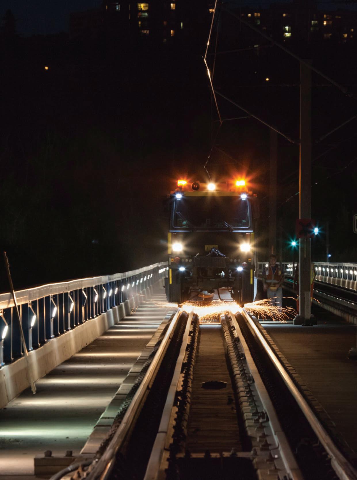
Photo


Speno accumulated a massive rail grinding experience.
We thank all the Railway Infrastucture Teams who have worked with us on so many challenging projects.


Vol. 121, No. 2
Print ISSN # 0033-9016, Digital ISSN # 2160-2514
EDITORIAL OFFICES
1025 Rose Creek Drive Suite 620-121 Woodstock, GA 30189
Telephone (470) 865-0933 Website www.rtands.com
DAVID C. LESTER Editor-in-Chief dlester@sbpub.com
JENNIFER M c LAWHORN Managing Editor jmclawhorn@sbpub.com
EDITORIAL BOARD
David Clarke, University of Tennessee
Brad Kerchof, formerly Norfolk Southern Jerry Specht, CPKC/AREMA
Scott Sandoval, Genesee & Wyoming
Robert Tuzik, Talus Associates
Gary Wolf, Wolf Railway Consulting
CORPORATE OFFICES
1809 Capitol Avenue Omaha, NE 68102
Telephone (212) 620-7200 Fax (212) 633-1165
ARTHUR J. MCGINNIS, JR. President and Chairman
JONATHAN CHALON Publisher
MARY CONYERS Production Director
NICOLE D’ANTONA Art Director
HILLARY COLEMAN Graphic Designer
JO ANN BINZ Circulation Director
MICHELLE ZOLKOS Conference Director
CUSTOMER SERVICE: 847-559-7372
Reprints: PARS International Corp.
253 West 35th Street 7th Floor New York, NY 10001
212-221-9595; fax 212-221-9195 curt.ciesinski@parsintl.com


First, please relax, as there are not going to be any major changes to RT&S, just some slight modifications. Those who have been reading RT&S for several years will remember my introduction of several new “sections” in the magazine, such as “NewsWatch” and “Special Reports.” These sections will remain available for use going forward, but as I have gotten feedback from our Editorial Board and those in the field, I discovered that some of these sections were not providing the best service to our readership. In addition, I wanted to provide coverage of passenger station work, and we will at some point, but the degree to which I wanted to cover it was not in tune with reader needs. And, in one editorial, I discussed having more focus on project work, particularly associated with our Vendor Product Spotlights (now called Vendor Spotlights) but for various reasons, there are several proprietary issues that arise when discussing details of a project, and folks weren’t comfortable with submitting a lot of project-related material.
So, what does all this mean? Regarding projects, we will still have our annual “Top Projects” issue in June. In this piece, we accept nominations for and choose around ten projects for recognition. This is one of my favorite pieces, because successful completion of projects is where everything comes together and showcases the best in railway engineering work.
Secondly, we’ll continue to build on our sponsorship/partnership with WheelRail Seminars. The work generated by this conference is a treasure trove of deep and
cutting-edge research presented by some of the industry’s best practitioners. In addition, a collection of these articles can serve as a valuable resource down the line. As you may know, WRI will divide into two seminars beginning this year: one focused on Heavy Haul and one on Rail Transit. This move will provide additional material and better focus for those who attend either. In addition, the “Principles” course that is part of each event will focus more directly on material related to Heavy Haul or Mass Transit, depending on the conference.
Third, each Vendor Spotlight will be preceded by an article about what railroads and others are doing in the field with the product category featured in the Vendor Spotlight. For example, if we have a vendor spotlight on those companies that offer friction management products and services, it will be preceded by a piece on industry practices with friction management. These pieces will be prepared by RT&S staff. We believe your review of vendor products and services will be enhanced by a broader discussion of the latest industry trends that are not vendor specific.
Finally, we will have more “RT&S Primers,” which are introductions to industry engineering practices geared toward new railway engineers and those who need a refresher. These will be written by engineering professionals, and we have a new one in this issue focused on derailment investigation, written by Gary Wolf, who, from what we’ve seen, knows as much or more about this topic as anyone in the world.
Quality articles on relevant subjects. That is the goal of this fine-tuning of RT&S content in the magazine and on the web. As always, we welcome your feedback and are interested in how you think we can make RT&S even better.
Thanks so much for your readership and support.

DAVID C. LESTER Editor-in-Chief
Yin Gao, Principal Investigator I, MxV Rail
Yuqing Zeng, Principal Investigator II, MxV Rail
Spike fatigue is just one example of the engineering challenges that railroads face while moving people and products across the continent. MxV Rail works with the railroading community to identify these issues and investigate potential mitigation strategies. We will provide updates on our efforts this coming April during the 30th Annual AAR Research Review. For details, please visit www.mxvrail.com/ conference/30th-aar-annual-research-review
Due to their ability to reduce gage widening as speed and axle load increase, elastic fasteners for timber and composite ties have gained popularity, and elastic fastening systems have been installed in many locations on North American heavy haul railroads. However, recent research has shown that when spikes have been used in conjunction with elastic fastening systems in
territories with steep grades and high-degree curvatures, railroads have been experiencing a higher frequency of broken spikes.1,2
Recent numerical modeling1 has indicated that spike breakage appears to be a result of the combined effect of the lateral and longitudinal forces being transferred into the fastening system and generating high enough stress concentrations to produce fatigue cracks. The highest stress in the model occurred at the location where the fatigue failure initiated on an actual broken spike. The spike’s position in a spike hole can cause uneven load distribution in the spikes. As indicated in Figure 1, spikes can be oriented in a variety of positions in the tie plate spike holes. Due to uneven load distribution, one spike could carry more than 70 percent of the load transferred into the plate where that spike sits. Once the spike with the highest load breaks, the load will be transferred to another spike.
MxV Rail has been investigating the causes of and potential mitigations for broken spikes that can occur on curved track. A fatigue analysis used the measured spike load level under different conditions to estimate when spike breakage would occur. The stress cycle amplitude and cycle count for the spike fatigue analysis was calculated using a rainflow-counting algorithm. The analysis showed when the spikes
theoretically could start to break and how to mitigate the broken spikes.
During testing, spikes instrumented with strain gages were developed and used in revenue service and at the Facility for Accelerated Service Testing (FAST®), Pueblo, CO, to measure the spike loading environment. The revenue service site featured trains of various weights and types to measure the spike load level based on train passage with a variety of axle loads, providing real-world loading environments for spikes. During the FAST test, instrumented spikes were installed on four commonly used wood tie fastening systems to measure the spike loading environment in all four systems.
The revenue service testing was performed at a test site with a 9-degree, 25-minute curve with a 1.8 percent grade. The curve has three main tracks, each with a history of broken spikes. The track speed was 30 mph. The traffic included trains in both directions with various axle loads.
For the FAST test, engineers selected the following four test cases to represent four typical wood tie fastening systems:
• Case 1, elastic fasteners without rail anchors
• Case 2, elastic fasteners with rail anchors
• Case 3, curve block plates with rail anchors
• Case 4, American Railway Engineering

and Maintenance-of-Way Association (AREMA) plates (traditional spike fasteners) with rail anchors
Case 1 had a history of broken spikes. Cases 2 and 3 had two potential remediation methods for broken spikes. Case 4 used standard AREMA plates that provided less rail roll resistance compared to the other fastening systems and were included for comparison. Instrumented spikes were installed only on the high-rail plates in each test case. Operating conditions at FAST were as follows:
• Six-degree curve with 0.2 percent grade
• Single track with train running clockwise and counterclockwise
• FAST train with three locomotives and 114 cars (most weighing approximately 315,000 pounds).
Figure 2 depicts a representative spike load measured at the revenue service site where each wheelset corresponded with a small load cycle in the spike, and adjacent trucks formed a large cycle. Therefore, this spike underwent four small cycles and one large cycle for each car pass. The rainflowcounting algorithm was used to determine the number of fatigue cycles and stress amplitudes. This algorithm is often used in fatigue data analysis to reduce a spectrum of varying stresses into a set of simple stress reversals.
The stress cycle average and the stress amplitudes of spikes were extracted using rainflow counting (Figure 3). The stress cycle average is a way of quantifying the average stress in one cycle, and the cycle range assesses the peak-to-peak stress magnitude in one cycle (Figure 2). The blue bars and orange bars represent the loads created by loaded cars (axle load>25 kips) and light cars (axle load<25 kips), respectively. The yellow bars are load cycles generated by a certain ratio of loaded cars and light cars. In the figure, a combination ratio of 0.5 is shown. Typically, the area in the black circle of Figure 3 resulted from large cycles, and the area in the red circle came from small cycles. Both the cycle range and cycle average of the spike load induced by loaded cars were approximately three times higher than those induced by light cars. The number of cycles was normalized by car for further fatigue analysis. A typical stress-life cycle curve (S-N curve) for 1020 steel (spike material) was used in the fatigue analysis.3
The stress resultants from both the lateral and longitudinal directions comprised the


spike stresses used in the fatigue analysis. For each test case in Table 1, the most heavily loaded spike among all the instrumented spikes was selected to calculate spike fatigue life. The spikes on elastic fastener plates presented a projected service life of only 65 million gross tons (MGT) under the heavy axle load environment. Rail anchors and curve block plates, when used as two remediations for spike breakage, extended the projected service life to both 320 MGT and 340 MGT at FAST, respectively. Based on the results analyzed from the revenue service test, light cars (<25-kip axle load) would not cause spike breakage. However, spikes under loaded cars (>25-kip axle load) only presented 35 MGT projected service life before starting to break. In addition, the fatigue analysis simulated an ideal condition where the total load transferred to a plate was evenly distributed to
all the spikes on that plate. In this scenario, the spikes could last 600 MGT before the broken spikes start to occur.
The spike loading environment was measured using instrumented spikes both at FAST and in revenue service. The spike stress data was analyzed using the rainflow-counting algorithm to calculate the stress cycle range, average, and count. A fatigue analysis was then performed to assess the spike fatigue life for different fastening systems and different axle load levels. The analysis provided the following information:
• Analysis from both FAST and revenue service tests projected that spikes on elastic fastener plates with no rail anchors would start to experience fatigue failures within 65 MGT under loaded traffic.
• Based on the spike data collected in revenue service, only loaded cars generated spike breakage. Light cars presented an infinite spike life. As long as there is heavy car traffic (>25kip axle load) in a high-grade and high-degree curve, spikes on elastic fasteners will likely experience some fatigue failures.
• Two mitigation methods (rail anchors and curve block plates) could extend spike life but neither presents a permanent fix for the spike breakage issue.
• Even distribution of the spike load could significantly increase the spike fatigue life (35 MGT to 600 MGT). Methods that generate an even distribution of loads among all spikes may provide a potential solution for broken spikes and should be evaluated.
1. Gao, Y., M. McHenry, and B. Kerchof. 2018. “Investigation of Broken Cut Spikes on Elastic Fastener Tie Plates Using an Integrated Simulation Method.” Proceedings from 2018 ASME/IEEE Joint Railroad Conference, April 18–20, 2018, Pittsburgh, PA, USA.
2. Gao, Y. 2022. “Spike Loading Environment in Various Wood Tie Fastening Systems.” Technology Digest TD22-016. Association of American Railroads (AAR)/MxV Rail: Pueblo, CO.
3. A merican Society of Mechanical Engineers (ASME). 1998. BPV Code, Section 8, Div 2, Table 5-110.1.


By Jeff Tuzik
Rail grinding is a well-established maintenance practice with multiple preventive and corrective applications. Rail milling is a more recent (introduced roughly 25 years ago) addition
to the rail maintenance toolkit, but although its use in North America has been limited thus far, it is widely used in Europe, Asia, and Australia, often in concert with rail grinding programs. While these technologies occupy a similar niche, they do not necessarily directly compete with each other and in fact often complement each other. Both have strengths and limitations, and understanding them is a necessary part of choosing the right tool for the job.

Fundamentally, rail grinding works by abrading the rail surface with the flat face of multiple cylindrical grindstones (see figure 1). The stones rotate on their axis (perpendicular to the rail) at high speed. Milling is a cutting process in which a cutter head with carbide milling inserts cuts the rail into the prescribed shape as defined by the shape of the carbide inserts (see figure 2). This is a peripheral milling process, meaning the cutter head rotates on its axis (and cuts) parallel to the rail surface.
Both grinding and milling can be used to achieve similar end-results: a running surface that is properly profiled and free of defects. “But the specific capabilities of each technology means that the details do differ,” Richard Stock, Global Head of Rail Solutions at Plasser & Theurer told those gathered at Wheel Rail Seminars’ 2024 Rail Transit conference. Differences in surface finish, production rates, logistics and overall maintenance strategy affect how and when these technologies are leveraged most effectively.
Rail grinders achieve their targeted profiles and metal removal by adjusting the angle and pressure of each grindstone or module. In this way, multiple stones can be positioned such that in aggregate, the entire transverse profile is defined (see figure 3). Larger grinders with more stones can thus cover more of the rail surface with more granularity or remove more metal in a
BOTH [RAIL GRINDING AND MILLING] HAVE STRENGTHS AND LIMITATIONS, AND UNDERSTANDING THEM IS A NECESSARY PART OF CHOOSING THE RIGHT TOOL FOR THE JOB.
single pass. Smaller grinders typically require multiple back-and-forth passes, adjusting the angles along the way, to achieve such coverage. The ability to adjust stone angles on the fly allows for “a very flexible transition between profiles and the ability to input any profile you want,” Stock said. The accuracy of rail grinders, in terms of achieving the target transverse rail profile, is typically 0.3mm or worse depending on operational conditions and required tolerances.
The process of milling instead defines the rail profile by the negative shape of the cutter head and carbide inserts. This means that each individual profile requires its own unique cutter head and


inserts. Changing out the cutter head is a process that can be done in the field but is a more involved process than the adjustments that are possible on a grinder. However, the purpose-built and static nature of the cutter heads also allows for very high profile accuracy in the range of 0.1 mm and eliminates any potential human-error or variance
in profile selection and adjustment, Stock said.
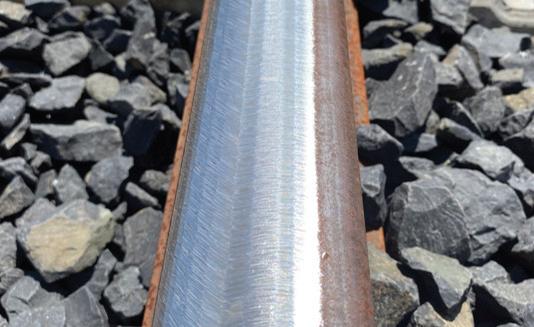
Rail grinding leaves behind a distinctive grind signature, which is in effect the pattern of “scratches” left by the rotating grindstones (see figure 4). The grind signature is affected by multiple factors:
the grit of the grindstone, the power applied to the modules, and the speed of grinder itself. It is also affected by facets left on the rail, indicating traces of each individual grindstone. Typically, the grind signature is worn away from the running band in several days or weeks of traffic, depending on MGT, but the signature can cause problems as well, Stock said. A particularly aggressive grind signature can act as a starting point for various damage mechanisms like corrugation and rolling contact fatigue (and its associated defects).
Fortunately, best-practices and hardwon experience typically enable grinder operators to dial in the various parameters required to achieve a good surface finish. Some properties stipulate an additional step of acoustic grinding or “polishing” to ensure the surface does not contribute to damage or noise generation.
Rail milling, perhaps famously, leaves behind a near mirror finish (see figure 5). Immediately post-milling, the rail surface is grooved in a pattern determined by the carbide inserts. These grooves can cause significant noise generation if not flattened and polished, Stock said. In most cases, this

post-processing is integrated into the milling machine itself. The longitudinal orientation of the polishing (and milling) processes leave behind a very low surface roughness, he said.
The productivity of rail grinding and milling breaks down into several key metrics. The first is required metal removal; depending on initial profile shape and condition, metal removal can be localized or evenly distributed across the transverse profile in order to remove defects and/or achieve the target profile. This translates to the next metric: the number of required passes and average speed per pass based on the size and capability of the machine. And there are logistical and operational time constraints, such as the time required to change grindstones/cutter heads, and to transport the machine to and from the worksite, among others. These all determine productivity as a function of finished track feet per unit of time (such as per hour or per shift), Stock said.
There are fundamental differences in grinding and milling technologies that prevent a true 1:1 comparison of their productivity; but there are some metrics
in which their functionality is sufficiently similar to warrant it. Rail grinding is a bi-directional process — that is, the machines are capable of grinding
RAIL MILLING, PERHAPS FAMOUSLY, LEAVES BEHIND A NEAR MIRROR FINISH. IMMEDIATELY POST-MILLING, THE RAIL SURFACE IS GROOVED IN A PATTERN DETERMINED BY THE CARBIDE INSERTS.
moving forward and in reverse and can apply different grind patterns on each pass completion. There is also great variability in grinder size from 8-stone grinders roughly the size of a rail transit car, to 700-foot-long 120-stone grinding trains. This variability applies to grind
speed as well. While large production grinders can grind at up to 20 mph, the average speed per pass is in the 3 to 10 mph range, Stock said. Similarly, metal removal per pass can range from 0.1 mm to 1.0 mm.
Milling differs from grinding in that it is a unidirectional process; cutter heads only cut in one direction. Speed per pass averages between 0.2 mph to 1.2 mph, Stock said. From a productivity standpoint, these lower speeds are balanced by an average metal removal of 0.3 mm to 2 mm per pass — a figure much higher than similarly-sized grinding machines can achieve, he said. As in the case of rail grinding, these figures too, are dependent on the capability of the individual machine and the specific cutter heads and milling technology it uses.
One of the main differences between the grinding and milling processes is related to the byproducts of their function. Rail grinding produces a great deal of heat, sparks, and dust. Nearly all grinders are equipped with dust filtration and collection systems, but such systems only lessen rather than eliminate the


dust. The spark streams that grinders emit (from both sides of the vehicle) have to be actively mitigated as they can and do start fires in dry conditions. For the reason of preventive (and reactive) firefighting, grinders are equipped with spark shielding and with high-pressure hoses and large water tanks. Aside from sparks, much of the waste heat generated during rail grinding is absorbed by the rail itself, Stock said. This can lead to material transformation such as the formation of white etching layers (WELs) on the rail surface which may in turn initiate ancillary defect development; “The significance of WELs produced by grinding is an area of active research, and we know that grinding isn’t the only source of WELs,” he said.
Rail milling by contrast produces no sparks or dust. Waste heat is primarily absorbed by the cutter head and metal chips cut from the rail; hence their characteristic blue hue (see figure 6). These chips are automatically collected by the milling machine and later recycled. The final polishing of the milled surface does produce a limited spark and dust stream that is typically captured by an onboard suction system. The relative “cleanliness” of the milling process can make it an appealing option for sensitive and/or confined areas, Stock said. It should be clear that there is no dichotomy between grinding and milling. Both technologies are wellsuited to freight and rail transit environments. While there is undoubtedly

IT SHOULD BE CLEAR THAT THERE IS NO DICHOTOMY BETWEEN GRINDING AND MILLING. BOTH TECHNOLOGIES ARE WELL-SUITED TO FREIGHT AND RAIL TRANSIT ENVIRONMENTS.
some overlap in their function, there are also use-cases that favor one over the other. As rail milling becomes more visible in the North American market, it’s important that education comes along with it. Part of maintaining optimal rail condition is using the optimal tools to do it.
Jeff Tuzik is Managing Editor of Interface Journal.
www.interfacejournal.com
This article is based on a presentation made at the 2024 Wheel Rail Interaction Rail Transit conference. www.wheel-rail-seminars.com
Unless otherwise noted, all images and figures courtesy of Richard Stock, Plasser & Theurer.

This edition encompasses current design methods used for steel railway bridges in both SI and Imperial (US Customary) units. It discusses the planning of railway bridges and the appropriate types of bridges based on planning considerations.
BKDMSRB2 Design & Const. of Mod. Railway Bridges $220.00*

The most comprehensive collection of definitions relating to track. Over 1500 terms from antiquated forgotten slang to today's jargon. Clearly illustrated line art enhances the text.

The Art and Science of Rail Grinding
Rail grinding saves millions of dollars every year! The Art and Science of Rail Grinding is the first book dedicated exclusively to the subject.
BKGRIND Rail Grinding

$170.00
History does repeat itself. Many of these issues are brought to life by exploring examples learned from mitigating various issues and tactics used when the NYCTA assumed control of the BMT and IRT lines.
BKNYIRT Dev. & Op. of NY’s IRT and BMT


Major Railway
the
principles of Project Management as applied to executing large programs and major projects on active railways and rail transit systems. Topics include program set-up, Work Breakdown Structures (by Systems), Phasing and its relationship to maintenance of rail operations (and maintenance), Project Status including Earned Value Analysis and forecasting, risk management, System Safety (including FRA and FTA approaches), and Systems Integration/Systems Assurance.
The book is written and recommended for railway operating officials, as well as for Engineering Officers, and PM/CM professionals.

Railway Geotechnics covers track, track substructure, load environment, materials, mechanics, design, construction, measurements, and management. It is written primarily for professionals and graduate students.

Your Guide to Railway Signals is an excellent guide for training signal personnel especially railway cross-function managers, supervisors, and support personnel. Highquality graphics and diagrams have been used throughout. Complies with all standards and commonly used practices.
BKTDH Track Data Handbook $56.50 The Track Data Handbook


Reprinted by popular demand, this book is a valuable reference for roadmasters, track supervisors, track foreman, surveyors and others involved in the planning and execution of track maintenance and construction work. Fold-out diagrams. Softcover. 301 pages.

Gain a deeper understanding of the evolution of track technology. This book presents the knowledge needed for rational design and maintenance of passenger, freight, and transit track.
BKFRTE Fundamentals of Railway Track Engineering $160.00

The Railroad What it is, What it does
The fifth edition of The Railroad: What It Is, What it Does is even more valuable than before. Inside you’ll find a comprehensive look at how today’s railroads function—from equipment to procedures and marketing to maintenance.
BKRRNN What it is What it does $49.95
By: Gary P. Wolf, Wolf Railway Consulting LLC

You get that dreaded phone call. A major derailment has just occurred on your territory. You have only been a Roadmaster for 18 months and have never dealt with a major derailment. As you get in your truck to head to the
scene, thoughts race in your head . . . What do I do when I get to the scene? What are the important first things to take care of? What can wait until later?
This article will explore step by step the 12 action items required to make a good investigation for any member of the
engineering team at a derailment site. The number one priority at a derailment site is SAFETY; safety of you, safety of your team, and safety of anyone affected by the derailment. Ensure you have all your necessary PPE, including breathing apparatus if required.
Checking curve alignment using stringlining method with 62-foot chord

Make sure the derailment investigator in charge knows you are on site and where you are working. And remember, a derailment never really stops. Equipment can be resting precariously in a jumbled position and may slip, slide, or roll over at any time, given a gust of
wind or vibrations from a D-9 caterpillar sideboom. Stay in the clear, and never put yourself in a pinch point. When arriving at the derailment scene, and hopefully before any site clearing has begun, your first priority is to locate the “point of derailment,”
or POD. This is the first indication on the track structure that a wheel left its normal running position. It could be a wheel climb mark on the gage face of the rail, or it might be a wheel drop mark coming off the gage corner of the rail when the rail rolls outward. In other
Marking off 15.5-foot stations to measure track geometry

cases, it might be the first sign of some sort of catastrophic failure, like a broken rail, axle, wheel, or coupler. It is important to nail down the POD accurately since all track geometry measurements are taken with the POD as the starting point (Station 0).
The second step at the derailment site is to determine the derailment mechanism, or how the wheel derailed. Finding the POD will assist you in determining the mechanism. The basic mechanisms of how wheels derail include wheel climb, wheel lift, wheel drop in due to gage widening, or some sort of catastrophic failure.
The third step is to determine which wheel, and car, derailed first. It is essential to establish which car derailed first in order to determine whether a defective mechanical condition may have caused the derailment. If you fail to accurately identify the first derailed car, you may never determine the root cause of the accident.
The fourth step is to accurately locate
and mark (milepost location) where the lead locomotive came to final rest after the emergency stop of the train. Estab -
YOU GET THAT DREADED PHONE CALL. A MAJOR DERAILMENT HAS JUST OCCURRED ON YOUR TERRITORY. WHAT DO I DO WHEN I GET TO THE SCENE?
lishing the stop location will allow team members to analyze the event recorder data and determine how the train was
being handled at the exact time the first wheel derailed. If you don’t know where the train stopped, it will be impossible to assess speed and train forces at the time the derailment initiated. Along with marking where the lead locomotive stopped, you should also mark where the derailed equipment came to final rest.
These first four steps are best accomplished before any remediation of the site or rerailing begins. Once you start removing track and equipment, you may never accurately locate the POD or first car to derail.
Step five involves taking a lot of photographs of the derailment. Document track conditions, such as rail, fasteners, ties, and ballast, at and surrounding the POD. Next, document mechanical components such as wheels, truck frames/bolsters, and the car body. If possible, take some overview, or panorama pictures of the entire derailment site from beginning to end.
The sixth step involves data collection. There are a number of data
sources that should be secured as part of the investigation. The track profile chart of the area and train consist are essential. Someone in transportation should download locomotive event recorder and video data. The latest track geometry data and rail flaw test data for the area should be collected. The crew people involved in the derailment should have statements recorded as to what they saw, felt, and heard at the time of the derailment. If it was a yard or switching derailment, you might want to get statements from adjacent crews or even yardmasters in the tower. Historical weather data can be important in derailments possibly involving track buckle, washout, wind blowover, or winter pull aparts. The mechanical department should try to secure any recent car repair billing records on the first car to derail. And finally, wayside detector data such as Wheel Impact Load (WILD), truck hunting, hot box detectors, or truck performance should be downloaded as appropriate. There could be other data sources that your railroad has access to that should be considered for inclusion in the derailment file.
Once the site is secured, and sufficient equipment has been moved, it is now time to complete step seven which involves inspecting the track structure and comparing your findings against the FRA track safety standards. There are two important components of the track structure. First, you must assess the track geometry; and second, you must assess the track integrity. The FRA track safety standards contain regulations for the geometry of the track, such as gage, crosslevel warp and twist, track surface, and horizontal alignment. Measurement stations should be set up 15 ½ feet apart. At a minimum, go back 15 stations from the POD (Station 0) in the direction the train was approaching, and measure five stations beyond the POD if possible. For high-speed passenger derailments, you might want to measure 40 or 50 stations of data.
Other parts of the FRA track safety standards address the integrity, or strength, of the track structure. You should evaluate, at a minimum, the rail and joint bars, spiking patterns, anchoring patterns, tie condition, ballast, and drainage. Compare your findings against the FRA regulations.
Remember that the FRA regulations are minimum safety standards, and the regulations do not cover a number of topics that could be causative in the derailment. A combination of track conditions might be the root cause of the derailment, even though you comply with all the individual standards for each station.
In step eight, the first derailed car, and its trucks, should be carefully measured and evaluated to determine if a mechanical failure might be the root cause. Once the first derailed car is identified, an effort should be made to collect as many of the truck components of that car as possible. Important truck components include bolsters and sideframes, wheels and axles, bearings and bearing adapters, friction castings, springs, and side bearing elements. Unusual wear conditions around the centerbowl rim, behind the bolster gibs, and on the springs should be documented. The wear may not be a defect but could indicate poor dynamic performance of the car during truck hunting, harmonic rocking, or truck warp during curving.
Step nine involves evaluation of human performance and operation factors. Locomotive event recorder data should be compared against best operating practices. Crew performance should be compared against safety, operating, and train handling rules. Step nine should also include a close scrutiny of your railroad’s train make up rules and practices.
Once you have completed steps 1-9, you should be in position to compare your findings against any and all applicable operating/safety rules, FRA track safety standards, and AAR mechanical standards. This is step ten. If you have done a good job taking all the essential measurements and evaluations, at this point, the root cause should be evident.
In some cases, there could still be question marks, especially where you have found some track conditions not yet condemnable, and some mechanical conditions that are approaching condemning limits. In this case, simulation analysis can help determine which conditions are most complicit in causing the wheel to derail. Simulation models such at VAMPIRE, NUCARS, TOS, and TOES are all valuable models for derailment analysis and confirmation. In some derailments, there could be questions about a possible fatigue failure of the rail or a wheel. In these cases, you should have a professional metallurgical lab familiar with rail components perform a failure analysis to verify a potential cause.
After going through the evaluation process in step 10, with perhaps additional simulation or metallurgical analysis, you are now in position to identify the root cause and any contributory causes. The root cause is the one condition, that if you remove it from the mix, the derailment does not occur. Contributory causes alone are not sufficient to cause the derailment but enhance the possibility of derailment. If you cannot


make the root cause determination here in step 11, it generally means that you have failed to accurately identify the
POD, or the first car to derail. You might have to start over at step one. Finally, in step 12, you must develop
corrective actions to prevent a recurrence of this type derailment. Corrective actions can range from repairs, removal of defective equipment or conditions, new rules and regulations, training, and improved inspection procedures. And check back in 6-12 months to ensure those corrective actions had the desired effects, and there were no unintended consequences.
If you diligently perform all twelve steps of this process, 99.9% of the time the root cause will fall in your lap and be obvious. Leave out one or two steps, and you may never determine the root cause. Derailment cause finding is not difficult. It just takes getting dirty, determination, knowledge, and the ability to work in an unbiased manner.
Note: Gary Wolf has investigated over 3,000 derailments in his 54-year railroad career, and is author of the only textbook on derailment investigation entitled The Complete Field Guide to Modern Derailment Investigation

Track Safety Standards Subparts A-F
Track Safety Standards, contains the Track Safety Standards, Subparts A-F, for Classes of track 1-5. The standards cover general information, Roadbed, Track Geometry, Track Structure, Track Appliances and Track-Related Devices, and Inspection. Includes Defect Codes. Updated December 28, 2023
BKTSSAF Track Safety Standards, Subparts A-F $13.95 Only $12.50 for orders of 50 or more!

FRA Part 237 establishes Federal safety requirements for railroad bridges. This rule requires track owners to implement bridge management programs, which include annual inspections of railroad bridges, and to audit the programs. Part 237 also requires track owners to know the safe load capacity of bridges and to conduct special inspections if the weather or other conditions warrant such inspections. Updated December 28, 2023
BKBRIDGE Bridge Safety Standards $14.00
Only $12.60 for orders of 50 or more!

This reprint includes the FRA's Railroad Workplace Safety Standards addressing roadway workers and their work environments. These laws cover such things as: personal protective equipment, fall protection, and scaffolding for bridgeworkers; and training issues. Also includes safety standards for on-track roadway vehicles. Updated December 28, 2023
BKWRK Railroad Workplace Safety $13.95 Only $12.50 for orders of 50 or more!


The Track Safety Standards Calculator is a must for anyone who works on track. This slide rule type calculator contains many of the details for Classes of track 1- 5. Deviation from uniform profile and from zero cross level. Difference in cross level. Compliant with part 213.
Track Calculator $12.50
Only $11.25 for orders of 50 or more!


Suppliers showcase their best in rail grinding and milling.
By Jennifer McLawhorn, Managing Editor
Atheme for this month, one of the Vendor Spotlights focuses on rail grinding and milling. Grinding offers a corrective reprofiling of the rail while a milling machine rotates against the rail to carve a specified shape. On page 8 of this issue, our readers can be informed of a technical analysis on rail grinding and milling based on a 2024 Wheel/ Rail Interaction presentation from Jeff Tuzik.
With that in mind, RT&S features several players in the rail grinding and milling game. Loram says, “Rail grinding and milling play crucial roles in maintaining rail infrastructure, enhancing overall rail safety, and minimizing service disruptions. Loram, through its specialized services and cuttingedge equipment, significantly contributes to the reliability and longevity of railway systems around the globe. A standout
innovation in Loram’s lineup is the RGX, a new rail grinder model designed specifically for the metro industry. This state-of-the-art machinery features advanced engine technology and a more compact design, providing railways with a lighter axle load. Despite its smaller dimensions, the RGX retains the power and productivity that Loram is renowned for. Designed to meet various global network requirements, the RGX can
Orgo-Thermit uses a 12 stone Hi-rail vehicle to grind on open track.

navigate tight curve radii and adhere to stringent clearance diagrams. Its light axle loads allow it to be both nimble and versatile, easily addressing diverse grinding conditions. A unique design element enables the machine to operate without staff needing to disembark for set up or pack away, significantly reducing risk and enhancing workplace safety. Moreover, the RGX can be outfitted with state-of-the-art measuring equipment, such as systems for analyzing transverse and longitudinal rail profiles. This capability ensures that all pre- and post-treatment outputs are documented,
verifying that the grinding work meet the required specifications. Doing so facilitates the prompt reopening of the network for safe train operation. Metros recognize that rail grinding is vital for eliminating surface defects, which, if left untreated, can lead to noise and ride quality issues. Ultimately, maintaining reliable service and public satisfaction makes timely rail grinding not just necessary but essential.”
Orgo-Thermit, a Goldschmidt company, tells RT&S it “is proud to offer a complete grinding service. With our ability to analyze the track using our proprietary
Eddy Current system and the Trackscan Mira with up to 8 probes on each rail, we can get a full picture of the RCF in the customer’s track and optimize a grinding or milling program accordingly. The probes measure from the gauge corner, where most RCF originates, over the head of the rail to ensure a complete analysis. This analysis enables us to ensure that our efforts are focused on the most affected areas of their railroad as opposed to a strategy where a complete system is ground. This saves the customer both money as well as the required track time to perform the work. By using this system, it ensures that maintenance is focused on the areas of their track with the most need. Our Eddy Current system can be offered as both a trolley as well as a mounted system. Based on the data gathered, we can use our 12 stone Hi-rail vehicle which offers best in class performance for embedded track as well as being able to grind on open track. With its unique ability to get on and off track in less than a minute at crossings, it offers a level of flexibility that is unparalleled. We have been using the combination of Eddy Current Technology with our grinding vehicle to provide service for a number of Transit agencies. These Transit agencies have benefitted from a focused grinding program to target the specific areas that need addressing which saves money by reducing the RCF as well as not grinding areas that do not need grinding, saving on overall maintenance costs.”
To meet the challenges of modern datadriven maintenance, Linsinger says it “has developed the Linalyzer measurement system, which integrates the most essential measurement techniques for rail maintenance. The goal of this system and its software is to support railway operators by providing data-driven insights into the necessary maintenance measures. This helps extend the service life of the rails and ensures track safety. The new measuring system is based on proven technologies, which Linsinger has used in its rail milling trains for more than 20 years. The newest sensor generations enable measurements with unprecedented accuracy. These technologies are incorporated into a modular design based on a vibration decoupled support bogie that enables highly accurate measurements even under difficult conditions. This bogie is theoretically able to go at least 60 kilometres per hour during measurement runs, and even switches and crossings can be passed effortlessly. The modular design allows the customer to tailor the equipped measurement systems to his

needs. Beside longitudinal profile, transverse profile and crack depth, also rail head height, quality index, track width, and acoustic roughness are available for selection. On top of the newest measurement sensors and algorithms stands a new user interface, which brings user-comfort to the next level. This software is designed to make the machine operator’s life as easy as possible. Measurements start and stop automatically with the milling process. All measurement systems are integrated into a single piece of software, therefore multiple laptops, multiple inputs or even inconsistent measurement-run data are a thing of the past. Keeping track of measurement data of multiple measurement systems is as easy as never before, due to our innovative visualisation techniques.”
RailWorks says it “delivers turnkey switch and crossing rail grinding services for railroads and transit lines. With the help of our experienced team, you can increase the life of your rail system, improve their reliability, and maximize the efficiency of your entire rail network. Staffed with experienced crews, our grinding teams are known as being among the safest and most customer driven in the industry. A properly planned and executed rail grinding program will bring with it numerous safety and economic benefits which include increased rail life, improved wheel/rail interface, and reduced wheel/rail noise. The life of railroad assets is increased when a grinding program is in place. Most importantly, when track is properly maintained with a rail grinding
program, it can significantly cut down on fuel consumption and reduce broken rail derailments. The machines can effectively grind switches, guarded curves, and road crossings. Some benefits and features of this turnkey solution are independent hydraulicallypowered grinding units, Jupiter II Control System, hydrostatic propulsion system, full computerized control, dust collection
system, pneumatic braking system, water spray fire control system, and comfortable control cabins. RailWorks’ grinding services provide a beneficial package that will meet your distinct requirements for safety, quality, and on-time performance.”
ROBEL says its “family of battery and gasoperated machines [is] specifically designed for surface grinding, switch blades, frogs, stock, and check rail applications. Previously, multiple machines were needed for these tasks. Now, ROBEL introduces the innovative 13.63 Modular Switch Grinder— a single frame that adapts to all grinding applications. Whether you need flat stones, web grinding, or standard cup stones, you can simply swap the motor unit based on the task at hand. ROBEL North America has established a strong reputation with Class I Railroads, Transit Authorities, Contractors, and Short Line Railroads by providing reliable and safe equipment. Our 13.49 0-Point Profile Grinder demonstrated its excellence on Florida’s Brightline project, thanks to its unique 0-point system that eliminates over-grinding of welded rails. Any operator can achieve precision grinding results. Both machines offer versatility and efficiency. They can be powered by a robust 2,300Wh battery, delivering over an hour of continuous use, or an EPA-approved four-cycle gas engine, ensuring you’re covered for any project.”


By Jennifer McLawhorn, Managing Editor
Seemingly simple, clearing brush and other vegetation off the rightof-way is a significant area of track maintenance. Of course, it appears to be a no-brainer. Trains need to be unimpeded by obstacles in order to make the necessary routes. With the growth of rail networks, keeping up with overgrown vegetation is not something a handful of crew members can do without the right equipment. This equipment encompasses just about anything from handheld tools to large excavators.
While we happen to be in the middle of winter with snow covering quite a bit of the south and east United States, railroaders will begin to turn their attention to vegetation management when temperatures warm up. Class Is, short lines, and passenger rail will need to keep up with this need for track maintenance. Two vendors, Industry-Railway Suppliers and RCE Equipment Solutions, offer such solutions.
Industry-Railway Suppliers, founded in 1966, tells RT&S it “is the distribution representative of Supertrak machines, and a North America distributor of AREMA track tools, abrasives, heavy railroad equipment, work equipment wear parts and mechanical shop tools. Supertrak is a 30-year CATauthorized OEM that specializes in upfitted machines with a small footprint and high
performance. Supertrak builds custom equipment for a range of applications, including vegetation management, trenching, cable retrieval, monorail work tractors, and custom utility trucks. One standout product is the Supertrak SK170RR Hi-Rail Excavator. Built on a CAT313 hi-rail platform, this machine is powered by a 170-horsepower engine with a dedicated high-flow system and reversing fans for versatile functionality. It features fourwheel drive and brakes for better handling, and its compact size allows for transport without the need for special permits, making it ideal for land clearing and vegetation management in remote areas. The SK170RR also meets national railroad safety standards. When equipped with the hydraulic-powered Bull Hog mulcher, the SK170RR becomes an even more powerful tool. The mulcher clears trees and heavy brush along railways or prepares large areas for new track installation. Its low-maintenance design enhances tool durability, with options for knives or carbide teeth. The mulcher also offers a custom variable displacement motor and three rotor choices to suit different application needs.”
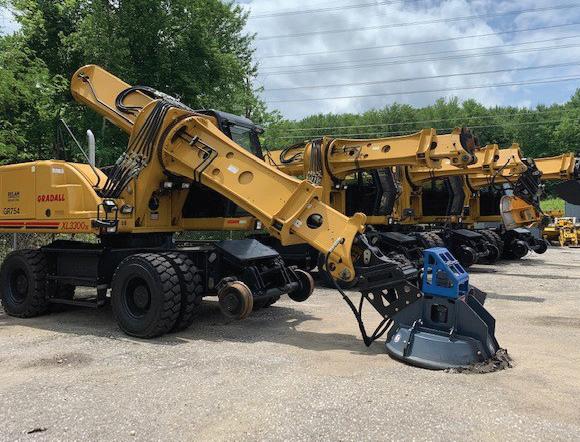
RCE Equipment Solutions “is a provider of hi-rail and dedicated on-track construction equipment. RCE will often upfit the full size RAILAVATOR with a rotating drum mulching mower providing 36” of cutting width.”
The vendor tells RT&S that “the mulching mower makes quick work of moderate to heavy brush clearing while leaving behind finely processed material that provides ground cover. Recently, RCE was asked by a Class I railroad to provide a mower solution on a smaller hi-rail excavator. Due to its compact size and ease of mobility, the John Deere 50 P RAILAVATOR was chosen. The 50 P features an RCE exclusive expandable undercarriage, providing the ability to straddle rail and offer exceptional stability while working over the side. The Deere 50 P RAILAVATOR was fitted with a Deere ME36 mulching mower. The ME36 functions similar to mulching heads found on full size excavators but is lightweight and perfectly matched to the hydraulic output of the 50 P. With 50 P’s enhanced over the side stability and ability to maneuver in tight areas, this small RAILAVATOR saves hours of hand work brush clearing near bridges, signal stands, embankments, and countless other hard to reach places. When the work is complete, the 50 P, weighing in at just under 16,000lbs, can be loaded onto most any medium sized tag trailer and moved to its next job. The 50 P RAILAVATOR, along with many other units, is available for sale and is also part of the RCE rental fleet.”

BILL RIEHL AREMA President 2024-2025
Focusing on safety is not new for the President’s article, but it remains an important topic specifically when life comes at you fast and hard. Are you ready? This was a lesson the Riehl household relearned on the first of January when Miss Deborah fell off her new bike and broke her leg in a most spectacular fashion. She is at home recovering from her second surgery and has a solid prognosis for a full recovery, but it will take time. In the interim, we are blessed with good insurance, strong support from our employers, and a great network of concerned family and friends who look in on her and help when I need to be in the office.
Whether you believe in “Safety First” or “Safety Third” (Credit Mike Rowe), I think we can all agree that safety is a critical part of the value stream we create for our owners. After all, those investors chose our companies for a return on their investment. We cannot deliver that return if we disregard safety and stack up the claims cost that result. So in the Riehl view of the world, I believe we create value for our owners in three ways: Work safely and eliminate all the costs associated with an incident and its fallout. Do it right the first time and eliminate the cost of poor quality in planning and execution. Be efficient and make good use of the resources available to eliminate the costs and time lost from poor decisions. If we can do all three, productivity and economy naturally result, and
we deliver value for our owners from our piece of the enterprise.
For the safety portion of the value stream, are we doing all we need to do to ensure our teams are operating safely? Or are we assuming too much? In the case of the January first incident, the morning’s job was an orientation ride on our new E-Bikes. The bikes were purchased online in December and assembled per the manufacturer’s instructions prior to us going north for the holidays. We got home on the 30th and unpacked on the 31st. On the morning of the first, we watched the manufacturer’s “first ride video” to get oriented with the bikes and their controls. We immediately put on our helmets and headed out for our first ride. After an orientation loop in the neighborhood, we stopped and checked we were good and headed out towards our camping friends to show them our new toys. A mile into this phase of the day’s activity, she hit some rough road, lost control and crashed, resulting in a tibial plateau fracture, type VI, and the accompanying wounded pride.
So, let’s walk through the usual incident investigation details: The time was approximately 12:30 pm EST. The weather was cool and clear. Traffic on the road was light, and she was riding in accordance with Florida regulations with respect to bicycles. The bikes we replaced were purchased in 1992. Deborah is a year or so older than 29, so she is an experienced bike rider. The new bikes we purchased were based on friends’ recommendations and our previous rides on their bikes. So, she is not a complete novice on this bike. She was wearing the appropriate personal protective equipment for the ride. The bike was operating in gear 6 and pedal assist Level 2. The approximate speed at the time of the crash was 10 MPH, well below the bike’s top speed of 28 MPH. Post incident inspection of the bike shows no defect in the bike other than damage from the fall. Post accident reenactment on similar riding conditions could not replicate any loss of stability or control.
By all measures this accident shouldn’t have happened. An experienced rider,
using properly maintained equipment and operating well below the equipment’s capabilities lost control and crashed. How many times do we see similar incidents in the workplace? How many times do we pass them off to chance? Is this acceptable or should we be digging deeper into these “one-off” events? I argue the most powerful question in any investigation is “Why?” We need to keep asking “Why” until we get the right answer, not the convenient answer.
In the case of our crash, it turns out these bikes are not very friendly to a light grip on the handlebars. In discussing the wreck with the same friends whose bikes we had previously ridden, they shared their experience that the lack of firm and uniform grip on the handlebars can lead to loss of control. They attribute this to the lack of rake in the front forks. This sent me on a Google quest to see what I could find on the topic and ultimately came up short. That said, there may be something here. Deborah reported a wobble out of the front wheel before the crash. I also found her phone on the road approximately 8 feet from where she fell. Did she see her phone begin to fall from its cradle? Did she attempt to control that and in so doing loosened her grip on the handlebar? Is that what led to the loss of control she experienced? Based on our friend’s input, this is highly likely.
So, what can we learn from this? First, when is a safety briefing really done? Our friends had actionable information regarding the safe operation of these bikes. Why wasn’t that information included in our pre-ride briefing? Second, never settle for the easy answer when investigating an incident. It would have been easy to accept the “she hit a rough spot in the road” answer. Had we not dug further and learned about the need for firm grip on the handlebars, would we repeat the crash on our first ride following her recovery? “Why” is the most important question. Don’t be afraid to ask it. Finally, do you have a plan? Life comes at you fast. Are you ready? What if your significant other gets hurt on the job or just having casual fun. Are you ready for the fallout of the long road to recovery in a non-ADA friendly house?
Register online now and skip the line for the AREMA 2025 Railroad Bridge Symposium on February 4-6 in Fort Worth, TX. Reserve your seat and be ready for the latest advancements in railroad bridge structures. For more details, visit www.rbs25.arema.org.
Booth and sponsorship sales for the AREMA 2025 Annual Conference & Expo are now open. Gain recognition at this key industry event in Indianapolis, IN, September 14-17. For details and to secure your spot, visit conference. arema.org.
Is your Library up to date? Order the 2025 Communications & Signals Manual
MARCH 4
Committee 4 - Rail Jacksonville, FL
MARCH 3-4
Committee 38 - Information, Defect Detection & Energy Systems Shreveport, LA
MARCH 5-6
Committee 39 - Positive Train Control Shreveport, LA
MARCH 20
Committee 12 - Rail Transit Virtual Meeting
APRIL 17
Committee 12 - Rail Transit Virtual Meeting
APRIL 27-29
Committee 11 - Commuter & Intercity Rail Systems Seattle, WA
APRIL 27-29
Committee 17 - High Speed Rail Systems Seattle, WA
APRIL 29
Committee 30 - Ties and Fasteners Pueblo, CO
APRIL/MAY
Committee 14 - Yards & Terminals Philadelphia, PA
today. With over 109 new, revised, reaffirmed, or extended Manual Parts, it’s the perfect time to get your copy of the 2025 Manual. Order online now at www.arema.org.
Download the AREMA 365 App for essential rail resources and networking opportunities. Easy access to news, events, and educational materials lets you stay informed and connected to the industry. Download it today by searching for AREMA in your phone’s app store.
If you’re looking for a podcast to binge, listen to AREMA’s Platform Chats. It features guests from every aspect
of the railway industry. Catch up on all four seasons available on all your favorite listening services today.
Leverage the power of your trusted association’s Railway Careers Network to tap into a talent pool of job candidates with the training and education needed for long-term success. Visit www.arema.org/careers to post your job today.

MAY 5-7
Committee 5 - Track Seattle, WA
MAY 13-14
Committee 15 - Steel Structures Lafayette, IN
MAY 15
Committee 12 - Rail Transit Virtual Meeting
MAY 20
Committtee 9 - Seismic Design for Railway Structures Chicago, IL
MAY 20
Committee 28 - Clearances Fort Worth, TX
MAY 22-23
Committee 8 - Concrete Structures & Foundations Tucson, AZ
JUNE 19
Committee 12 - Rail Transit Virtual Meeting
Join a technical committee

JUNE 27-28
Committee 24 - Education & Professional Development West Point, NY
JULY 17
Committee 12 - Rail Transit Virtual Meeting
JULY 30-31
Committee 7 - Timber Structures Overland Park, KS
AUGUST 21
Committee 12 - Rail Transit Virtual Meeting
SEPTEMBER 14
Committee 14 - Yards & Terminals Indianapolis, IN
SEPTEMBER 17-18
Committee 39 - Positive Train Control Indianapolis, IN
NOVEMBER 12
Committee 28 - Clearances Virtual Meeting
Joining a technical committee is the starting point for involvement in the Association and an opportunity for lifelong growth in the industry. AREMA has 30 technical committees covering a broad spectrum of railway engineering specialties. Build your network of contacts, sharpen your leadership skills, learn from other members and maximize your membership investment. If you’re interested in joining a technical committee or sitting in on a meeting as a guest, please contact Alayne Bell at abell@arema.org.
For a complete list of all committee meetings, visit www.arema.org.
Chair: Peter W. Fedun, PE, Senior Project Manager, KKCS, Inc.

1. Why did you decide to choose a career in railway engineering?
To be honest, I did not intentionally choose a career in railway engineering. I was raised in a simple blue-collar home, and it was my Dad’s dream that I would be the first to receive a college education. Since attending college was “mandatory,” and I had an aptitude for math and science, engineering became the obvious path forward. I was out of my element when I arrived at school. But after figuring out the keys to success, I managed to get an excellent engineering education that opened doors to a bright future, and I launched my career working for a
prestigious consulting firm based in Manhattan. As a young structural engineer working in the center of the universe, I was privileged to be an apprentice to many talented professionals on a wide variety of projects. After being exposed to railroad bridges, I never looked back.
2. How did you get started?
I launched my railroad career by inspecting, rehabilitating, and designing railroad bridges under the guidance of extraordinary engineers. I learned valuable lessons, which included drawing scale schematics of proposed bridge designs before
performing design calculations or running computer models, which were subsequently used to validate the integrity of my schematics that looked structurally correct on paper. After developing a solid foundation as a designer, I accepted a position with a newly formed transit agency in Texas. The agency experience opened my eyes to a broader and extremely interesting world of building a new light rail transit system in an urban environment that encompassed a multitude of complex disciplines.
3. How did you get involved in AREMA and your committee?
I had been relying on the AREMA Manual as a design reference for numerous years and eventually learned more about the association through industry peers who shared their membership experience and encouraged my participation. I was intrigued about the possibility of sharing knowledge and immediately thought it would be rewarding to make contributions to the Rail Transit Chapter. Not surprisingly, my supervisor was very supportive. I joined AREMA in 2005 and became a member of Committee 12 in 2006. My experience with AREMA far exceeded my expectations, and I credit this organization for continuous education and a vast network of professional associates that solidified my career.
4. Outside of your job and the hard work you put into AREMA, what are your hobbies?
Surprisingly, my childhood hobby was model trains. As an adult, I transitioned to biking, hiking, home repair projects, and raising a family. Although I am a strong mass transit advocate, I was a young man during the muscle car era, so cool cars have always been a background hobby. After getting all my children through college, I finally purchased my dream car.
5. Tell us about your family!
I am blessed with a lovely wife Amy who has tolerated 32 years of transit projects, household moves, and an excessive amount of workrelated travel. In addition to being a saint and maintaining the Fedun household, Amy taught math and Mandarin to high school and college students. We are proud parents of three young adult children: Charlotte, who resides with her husband in Richmond; Michelle, who resides with her husband in Chicago; and Andrew, who resides in Brooklyn.
6. If you could share one interesting fact about yourself with the readers of RT&S , what would it be?
In my early thirties, I received an invitation to work in Taiwan on that country’s first heavy rail
transit system. I had never traveled abroad, and after considering the offer for one evening was absolutely enthralled by this potential opportunity for adventure. Several weeks later, I woke up in a completely foreign country with no Mandarin language skills. There was no Internet, and rare international telephone calls had to be placed through an operator. Fortunately, the project office was an international Englishspeaking office – sort of. This experience was certainly one of the highlights of my career, and I believe the obligation to provide technology transfer was fully reciprocal because I probably learned more than I was able to share. The initial Department of Rapid Transit Systems rail project was a massive 88-kilometer system with 79 passenger stations. My contributions were small but I am still proud of the finished product.
7. What is your biggest achievement?
After some reflection, I found it difficult to identify a singular big achievement. I was truly fortunate that my Dad had a vision and insisted that I obtain an education, which led to a rewarding career and a comfortable life. After obtaining adequate skills and experience, my greatest achievements were derived while mentoring young professionals and watching them succeed. The most gratifying experiences were based on informal or casual relationships. Although in sincerity, there were unsuccessful interactions and disappointments. However, it is a great achievement to observe young professionals realize success due to shared experience, advice, or through offers of opportunity that my employment positions occasionally permit.
8. What advice would you give to someone who is trying to pursue a career in the railway industry?
There are many talented and highly skilled senior professionals in our railway industry. Do not be intimidated. Ask questions, and keep asking questions until you have complete credible answers. I have over 40 years of experience, and I am still learning and asking questions.
Get PDHs at your Own Pace with AREMA’s On Demand Education
Access to important professional development content is just a few clicks away with AREMA Education. Our On Demand content spans many disciplines of PDH accredited courses that allow you to get your PDHs by learning from experts online without leaving your office.
1. LEARN MORE
Studies show that participants learn more while taking On Demand courses as you can skim through the material you understand and take more time in the more challenging areas.
2. GET INSTANT ACCESS
With AREMA On Demand courses, you don’t have to wait to learn and get your PDH’s as they’re available instantly after purchase.
3. CONVENIENT AND FLEXIBLE
Above all things, On Demand education is meant to take at your own pace and on your time. Study from anywhere in the world, whether from your office or the convenience of your sofa.
4. COURSE VARIETY
AREMA On Demand education offers a wide variety of topics for all studies of the railway engineering community.
Register and Start Learning today at www.arema.org.
BECOME A MEMBER AND SAVE
Not an AREMA member? Join today at www.arema.org and get discounts on all AREMA Educational Offerings, from Virtual Conferences to our Webinars.
Brandt Road Rail
Linsinger Maschinenbau Gmbh
Loram Maintenance of Way
Plasser American Corp
Railway Educational Bureau Relam
Speno International SA
PHONE #
301-459-3200
306-791-7541
4367138840143
763-478-2627
757-543-3526
402-346-4300
770-335-9273
41 22 906 46 00
E-MAIL ADDRESS marketing@arema.org MHaliwyz@brandt.ca marketing@linsinger.com alexis.b.nubbe@loram.com plasseramerican@plausa.com bbrundige@sb-reb.com jroberts@relaminc.com info@speno.ch
This section has been created solely for the convenience of our readers to facilitate immediate contact with the RAILWAY TRACK & STRUCTURES advertisers in this issue. The Advertisers Index is an editorial feature maintained for the convenience of readers. It is not part of the advertiser contract and RTS assumes no responsibility for the correctness.


Plasser American contracting services will provide the next level of rail maintenance through the innovative Romill Urban 3 E ³ milling machine to Transit Systems as well as Freight Railroads in North America. The innovative Romill Urban 3 E ³ high-performance milling machine incorporates the next generation of electric rail milling. The Hybrid drive system with high capacity batteries will provide hours of emission-free operations with the integrated diesel engine. This provides the ability to charge the batteries and operate the machine continuously. Featuring the revolutionary new cutter head design for longer tool life and extended operational capabilities along with state-of-theart measurement technology. This compact layout fits into the tightest subway tunnels and allows easy road transportation.


