A(BouT) Building Technology periodical for the Building Technologist
featuring
Dr. Mariana Popescu; Kengo Kuma and Associates; Ir. Anna Konstantopoulou; SUNTEX: Anna J. Wetzel, Huub Visser & Pauline van Dongen; Giulia Procaccini; i-Mesh : Luciano Ambrosini, Alberto Fiorenzi
BT Spotlight featuring Simos Maniatis , Sanguk Ryu, Masonry Construction Conservation Survey, and Breathable Biobased System
Cover page
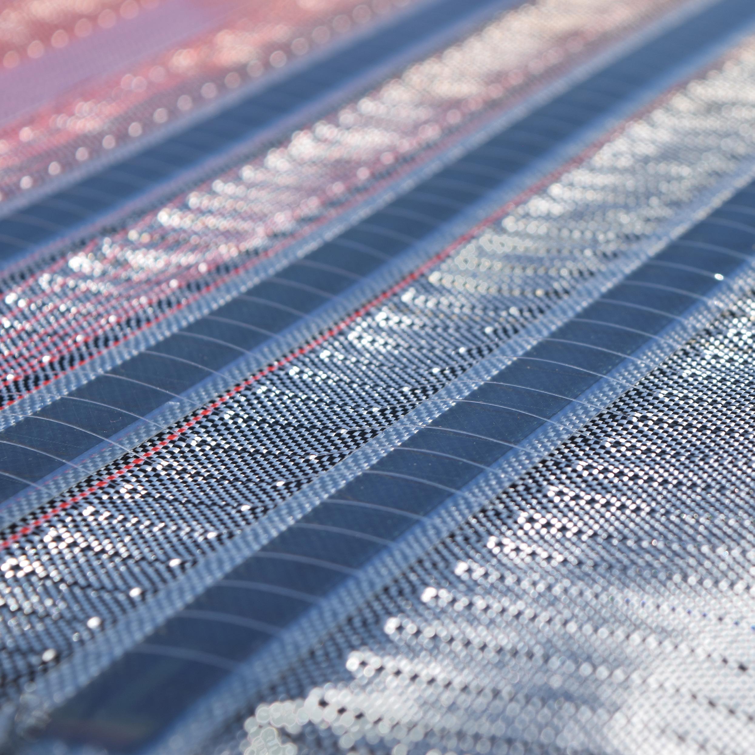
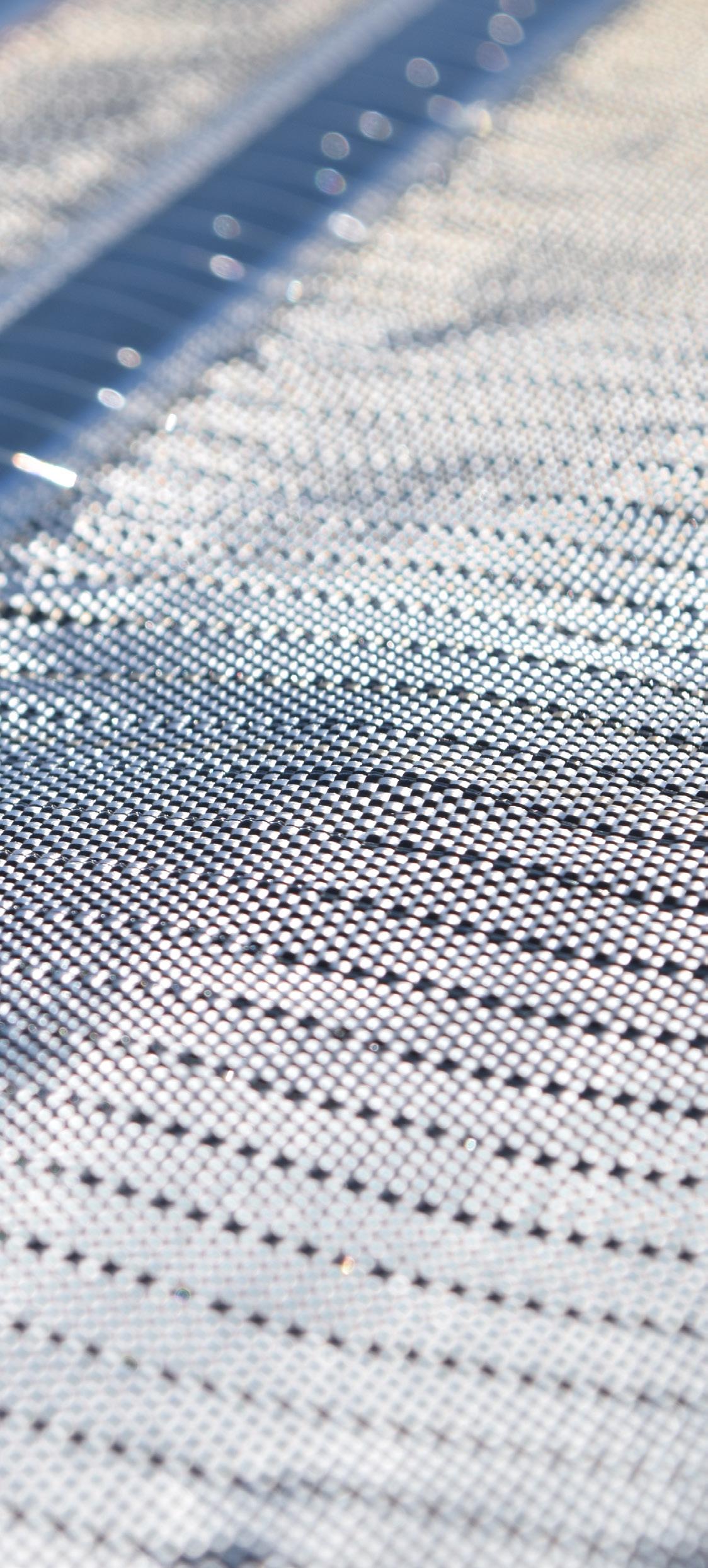
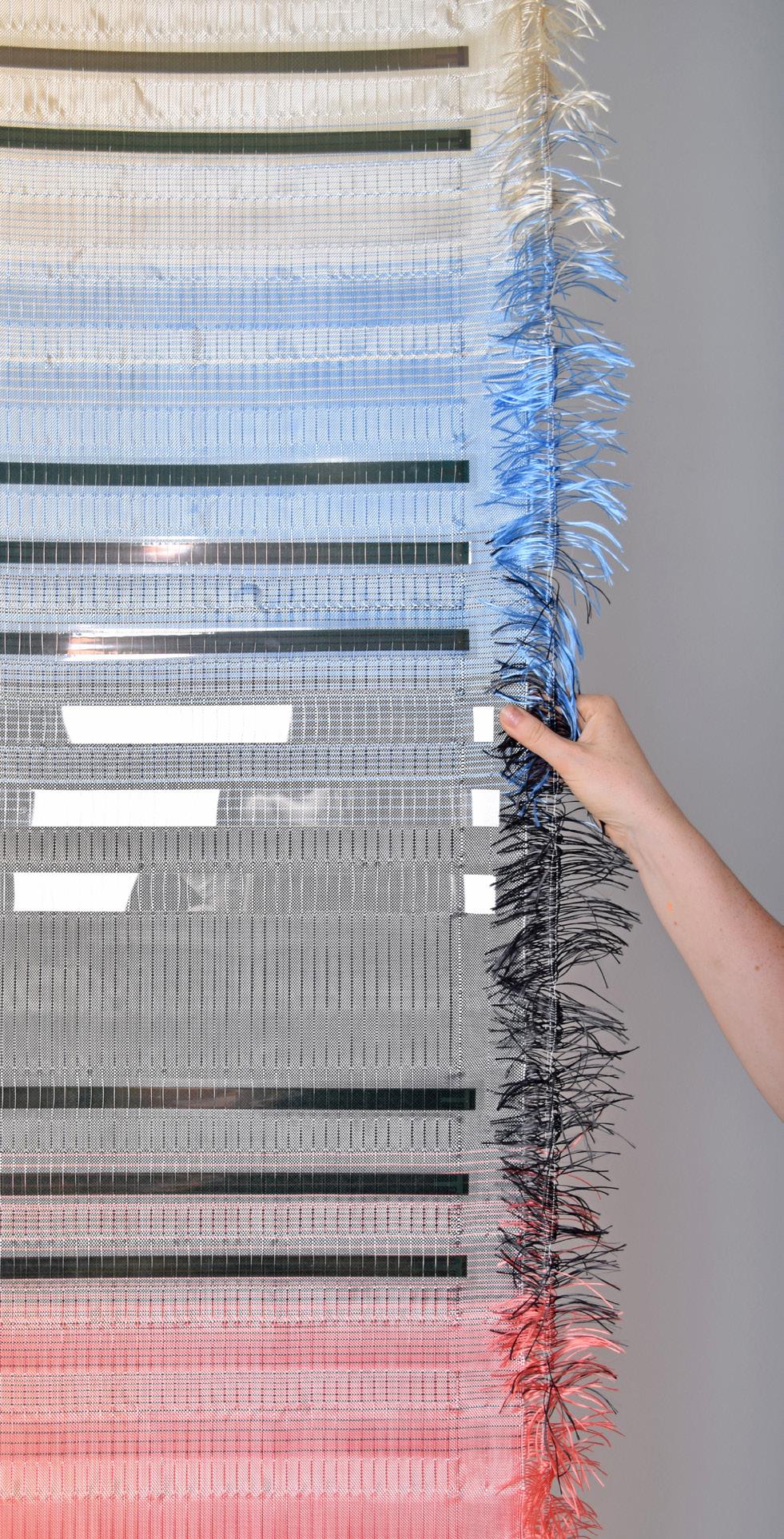
SUNTEX
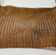
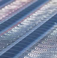
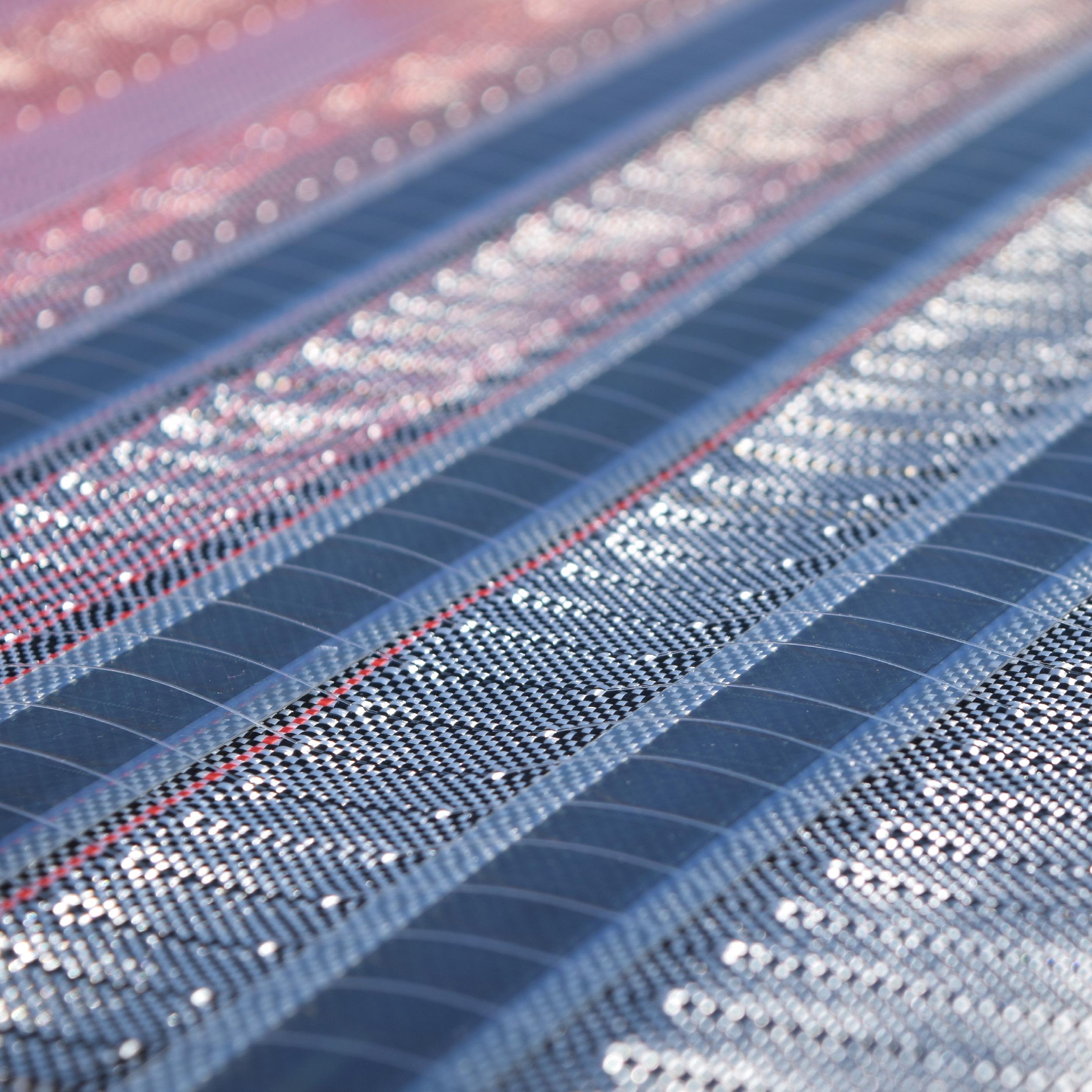
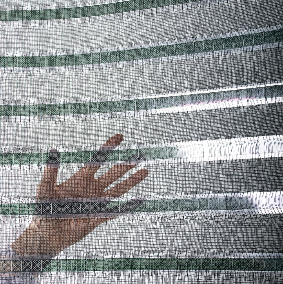
The cover image features a close-up of SUNTEX, an innovative energy-generating textile invented by Pauline van Dongen and developed in collaboration with Tentech. This advanced woven technical textile combines thin-film organic photovoltaics (OPV) with recycled PET yarns. Designed for architectural use, its lightweight, deployable nature enables it to capture solar energy from large, untapped sunlit areas, such as public squares, stadiums, and high-rise buildings.
This edition of Rumoer highlights SUNTEX's dual functionality as a shade cloth and energy generator, offering the potential to cool urban environments while enhancing the energy efficiency and aesthetics of our cities.
Studio Pauline van Dongen | Tentech
RUMOER 86 - TEXTILES IN ARCHITECTURE
1st Quarter 2024 30th year of publication
RuMoer
RuMoer is the primary publication of the student and practice association for Building Technology ‘Praktijkvereniging BouT’ at the TU Delft Faculty of Architecture and the Built Environment. BouT is an organisation run by students and focused on bringing students in contact with the latest developments in the field of Building Technology and with related companies.
Every edition is covering one topic related to Building technology. Different perspectives are shown while focussing on academic and graduation topics, companies, projects and interviews.
With the topic 'Textiles in Architecture', we are publishing our 86th edition.
The Rumoer Committee is open to all students. Are you a creative student that is eager to learn about the latest achievements of TU Delft and Building Technology industry?
Come join us at our weekly meeting or email us at rumoer@praktijkverenigingbout.nl
Circulation
The RuMoer appears 3 times a year, with more than 150 printed copies and digital copies made available to members through online distribution.
Membership
Amounts per academic year (subject to change):
€ 10,- Students
€ 30,- PhD Students and alumni
€ 30,- Academic Staff
Single copies
Available at Bouw Shop (BK) for :
€ 5,- Students
€10,- Academic Staff , PhD Students and alumni
Sponsors
Praktijkvereniging BouT is looking for sponsors. Sponsors make activities possible such as study trips, symposia, case studies, advertisements on RuMoer, lectures and much more.
For more info contact BouT: info@praktijkverenigingbout.nl
If you are interested in BouT's sponsor packages, send an e-mail to: finances@praktijkverenigingBouT.nl
Disclamer
The editors do not take any responsibility for the photos and texts that are displayed in the magazine. Images may not be used in other media without permission of the original owner. The editors reserve the right to shorten or refuse publication without prior notification.
Knit-crete
-Dr. Mariana Popescu
TU Delft
Academic Article
Komatsu Seiren Fabric Laboratory: "fa-bo"
-K engo K uma and Associates
Project Article
E.P.I.C. 3D
- Simos Maniatis
Computational Intelligence for Integrated Design - TU Delft
BT Spotlight article
Revolutionizing Curved Glass Through Textiles
- Anna K onstantopoulou TU Delft
Graduate Article
SUNTEX: Building climate resilient cities with solar textiles
-Anna J. Wetzel, Huub Visser, Pauline van Dongen
Studio Pauline van Dongen, Tentech
Company Article
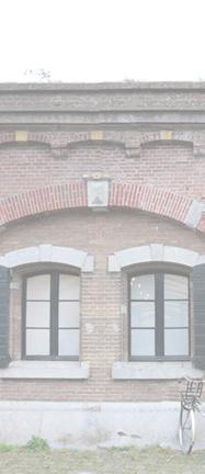
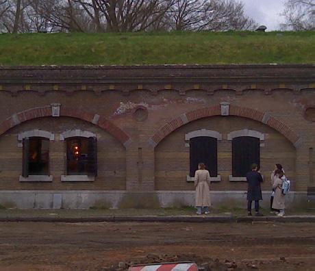
Retrofitting with Textiles: an innovative approach to façade challenges
- Giulia Procaccini
Academic Article
i-Mesh: material networks, light textures and Soft Architecture
-Luciano Ambrosini, Alberto Fiorenzi, i-Mesh
Company Article
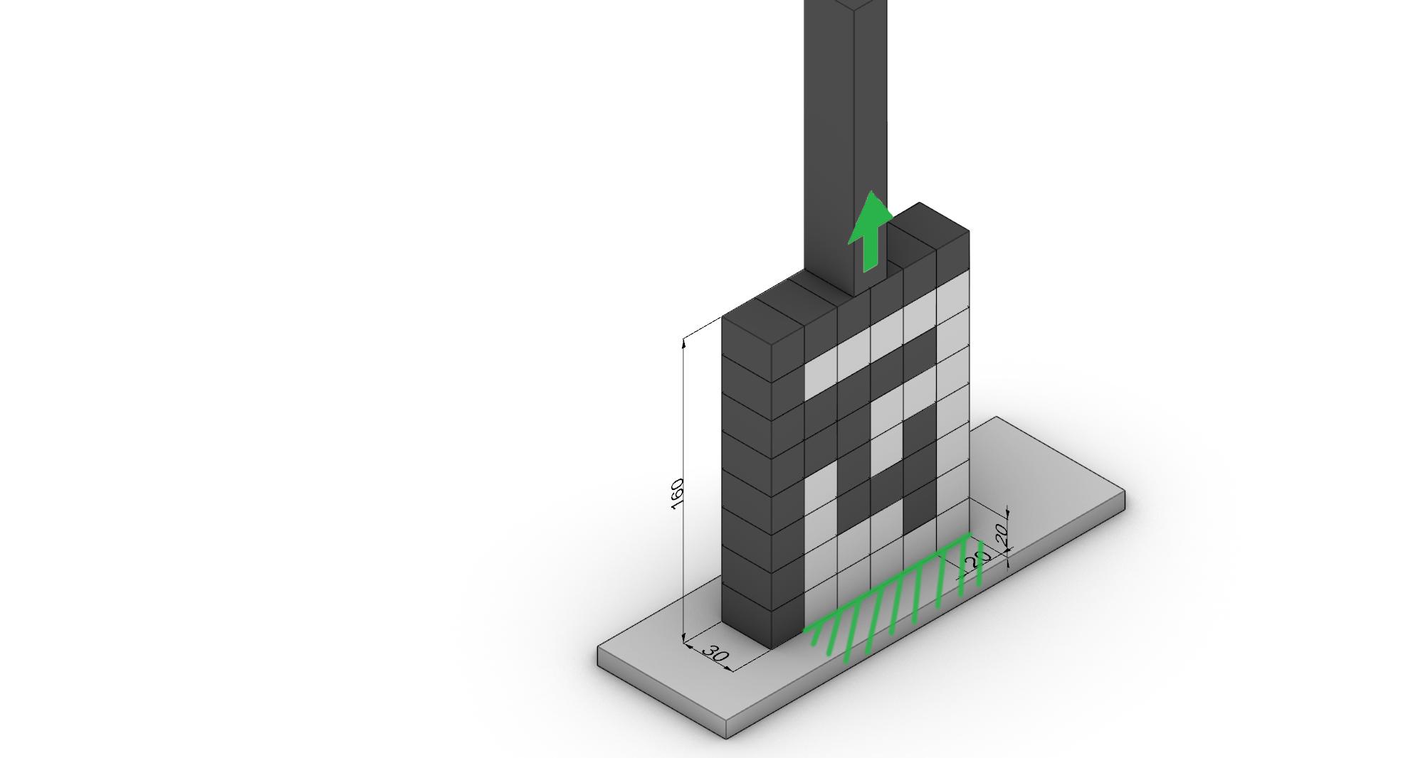
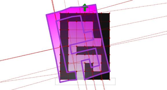
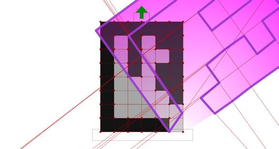
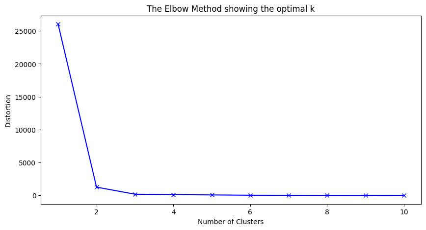
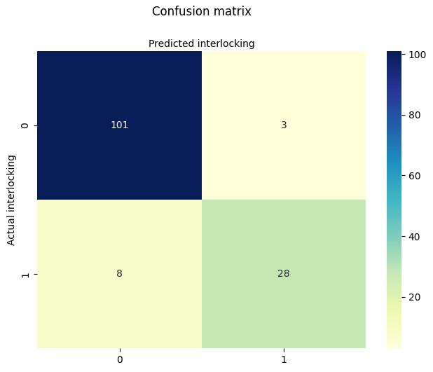
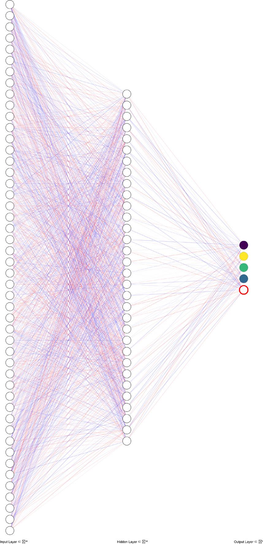
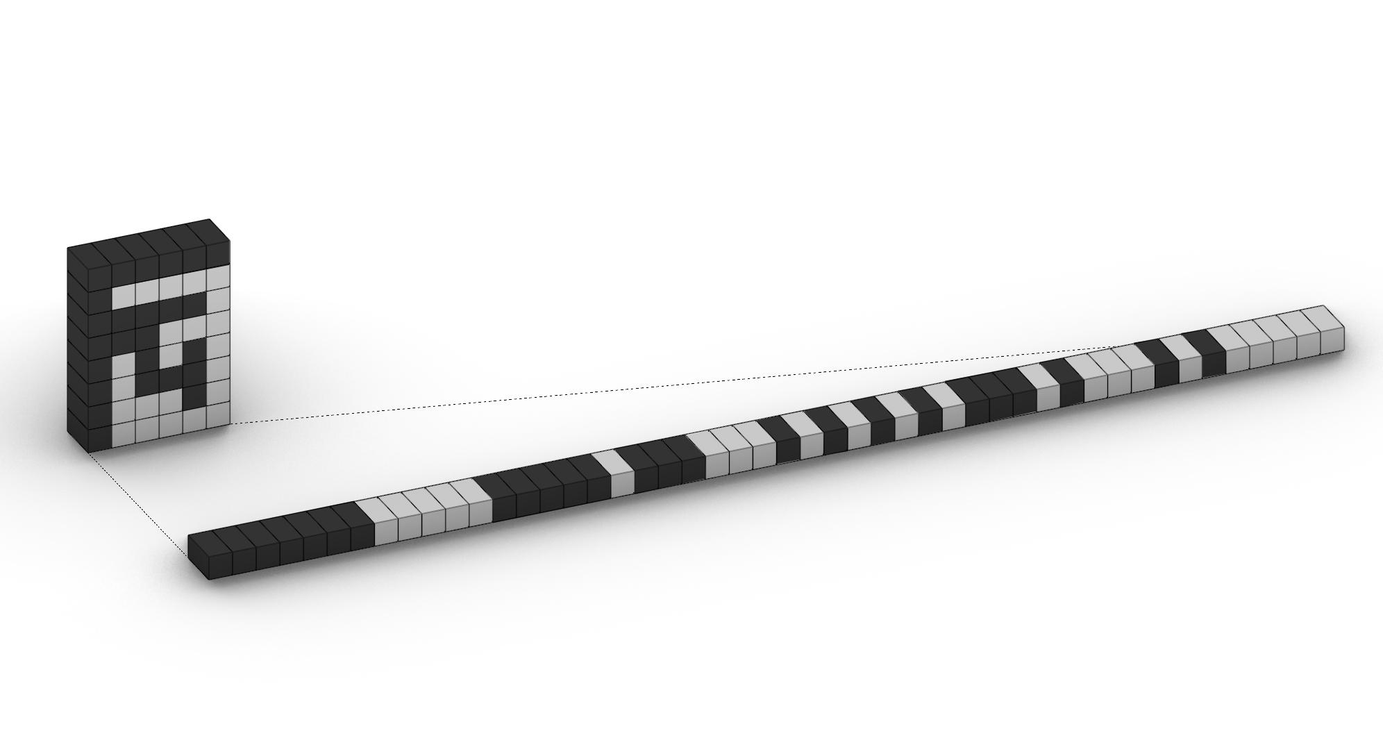
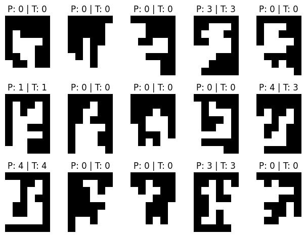
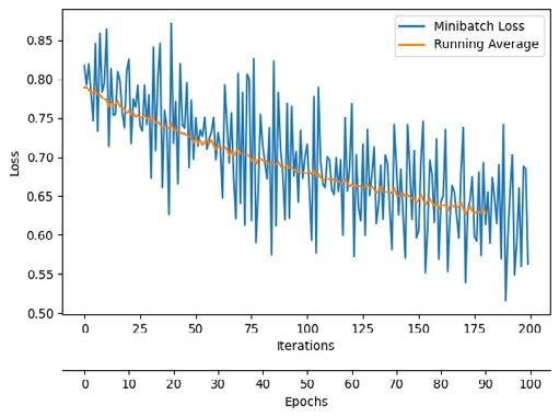
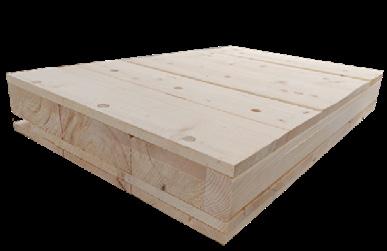
Interlocking Classification using ML - Sanguk Ryu
Computational Intelligence for Integrated Design - TU Delft
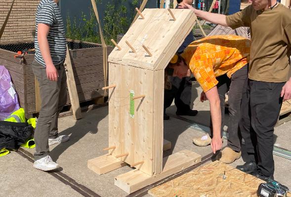
- Frederic de Milliano, Coco de Bok, Frank de Zwart, Beer van den Broek, Roan van K ammen
Circular Product Design - TU Delft
BT Spotlight article
Academic year Events Chart
- Praktijkvereniging BouT TU Delft
30th Board Signing in - Mauritz von K ardorff, BouT
Praktijkvereniging BouT 2024-25 TU Delft
EDITORIAL
Textiles in Architecture
In the evolving world of architecture, textiles are moving beyond their traditional roles to influence everything from building facades to energy efficiency. This shift has sparked a debate: 'Will textiles contribute to the future of sustainable architecture, or are they just a fleeting trend that sacrifices durability for novelty?' This edition explores the growing role of textiles, examining their historical roots, varied uses, and potential to reshape our built environment.
Critics argue that textiles lack the durability of traditional materials like stone or concrete, raising concerns about their longevity and resilience, especially in extreme weather. However, modern textiles like ETFE challenge these assumptions, offering durability, flexibility, and sustainability. Certain textiles also enhance energy efficiency, with possibilities like photovoltaic fibers for solar power.
While concerns about durability are valid, advancements in textile technology are addressing these issues, blending the strengths of textiles with traditional materials. Beyond their technical benefits, textiles add cultural and aesthetic value, infusing warmth and texture into modern designs. By embracing textiles, we can weave a future where innovation and tradition co-exist in harmony.
This edition marks the beginning of my journey as editorin-chief, and I want to congratulate the 2023-24 editorial team for their outstanding work on previous issues. I’m grateful to Ramya Kumaraswamy, our former editor-inchief, for trusting me with this role. I also warmly welcome the new members of this year’s Rumoer committee. As we celebrate 30 years as a student association, I’m excited about the special editions we have planned.
We hope you enjoy the 86th edition of Rumoer as much as we enjoyed curating it for you.
Swornava Guha Editor-in-chief
| Rumoer 2024-2025
Rumoer committee 2024-2025
Minoo Daniel Laila Ziyue
Swornava
Olivia Rossella
KNITCRETE
Innovations in fabric formwork using precision fabricated 3D knitted textiles
Dr. Mariana Popescu
Recent advancements in computational design tools have allowed architects and engineers to effortlessly explore complex geometries. Structures with intricate doubly curved geometries are increasingly designed and constructed based on different design logics. These shapes can result from architectural expression characterized by advancements in digital modelling, a fascination with curves, and a shift towards mass customization instead of mass production. Simultaneously, computer numerically controlled (CNC) machinery and the rise of digital fabrication techniques have simplified and expedited their fabrication, creating the illusion that any conceivable shape can be realised. Without considering structural performance, these designs require costly and material - intensive structural QR1: website
solutions. Therefore, considering structural principles in design is key to reducing the negative impact of construction on the environment.
Informed Design
In contrast to freeform geometries motivated by individual creativity, designing structures that integrate structural performance within architectural geometry results in aesthetically pleasing, economical, and material-efficient systems. Form-found geometries, driven by structural optimization for lightweight construction, rely on precise material placement and geometry to achieve stiffness and reduce material use. For their stiffness, structures with less material must rely on geometry and the placement of material strictly where needed according to, for example, the natural flow of forces. These principles have been used by structural engineers and architects throughout the 20th century. Notable examples include the filigree curved shells of Heinz Isler, Felix Candela or Eduardo Torroja that could effortlessly span large areas with little material. Similarly, Pier Luigi Nervi focused on building structures with the highest possible performance by working with material, geometry and prefabrication. He employed undulations, corrugations, and stiffening ribs to construct structures with large dimensions and high structural performance while reducing deadweight (Leslie, 2017; Halpern et al., 2013).
Flexible formworks
The expressive, intricate and curved geometries of structurally informed designs can be challenging to build using traditional construction methods relying on cut timber or milled formworks (Orr et al., 2011). Formwork for unique geometries is typically non-reusable, making
it a one-time product that ends up as waste, posing challenges in terms of both cost and sustainability. These custom constructions account for approximately one-half to as much as two-thirds of a structure’s cost (de Soto et al., 2018). To harness the full potential of non-standard and non-repetitive efficient structures, the formwork systems used for construction need to be rethought.
In traditional formwork systems, rigid and often heavy moulds are held in place by scaffolding, which needs foundations, and other temporary elements that make up a falsework. In contrast, fabric formwork is a construction technique that uses membranes as the main moulding material and can be a solution for building without the need for expensive, wasteful and time-consuming moulds. Instead of being propped up, textiles achieve the desired geometry by tensioning (with rigs, frames, external supports, bending active elements, cables, inflatables etc). The concept of fabric formwork in concrete construction dates to the late 1800s and early 1900s. Over time, fabric formworks have been adopted for various structural applications and can be found in a wide range of structures, including shells, floors, beams, columns, walls, foundations, and more (Veenendaal et al., 2018; Hawkins et al., 2016).
A recent development in fabric formworks, also referred to as KnitCrete, uses 3D knitted technical textiles as stay-in-place moulds for concrete structures (Popescu, 2019). Knitted textiles can be tailored to doubly curved and spatially complex 3D shapes, making it possible to integrate features and very specific (local) properties without the need for glueing, welding or stitching several parts together. In the case of KnitCrete, the knitted
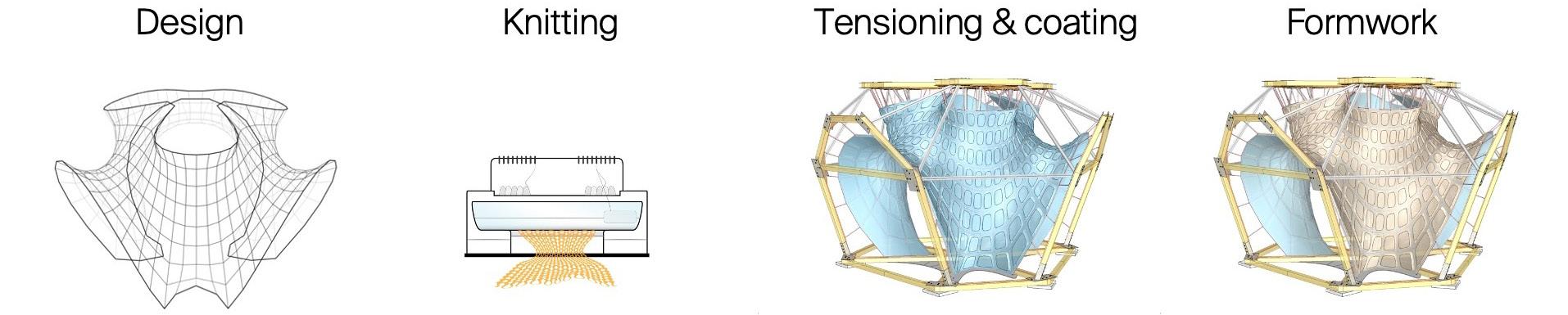
textile is prefabricated in a controlled environment (using existing industrial knitting machines) including all the needed features and having accurate placement of material according to an informed design. The produced fabric is foldable, easy to pack, and transport to the work site, where it is tensioned into shape. Together with the minimal frame and scaffolding, the textile now creates a formwork system for the concrete or any other structural material to be cast (Figure 2).
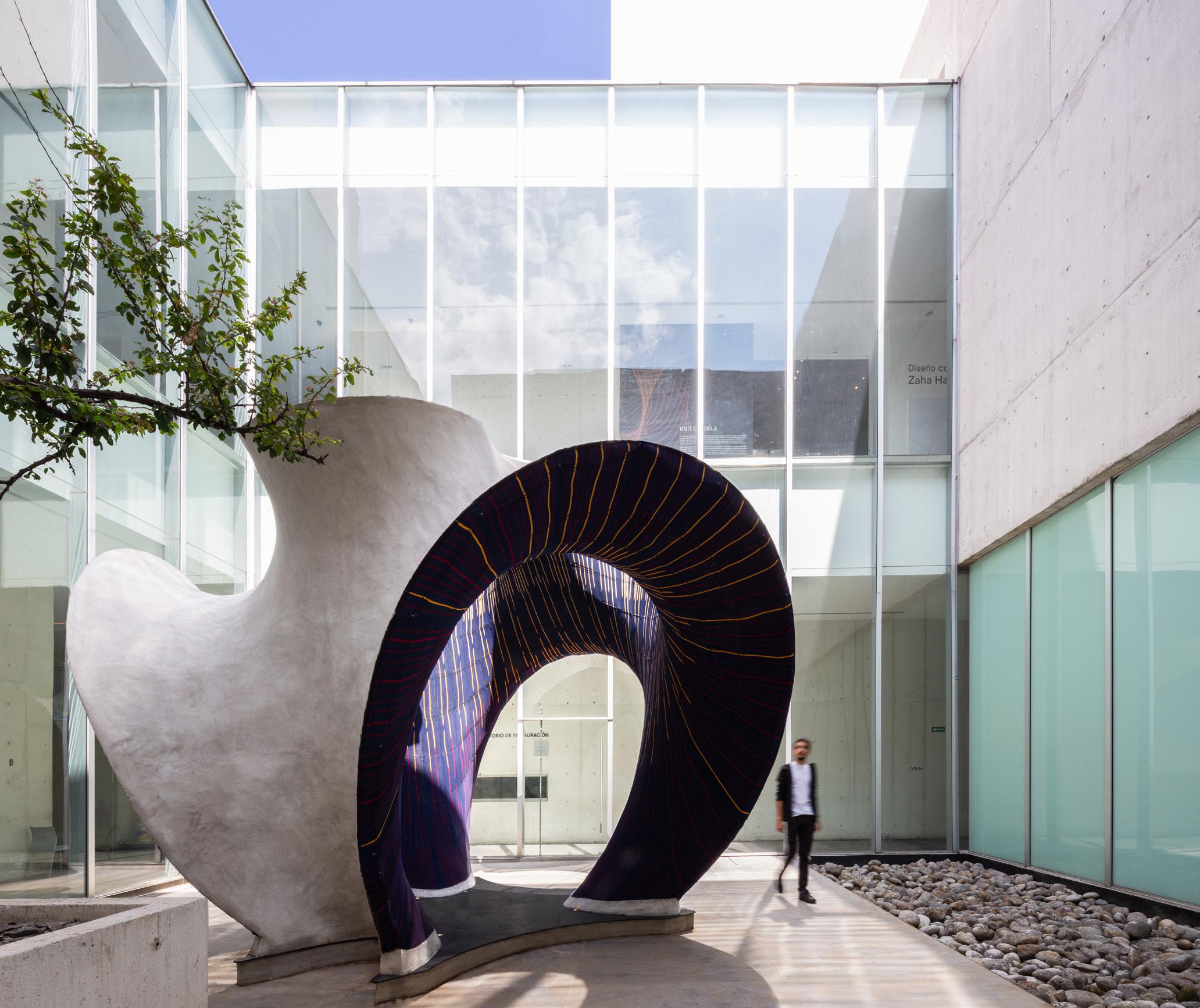
KnitCandela - Challenging construction
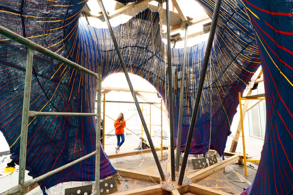
KnitCandela is the first architectural-scale prototype built using this method (Popescu et al, 2021). Designed as a homage to Spanish-Mexican shell builder Félix Candela (1910-1997), the shell's curved geometry is reminiscent of Candela's restaurant in Xochimilco. It is a thin, freeform concrete waffle shell built using a custom prefabricated knitted textile as shuttering and a form-found cable net as the main load-bearing formwork. The shell was built at the Museo Universitario Arte Contemporáneo (MUAC) in Mexico City as part of the first Zaha Hadid Architects exhibition in Latin America, on display from October 2018 to March 2019 (Figure 5).
Weighing 55kg, the 50m² formwork was easy and compact to transport to the site. It was tensioned in a
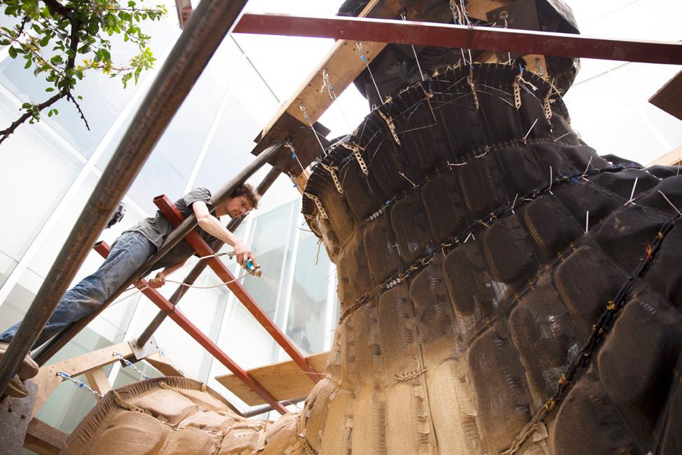
timber and steel rig (Figure 3) and coated with a fast-setting cement paste (Figure 4). The digitally designed and fabricated textile provided integrated features for inserting and guiding elements such as cables and inflatables that shaped the sophisticated mould. Fibre-reinforced concrete was manually applied onto the formwork to create a 3cm-thick shell with
4cm-high rib stiffeners. Cavities within the formwork were formed by inflating standard modelling balloons in pockets within the textile, coating the top layer of the textile with fast-setting cement paste, and casting concrete onto the stiffened textile. Once the concrete hardened, the pockets were deflated, leaving the textile in place and visible on the inside of the structure. The weft-knitted textile not only guided the cables and kept the inflatables in position but also controlled the size and degree of inflation. Because the pockets and textile properties controlled the size and inflation, standard balloons could be used for all cavities. This meant custom solutions could be created with standard elements.
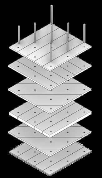
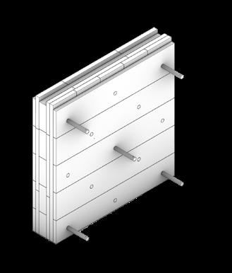
KnitNervi - Integrated structure and formwork
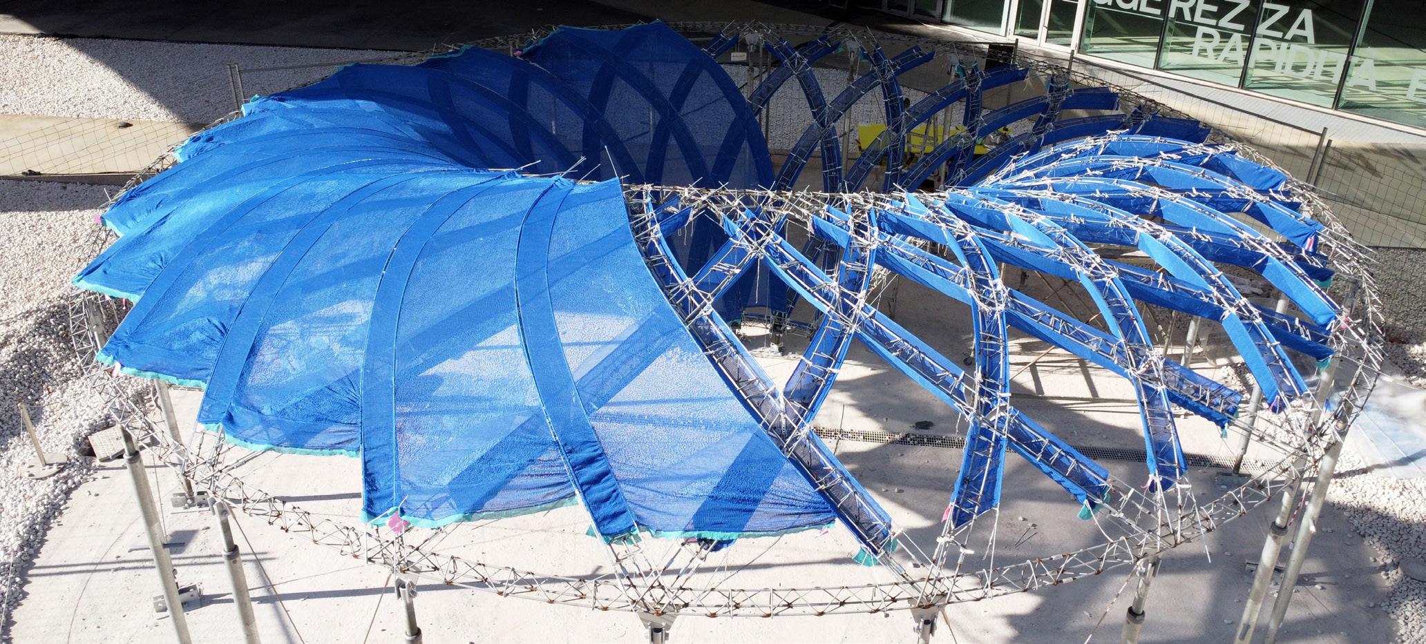
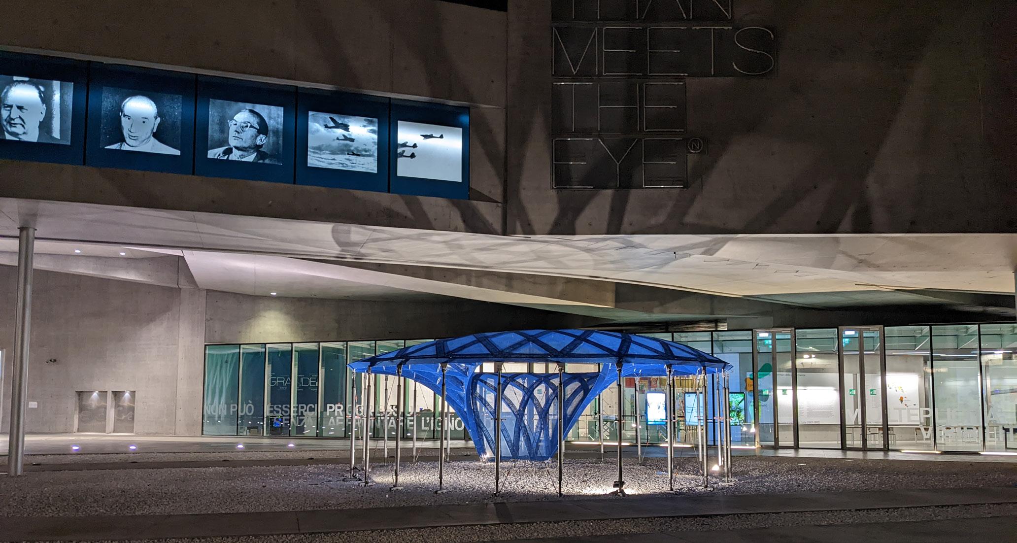
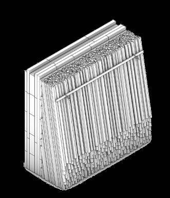
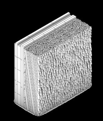
The KnitNervi (Figure 1) prototype pays homage to the work of P.L. Nervi and his pioneering approaches to
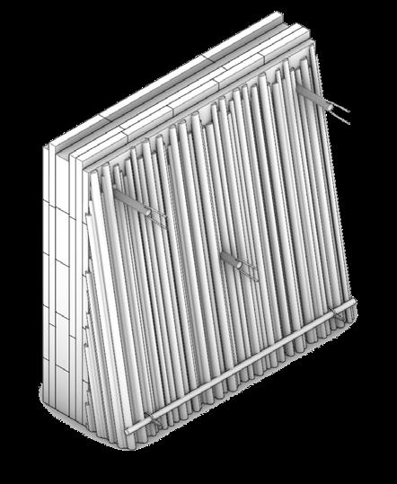
engineering design and construction (Popescu et al., 2024). Built for the “Technoscape: The Architecture of Engineering” exhibition at the MAXXI Museum in Rome, Italy (Ciorra and Casciato, 2022), it reimagines the compression-only dome structure of the Palazzetto dello Sport as a funnel-shaped concrete skeleton with a droplet-shaped central support. The prototype showcases an integrated flexible formwork system with a bending-active falsework and 3D knitted shuttering.
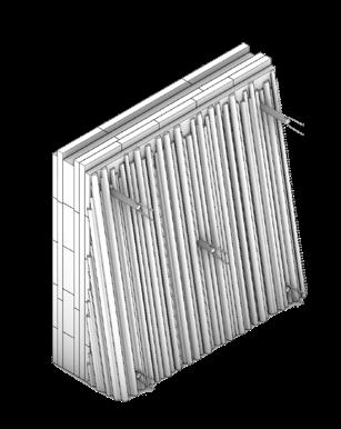
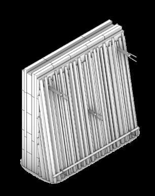
The double-layered gridshell structure is created by elastically bending slender straight rebars into a diagrid of rebar cages. Its curved geometry provides sufficient stiffness while supporting the textile shuttering, designed to ultimately remain in place as reinforcement for the concrete ribs. This strategy eliminates the need for falsework. The knitted textile shuttering is then tensioned
into shape at the desired distance between shuttering and reinforcement using a simple custom 3D-printed spacer fitted onto the rebar cage (Figure 6).
The textile’s texture, density, and overall loop-level (see section below) architecture were designed with a hierarchy of functions. The rib sections, which serve as formwork for casting concrete, have a denser texture, while the interstitial surfaces not used for casting were designed with a pattern of varying local densities.
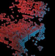
Due to the temporary nature of the installation, concrete was not cast into the diagrid rib structure. Consequently,
the focus of the demonstrator was on further developing a formwork system using 3D knitted textiles that is deployed using elastic bending to reduce the amount of needed supports and waste during construction. This approach also integrates controlled knitting detailing for both fabrication and construction. Not having cast concrete allowed non-specialist visitors of the exhibition to see how structures are built up with a translucent textile, offering an "x-ray through the structure" effect (Figure 7).
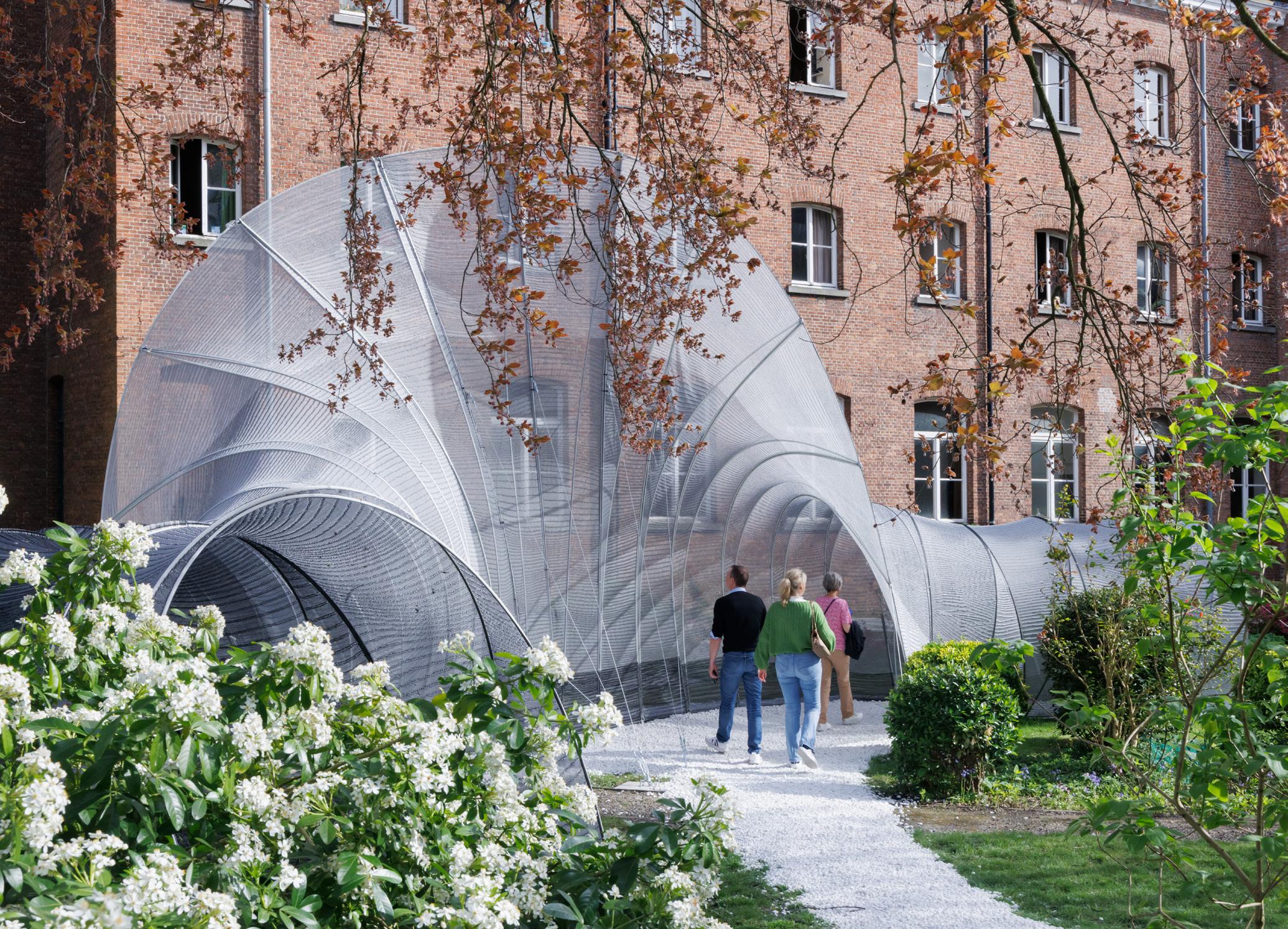
Common Thread - large scale control
One of the powerful aspects of using 3D knitting is
the ability to locally tailor material properties to meet specific mechanical and aesthetic requirements. This is possible due to the automated fabrication process used to manufacture these textiles. To produce a 3D knitted textile, an industrial machine uses an array of needles that perform various operations, forming loops. These loops form the basis of any knitted textile and, for the structures
discussed in this article, they are approximately 3mm x 5mm in size on average. This allows for relatively fine resolution in terms of both geometry and properties.
To guide the knitting machine during production, a knitting pattern is needed, which represents each loop to be formed. These instructions can be understood
as a grid of pixels with rows and courses, where each pixel represents a loop. Skilled technicians generally compose the knitting patterns, knowing where to place each instruction. Within an architectural context, creating these instructions manually would be an insurmountable bottleneck. Therefore, a crucial element for applying the flexible formworks described above is a developed computational pipeline that reliably translates a given 3D geometry into instructions for the knitting machine. This pipeline is used in all described prototypes and addresses questions of scale.
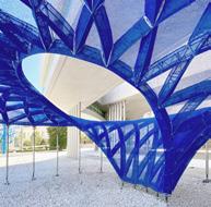
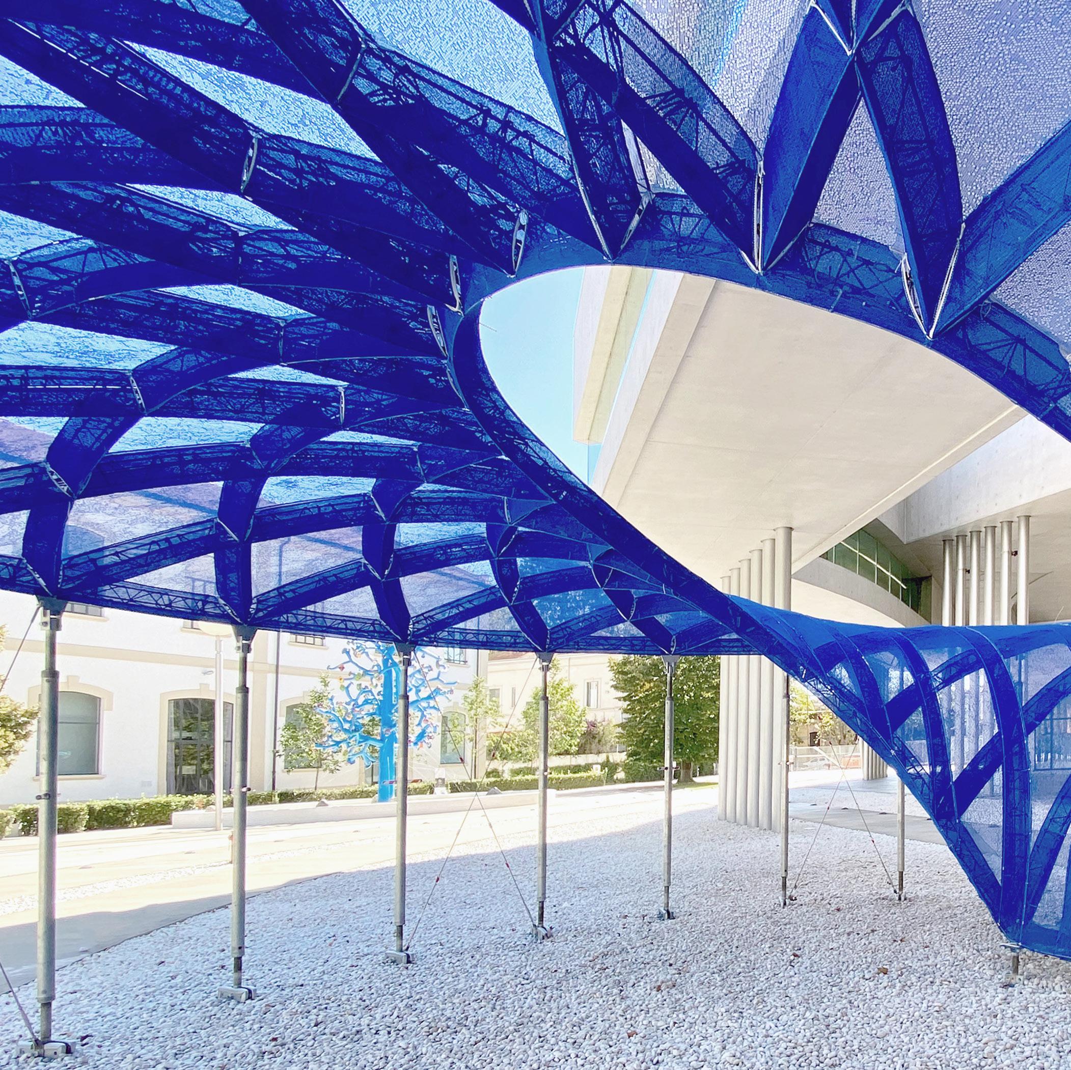
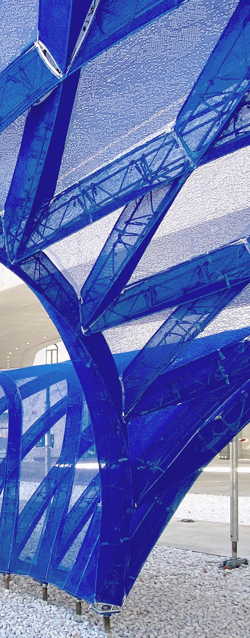
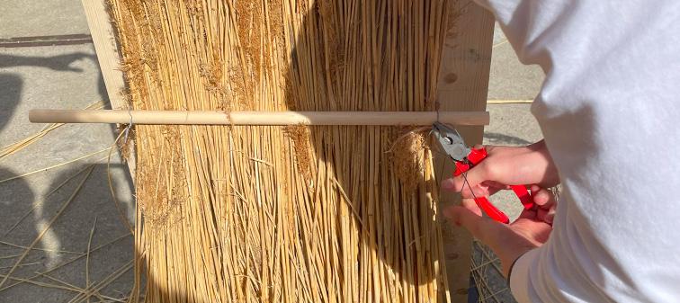
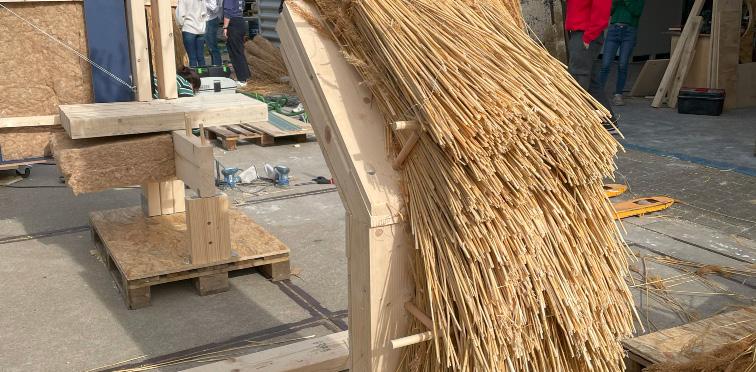
While scaling a technology to work from small-scale prototypes to architectural scale and increasing the produced area, the computational pipeline also needs to be scaled to generate larger geometries quickly and with increased resolution control. A good example of this scaling is the Common Thread (Figure 8) pavilion built for the 2024 Brugge Triennale (Spaces of Possibility). The structure is an ephemeral, flexible structure based on a
bending-active framework with a knitted textile made of recycled PET yarns. It features 300 square meters of knitted surface area with a controlled surface texture that required patterns to be generated on a 2x2 loop grid.
References
Casciato M. and Ciorra P., 2023 “Technoscape.The Architecture of Engineers”, 1, Forma Edizioni, Rome, Italy
García de Soto, B., Agustí-Juan, I., Hunhevicz, J., Joss, S., Graser, K ., Habert, G. and Adey, B. T. (2018), ‘Productivity of digital fabrication in construction: Cost and time analysis of a robotically built wall’, Automation in Construction 92(December 2017), 297–311.
Halpern, A. B., Billington, D. P. and Adriaenssens, S. (2013), ‘The ribbed floor slab systems of pier luigi nervi’, Journal of the International Association for Shell and Spatial Structures 54(176-177), 127–136.
Hawkins, W. J., Herrmann, M., Ibell, T. J., romoser, B., Michaelski, A., Orr, J. J., Pedreschi, R., Pronk, A., Schipper, H. R., Shepherd, P., Veenendaal, D., Wansdronk, R. and West, M. (2016), ‘Flexible formwork technologies – a state of the art review’, Structural Concrete 17(6), 911–935
Leslie, T. (2017), Beauty’s Rigor: Patterns of Production in the Work of Pier Luigi Nervi, University of Illinois Press. Orr, J.J., Darby, A.P., Ibell, T.J., Evernden, M.C. and Otlet, M., 2011. Concrete structures using fabric formwork. The Structural Engineer, 89(8), pp.20-26.
Popescu, M.A., 2019. nitCrete: Stay-in-place knitted formworks for complex concrete structures (Doctoral dissertation, ETH Zurich).
Popescu M., Rippmann M., Liew A., Reiter L., Flatt R.J., Van Mele T. and Block P. 2021. “Structural design, digital fabrication and construction of the cable-net and knitted formwork of the K nitCandela concrete shell”, Structures, 31: 1287-1299
Popescu M., Christidi N., Scheder-Bieschin L., Bodea S., Van Mele T. and Block P.K nitNervi: Lightness and tailored materiality for flexible concrete construction, FABRICATE 2024, M. Ramsgaard Thomsen and P. Ayres (editors),: 230-239,UCL PressCopenhagen,2024.
Veenendaal, D., West, M., and Block, P. “History and overview of fabric formwork: using fabrics for concrete casting”. In: Structural Concrete 12.3 (2011), pp. 164–177.
Dr. Mariana Popescu under 35”. She is currently Assistant Professor for Digital fabrication in the Civil Engineering and Geosciences Faculty of TU Delft.
Mariana Popescu is a computational architect and structural designer with a strong interest and experience in innovative ways of approaching the fabrication process and use of materials in construction. Her area of expertise is computational and parametric design with a focus on digital fabrication and sustainable design. Her extensive involvement in projects related to promoting sustainability has led to a multilateral development of skills, which combine the fields of architecture, engineering, computational design and digital fabrication. In 2019, she successfully defended her Ph.D. and was named a “Pioneer” on the MIT Technology review global list of “35 innovators
KOMATSU SEIREN FABRIC LABORATORY: "fa-bo"
Kengo Kuma and Associates
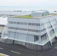
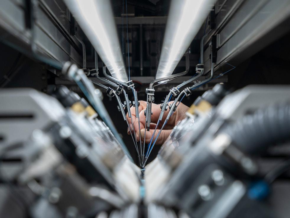
The potential of using carbon fiber for earthquake resistance: Komatsu Seiren Fabric Laboratory
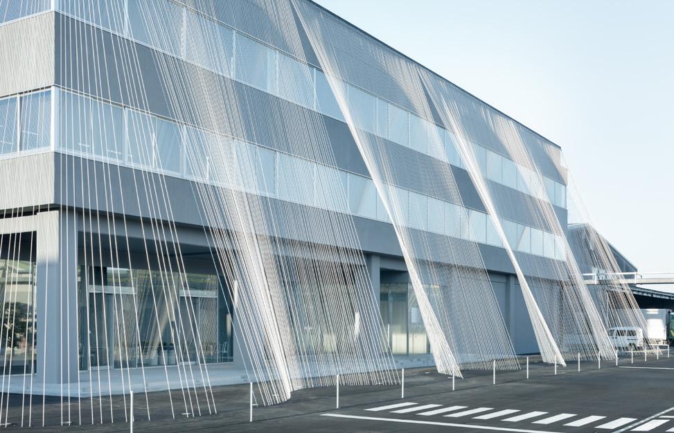
This renovation project focuses on the head office building of Komatsu Matere, formerly Komatsu Seiren brand. Originally RC (reinforced concrete) frame construction, the building upgraded using carbon fiber enhancements for earthquake resistance. The interior transformed into a museum called “fa-bo” (fabric laboratory) showcasing cutting-edge technology and innovations developed by the company.
A remarkable material, carbon fiber, weighing less than a quarter of steel, boasts tensile strength ten times greater.
Highly resistant to rust, chemicals and heat, carbon fiber is an ideal choice for extensive structural applications. Japanese architecture practice employs carbon fiber reinforced plastic (CFRP) sheets, primarily used for repairing RC structures. Prior to “fa-bo” design process, carbon fiber use was quite limited with rods being legally restrictive. Beyond this carbon fiber repair application, its full potential could not be achieved through wider adoption without this case study to substantiate rods’ immense contribution.
The development of the carbon fiber rods
Komatsu Seiren, leading pioneer in the textile processing and dying industry, developed the CABKOMATM Strand Rod with proprietary techniques. Uniformly impregnating core carbon fibers with thermoplastic resin results in a product that not only easily thermoform and process, but also possesses compressive properties. Carbon fiber has been known for its tensile strength rather than its shear resistance. In response to this CABKOMATM Strand Rod implements a slight twist in the fiber bundles, inspired by the historic Japanese technique “kumi-himo”. Significantly improving the bending strength, multiple threads are braided into a robust, single cord. The marriage of these techniques results in adaptable construction material, suitable for a wide range of applications.
Impressively only 9mm in diameter, CABKOMATM Strand
Rod offers a delicate option for seismic reinforcement compared to traditional D19 steel rebar, of similar strength. Notably, the rods can be stored at ambient temperatures and the off-cut scraps are recyclable for an environmentally sustainable and cost-effective material.
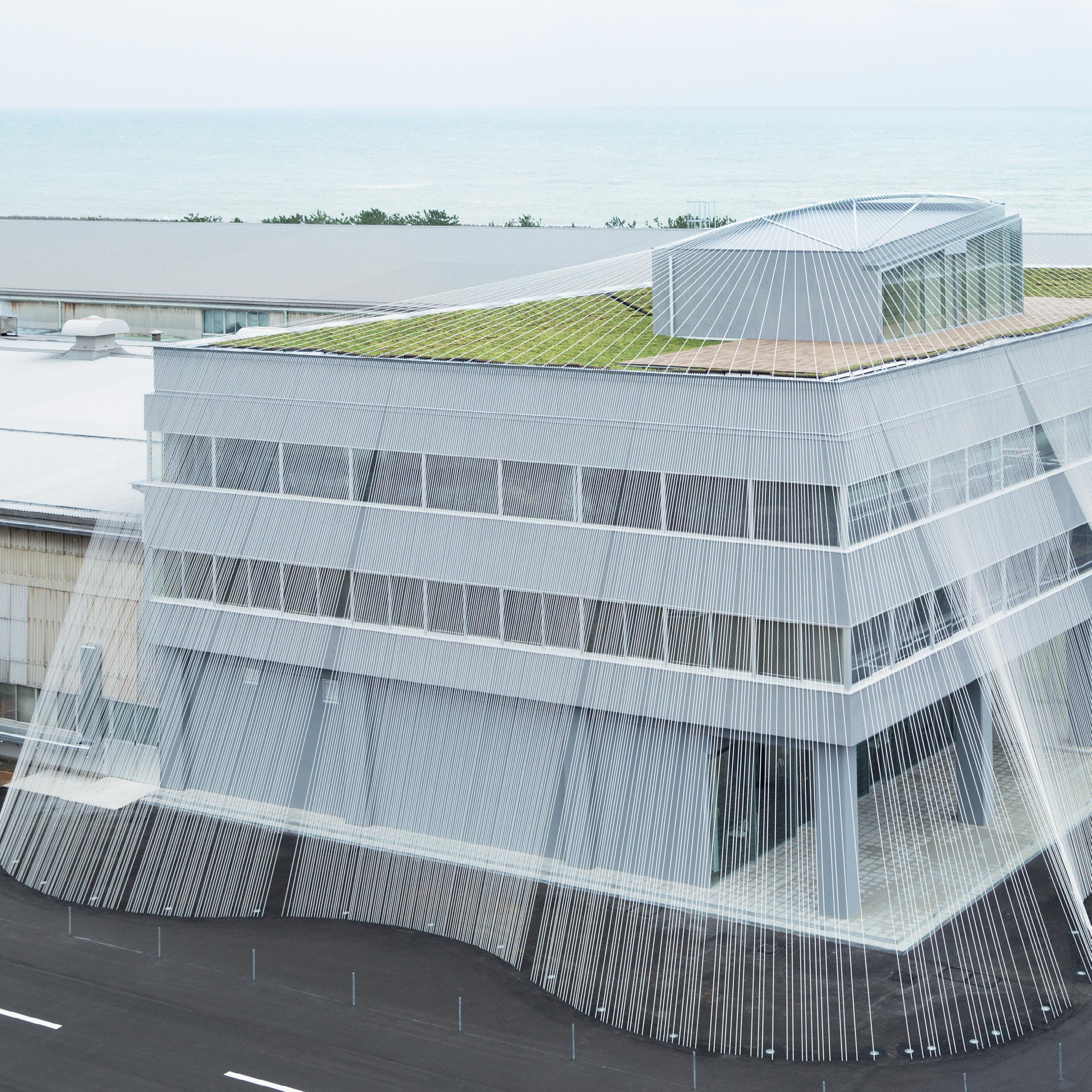
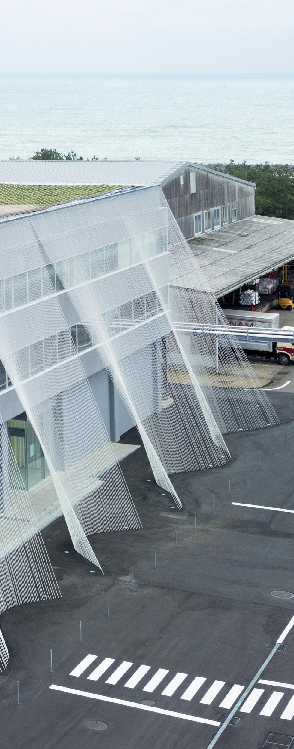
Exterior and Interior use of CABKOMATM
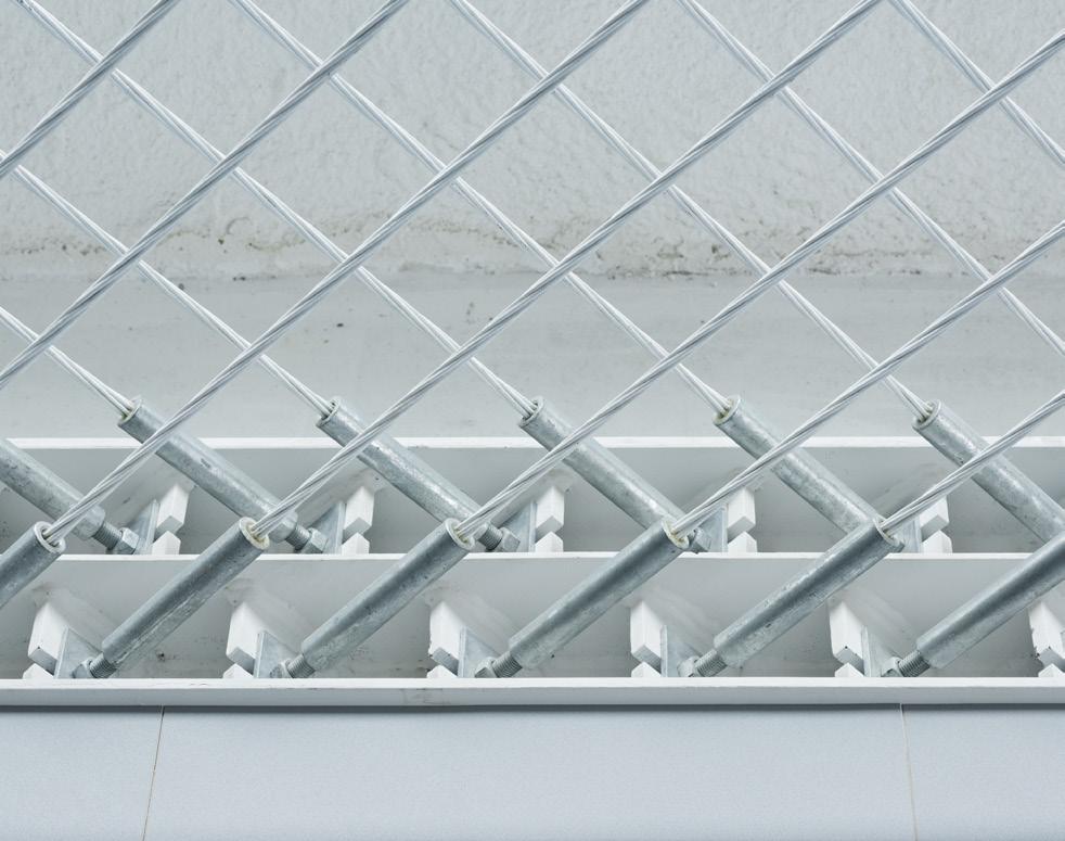
Carbon fiber creates an organic drape across fa-bo’s exterior, visually connecting the building to the ground. Not only serving as a striking façade, reflecting the textile company heritage, but also pioneers entirely new form in structural reinforcement. During earthquakes, rods
oriented in opposite directions help suppressing tensile deformation, providing both aesthetic and structural benefits. Across the building façade, draping imparts an elegant, lace-like appearance, nightly illuminated, fibers resemble the aurora borealis, a shimmering, fantastic quality.
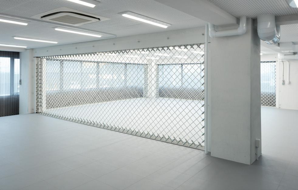
Connecting the penthouse and parapet, a seamless integration of carbon fiber elements blend to the building’s envelope. Creating the effect of being wrapped in delicate, soft fabric, the entire building benefits from this visual and functional aspects of the architecture. Reminiscent of delicate bamboo work, the interior features carbon fiber bracing. These numerous wires create a “transparent earthquake resistant wall”, seismic strengthening implemented to preserve open views and maintain an airy interior atmosphere.
Additional sustainability considerations Reducing the CO2 emissions by being lightweight,
CABKOMATM Strand Rods can be rolled up and bundled for a low energy transport by hand, not relying on heavy machinery during install. The use of carbon fiber, compared to steel of similar strength, represents a more environmentally friendly approach to construction.
Greenbiz, a porous ceramic material made from surplus biomass cake produced as byproduct of the dyeing process, adorns the rooftop garden. The unique porous structure of greenbiz offers lightweight yet high water retention properties, this in turn enhances the roofs insulation and durability. By using greenbiz, a lighter, thinner planting structure, compared to conventional systems, emphasizes the project’s commitment to sustainability.
THE MUSEUM DESIGN AND CONCEPT
Innovative use of textile materials
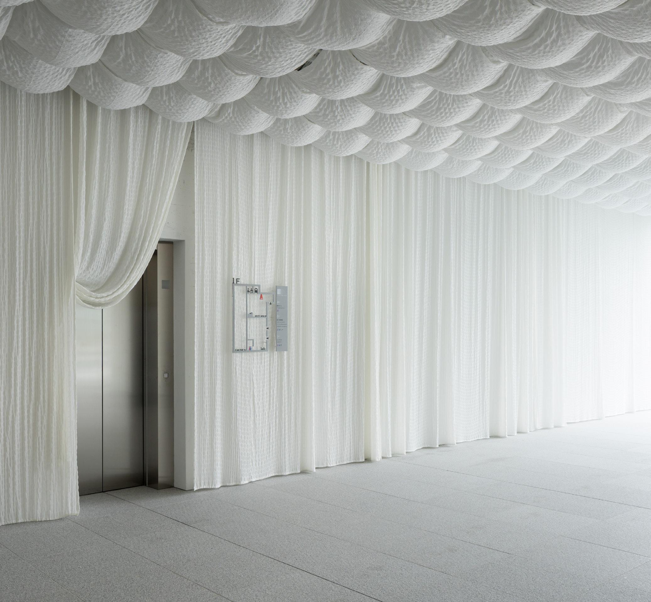
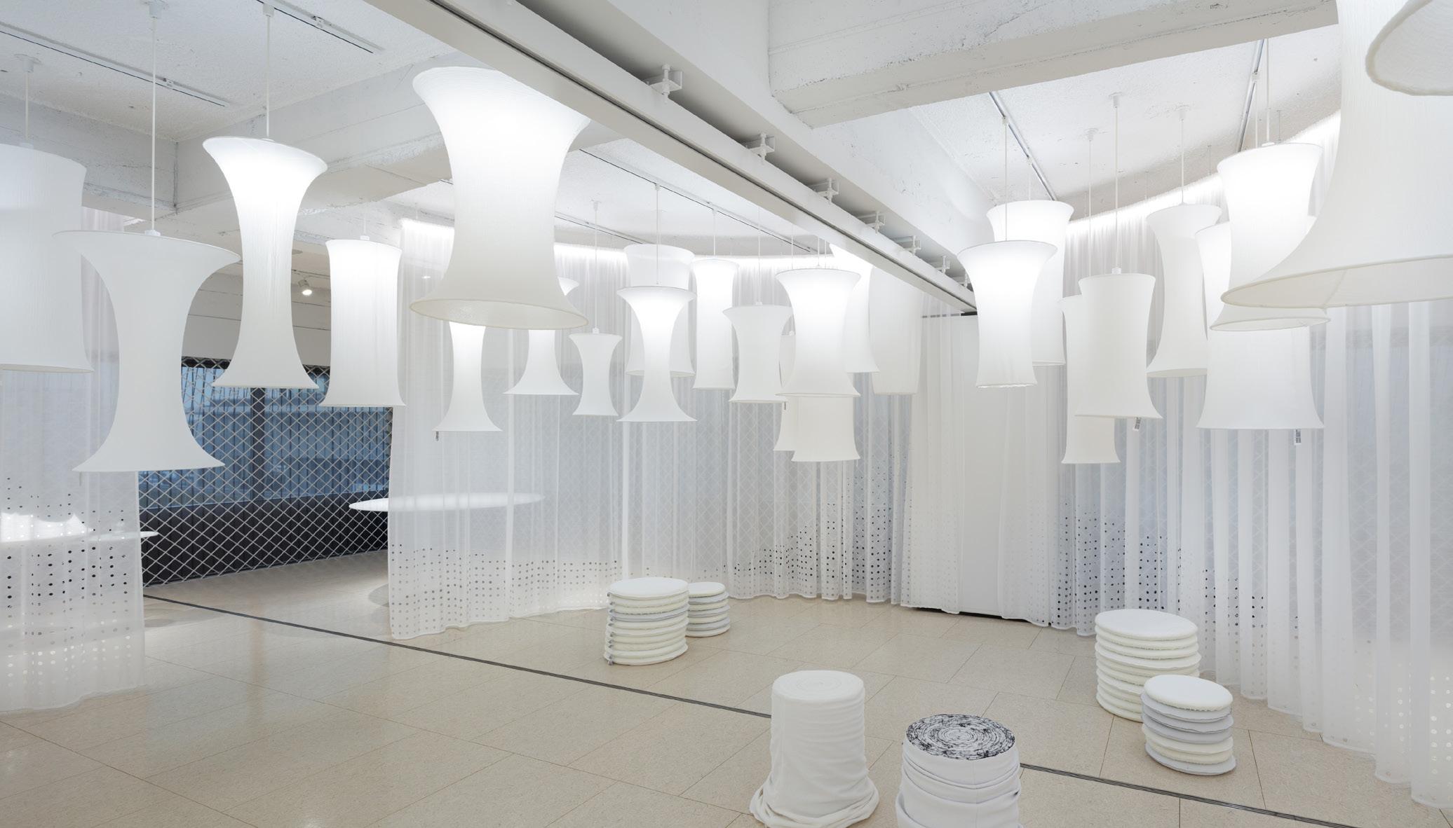
The museum is designed to showcase innovative uses of textile materials in architectural spaces, providing various examples of how these materials can be integrated into modern design. Komatsu Seiren’s advanced processing technology is used to create fabrics with diverse textures for the interior design, including curtains that partition exhibition spaces and soft fabrics adorning the walls and ceiling of the entrance hall. Pleated tubular fabrics are used for balloon lighting and air conditioning ducts, allowing both light and air conditioning to permeate through the fibers. This approach thoroughly integrates fiber technology not only into the building frame but also into its facilities, thus thoroughly “fiberizing” the entire building.
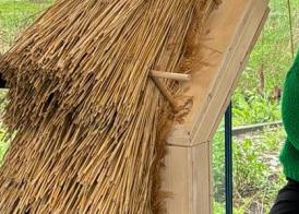
The project highlights how incorporating textile industry expertise into architecture can provide insights for achieving a sustainable society. Primitive houses were made by weaving soft materials together, wherein the repetitive act of weaving brings individual strands together to form a strong whole. The concept of fa-bo’s seismic reinforcement, which increases strength through repetitive details, aligns with this structure inherent to fabric. This method provides a unique form of strength, distinct from that of traditional steel or RC structures.
The flexibility of this type of carbon fiber complements softer materials like wood, enhancing structural integrity without sacrificing the material's natural qualities. Unlike the limited applications of heavy steel, carbon fiber’s versatility allows it to be used in a wide range of products, from furniture to large-scale civil engineering projects.
We are convinced that the future of building materials will transition from the current era of rigid architecture using environmentally taxing steel and concrete to an era characterized by flexible architecture utilizing ecofriendly, lightweight, and soft materials. The "weaving of architecture" with these innovative materials will not only enable the construction of more environmentally sustainable buildings but also allow for these structures to be "unraveled" and the materials reused once they have served their purpose.
Textiles possess several inherent structural qualities through their three-dimensional weave and fiber density. Strength: small individual fibers are woven together to form stronger expansive surfaces. Operability: being lightweight and foldable, textiles can easily be folded and transported. Functionality: by adjusting the weave’s density, textiles come to provide breathability and thermal insulation. Together, these properties are essential for adaptive future architectural designs aimed at reducing energy consumption and protecting occupants from harsh environmental conditions.
Light and transparent carbon fiber seismic reinforcement, as realized in this project, represents a paradigm shift, challenging traditional concepts of heavy and largescale seismic solutions. We believe its groundbreaking nature can change how we think and approach building design itself. Influenced by textile technology, the future of architecture is set to become lighter and more flexible.
Kengo Kuma was born in 1954. He established Kengo Kuma & Associates in 1990. He is currently a University Professor and Professor Emeritus at the University of Tokyo after teaching at Keio University and the University of Tokyo. KKAA projects are currently underway in more than 50 countries.
Kengo Kuma proposes architecture that opens up new relationships between nature, technology, and human beings.
His major publications include Kengo Kuma Onomatopoeia Architecture Grounding (X-Knowledge), Nihon no Kenchiku (Architecture of Japan, Iwanami Shoten), Kengo Kuma
Zen Shigoto (Kengo Kuma – the complete works, Daiwa Shobo), Ten Sen Men (Point Line Plane, Iwanami Shoten), Makeru Kenchiku (Architecture of Defeat, Iwanami Shoten), Shizen na Kenchiku (Natural Architecture, Iwanami Shinsho), Chiisana Kenchiku (Small Architecture, Iwanami Shinsho) and many others.
Combining glass with textiles - why Glass is known for its durability and high compressive strength, making it an excellent choice for both architectural and structural applications. Currently, only float glass is used in structural applications, which due to its flat nature, results in primarily two-dimensional façades and building envelopes. However, there's a growing trend towards fluid, freeform architecture, with several examples of curved glass surfaces aiming to achieve three-dimensional results.
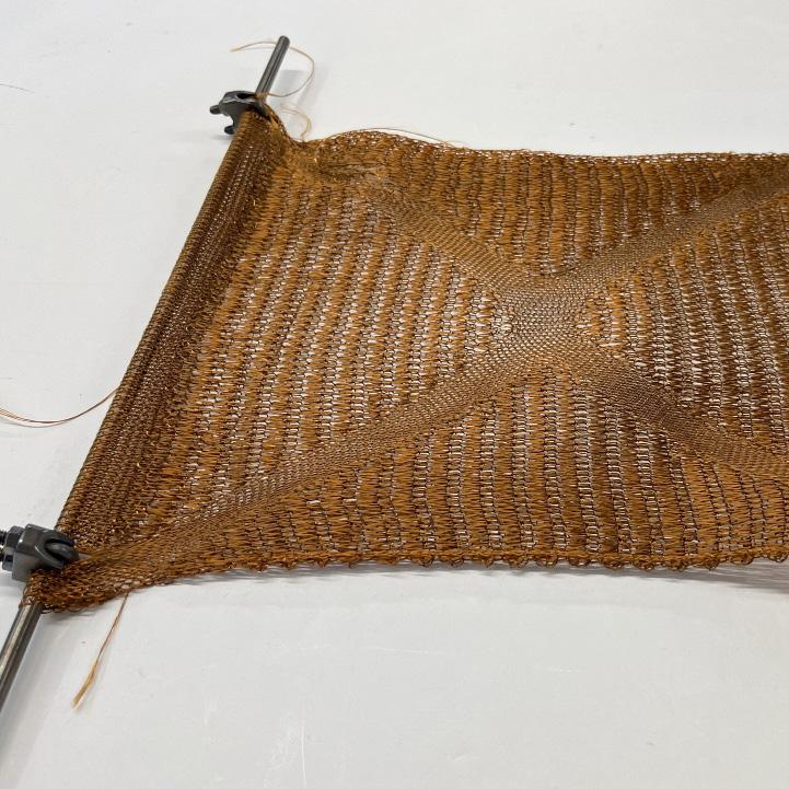
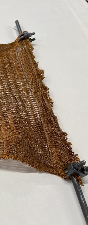
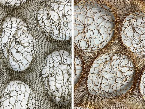
Fig. 1: CNC-knitted textile mould made of basalt. Mould after firing process in the glass oven
Most curved glass applications utilize curved float glass. Flat float glass can be shaped into the desired shape using various methods, which depend on factors like the required final strength, the curvature, the geometry to be achieved, and fabrication costs. Especially when heated, glass offers great geometric flexibility.
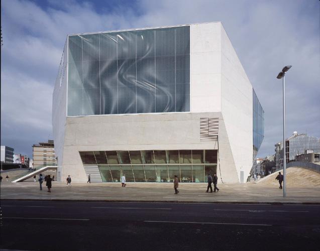
Curving float glass panels necessitates the use of moulds. Due to the expense of producing many different moulds for each unique panel of a freeform surface, curved glass is often standardized and repeated in a corrugated manner, as seen in projects like the Casa da Musica in Porto, the MAAS museum in Antwerp, or the Nordstrom flagship store in New York. This standardization leaves little room for freeform geometric possibilities.
In other materials, such as concrete, flexible moulds have been used to create complex geometries in an easy way. The development of knitted textile moulds has expanded the boundaries of achievable geometry while minimizing material use and labor, leading to more sustainable, lightweight structures with reduced manufacturing costs. Currently, there is no known technique for creating freeform non-standardized glass panels with extreme geometries without significantly increasing costs due to mould fabrication. However, combining flexible textile moulds with glass offers significant potential. Knitted textile moulds could revolutionize glass curving, allowing for highly customizable architectural elements such as façades.
Using textiles to curve glass – experimental work
As mentioned, using textiles to create complex curved glass shapes seems promising. Since this combination has never been tested before, it was necessary to check its feasibility through physical experimentation. A series of experiments was conducted at the lab of the Glass & Transparency Research Group at TU Delft, aiming to understand the possibilities and limitations of using knitted textile moulds for such a fabrication process.
Selecting the proper fiber for the textile moulds was crucial. Continuous basalt fiber was chosen for the moulds due to its ability to withstand high temperatures and its relatively more sustainable nature among other high temperature technical textile fibers.
Fig. 2: CNC-knitted textile mould made of basalt. Mould after firing process in the glass oven
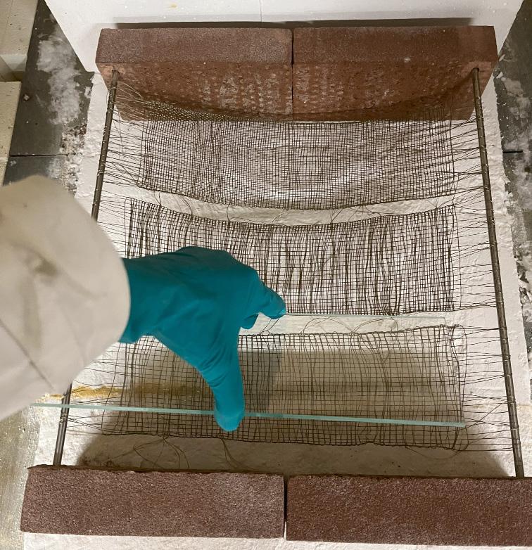
The experiments focused on geometry, surface quality, and redundancy. Various single and double-curved surfaces were created, and both hand-woven and CNCknitted moulds were tested. Hand-woven moulds were more rigid, while CNC-knitted moulds were flexible, allowing the glass to stretch and deform according to the knit pattern. It was observed that maximum glass deformation varied with thickness and knit pattern for knitted moulds, whereas hand-woven moulds produced curvatures based on their initial state, since the nature of the woven textile did not allow stretching of the mould.
geometries, though not as extreme as those possible with concrete formed on textile formworks.
Replicating double-curved surfaces was also successful. The repeatability of experiments showed nearly identical geometric results, even with previously used moulds.
Experiments also introduced multiple curvatures in the glass by coating the basalt mould to create a rigid shape or using textiles with multiple knit patterns. Both methods were successful. However, transitioning from negative to positive curvature to create complex shapes required additional support beyond textile draping. Using heat-resistant cement coating to produce rigid moulds successfully shaped glass into double - curved
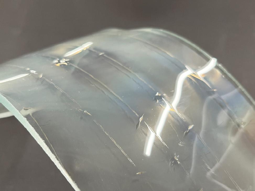
Regarding surface quality, direct contact between textile and glass or the use of coatings was tested. Without coating, the glass demolded easily but had a foggy surface due to crystallization. After inspecting all experimental results, it was concluded that optimizing the firing schedule could address the crystallization issue, and that it was not a matter of direct contact with the textile. Coated glass surfaces were almost transparent but not perfect, with the best results achieved using cement coatings.
Fig. 3: Single curved glass surface with direct contact with the basalt (without coating)
Fig. 4: Basalt mould before (left) and after (right) firing
An interesting result was that the textile gave a texture dimension on the formed glass surface. The texture imprinted by the mould varied with the density of the knitting pattern and the glass thickness, leaving marks of the mould’s support points. This textured glass could add aesthetic value to certain façade designs. Microscope examination revealed basalt inclusions in the glass surface, adding color hints without compromising glass integrity. Coatings prevented mould texture imprints but left light textures from the coating layer. Rigidifying coatings left inclusions of material deep in the glass matrix that could lead to microcracks, making them less ideal.
Finally, achieving redundancy for future glass panels was feasible. Simultaneous slumping of multiple glass pieces on a single mould resulted in perfectly aligned curvatures for both single and double-curved surfaces, allowing for potential lamination to meet façade panel strength
requirements.
Although still in its early stages, the use of knitted textile moulds to curve glass in freeform shapes shows great promise. These customizable moulds could significantly expand the possibilities of glass architecture without excessive manufacturing costs, leading to a new, enriched vocabulary of architectural design with glass.
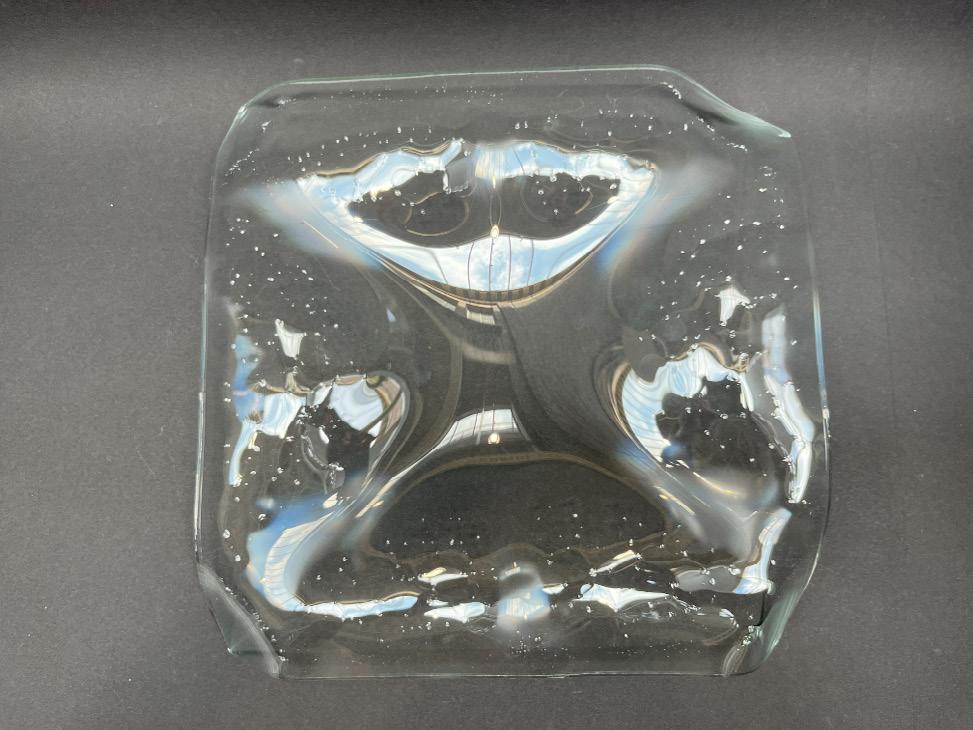
Fig. 5: Double curved glass shaped with textile mould rigidified with cement coating
Fig. 6: Vision for a freeform façade application
Anna is a recent graduate of the Building Technology MSc track within the Faculty of Architecture and the Built Environment at TU Delft. With a solid foundation in architecture, she holds a Diploma in Architectural Engineering from the National Technical University of Athens (N.T.U.A.) and is a licensed architect in Greece. Anna has extensive experience working as an architect on various projects, overseeing all stages from concept to construction with a strong emphasis on design. Prior to her master's program at TU Delft, she explored her creativity as a designer in the fashion industry, which sparked her
interest in textiles. During her master's studies, Anna focused on integrating the aesthetic values and design insights from her previous experiences with the technical knowledge of detailing and façade design.
Dipl. Arch. Eng., Ir. Anna Konstantopoulou
SUNTEX: Building climate resilient cities with solar textiles
Anna J. Wetzel
The world is warming. It is an evident and strong tangible effect of climate change. Cities in particular are hit hard by heat stress. Most of the world's population lives in urban areas and due to the Urban Heat Island effect (UHI), these areas are exposed to even higher temperatures. A systematic review of UHI studies using remote sensing data found that an increase ranging from 1 to 7 degrees can be suspected due to this phenomenon (Almeida et al. 2021). Increasing heat has a major impact on health, sleep quality, productivity and therefore also on the economy. Heat is already leading to additional deaths (The Lancet, 2021), especially among vulnerable groups.
Cities urgently need to be redesigned to remain healthy and vibrant places to live, work and meet in public spaces. To counter the effect of excessive heat trapped in buildings, concrete and infrastructure, sustainable climate adaptation strategies and interventions are
(studio Pauline van Dongen), Huub Visser (Tentech), Pauline van Dongen (studio Pauline van Dongen)
Fig. 1: Suntex opaque @ studio Pauline van Dongen
needed. Improving green infrastructure and bringing back parks, vegetation and bodies of water can cool down a city – however there’s not always the possibility to add those in a densely built environment. Moreover, growing large trees that provide the necessary shade can take ten to twenty years. Therefore complementary climate adaptive urban solutions need to be developed that can be applied in densely populated areas. In bustling cities, another major challenge is how they contribute to global warming. How can we stimulate
renewable energy in these busy areas? Within just a few decades we will have to rely entirely on renewable energy sources. Solar energy has become the cheapest electricity in history (IEA, 2020), making it a must for urban areas. However, the traditional silicon solar panels are one-size-fits-all, heavy and require specific structural support. This limits the places where they can be installed as well as the social acceptance of the technology. So we need more innovative ways to harness solar energy in the city.
Fig. 2: Temperature Difference Between Urban and Vegetated Land Due to Impervious Surface Area Credit: NASA Earth Observatory image by Joshua Stevens, using data from Bounoa, et al. (2015). Obtained
SUNTEX
Solving these complex and interconnected issues of energy transition and climate adaptation requires a multidisciplinary and holistic approach. This is where new materials and innovative design that blend energy production, ventilation, and shading come into play. SUNTEX is an innovative energy-generating textile invented by Pauline van Dongen and developed in collaboration with Tentech. The technical textile is woven with thin-film organic photovoltaics (OPV) and can be used as a building material. It is unique because of its double impact; as a shade textile, it provides cooling in the urban environment and at the same time generates solar energy. When used in shade structures and canopies, it can generate solar energy on large areas with many hours of sunshine, which currently remain unused due to a lack of suitable solutions. A case study of the Westraven building, the Rijkswaterstaat office in Utrecht, showed that if the current textile facade of the building would be replaced with SUNTEX, the lighting of the entire building could be supplied with power all year round (van Dongen et al. 2022).
SUNTEX can be used in the heat-resistant design of cities, where creating shade is the most effective way to lower the perceived temperature in public spaces. Shade cloth can reduce the perceived temperature with 9 up to 15 degrees Celsius (Spanjar et al. 2023). Flexible measures such as shade cloth are preferable to fixed measures such as the shade of arcades, because shade is only desirable for cooling in summer (van Heijningen et al. 2019). In addition to the degree of flexibility, deformability and light weight of Suntex, the variability of the material is unique. In contrast to standard solar technology, SUNTEX can 33
Fig. 3: Suntex opaque @ studio Pauline van Dongen
actually be designed. Besides the technical properties of the cloth, the material aesthetics such as transparency, colour and weave pattern can be adjusted to suit the application and context.
As a result, SUNTEX offers more diversity in the solar energy domain by giving designers and architects the opportunity to design with solar technology. This means that the technology will not only make a functional contribution, but can also be more embedded in our living environment and therefore in culture.
SUNTEX’ variability and flexibility
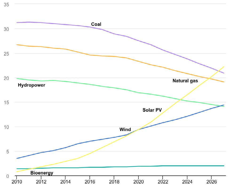
Fig. 4: Share of cumulative power capacity by technology, 2010-2027 Credit: Fossil fuel capacity from IEA (2022), World Energy Outlook 2022. Obtained from: https://www.iea.org/data-andstatistics/charts/share-of-cumulative-power-capacity-by-
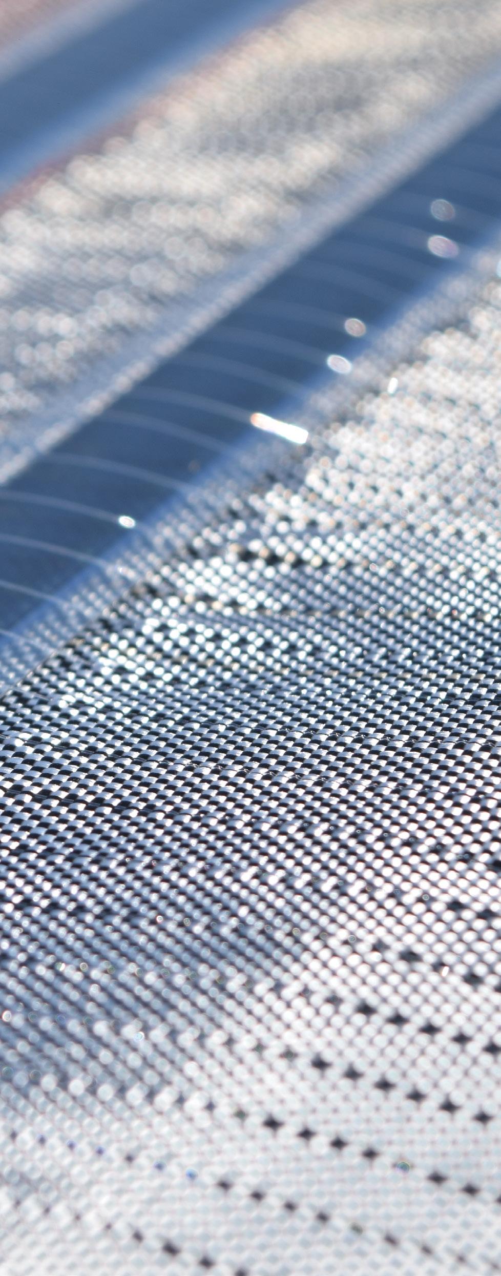
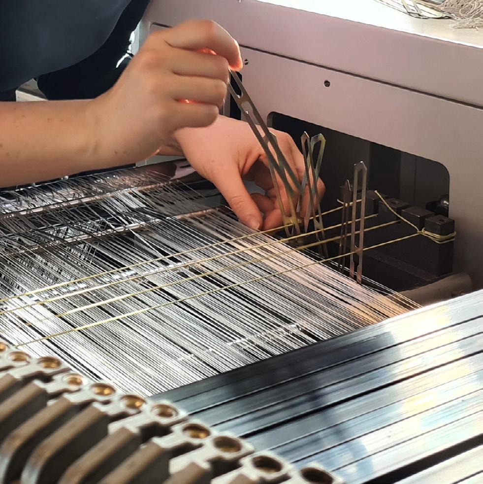
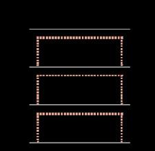
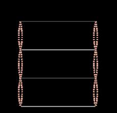
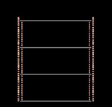
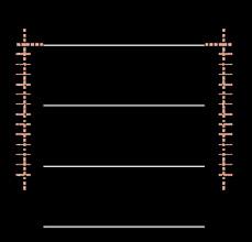
In contrast to the current one-size-fits-all design of silicon solar panels, SUNTEX can be adjusted for multiple purposes. Being a woven structure makes it possible to design, produce and match the properties of the textile to its functional and aesthetic use-case. While the general concept of transparent yarns holding the panel in place stays the same – the load-bearing fabric layer however can be adjusted. By choosing different yarn types, different properties can be created. For example, a very dense opaque weave can be made for a construction needing to bear high tensile loads. While an open mesh would be suited for see-through structures, such as a building facade. Previous testing has shown that the change in efficiency of the panels being held in place by transparent yarns is negligible and the overall fabric construction with tenacity and shearing angle allows for three-dimensional, double-curved surface constructions for architectural applications (van Dongen et al. 2023). Next to that, SUNTEX is lightweight (currently 500 grams per m²) and deployable, meaning that it can be easily folded or rolled up when being transported or stored.
SUNTEX Applications
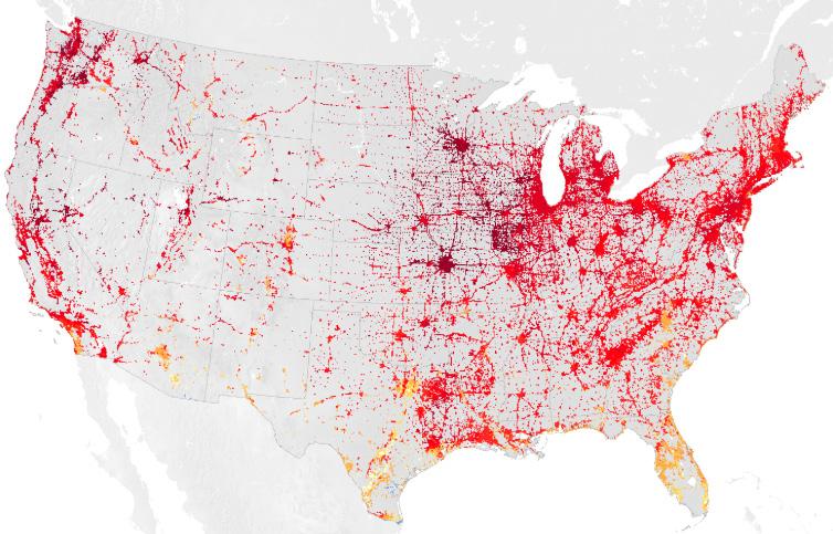
The urban potential of SUNTEX lies firstly in the creation of shaded spaces in places such as narrow roads, public squares, playgrounds or covered infrastructure (parking lots, bus stops, train stations, etc.). In this way, any space that cannot be shaded with plants and trees can be covered with shade-providing and energy-generating textile. Secondly, there is enormous untapped potential in retrofitting buildings with textile facades. In the Netherlands for example, there is approximately 2,200 square kilometres of facade surface, of which 660 square
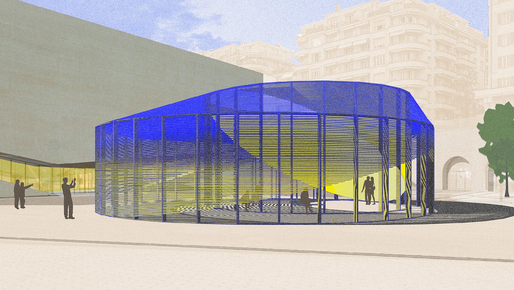
kilometres are suitable for generating solar energy (TNO 2023). The European Commission's Renovation Wave Strategy states that more than 220 million buildings (approximately 85% of the building stock) were built before 2001 and will largely still be standing in 2050. These buildings need to become climate neutral and their climate resilience must be improved. Especially in tall buildings and buildings that lack the load-bearing capacity of traditional solar panels, the facade provides an excellent surface for energy generation. Thirdly, SUNTEX can contribute to modular solutions where temporary spaces such as pavilions provide a shaded place for
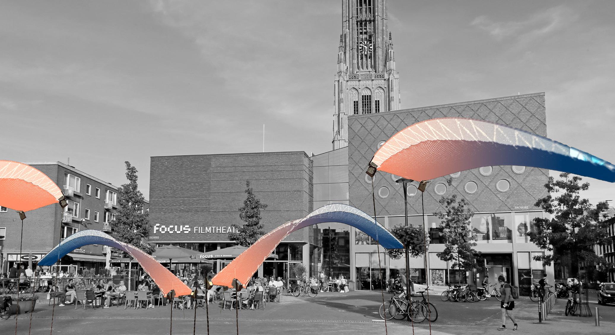
cultural activities in the city during hot summer months, while generating their own energy. “Ecliptica”, an ultralight and completely demountable pavilion covered with SUNTEX, is a good example of such a pavilion designed by Overtrders W. Future potential also lies in residential applications, where regular sun protection fabric can be replaced by SUNTEX. Due to its light and flexible nature, SUNTEX can even be retracted at undesirable hours, for example to let the heat of the day escape at night.
Fig. 5: Ecliptica pavilion covered with SUNTEX, designed by Overtreders W
Current SUNTEX development
SUNTEX has been in development for over 3 years. Much research has been done into the different yarns and best practices on securing the OPVs in a woven technical textile. This contained obtaining a tensile strength suitable for an architecture Type 1 fabric (van Dongen et al. 2023) and minimising the impact of loads on the OPVs. Recently the focus has switched to finding SUNTEX’ place in the construction market. In order to be qualified as a construction material such as an outdoor shade cloth, various requirements need to be met. Therefore, we are currently investigating the ageing, weathering and flammability properties of SUNTEX and how they can be improved. This includes weaving and testing high performance yarns against European norms for building
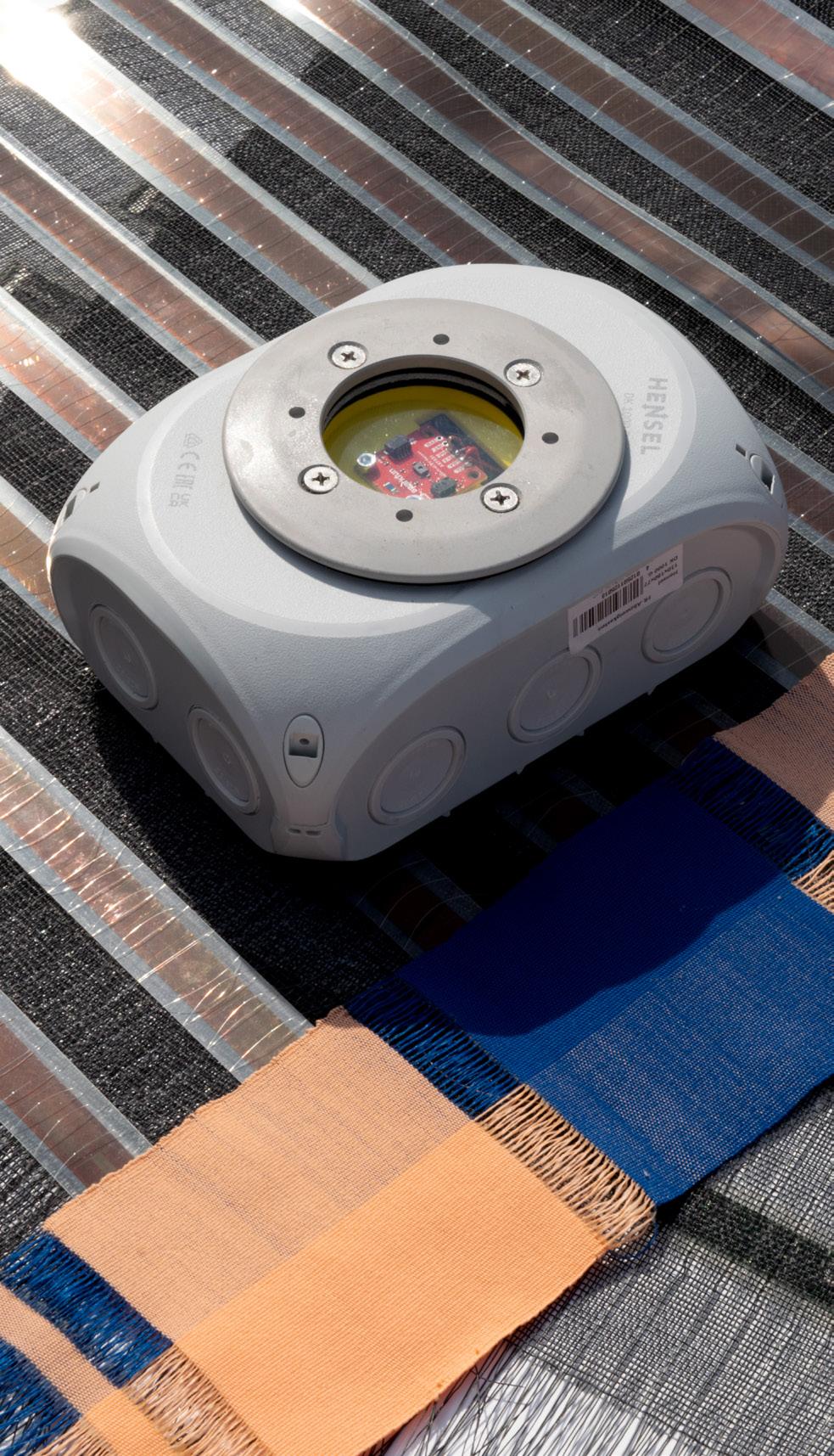
materials. As a part of this development, we are focusing on the UV deterioration of the yarn’s strength and the effect of moisture on the core. To test these factors, our recent development includes an outdoor testing station which measures the amount UV-radiation reaching the test subject. We are also designing, planning and constructing SUNTEX pilot projects to test applications such as shading constructions or facade-panels under real conditions in public spaces.This also allows us to explore general design concepts and ways to connect textiles to urban culture and understand energy consumption and storage scenarios in urban environments.
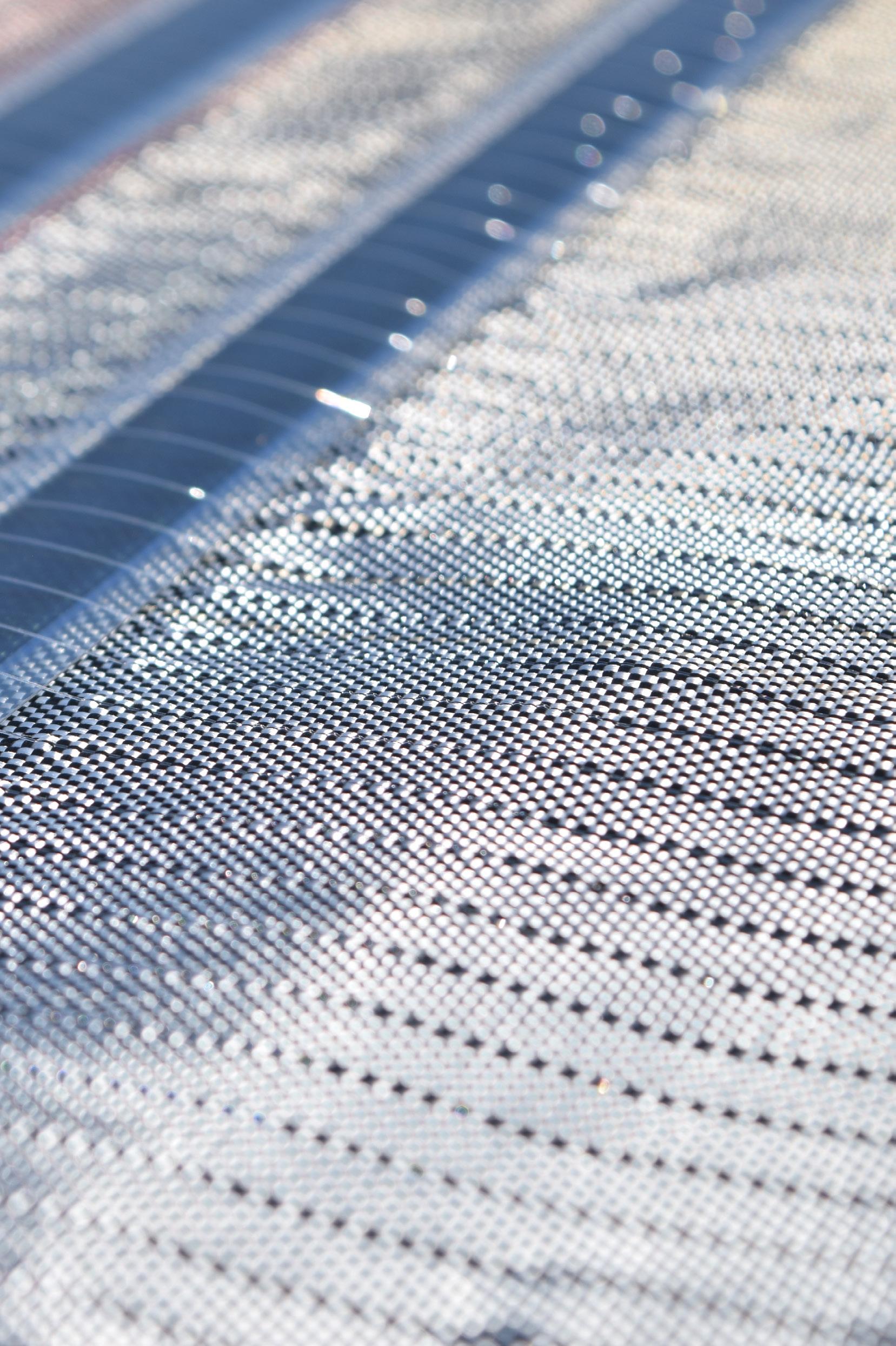
Fig. 7: Suntex mesh @ studio Pauline van Dongen
Fig. 6: Suntex fabric construction @ studio Pauline van Dongen
End note
Energy determines how we live our lives. It shapes our behaviour, our interactions with virtually everything around us and determines our expectations; such as when and how energy will be available to us and how quickly we move from A to B. Energy operates on the very personal scale of daily activities and routines, but also on the systemic scale of the electrical grid, which, when functioning smoothly, often fades into the background of our experience. Looking at energy through this socio-cultural lens reveals how global processes of energy transition and climate adaptation are not just a technological shift, as the transition from fossil fuels
to sustainable resources can be seen. These processes are also cultural shifts in our view and thinking about the world and offer an opportunity to reshape our living environment and relationships with energy.
We believe that multidisciplinary solutions for the challenges within the urban area are the future. Engineering and design go hand in hand in creating innovative materials and the integration of these materials can be promoted thanks to the new discipline of 'solar design' (The Solar Manifesto, 2022). Our ambition for SUNTEX is that it contributes to greater energy awareness, a new solar aesthetic and solving urban challenges.
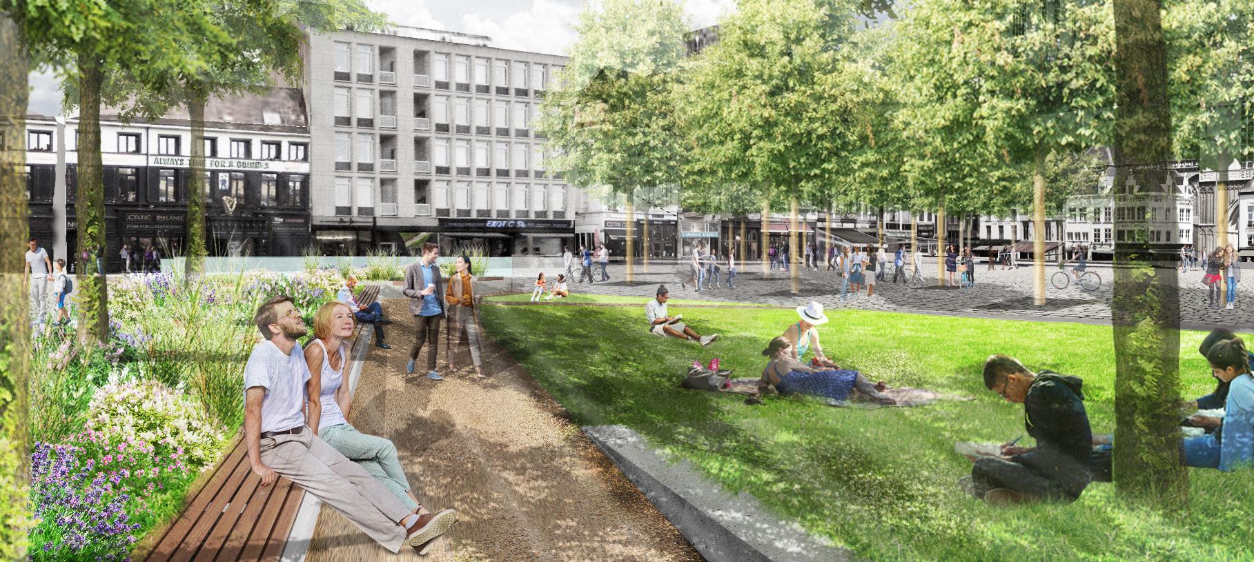
Fig. 8: Design sketch of SUNTEX shading elements on a public square @ studio Pauline van Dongen
References:
Almeida CRd, Teodoro AC, Gonçalves A. Study of the Urban Heat Island (UHI) Using Remote Sensing Data/Techniques: A Systematic Review. Environments. 2021; 8(10):105. https://doi.org/10.3390/environments8100105
Spanjar, G., Bartlett, D, Schramkó, S., luck, J., van Zandbrink, L, Föllmi, D. (2023) Cool Towns Intervention Catalogue: Proven solutions to mitigate heat stress at street-level. CoE City Net Zero, Faculty of Technology, Amsterdam University of Applied Sciences
The Lancet, Editorial (2021). Health in a world of extreme heat. Volume 398, Issue 10301, P641. https://doi.org/10.1016/S0140-6736(21)01860-2
The Solar Manifesto (2022). Retrieved from The Solar Movement: https://thesolarmovement.org/
van Heijningen, A., K leerekoper, L., & Schenk, S. (2019).K limaat slimme verstedelijking: Impactproject van het Deltaprogramma Ruimtelijke adaptatie. Watertorenberaad / Urbancore. https://ruimtelijkeadaptatie.nl/@220990/impactprojectklimaatslimmeverstedelijking/
van Dongen, P., Britton, E., Wetzel, A., Houtman, R., Ahmed, A. M., & Ramos, S. (2022).
Suntex: weaving solar energy into building skin. Journal of Facade Design and Engineering, 10(2), 141–160. https://doi.org/10.47982/ jfde.2022.powerskin.9
van Dongen, P., Britton, E., Wetzel, A., Houtman, R, Ahmed, A.M., Ramos, S. & Popescu, M. (2023) Suntex: weaving solar energy into building skin. Proceedings of the Tensinante Symposium , 486 - 498. https://re.public.polimi.it/bitstream/11311/1244078/1/Part%20 01_Part%2002_merged.pdf
Are you interested in participating in the Suntex research and looking for an internship or graduation project?
Please contact Harmen Werkman: harmen@tentech.nl
Fig. 9: Suntex with weathering station @ studio Pauline van Dongen
Pauline van Dongen
@studio Pauline van Dongen
Pauline is a pioneer and thought leader in the field of solar design. She works on products that make the cultural perspective of solar technology tangible and that invite a new relationship with the sun and energy awareness in people's direct living environment. Pauline is the inventor of SUNTEX, with which she further explores the technical textile and architecture market as a creative. She is also cofounder and curator of The Solar Biennale and The Solar Movement, which provide a platform for other solar energy designers. In 2019, she was the first fashion designer in the Netherlands to obtain a PhD from the Eindhoven University of Technology
@studio Pauline van Dongen
Anna J. Wetzel is a textile researcher, maker, and designer driven by curiosity and people. As an interdisciplinary connector, she explores the interplay between humans, nature, and technology through the lens of material innovation. Alongside her personal practice, which revolves around regenerative, natural fibre ecosystems of flaxlinen, Wetzel has been working for Studio Pauline van Dongen since 2021. Currently, Wetzel serves as the project leader of SUNTEX and is responsible for the technical weaving development of the textile.
@Tentech
Huub Visser is a Building Sciences student at The Hague University of Applied Sciences, completing his thesis at Tentech. Over the past six months, he has been actively engaged with SUNTEX, thoroughly enjoying the challenges and opportunities it provides. His role focuses on developing physical connections for the sides of the fabric and the underlying construction. Outside of his studies, Huub is passionate about creative projects, including illustrations and photography. In his spare time he finds challenges in various sporting activities, such as triathlons.
Huub Visser
Anna J. Wetzel
RETROFITTING WITH TEXTILES: an innovative approach to façade challenges
Giulia Procaccini
Arch. Ph.D | Politecnico di Milano - TextilesHUB
In modern architecture, retrofitting existing façades has become a critical strategy for enhancing building performance and extending their lifespan. Textile skins offer a promising solution to this challenge. These materials have always played a fundamental role within the construction sector, although their official recognition as building materials dates back only a couple of decades. However, textile materials not only provide functional benefits but also align with the growing demand for sustainable building practices. Today, buildings are responsible for approximately 40% of the EU's energy consumption and 36% of its greenhouse gas emissions, making the construction sector the largest energy consumer in Europe.
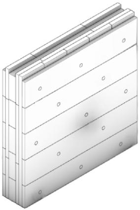
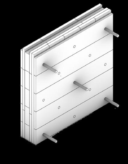
Fig. 1: Textile Façade Retrofit Strategies (TFRS)
QR1: Linkedin
QR 2 : website
With around 35% of EU buildings over 50 years old, and nearly 70% of the European building stock being energy inefficient, the urgency for effective renovation is clear. Despite predictions that 85-90% of existing buildings will still be in use by 2050, only about 1% of buildings are renovated each year.
Renovating existing buildings is essential to minimize time and waste production while maximizing the lifespan of building components. Yet, renovation remains a challenging process often overlooked due to substantial costs, time requirements, and the disturbance it causes to occupants. Despite the scattered and unclassified use of textiles in façades, as well as their limited use in retrofit applications, membranes are suitable for both temporary and permanent façade renovations, providing a promising avenue to overcome current retrofit constraints and promote widespread façade renovation efforts.
Traditional façade technologies, while effective, often face limitations in adaptability and efficiency. These retrofitting methods can quite often be invasive, costly, and time-consuming. Textile materials, known for their flexibility and lightweight properties, present an alternative that addresses these challenges. They offer a lightweight, adaptable, and aesthetically versatile option that can be tailored to meet specific performance criteria.
Advantages of Textile Skins for Façades
Textile skins are layers of technical fabrics applied to the exterior of buildings. These materials can be engineered to provide various functional benefits while maintaining or enhancing the building's appearance. One of the notable advantages of these materials is their lightweight
properties, allowing for aesthetic and functional retrofit enhancements without requiring substantial structural alterations. This is due to the minimized substructure needed for their application, avoiding excessive additional weights. Additionally, using membranes in façade and retrofit applications enables the coverage of vast areas, making them ideal for retrofitting expansive façade on a large scale.
Textile skins are made from high-performance fabrics such as PTFE (Polytetrafluoroethylene) coated glass fibers, ETFE (Ethylene Tetrafluoroethylene) foils, and PVC (Polyvinyl Chloride) coated polyester fabrics. These materials are known for their intrinsic properties, offering a combination of flexibility, lightness, thinness, and durability, making them suitable for both aesthetic and functional purposes in building design.
They can be used in various configurations, including:
• Tensioned Membranes: Applied in a stretched state, offering a smooth and continuous surface that can withstand external loads.
• Pneumatic Cushions: Inflated multi-layer systems that provide thermal insulation and structural stability.
• Laminated Foils: Thin layers that offer high transparency and are often used in applications requiring maximum light transmission.
Textile Façade Retrofit Strategies (TFRS)
Textile Façade Retrofit Strategies represent promising avenues for using textiles in retrofit applications. Developed as part of a PhD research project [Fig. 2], these strategies were evaluated through both qualitative
and quantitative assessments, including Life Cycle Assessment (LCA), Life Cycle Costing (LCC), and building simulation analyses. The identified strategies were tested against current methodologies in terms of LCA and LCC, and their impact on energy performance was analyzed by varying parameters such as solar and visible transmittance and reflectance, infrared
hemispherical emissivity and transmittance, conductivity, and airflow permeability.
Methods of Application
LCA and LCC comparative analysis: Comparison between selected TFRS and conventional solutions
Building energy simulations: Energy performance evaluation of selected TFRS 1. 2. 3. 5. 6. 4.
State of the Art analysis:
- Literature review
- Case-Studies analysis PART I
Qualitative assessment:
- Conventional VS textile strategies
- Theoretical development of TFRS
- Identification of promising TFRS
PART II
PART III
Considerations for TFRS: Challenges in the integration of TFRS
Guidelines and tools:
- Practical tools for implementing TFRS;
- Case-Study application of the framework
CONCLUSIONS
Fig. 2: Structure of the research methodology
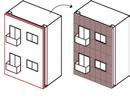
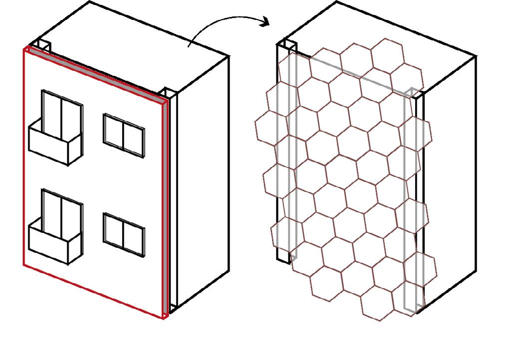
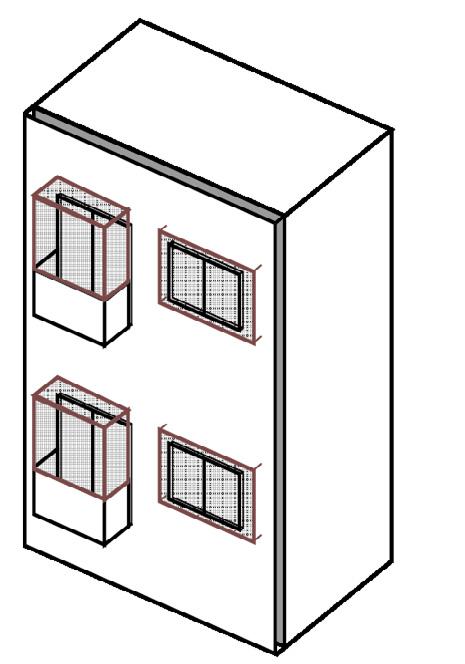
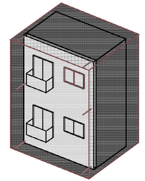
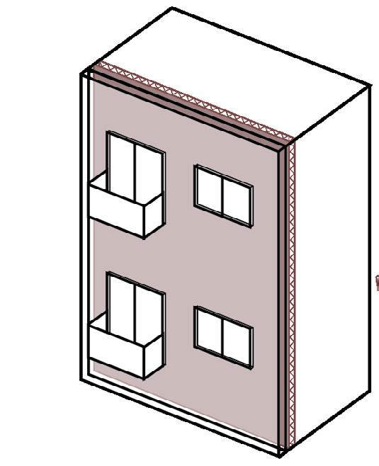
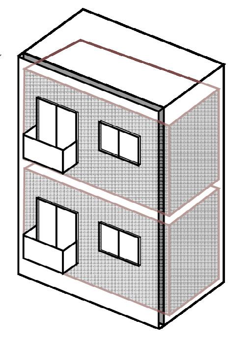
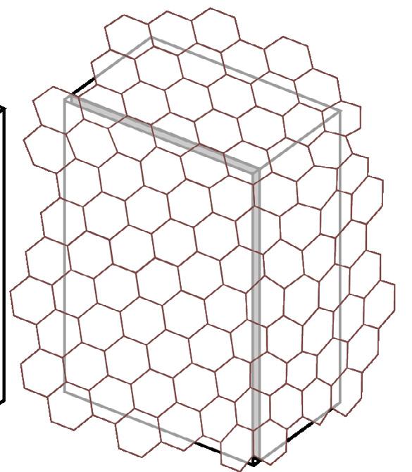
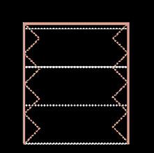
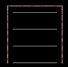
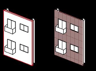
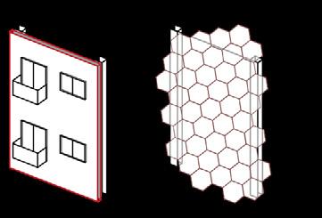
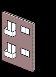
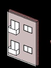
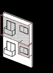
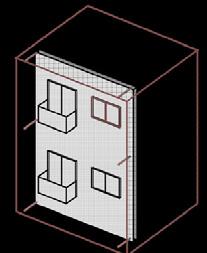
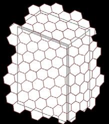
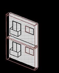
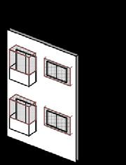
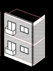
Textile materials are highly adaptable for retrofitting existing façades, offering several methods to enhance building performance and aesthetics. Their use in façade retrofit application can be classified in two main categories as Structural Membranes or Enclosures [Table 1]. Built on the general refurbishment classification proposed by Konstantinou T. [2014] and according to the retrofit strategy, textile materials offer several methods to enhance building performance and aesthetics:
• Replacing the Existing Façade: Textile skins can entirely replace existing façades or elements of them, providing a modern and efficient alternative to traditional materials. For example, tensioned membranes can replace aging cladding, offering a contemporary appearance.
• Adding Layers to the Existing Façade: Textile skins can be added as a new layer over existing façades, either internally or externally. Internally, an insulated textile layer can improve thermal performance without altering the building's exterior. Externally, textile skins can serve as sun-shading devices or decorative elements that enhance energy efficiency.
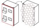
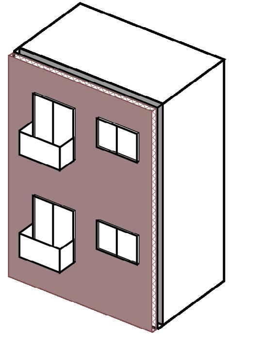
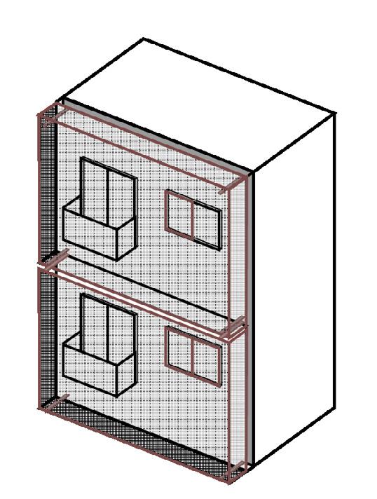
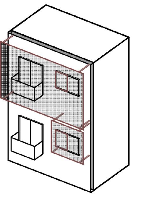
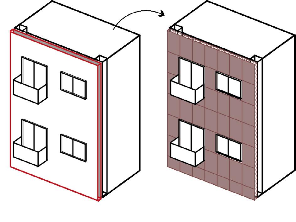
• Wrapping the Existing Façade: Textile skins can envelop existing structures, creating an additional exterior layer that enhances thermal resistance and reduces thermal bridging. This method is particularly useful for improving energy efficiency without significant structural alterations.
tExtilE façaDE rEtrofit applications
MEMbranEs
EnclosurEs
Replace
+ Limited additional weights;
± Total change of the appearance of the existing building.
Wrap it
+ Embracing of the whole building;
+ Creation of a new intermediate space / buffer zone
+ Self-supported (new) façade;
± Total change of the appearance of the existing building.
Add in
+ A new structure into the structure;
+ Preservation of the existing façade;
+ Self-supported (new) structure;
± Relevant trasformation of the interiors.
Replace
+ Limited additional weights;
± Total change of the appearance of the existing building.
Add on
Add in
+ Exterior and Interior application; ± Total change of the appearance of the existing building
Wrap it
Add on
+ Partial attachment to the structure; + Embracing of the existing façade; + Sun-shade; ± Partial change of the appearance of the existing building.
–Replacement of the existing façade.
– Increase in the thickness of the existing façade.
Table 1: Textile Façade Retrofit Applications
– Reduction of the interior space.
–Replacement of the existing façade.
Walls
–Application onto the existing façade; ± A little increase in the thickness of the existing façade.
– No buffer zone; no additional space; ± A little increase in the thickness of the existing façade.
Walls; Balconies; Windows
Walls
Walls
Walls; Balconies
Walls; Balconies; Windows
Identified Strategies and Benefits
The research identified nine Textile Façade Retrofit Strategies [Table 2] based on their retrofit strategy which differ in their method of implementation [Procaccini et al. 2023].
The use of textile skins in façade retrofitting demonstrates several significant advantages:
• Flexibility and Adaptability: Textile skins can be easily shaped and customized to fit any building design, allowing for creative and innovative architectural solutions.
• Lightweight: Compared to traditional building materials, textile skins add minimal weight to the structure, reducing the need for extensive structural reinforcement and substructure material for the cladding.
• Aesthetic Versatility: Available in various colors, textures, and translucency levels, textile skins offer endless design possibilities, allowing architects to achieve unique and modern façades.
• Durability and Maintenance: Advanced textiles are designed to withstand harsh environmental conditions, requiring minimal maintenance while providing long-term durability.
• Sustainability: Many textile materials are recyclable and contribute to sustainable building practices, aligning with the growing demand for environmentally responsible construction solutions.
• Economic: Textile skins often have lower installation costs compared to traditional materials.
Research Findings
The research highlighted the potential of textile specific materials as versatile sun-shading devices, which can be implemented either temporarily or permanently on façades. The findings indicated that applying these materials over existing façades could reduce the annual energy demands for buildings in Milano (Italy) by 27% to 32%, depending on the retrofitted building stratigraphy, primarily by minimizing summer cooling system consumption. These results vary according to the building's location, construction, retrofitted strategy design, and specific material properties used.
Environmental Impact
The environmental impact analysis of these strategies, compared to current methodologies, showed that textile materials, despite their polymeric nature and limited lifespan, represent a valid alternative to traditional methods. They achieve comparable, when not better, results in terms of Global Warming Potential (GWP), ozone depletion, acidification, and eutrophication values despite the necessity for substitution throughout extended lifecycles. Furthermore, these materials can be offset both economically and environmentally within a 50-year lifecycle scenario.
Final Reflections: Embracing Textile Innovations for a Sustainable Future
The integration of Textile Façade Retrofit Strategies (TFRS) offers a novel and promising approach to retrofitting existing façades. These strategies not only enhance the aesthetic, functional, and sustainable aspects of architectural structures but also pose unique challenges that demand comprehensive planning and thoughtful integration.
The aesthetic versatility of textile skins allows for dynamic architectural expressions, transforming a building’s visual identity while maintaining structural integrity. Economically, the lightweight nature of textiles simplifies installation processes and reduces costs, contributing to operational savings through improved energy efficiency. However, TFRS must align with evolving building codes that emphasize sustainability and energy efficiency. The development of comprehensive Environmental Product Declarations (EPDs) for textile materials is crucial for ensuring regulatory compliance and supporting sustainable urban development. Additionally, the effectiveness of TFRS significantly depends on local climate conditions, necessitating careful material selection to ensure durability and performance.
Despite these benefits, the widespread adoption of TFRS faces barriers such as technical challenges, economic considerations, regulatory constraints, and perceptual biases. Overcoming these barriers requires enhancing the durability of textiles, aligning designs with current building standards, and shifting public perception towards acceptance of these innovative solutions.
RetRofit stRategy: ReplaCe tensioned MeMbRane
Cushions
Replacement of the entire façade
Replacement of the entire façade with sandwich panels. In line
Walls: Membrane: textile ± insulation ± OBS
Replacement of the entire façade
Replacement of the entire façade with pneumatic cushions. In line
Walls and Windows: Pneumatic cushionsReplacing / Enclosing windows
Textile Membrane ± Insulation ± OBS
Heat protection: increased thermal resistance and air-tightness
Façade replacement; Disturbance for occupants; Prefabrication requires detailed survey; Cost
Different layers and finishing; Different insulation types and thicknesses
Pneumatic cushions -
Multiple layers
Heat protection; Passive solar heating
Façade replacement; Disturbance for occupants; Extra structure (and space) required; Cost
Different layers and transparency; Different insulation types and thicknesses
Replacement of the finishing
Addition of exterior insulation and finishing system. In line
and Balconies: Exterior Insulation and Finishing System
Heat protection: increased thermal resistance and air-tightness
Finishing replacement; Thermal bridging of the fixing; Water leakage risks
Different insulation types and finishing finishing
Table 2a: Textile Façade Retrofit Strategies
Textile Membrane + Insulation
Walls
ushions
RetRofit stRategy: addition
Replacement of entire façade
of the entire with pneumatic cushions. line
Windows:
Pneumatic cushions
Enclosing windows
RetRofit stRategy: WRap it
Pneumatic cushions
Multiple layers
protection; solar heating
replacement; for occupants; structure (and space) required; Cost layers and transparency; insulation types and thicknesses
Replacement of the finishing
Addition of exterior insulation and finishing system. In line
Walls and Balconies: Exterior Insulation and Finishing System
Textile Membrane + Insulation
Heat protection: increased thermal resistance and air-tightness
Finishing replacement; Thermal bridging of the fixing; Water leakage risks
Different insulation types and finishing finishing
CoveRing adding nesting
Addition from the interior
Addition from the exterior
Additional layer In line
Addition of an internal textile layer
Walls:
Textile Layer: air gap + textile finishing
(Partial) covering of the façade with textile membrane
Walls, Balconies and Windows: Screen OR Sun-shading
Air gap + Textile Finishing
Increased thermal resistance; New interior finishing; Detached from the existing
Lack of interior spaces; No thermal insulation
Different finishings
Textile Membrane
Improved acoustic performances; Sun-shading; Backlit or advertising surface
No thermal insulation; Opening for the shading; Overheating risk
Different layers and transparency; Different types and design of covering / shading elements
Table 2b: Textile Façade Retrofit Strategies
WRapping double skin enClosing
Wrapping of the entire building
Additional layer
Total covering of the building with textile membrane or pneumatic cushions.
Walls and Balconies: Second Skin / Buffer zone Windows: (En)closing windows OR Sun-shading
Textile Membrane + Insulation OR Pneumatic cushions
Heat protection; Thermal buffer unheated zone or ventilated façade; Create extra usable space; Sun-shading
Lack of exterior spaces; Overheating risk; Adequate ventilation needed; Extra structure (and space) required; Cost
Wrapping of the façade
Additional layer
Façade covering with textile membrane
Walls and Balconies: Second Skin / Buffer zone
Windows: Double casing OR Sun-shading
Textile Membrane + Insulation OR Pneumatic cushions
Heat protection; Thermal buffer unheated zone or ventilated façade; Sun-shading
Lack of exterior spaces; Extra structure (and space) required; Cost
Wrapping of the components
Additional layer
Façade elements covering with textile membrane.
Balconies: Integrated Balcony Additional Space Windows: Sun-shading
Textile Membrane ± Insulation
Thermal buffer unheated zone; Create extra usable space; Sun-shading;
Addition from the interior
Additional layer
Addition of an internal textile structure
Walls: Structure into structure (nest) Second interior skin
Textile Membrane ± Insulation
Increased thermal resistance; Interior bubble space; Detached from the existing
Different types and design of transparent and opaque elements
Different types and design of transparent and opaque elements
Overheating risk; Opening for the shading; Different layers and transparency; Different types and design of covering elements
Lack of interior spaces; Adequate ventilation needed; Cost
Different types and design of elements; Different insulation types and thicknesses
Overall, TFRS offer transformative potential for modern architecture, combining functionality with aesthetic flexibility to meet contemporary demands for sustainability and resilience. By addressing the multifaceted considerations associated with TFRS, architects and building professionals can effectively harness the potential of these innovative strategies, driving the future of sustainable and resilient urban environments.
In the dance of light and fabric, where tradition meets innovation, textiles whisper the promise of a greener, more beautiful future for our cities.
@Polimi Italy
Bibliography
1. K onstantinou, T. Façade Refurbishment Toolbox. Supporting the Design of Residential Energy Upgrades. Ph.D. Thesis, Faculty of Architecture and the Built Environment, TU Delft, Delft, The Netherlands, 2014.
2. Procaccini, G.; Prieto, A.; naack, U.; Monticelli, C.; onstantinou, T. Textile Membrane for Façade Retrofitting: Exploring Fabric Potentialities for the Development of Innovative Strategies. Buildings 2024, 14, 86 (2024). DOI:10.3390/buildings14010086
Giulia Procaccini is an architect and researcher in Technology of Architecture at Politecnico di Milano's ABC Department. She is a member of the Textile Architecture Network (TAN) group, related to the TextilesHUB laboratory. Giulia’s expertise lies in innovative building technologies and sustainable architecture. Her PhD research focused on Textile Facade Retrofit Strategies, integrating both qualitative and quantitative assessments to explore the potential of high-performance fabrics in modern architecture. Giulia has presented her research at numerous international conferences and has been published in leading architectural journals. She is passionate about merging tradition with innovation, aiming to drive the future of sustainable urban environments through her cutting-edge research and practical applications.
Giulia Procaccini
Are you passionate about leveraging parametric design to drive innovation in the built environment?
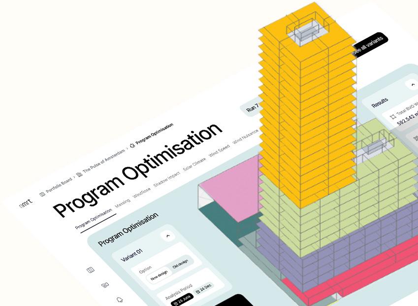
Join our team at OMRT as a parametric engineering intern. It’s an opportunity to immerse yourself in our self developed parametric tooling, skill building, and integral functional design, all within one unique position.
You’ll be at the forefront of doing parametric studies on the biggest Dutch and international residential real estate projects. Ever seen a wind simulation on 15.000 housing units work in realtime?
Perks & benefits:
Internship reimbursement
Travel costs are included
Hybrid working (3/2 office / work from home)
Lunch in the office
Access to powerful VM’s
Nice office in Amsterdam
Drinks, events and fun activities
Interested?
Mail us at hr@omrt.tech with your motivation letter and resume.
i-MESH: material networks, light textures and
Soft Architecture
Luciano Ambrosini, Alberto Fiorenzi
Contemporary architecture is undergoing a transition towards more flexible and adaptable forms, moving away from the rigidity of Modernism. Architects are seeking design solutions that can accommodate society’s changing needs while maintaining construction precision. This search has given rise to new spatial concepts, such as the visionary ideas of the Superstudio group and the “Soft Architecture” theory of Nicholas Negroponte. In the 1950s and 1960s, Yona Friedman developed “mobile architecture” based on flexible structures that users could modify over time. The Superstudio group critiqued functionalist architecture as suffocating and dehumanizing, instead proposing utopian visions
QR1: website
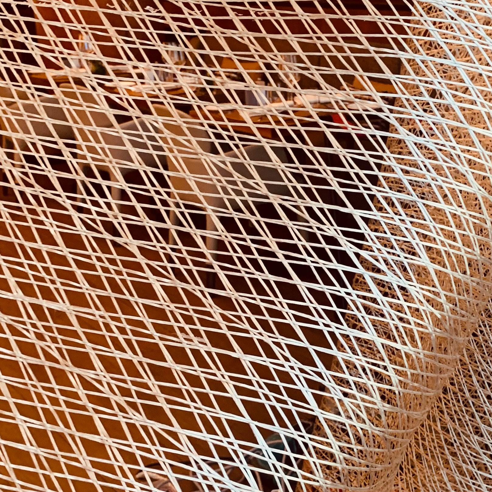
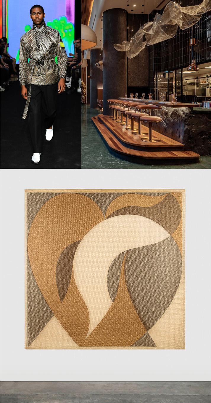
Fig. 1: Joël Robuchon International Le Grill Restaurant | Marriott International Hotel
of fluid, almost immaterial environments reconciling man and nature. Architects like Lina Bo Bardi and Cristiano Toraldo di Francia theorized flexible spaces supporting user activities rather than constraining them.
While High Tech architecture embodied some of these ideas, it often remained limited to a high-tech aesthetic. Concepts like Negroponte’s “Soft Architecture” envisioned buildings as interactive, cybernetic systems adapting in real-time to user needs, blurring physical and digital boundaries. This perspective has led to explorations of flexible, adaptable materials and structures, as seen in the work of artists and architects using fabric, paper, and other soft, ephemeral elements.
The evolution towards soft architecture has paved the way for developments in high-tech, multimedia, and parametric design. Textile membranes have long been used in architecture to create lightweight, flexible structures. However, conventional textile production methods impose limitations on the structural capabilities of fabric membranes. The emergence of new smart textiles like i-Mesh is opening new frontiers in the design of membrane in conceiving more flexible artefacts.
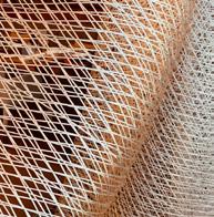
What is i-Mesh?
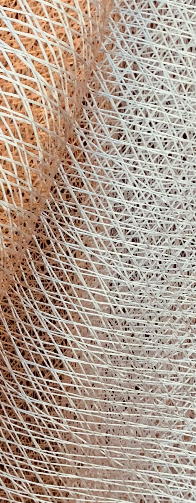
It is a technical, sustainable textile for architecture developed through years of marine and aerospace research. This innovative non-woven textile uses durable, high-performance fibers suitable for indoor and outdoor use. Designed for circularity, it's manufactured as custom-made panels, eliminating waste. Minimal scrap is repurposed for art and design (Fig. 2).
The team behind i-Mesh combines a passion for art and science, sharing this interdisciplinary perspective globally. Unlike conventional textiles with fixed weft and warp, i-Mesh's production system allows for orienting fibers in any direction. The team specialized in computational design provides tailored, shaped panels meeting precise architectural needs. Six materials are
Fig. 2: (top left) United Standard l SS20 Milano Fashion Week; (top right) Jun's restaurant, interior design Kings Group Ventures by 4space design; (bottom) contemporary tapestry "Trouble in Paradise" by Pierpaolo Pitacco (i-Mesh archive)
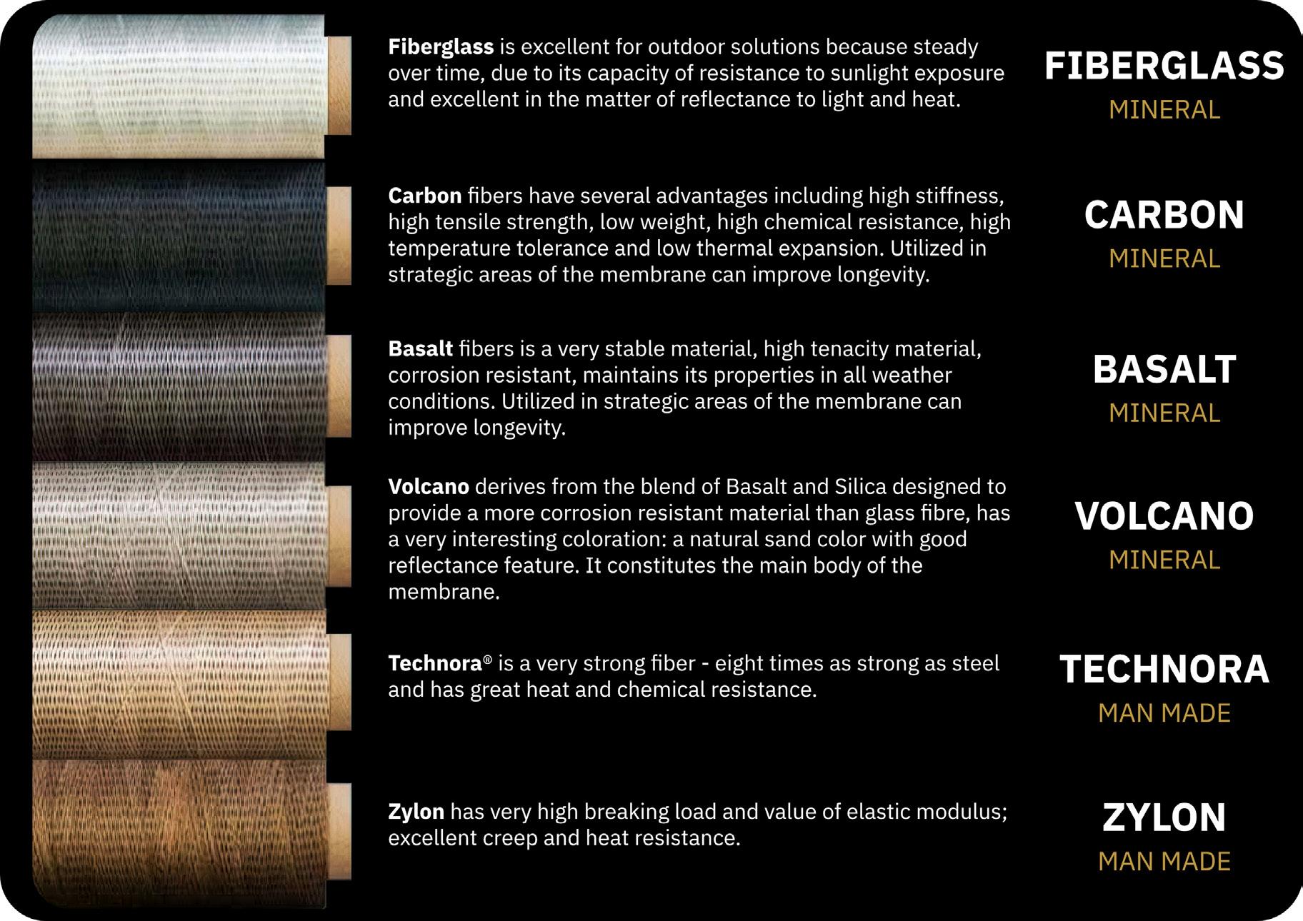
used, made from natural mineral fibers and blends. Each one has specific technical and aesthetic properties, and they are coated with a high-tech resin system (Fig. 3). i-Mesh unique composition and manufacturing process enables versatile applications, making it valuable for designers seeking high-performance, environmentally conscious solutions with attention to end-user comfort.
The docu-film “Softness” by Cristiana Colli and Francesca Molteni comprehensively explains i-Mesh, presenting reflections and narratives related to the epic of the thread, highlighting the venture and the fundamental nature of the raw material.
Fig. 3: Natural mineral fibers and blends used by i-Mesh
Softness. i-Mesh. Designing the city
Innovating Textile Design: the power of computational approach
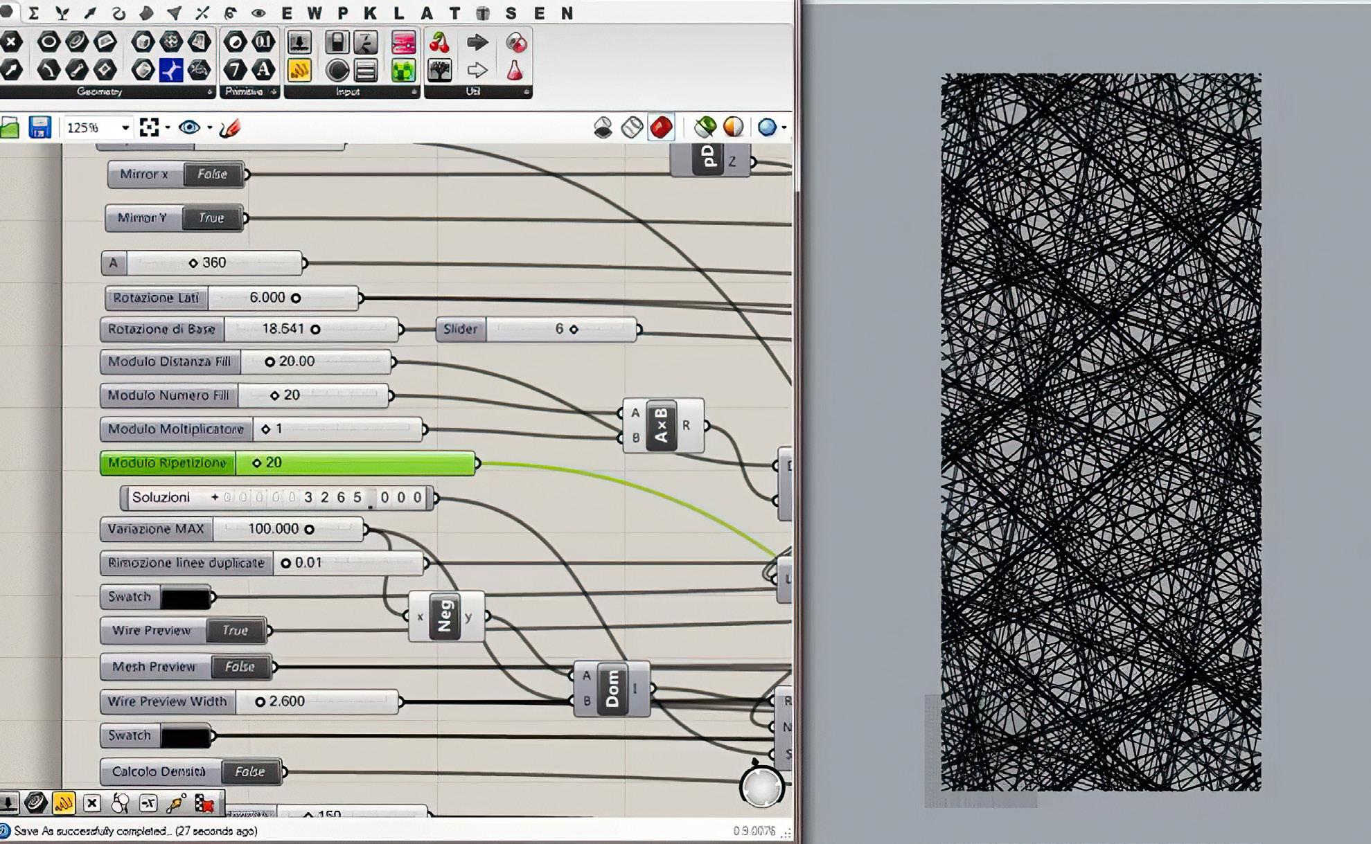
i-Mesh was created ten years ago using “Industry 4.0” production techniques, enabling “custom seriality”. The technological approach to panel design employs parametric and computational methods, a paradigm shifts well-known in the AEC industry. Software tools like Rhinoceros and Grasshopper (McNeel & Associates) are crucial for decoding and refining designers’ and architect’s requests, creating tailormade products
while managing contemporary architectural design complexity (Fig. 4). The ability to arrange fibers multi-axially and concentrate them in specific panel areas makes these highly flexible, technological design devices. This is especially valuable in projects evaluating environmental factors like thermo-hygrometric comfort and visual comfort to reduce glare and handle privacy. In i-Mesh’s typical workflow, the parametric approach allows evaluation and creation of geometric patterns as virtual final products, assessing fiber-by-fiber
Fig. 4: Example of engineering of i-Mesh panels through parametric modeling (F. Sicuranza)
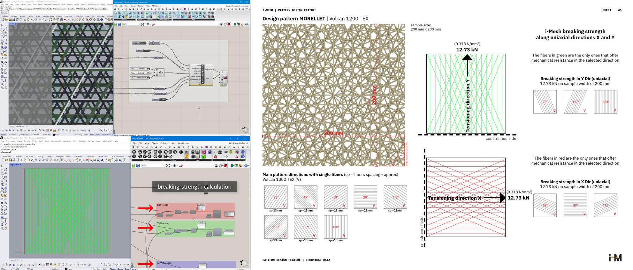
finishes and generating theoretical sample strength data sheets. Once the generative design phase is approved, manufacturing begins (Fig.5). While i-Mesh artifacts’computational morphogenesis is a highly technological process supported by technical and university laboratory tests, artisan expertise during production simultaneously enhances this unconventional textile material’s handmade aspect. Each production is skillfully crafted and finished through humanmachine operational synergy, fiber by fiber (Fig. 6).
Sample breaking strength by directions
Fig. 5: Generative design of the virtual sample and return of the theoretical directional resistance data sheet (L. Ambrosini)
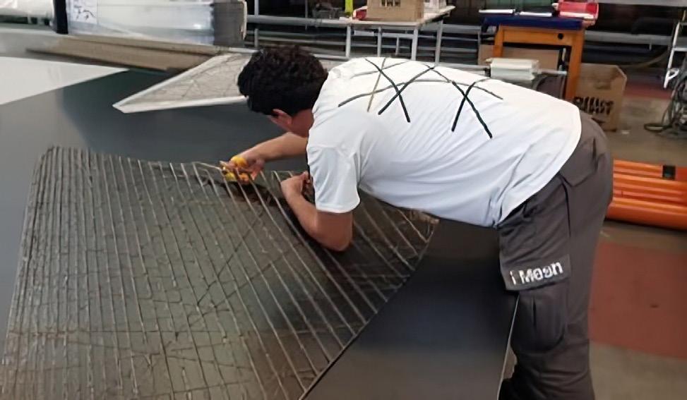
Fig. 6: Max is an expert i-Mesh craftsman who finishes a newly produced panel after the drafting phase
Randomized pattern by fibres percentage
Geometric pattern design test
Dubai Expo 2020: Thematic Concourse winning award shade structure
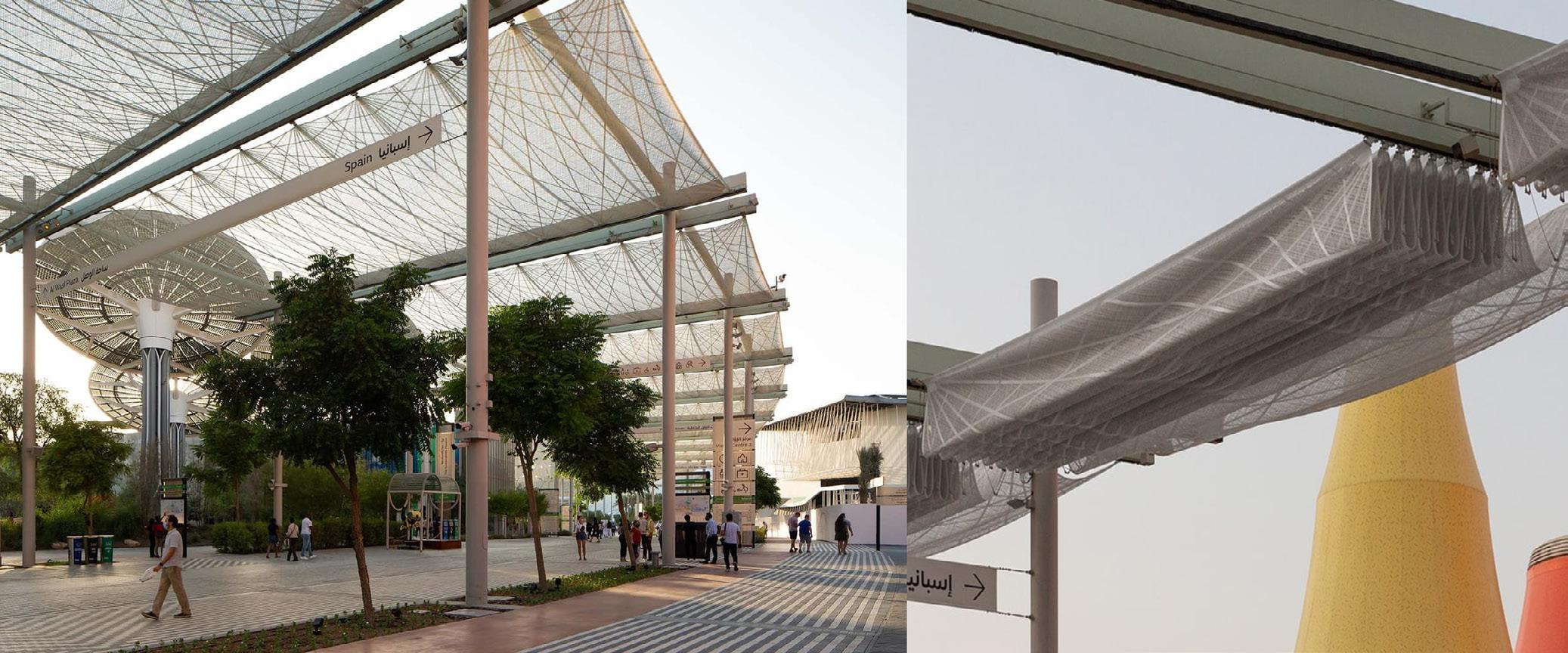
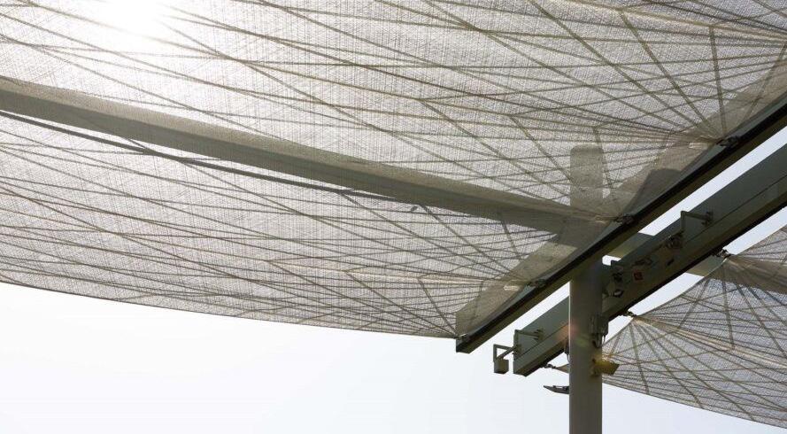
The shading structure for Expo 2020 Dubai’s thematic competition won second prize for Architectural Innovation of the Year (Built) at the 2022 Rethinking the Future Awards. Designed collaboratively by Werner Sobek AG, Lanaro srl and i-Mesh, it adapts to harsh climates using advanced technologies to improve microclimates and reduce CO² emissions. Expo 2020 Dubai’s interconnecting Promenade showcases innovative structural design through its unique retractable canopy system (Fig.7).
This sophisticated solution uses a lightweight, semipermeable membrane, providing effective shading while maintaining visual transparency and air circulation. The membrane’s unique open-weave structure allows precise control of solar transmittance and diffusion, optimizing
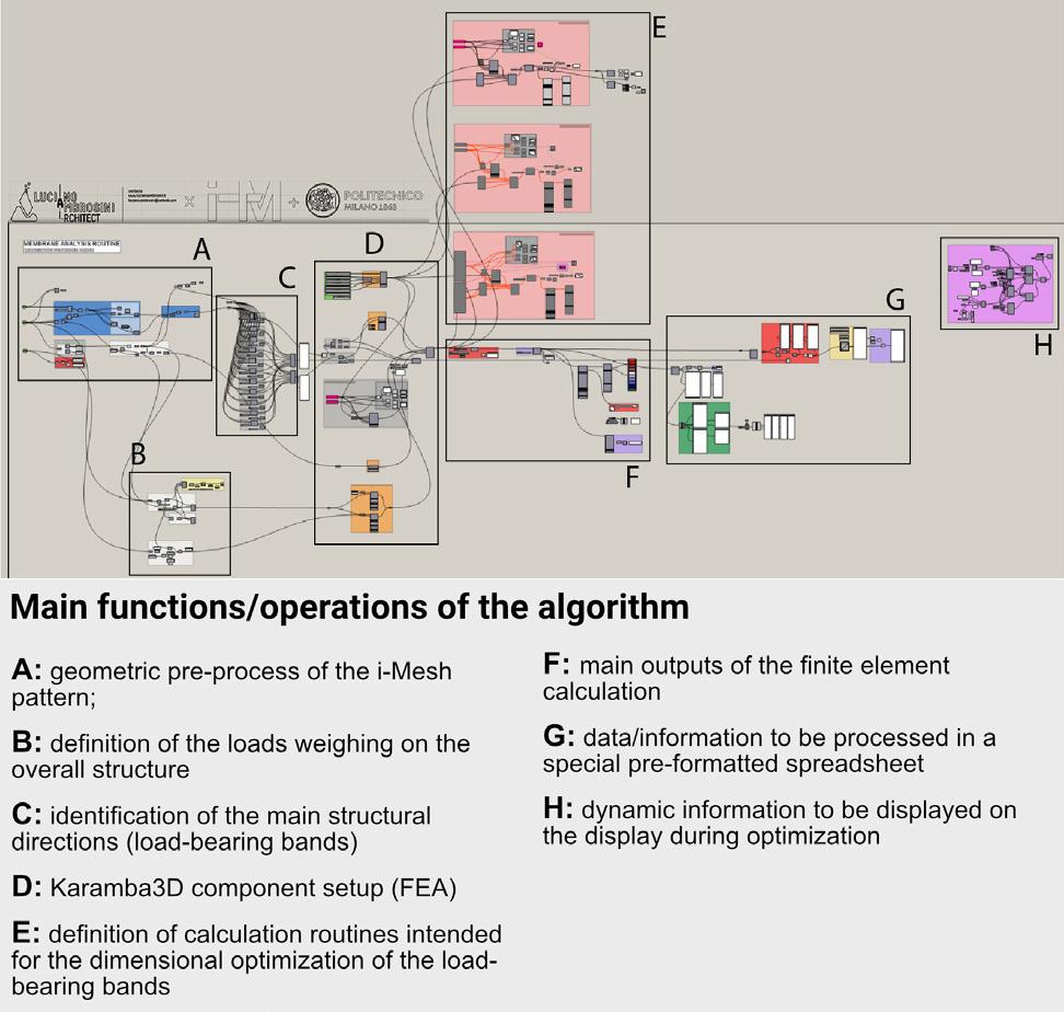
Fig. 8: Flow chart of the algorithmic definition of Grasshopper (L. Ambrosini / i-Mesh / PoliMi)
thermal comfort without compromising ambient light.
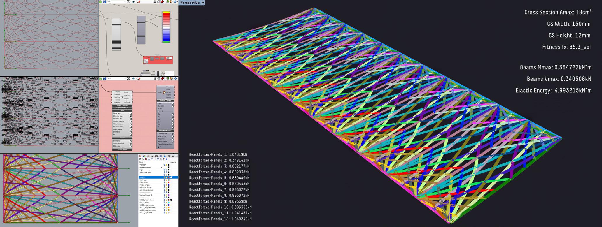
Werner Sobek’s team, experts in lightweight structures, leveraged the membrane's capacity for precise material optimization. Through advanced computational modelling and structural analysis, the i-Mesh Team achieved a high-performance design that reduced material use while meeting functional requirements. The team developed an algorithm able to analyse the structural behaviour of the original pattern (cf. [1]), incorporating a geometric preprocessing phase that reduces the i-Mesh pattern to finite elements as beams (Fig.8).
Perhaps most notably, the innovative fabric structure (23m x 12m modules) eliminated the need for conventional steel support beams typically required at 2-meter intervals in traditional pergola designs (Fig.9). This breakthrough in textile architecture not only enhanced the aesthetic quality of the canopy (Fig.10) but also yielded substantial
reductions in structural weight and material usage, thereby improving overall sustainability metrics for the project.
Membranes Structural Design Optimisation
Fig. 9: (Top left) Geometric simplification of the i-Mesh pattern; (centre left) identification of the finite elements' "tags"; (bottom left) identification of the structural bands; (right) optimization using an evolutionary solver to define the dimensions of the structural bands
Fig. 10: i-Mesh Dubai Pergola shade system (i-Mesh archive)
Enhancing i-Mesh projects with Environmental Design approach
For indoor and outdoor applications, it’s sometimes necessary to demonstrate the advantages of tailormade i-Mesh panels over traditional textiles. In environmental analyses evaluating site-specific conditions, simulations of solar radiation, daylighting, and annual glare are performed. Software like ClimatStudio and Ladybug Tools/Honeybee assess the material’s theoretical
behaviour in terms of energy, thermo-hygrometric comfort, and visual comfort. Considering the reflectance and transmittance characteristics of geometric patterns, previously lab-tested, it's possible to provide design guidance and optimize the final panel and its installation. This aligns with key thermo-hygrometric indices like PMV and UTCI, while also evaluating reductions in solar energy radiation in terms of shortwave and MRT (Mean Radiant Temperature) on surfaces affected
11: Optimization of the installation utilizing an evolutionary solver guided by the UTCI values beneath the membrane
Fig.
Fig 12: Solar radiation, direct sunlight, and UTCI assessment for a baseline and two distinct installation alternatives
by i-Mesh shading systems. For example, installation optimization can be correlated with increased comfort in terms of UTCI for horizontal shading installations, as shown in Fig. 11 and Fig. 12 of the triangular sail shading.
Advanced computational and environmental design can maximize the material’s technological flexibility by identifying panel areas most affected by solar radiation and its interaction with sun path. This allows selective fiber distribution only where necessary as in the Expo Dubai pergola system’s structural strategy. This approach was used in the case study shown in Fig. 12 for the protection project of the Roman Domus “Casa del Bicentenario” in the Herculaneum Archaeological Site (Italy).
Fig. 13: Environmental Design Analysis of the Domus Romana "Casa del Bicentenario" at the Herculaneum Archaeological Site (L. Ambrosini)
The parametric study mapped solar access in the Roman house, identifying critical areas for panelling focused on summer solar radiation impact. Finally, a gradient-colour map informed pattern design using a greyscale-based digitization method developed in-house. The design features four regions granting:
• High openness for ventilation
• Medium-high openness for views and late afternoon light
• Medium-low openness for shading and glare reduction
• Low openness protecting historic flooring from solar radiation
Technicians and conservation architects were provided with a technological product that respected the site’s cultural requirements while maximizing customization for each panel.
Conclusion
i-Mesh’s textile architecture bridges contemporary craftsmanship and technological innovation, embodying Soft Architecture principles. This approach, championed by Kengo Kuma since the 1980s and further examined by scholars, highlights flexibility, adaptability, and a harmonious relationship between architecture and its environment, aligning with the “kyokai” a Japanese technique for articulating space (cf.[3]).
i-Mesh born from technical expertise and artisanal awareness, transcends mere physical softness to express conceptual and functional flexibility. This material distinguishes itself through three fundamental
capabilities: identifying problems, constantly questioning them, and opening to new resolving visions. This careful design process imbues the product with character, originality, and special abilities, elevating the artisan to the role of a “signifier” capable of giving concrete form to practical issues. The versatility of this artefact is manifest in its ability to integrate with external landscapes and shape interior environments, creating unique atmospheres. Its architecture, composed of thin threads interwoven in multiple directions, blurs the boundary between functionalism and aestheticism, between shelter and interpretive lens of surrounding reality. This “soft architecture” invites a new perception of space and time, accelerating the transition towards architecture understood as a natural environment to inhabit, surpassing the limits of known reality and opening new perspectives in the dialogue between humans and their environment.
References
[1] Viscuso, S., Monticelli, C., Zanelli, A., & Fiorenzi, A. (2023). Development and validation of an experimental methodology for the characterization and FEM analysis of fibre-reinforced architectural meshes. In Proceedings of the TensiNet Symposium 2023, ISBN: 9789464787313 .
[2] Grifoni, R. C., Tascini, S., Cesario, E. and Marchesani, G. E. (2017). Cool façade optimization: A new parametric methodology for the urban heat island phenomenon (UHI), 2017 IEEE International Conference on Environment and Electrical Engineering and 2017 IEEE Industrial and Commercial Power Systems Europe (EEEIC / I&CPS Europe), Milan, Italy, 2017, pp. 1-5, doi: 10.1109/ EEEIC.2017.7977677.
[3] uma, K. (Ed.). (2010). yokai: a Japanese technique for articulalting space. Tankosha.
Luciano Ambrosini is an architect, researcher, and innovator at the intersection of technology and design. With a Master's in Architecture (cum laude) and a PhD in Sustainable Technologies from the University of Naples "Federico II", his academic path started in aerospace engineering before shifting to architecture. His career spans roles as R&D manager at i-Mesh, environmental design analyst at Foster & Partners, and consultant for the design of Apple Developer Academy. Ambrosini specializes in computational design, environmental analysis, and AI integration in architecture, developing cutting-edge tools like an AI toolkit for Grasshopper
VPL. As an independent researcher and frequent lecturer at institutions such as Politecnico di Milano and Georgia Tech, he pushes the boundaries of data-driven design in the AEC industry. With scientific publications and coded projects to his name, Ambrosini continues to pioneer innovative approaches that enhance architectural design through advanced technologies and collaborative workflows.
With a distinguished 30year career in the yacht industry, encompassing software, machine tools, design, and textiles, Alberto Fiorenzi invented i-Mesh, a revolutionary textile, in 2013. This groundbreaking textile, award-winning and innovative material, quickly attracted global attention from architects due to its sustainability and customizability. i-Mesh combines advanced, patented technology with zero-waste production techniques, and ultradurable, PVC-free materials, setting a new standard in textile design by transcending traditional weaving techniques to deliver exceptional beauty, strength,
and versatility. Fiorenzi’s work embodies a profound commitment to environmental issues and detachment from conventional politics. His company also sponsored the film “Softness,” directed by Francesca Molteni and written by Cristiana Colli, which explores and highlights sustainable design and material use through insights from prominent architects, artists, and philosophers. Additionally, Fiorenzi supports Stefano Mancuso’s initiative to plant three billion trees, further underscoring his dedication to ecological causes.
Alberto Fiorenzi @ i-Mesh
Luciano Ambrosini @ i-Mesh
BRIDGE DESIGN
ZERO ENERGY DESIGN
TECHNOLEDGE FACADE DESIGN
TECHNOLEDGEGLASS STRUCTURES
CSI – HERITAGE
(Conservation, Survey, Investigation of the Built Heritage)
CIRCULAR PRODUCT DESIGN
COMPUTATIONAL INTELLIGENCE FOR INTEGRATED DESIGN
MATERIALISATION: THE FUTURE ENVELOPE
TECNOLEDGE HEALTH AND COMFORT
TECNOLEDGE DESIGN INFORMATICS
ECO-FRIENDLY MATERIAL CHOICES
TIMBER ARCHITECTURE DESIGN
LAND ADMINISTRATION
BT SPOTLIGHT
Editor's Note by Swornava Guha
The Building Technology (BT) spotlight section features a selection of student work from the Building Technology track, one of five master’s tracks at Bouwkunde, TU Delft. This track is dedicated to research, technological innovation, and design, with a strong emphasis on the latest technologies and their market applications.
In this edition, the RuMoer committee is excited to present some of the exceptional work produced by students in the technical elective courses offered in the MSc Building Technology program during the third quarter of the 2023-24 academic year. To provide a fresh perspective and showcase a diverse range of student achievements, we've included three elective courses that were not featured in last year's summer edition.
E.P.I.C 3D
Simos Maniatis | Computational Intelligence for Integrated Design
Enahncement and precision for the iterative creation of 3D models. This research primarily focuses on harnessing the power of Generative Adversarial Networks (GANs) to generate 3D geometry, with a particular emphasis on controlling outputs through realistic variables such as structural parameters or energy performance. This adversarial process not only aims to produce data but also strives to refine the outputs to be increasingly indistinguishable from the genuine articles. By integrating these capabilities, this project seeks to have a complete prototype of the generative phase (3DGAN) of an AI tool, which not only generates geometry but also strives to refine it.
QR1: GitHub
Fig. 1: Different phases of the generative process.
The concept
The project is an attempt to embody the advancement of the domain of 3D data processing, utilizing a deep learning framework to develop and train 3D generative adversarial networks. This script should demonstrate an intricate synthesis of multiple neural network architectures , each chosen to enhance the handling, processing, and visualization of three-dimensional data, which is pivotal in numerous applications ranging from virtual reality to 3D printing.
A crucial section of EPIC3D is data preprocessing, where libraries like PyTorch and Open3D are invaluable for modifying and preparing datasets for training. PyTorch integrates with CUDA for efficient data-intensive operations, essential for complex 3D modeling.
In addition the intergration of numpy and scipy further complements this setup, providing robust capabilities for numerical operations and image manipulation—essential tools for preparing and augmenting the training data. This preprocessing stage is crucial for ensuring that the neural network learns to generate new 3D models that are both diverse and realistic.
Visualization tools play a pivotal role in the script not only for the data processing but also for debug and troubleshooting, since errors were bound to happen and feedback was necessary to attempt any kind of fix to the code. These tools are not merely auxiliary; they are integral to the model development process. They provide immediate, actionable insights into the training process, allowing for quick adjustments and optimizations. This real-time feedback is vital for fine-tuning the network,
ensuring optimal performance, and diagnosing issues promptly.
The script should be meticulously structured, indicating a high level of organization in managing the training sessions. It will include detailed setup for logging and saving model checkpoints, suggesting a prepared approach to handle extensive and potentially lengthy training processes. This organized framework not only will enhance the efficiency of the training sessions but also helps in maintaining a clear and systematic record of the model’s performance over time.
Furthermore, the script must have the ability to automatically detect and utilize available GPU resources to have am optimized computational strategy, ensuring that the training process is not only effective but also resource-efficient. The use of CUDA for GPU acceleration is indicative of the script’s advanced technical capabilities, allowing it to handle the computationally intensive tasks associated with training deep neural networks.
So to conclude the script should be divided into:
• Data Gathering
• Data Preprocessing
• Conversion to PyTorch Tensors
• Dataset Creation
• Training of the G.A.N
• Generate geometry with the trained model
The project went under differnt phases, trying to find the most suitable architecure of the neural network and format of geometry. Noticeable variations are found in these models:
• Model A : Point Clouds / Small number of layers for the neural networks of the generator and critic.
• Model B: Adjusted learning rate, increased training time and increased network depth.
• Model C: Inclusion of dropout layers and customised loss functions.
Directory
Fig. 3: The most recent framework
• Model D: KNN and edge convolution tryout.
• Model E: Switch to voxel grids.
The Application
To start building the dataset, a collection of 3D models had to be gathered. An object like a chair proved really useful at that point in time because of the huge variety of designs that can be found quite easily that adds a certain intensity of challenge to the generative phase of the tool.While also we can quite easily identify problems visually, if for example the tool cannot genrate unique objects and creates clones of the already existing dataset which highlights issues like overfitting or model convergence. That's why after many modifications and model versions,we reached the final framework below.
Fig. 2: Generated results of Model A
Fig. 4: Live-Streaming the generative process through Visdom
Conclusions and Feedback
After running the final model we can notice fluctuations in both networks (Generator and Discriminator) suggesting that the learning rates during the training of the model may be set too high, preventing the losses from converging to a minimum. Adjusting those values could potentially lead to more stable training.
With respect to the network architecture, if the loss is not decreasing satisfactorily, this could indicate that the architecture may not be sufficiently complex to capture the data distribution, or conversely, it may be overly complex, leading to overfitting. It could be beneficial to explore alternative adversarial loss functions, especially if the current loss functions are not yielding the desired results.
Incorporating regularization techniques such as spectral normalization or introducing noise to the inputs of the discriminator may improve training stability. As for the training duration, while it is important to train GANs for an adequate number of epochs to allow for convergence, there comes a point where additional training without modifications to the architecture or hyperparameters will not lead to further improvements.
In the end the model seems to be on the right track as it’s producing distinct models from different latent vectors. This is a positive sign that it’s learning to generate variety, which is important in GAN training to avoid repetition and ensure richness in output. While this doesn’t rule out all potential issues, it suggests that the network is picking up on how to diversify its creations, though there’s still room to see if it can maintain this with a wider range of inputs.
It’s an encouraging step, but continued monitoring and fine-tuning would be essential to confirm and possibly improve its capability to generalize from the data it’s trained on.
Next Steps
Developing E.P.I.C 3D was a formidable challenge. The academic setting provided essential materials that catalyzed my study, though I delved more into research than hands-on development. This approach aligns with the academic ethos, where understanding takes precedence over creation.
During the project, retrospection arose, particularly with the DGCGAN component. Initially, it seemed suitable for point clouds, but transitioning to voxel grids marked a turning point. Their tractable distribution in threedimensional latent space streamlined development, becoming pivotal to the project's success.
The realization that GANs in 3D design and engineering are burgeoning fields with untapped potential ignited my enthusiasm. However, robust Python skills are crucial; I found myself in a relentless pursuit of knowledge to meet my project's ambitions.
Ultimately, the rewards were immeasurable. The experience of creating something so complex was a testament to perseverance and passion. Looking forward, I’m eager to integrate the deep learning agent to optimize geometry. The fusion of generative capabilities and optimization is not just an academic exercise; it paves the way for A.I. tools tobe a topic of industry discourse , converging creation and enhancement.
2D topological dry-joint interlocking connection
Joint discrimination
Trained ML model
Interlocking?
INTERLOCKING CLASSIFICATION USING ML
Sanguk Ryu | Computational Intelligence for Integrated Design
Dry-joint interlocking systems offer a promising alternative to traditional construction methods. However, designing such structures demands thorough understanding of their topological complexities.
The focus in this project lies in developing machine learning model capable of discerning genuine interlocking structures and assessing the strength of their joints—a task that could be arduous for manual inspection by people.
I developed two machine learning models using custom datasets. The first model is an interlocking joint classifier that predicts true or false using Logistic Regression algorithm. The second model classifies joint stiffness (multiple label) using a Multilayer Perceptron (MLP).
Fig. 1: Machine learning: Interlocking classification process
Methodology
Fig. 2: Research methodology
Design Domain
The design domain encompasses a structure comprising two pieces: a black part (top) and a grey part (bottom), assembled within an 8x6 grid measuring 20x20mm, with a thickness of 40mm. This interlocking mechanism operates in a 2D joint configuration, facilitating assembly and disassembly in a 90-degree direction along the protruding part of the joint. A pulling force of 15kN was applied to the top part at the midpoint of the first row, while the part connected to the ground served as a fixed support for the bottom part. The structure's rigidity was determined by evaluating the displacement of the structure under this applied force.
Dataset Generation
To construct the dataset, Python scripts were used to create four types of interlocking data represented as an 8x6 matrix with binary values (1 and 0). The four data types are as follows:
• Interlocking True
• Interlocking but Not Functional
• Confusing but False
• Random False
Structural Analysis
Structural analysis with Karamba3D allowed for the extraction of representative displacement values, which are critical indicators of the structural integrity and strength of the interlocking joints. These values provide essential insights for accurate classification.
Data #1 Interlocking, True
Data #79 Not Functional, False
Data #189 Confusing, False
Data #314 Random, False
Fig. 4: Examples of generated data
Data #1 Displacement: 0,967
Data #2 Displacement: 3,813
#19 Displacement:
Fig. 5: Results of structural analysis using karamba 3D
Fig. 3: Design domain (schematic)
Label Boundaries Using K-Means Clustering
The current stiffness indicator for interlocking structures is displacement, which yields a wide range of result values. The objective at this stage is to perform accurate label clustering by uncovering hidden patterns not discernible through raw data alone, using K-means clustering, and unsupervised machine learning method. As a result, the optimal clustering number K was derived to be 4.
Interlocking T/F Classification Using Logistic Regression
In this step, a supervised machine learning approach is employed to accomplish the primary design objective. Given the necessity for a model suited to True/False binary classification, the widely utilized Logistic Regression model is chosen. The primary goal at this stage is to minimize the loss function associated with the model. Logistic Regression is implemented using Scikitlearn, a machine learning library in Python.
The initial model exhibited a low accuracy of 57% in predicting non-interlocking structures. However, this accuracy could be increased to 90% by feeding more data into the model.
Fig. 6: Elbow method & clustering result
Fig. 7: Logistic regression model confusion matrix & report True
Interlocking T/F Classification Using Logistic Regression
To predict five labels using an 8x6-bit image matrix as input, a machine learning model utilizing a Multilayer Perceptron (MLP) was employed. The objective of this architecture is to enhance label prediction accuracy. The dataset, prepared through previous processes where the function representing the interlocking joint serves as input and the classified label as output, is divided into training, validation, and test sets.
Initially, the model is trained using the training set and its performance is validated using the validation set. After iteratively fine-tuning the model, its prediction accuracy is determined using the test set. For the final neural network model, a total of 1,000 interlocking data were prepared with the ratio of each label adjusted as follows: Class A 46%, Class B 8%, Class C 7%, Class D 8%, and Class E 31%. The final model achieved a test accuracy of 89%.
This research paper delves into the preservation of the Bastion Promers façade in Naarden, employing a multidisciplinary approach to assess its condition and propose suitable interventions. The study integrates analyses of building materials, historical context, past interventions, and the surrounding environment to formulate effective preservation strategies. Central to this investigation is the development and testing of a hypothesis aimed at understanding the current state of the facade. Through a series of empirical tests including solubility testing, salt strip testing, capacitance meter analysis, infrared thermal imaging, and water drainage assessment, the hypothesis is rigorously evaluated. The findings reveal a significant challenge posed by high moisture content, fostering ideal conditions for biological growth. Additionally, the presence of salt-containing soil atop of the building or salt- containing brick in the facade leads to efflorescence.
Fig. 1: Bastion Promers, Naarden
Moreover, the combination of elevated moisture levels and adjacent parking facilities contributes to soiling on the facade. These results underscore the urgent need for targeted interventions to mitigate the detrimental effects of moisture and salt ingress while addressing the impact of environmental factors. By understanding the complex
facade in Naarden for future generations.
Areas for Inspection
Upon inspection, it was noted that Bays 4 and 9 experienced differing yet significant amounts of damage. Furthermore, both bays are located centrally within their respective wings of the façade, and thus could prove to be suitably comparable if inspected.
Material Identification
Petit Granit / Belgian Blue Limestone:
• Rock Type: Sedimentary Limestone
• Dutch name: (Belgische) Hardsteen
• Alternative names: Arduin
Fig. 2: Map of Naarden, Bastion Promers is highlighted in red
interplay between the building’s condition and its surroundings, this study aims to offer practical recommendations for preserving the Bastion Promers
The material’s compactness, visible fossils and immediate fizzling under a few drops of diluted HCl identify it as limestone. Through characteristics described in the Stone Atlas, the high concentration of fossils, hardcompact composition and grey-blueish colour indicate that the stone is Belgian Blue Limestone (van Hees et al., 2008).
Brick:
Overall, there is a mix of older and renovated bricks.
Fig. 3: Bay Diagram
Utrecht
4: Identified materials
There exist two typologies - a reddish-grey brick and a yellow brick.Knowing the age of the façade (constructed in 1877) and observing the rough and compact surface, slight irregularities and the lack of sharpness on the bricks’ edges with no visible nerves, the bricks used are determined to be soft mud-moulded using a machine (Lubelli, 2021a). These also have a standard Dutch brick size of 21,5 x 10,5 x 5,5 cm typical of that period.
Bedding / Pointing mortar:
After inspection of multiple sections of the façade where the pointing mortar had given way to show the bedding
mortar, we deduce that in older sections of the façade, they are both the same. When scratched with an abrasive instrument, the pointing mortar doesn’t powder. It is very hard. It has a whiteish colour and fine aggregate. This helps us deduce that the mortar is very plastic, with a lot of binder, so fat mortar. We hypothesize that it is natural hydraulic lime mortar.
Damage Types
During our examination of the main facade, we observed significant deterioration primarily characterized by efflorescence, soiling, and biological growth, indicative of environmental damages. There are not many instances of structural damage except some hairline and normal cracks.
A notable pattern emerged, particularly evident along the upper sections of the building, notably between the arches, where the majority of the damage was
Fig.
Fig. 5: Salt/Frost damage identified on façade
Hypothesis
As mentioned earlier, the main processes seem to point to environmental damage mostly salt damage occurring from excess moisture and presence of salt, sources of which we need to identify.
Fig. 6: Hypothesised damage mechanism for moisture-related damage concentrated. Salt crystallization, notably prominent on the right side of the structure, seemed to initiate a vertical cascade of deterioration, with efflorescence appearing above and subsequent damage below. Alongside salt crystallization, extensive brick degradation was evident, particularly with crumbling and scaling observed across the majority of bricks. Furthermore, within the arches, spalling was prevalent in several areas. Despite significant portions of the mortar being renovated, instances of instances of pushed-out mortar and absence were noted, with areas lacking renovation exhibiting powdering on the bricks. Notably, on the left side of the building, were both renovated and old bricks and mortar were observable, crypto efflorescence was detected, originating from the mortar and spreading onto the brick surface, exacerbating the aforementioned damages.
The observed efflorescence indicates a higher moisture content, likely originating from the soil atop the building. Efflorescence requires both moisture and salt, both of
damage in brick (spalling, crumbling etc.) and displacing the mortar. Additionally, elevated moisture levels create significant temperature differences, resulting in frost action and exacerbating the mentioned damages.
Investigation
To check for the hypothesis, we performed a variety of tests. Samples of identified efflorescence were collected from pushed-out pointing and spalled brick, exposing a white powdery deposit behind the pointing as well as white particles embedded in the brick. Subsequent
samples collected at a few locations were indicative of salt crystallization. These samples didn’t react to HCl and were soluble in water, thus determining the presence of soluble salts. These same deposit samples were subsequently tested for nitrates, chlorides and sulphates to determine salt type. The test for nitrates was inconclusive, however, the other tests indicated that the sample contained only a minimal amount of chloride (between 0 to 500 mg/L) and a substantial quantity of sulphates (1200 to 1600 mg/L). The presence of salts in the brick could be due to many reasons - from sulphates in the atmosphere due to pollution or in brick due to improper firing. The settled salt in the facade proceeds to causes crystallisation or efflorescence with the presence of moisture. These deposits accumulate over time, resulting in deterioration such as crumbling, spalling etc.
We also performed multiple capacitance moisture meter tests in locations across the façade to determine the levels of moisture present along both the vertical and horizontal axes. Measurements were taken on the pillars of selected bays as these show a majority of damage types (A and C) as well as readings in the inner bay (B). The number 200 indicates the highest possible moisture content measured. As expected, locations A and C had a higher moisture content than B which is more protected from rain. The moisture content was found to be significantly
Fig. 10: Capacitance meter test locations
Fig. 8: IR façade images, cold (likely wet) areas are darker
Fig. 9: Façade moisture content graph
which is concurrent with the concentration of damage. It is important to notice that the presence of salt makes the facade more inundated by moisture than it is because it makes water more conductive. Infrared testing (IR) also showcased areas of damp facade that corresponded with visible damage.
It was also discovered in our research that in 2019 an EPDM layer was installed on top of the façade to help reduce potential water permeation. However, said layer only extends 640 mm from the front of the façade.
Diagnosis
The solubility test and strip test prove the presence of soluble sulphate salts in the facade. The capacitance meter test and IR readings indicated high moisture content in the upper parts of the façade in line with a higher concentration of damages like spalling, crumbling, efflorescence etc. which proves the presence of moisture. The IR readings also revealed that moisture in the
upper parts of the facade begins from the cornice and concentrates between the arches. This leads us to believe there to be cracks or disintegration of the cornice leading to water seeping into the structure. Thus, the combined action of salt and percolation of water through the soil into the masonry is likely the cause for damages, compounded by improper drainage due the shape of the vaults. Despite this, the tests did not provide conclusive results; hygroscopic salts, lack of experience, or faulty equipment may have affected the results. Further, we encountered limitations in research due to non-destructive tests. Due to restrictions to enter the roof edge, we couldn’t take capacitance meter readings on the upper-most façade. Therefore, the gravimetric method should be used in the future, if restoration teams are willing to risk damage by drilling samples in a grid across the façade to better assess moisture content and evaluate the hypothesized cornice leak. Soil quality tests and monitoring of the deterioration would also help us develop our interventions from a stronger standpoint.
Fig. 11: Categorisation of damage types
Interventions
Our diagnosis identified two potential sources of moisture and salt: the earth mound on top of the bastion and the brick facade itself. To mitigate moisture ingress, the easiest solution would be to add a cantilever over the roof protecting the facade. However, applying such a solution would alter the façade’s aesthetics which hold significant architectural value. That is why we suggested nonfacade-altering solutions. Cleaning the façade of any existing biological growth and soiling would allow for an effective treatment to be applied. Steaming and brushing were identified as minimally abrasive methods.
• Preventing Additional Moisture:
The EPDM layer from the 2019 study was applied only to a depth of 640 mm. Thus we propose an assessment of its integrity and an extension of the layer to around 3000 mm to lesser the chance of leakage into the facade. It is essential to extend this layer to cover the roof cornice
as well which requires repair for any cracks that were inaccessible during our assessment.
The steep slope towards the roof edge increases water drainage issues. Our proposal involves reassessing the topography and contouring of the earth mound above the bastion to redirect water flow for improved drainage. Installing a drainage channel at the roof edge and adding of trees can also enhance water drainage.
• Extracting Existing Moisture:
To remove existing salt in the facade, we propose using a desalination poultice. It’s crucial to recognize that this process only addresses surface-level moisture, penetrating only 5 cm into the wall. Consequently, periodic repetition every three years is needed to manage ongoing salt migration. After desalination, the replacement of damaged bricks and mortar is imperative. We recommend employing bricks compatible with the original construction for a seamless visual finish.
Fig. 12: Overview of the proposed intervention process
BREATHABLE BIOBASED SYSTEM
Frederic de Milliano, Coco de Bok, Frank de Zwart, Beer van den Broek, Roan van Kammen | Circular Product Design
"Sustainable Construction: Integrating Timber and Reed for the Future"
The assignment of the course Circular Product Design (AR0145) was to create a comprehensive idea of a fragment of bio-based lab, which is to be built at the Green Village at the TU Delft. The fragment that has been prototyped is the external wall, but how has this been achieved?
To create a sustainable building element the aim was to design a locally sourced and bio-based building element, while meeting efficient manufacturing, assembling demountability and re-usability.
To achieve this, we explored and discovered some interesting paths to derive here. First of all we noticed the sustainability potential in
Fig. 1: Group picture with 1:1 Detail Prototype
minimizing the use of different materials in keeping the materials ‘pure’.
Timber seemed the obvious structural element when it comes to bio-based building, although, within acceptable material quantity, not insulating enough to cover the whole system. We, therefore focused on developing a system which is constructed out of two separable elements skin/ exterior and structure/interior, both elements represented by a distinct bio-based material.
For the timber system we focused on cross laminated timber, mainly due to the benefit of solid wood building. Solid timber systems make up for both the interior wall as the structure of the building which is aligned with our objective, due to the same reason this makesmore complex - timber frame construction on the side unnecessary.
Conventional CLT however has many layers of non bio based - toxic - adhesives, which are inseparable from
Product overview
Assembly principle
Fig. 2: Assembly principle
DOWEL LAMINATED TIMBER
The DLT will first be transported without the extended dowels. This is so that you can stack the sheets. The extended dowels will be hammered in on site.
FIRST LAYER OF REED
The dowels each have one small hole where the metal wire gets threaded through. This is for the mounting system. The first layer of reed is placed and spread out evenly.
the wood layers within the timber elements. This is where our focuses on DLT derived from. DLT - dowel laminated timber- is cross laminated timber in which the elements are joined by wooden dowels.
Besides keeping the material free of adhesive glues, the wood stays - as in its natural form - vapor open. Building damp-open allows for a constant flow of vapor moisture, avoiding condensation, which - when designed well - makes water repellent foils (to protect insulation or other elements) redundant. This breathability became a key element to achieve our goal for a simple bio-based building system.
For the exterior/skin element we decided to use Reeda bio-based, hyper-local and accessible - fibrous plant material. To result in a complete building system together with the wooden - DLT - structure/interior element this material needed to be insulating, water repellent, vapor open and meet exterior aesthetics. Reed seemed the perfect fit for this function.
SECOND LAYER OF REED
A horizontal stick made up of either wood or metal is placed so that it aligns with the dowels and then secured by tightening and knotting the wire.
Another layer of reed is placed at a higher point to go over the horizontal barrier. Then the same is done to secure the reed and stick.
STEPS 2-4 ARE REPEATED UNTILL AREA IS FILLED
HORIZONTAL BARRIER AND KNOTTING THE WIRES
To join the two elements together we focused on the joinery already at hand, in order to minimize material usage and complexity. The dowels which are used for the joinery in the inner layer gave opportunity to extend this to the outer layer. Quite literally. As a basis for the application of the Reed we the dowels are extended to form the basis for the skin layer assembly.
The innovative character of the material lies in using solid wood building in its departure - from conventional CLTtowards a bio-based breathable system. Although this ‘step forward’ makes use of ancient techniques like dowel joinery and reed thatching.
Demountability
We have chosen to create an integral system where the reed is directly attached to the dowels to not interfere with
4: Demountability Principle
Fig. 3: 1:5 (scaled) wall-roof corner connection.
Fig.
the DLT planks. This makes it possible for demountability as when needed you can remove the reed and saw away the excess dowels having a perfectly untouched piece of DLT.
Prototyping: The Process
Intitially we decided to use 6 layers of spruce wood for the design. The 4 layers layers eventually planned for the prototype are shown here. Due to material availability the eventual layers were different. Only two different planks are used, 18mm thickness and 69mm thickness.
• Sawing the planks
• Dehydrating the dowels
Although this 4 layer setup differs from our initial plan, based on existing DLT panels, the prototype still shows all the different orientations and a thicker core layer.
The arrangement of the planks is important. By selecting the boards and use the grain so they complement each other helps in creating a solid structure, especially because boards are usually not perfectly straight. For the long 69mm boards this arrangement was different than for the short 18mm planks. (figure 5b)
• Positioning of boards
• Clamping down the boards
Fig. 5a: Prototyping Process
5b: Prototyping Process
• Drilling and hammering dowels (figure 6)
The holes we drilled for the dowels were 17mm wide for 18 mm dowels. We dehydraded the dowels so they swell up in the holes, joining the wood boards even more.
• Editing the dowels (figure 7)
Since we had to flip the board we had to hammer the extended dowels multiple times to the other side. Not dehydrating these dowels made this possible.
• Sawing the DLT stack (figure 8)
The sawing blades could only cut 55 mm while the thickness of the DLT was more than 130mm, due to this reason we had to saw from both sides and use a hand saw to cut through it on a 45˚ angle.
Fig.
Fig. 6: Drilling and hammering dowels
Fig. 7: Editing the dowels
Fig. 8: Sawing the DLT stack
• Assembling wall to roof (figure 9)
After sawing the right elements we could assemble the wall and roof elements. To do this we used long screws, so dissassembly is possible in the future.
• Tatching the reed (figure 10)
Thatching reed is a specific skill. Altough we did extended research on the techniques, experience and the right tools seem crucial. At first reed was planned for the horizontal elements, as seen in examples, this did not seem strong enough, especially for the vertical wall cladding.
Fig. 9: Sawed DLT slack(above), assembling wall to roof (below)
Fig. 10: Thatching the reed
KICKSTART YOUR CAREER AT WITTEVEEN+BOS
At Witteveen+Bos, our engineers and consultants work every day on the challenges facing society both in the Netherlands and abroad. Totalling more than 1,400 colleagues, we use our expertise to make cities and regions accessible, liveable and sustainable. In our quest to fulfil this mission, we are always looking for new talents to join us.
In cities around the world, challenges related to climate change adaptation, accessibility, densification, the energy transition, safety, and liveability are stacking up. In these restricted and intensively used urban spaces, an integrated approach is required.
Come and make an impact with us
Witteveen+Bos believes in feasible, sustainable solutions achieved by combining expertise and approaching challenges in an integrated manner. Do you want to work in an inspiring environment where you can broaden your knowledge? Then scan the QR code to discover the opportunities available for internships, graduation projects, or your first job!
Visit our website for more information > https://www.witteveenbos.com/career/
Academic Year Event Chart
May 2024 to August 2024
02-06-2024
BouT dinner
04-07-2024 Graduation Party
05-07-2024 Alumni event
30-06-2024 End of academic year More events coming up! ?
30TH BOARD SIGNING IN
by Mauritz von Kardorff
Dear fellow BT-Students and Rumoer-Readers!
2024 marks the 30th anniversary of our beloved student association BouT! Over the past three decades, BouT has contributed to giving a voice to the BT Master students. The board and the committee members organized events, connected students to the industry, spread news from the academic world and most importantly, brought Building Technology enthusiasts together.
The 29th board kept the BouT values flourishing and organized an amazing year, which motivated us to join the board and continue BouT’s legacy. We would hereby like to thank the former board and all their committee members for their enthusiasm and motivated work, which we take as an example for the next year. In May 2024, our team of seven first year students took over. We celebrated the transition together with the former board over a memorable dinner with games, talks and food from our numerous home countries! Over the years, BouT has continuously represented the increasing diversity of backgrounds from BT Master students and our current team continues that tradition. The new board consists of our chairperson Mauritz von Kardorff, our responsible for Company Relations Jet Wiersma, Cansu Ersoy who runs the Events committee, Swornava Guha as the chief editor for the Rumoer magazine, Berk Adsan as chair for the Media and Promotion team, Daniel Lux as head of Education and Daan Schlosser who is in charge of the Study Trips.
As a team we are highly motivated to lead our committees over the next three quarters of this 30-year lustrum and already have some plans in mind for the celebration of
BouT. Furthermore, we aim to increase the connection between the various Master study tracks. With Daan, who studies in the MBE and Geomatics Masters, we already have great new links outside of BT. With 30 years of BouT, we also feel that this is a great time to increase the ties to the BT Alumni again. Therefore, we will create an event where alumni can gather, reconnect with old friends and meet the current BT students! Additionally, we aim for our amazing Rumoer magazine to reach a broader audience. We already started with a small step and set up a new reading corner in front of the BouT office. Students already frequent this space, which also aims to create a better visibility of our work at BouT. Finally, our traditional events this academic year will connect the students with exciting companies and academics again!
Our team sees BouT as a key quality of the BT Masters. Due to the great voluntary work of many BT students who join our committees, we are able to offer valuable experiences to everyone. For all our board members, these moments felt essential to our studies, and we aim to continue providing this to the next generation.
Our committees already have a great member base from the second-year students. However, we are looking forward for a lot of new motivated members from the September intake to join us. Together with them, we can realize our ambitious goals and celebrate a memorable 30th lustrum! We hope to see all of you at our BouT events and please feel free to reach out to any board member if you have any questions.
Happy Lustrum!
The 30th BouT Board, 2024-25
Mauritz von Kardorff
Chairperson of BouT
Mauritz is a Building Technology student at TU Delft. He holds a Bachelor’s degree in Architecture from ETH Zurich and a Bachelor’s degree in Hospitality Management from École hôtelière de Lausanne. His interest in technological innovation in architecture has led him to pursue his Master’s in BT. Mauritz’ has participated in research projects on additive manufacturing, worked as a computational design tutor and as an intern for international design firms. For BouT, he co-organised the spring 2024 Symposium and contributed to two Rumoer magazine publications. As this year’s chair, Mauritz is committed to create a stronger tie between the students and the alumni and foster collaboration between TU Delft’s Master tracks.
Jet Wiersma
Chair of Company Relations
Jet is a Dutch student, who obtained her bachelor’s degree in Architecture at TU Delft. She is currently studying Building Technology. During her second semester in her master she went on an exchange semester to NTNU in Trondheim, Norway. Where she took courses about Timber Structures, which is an interest of her. As BouT’s head of Company Relations she aims to connect students and companies with a broad spectrum to show student the big variety of opportunities the practical field has to offer.
Swornava Guha
Chair of Rumoer
Swornava is a Building Technology student at TU Delft. His professional journey as an Architect in New Delhi, India, spanning two years and eight months, and various internships have deeply influenced his passion for the dynamic realm of Building Technology. His keen interest lies in promoting sustainable material usage in construction and advocating for holistic building systems. Holding a Bachelor’s degree in Architecture (B.Arch) from the Manipal School of Architecture and Planning, India, Swornava brings a diverse academic background to his current pursuits.
As the 30th Chair of Rumoer and its Editor-in-Chief, Swornava is committed to expanding the magazine’s audience and enhancing its digital presence to engage with a broader readership.
Cansu Ersoy
Chair of Events
Cansu obtained her Bachelor Degree of Architecture at Bilkent University in Ankara in 2021, where she focused on sustainable design using computational tools and visualization. After graduating, she gained some insight of the industry by working in various offices as Architectural Designer and BIM Coordinator. Her interest in pursuing computational and sustainable design while improving her technical knowledge brought her to TU Delft. As BouT’s chair of Events, she hopes to enhance relations between students of different fields and enable insights into professions and research by organizing social and educational events such as symposiums, lunch-lectures or the annual debut event.
Berk Adsan
Berk is currently a Building Technology student at TU Delft. He obtained his Bachelor’s Degree in Architecture from Bilkent University in Ankara. He was the media coordinator as the board member in an association during his bachelor studies which encouraged him to strengthen the media and PR look of the 30th year of BouT association. Experiencing new cultures and networking during education is one of the maxims of Berk therefore he attended multiple summer schools around Europe and did his Erasmus+ in Prague. Apart from that, he has former barista experience which made enjoyable but disciplined work ethic one of his strong suits.
Daan Schlosser
Daan earned his Bachelor’s Degree in ‘Bouwkunde’ (Built Environment), specifically the project management track, at the University of Applied Sciences of Amsterdam in 2021. He is currently pursuing two Master’s degrees at TU Delft: an MSc in Management in the Built Environment and an MSc in Geomatics. Additionally, Daan is involved in the CampusNL research project, which examines trends and strategic choices in Dutch university campuses based on data from all 14 Dutch universities. He also works part-time at Infranea, a subsidiary of Sweco, focusing on point cloud applications and BIM software development for large-scale European infrastructure projects. As the chair of the study trips committee he tries to bring architectural education beyond the bounds of the university and is involved in bringing students of the various architecture master’s together.
Daniel Lux
Daniel graduated with a BSc in Architecture from the University of Technology Braunschweig. He also spent two semesters abroad in Bangkok studying architecture at the SoA+D of KMUTT. This is where he found his passion for architecture that has to adapt to many different environments. In combination with his professional experience in an architecture firm he decided to follow the path of architectural engineering at TU Delft with the Building Technology Track. As chair of Education he wants makes use of his many experiences in different academic environments to bring the needs of the multinational students together and offer them the best possible support with their worries and needs in their first year of BT.
Chair of Media & Public Relations
Chair of Study Trips
Chair of Education
BouT Board 2024 - 2025
INTEREST IN BOUT?
LUSTRUM EDITION
BouT celebrates its 30th year of successful organization, contribution to the fraternity of building technology, and cooperation with students, professionals and academicians. The Rumoer committee is excited to announce a special edition dedicated to commemorating this milestone.