
VOLUME 124 NO. 9 SEPTEMBER 2024

Presidential Address
Metallurgical slags: A drive to circularity and search for new research agenda by E. Matinde

VOLUME 124 NO. 9 SEPTEMBER 2024
Metallurgical slags: A drive to circularity and search for new research agenda by E. Matinde


Elias Matinde was born in rural Shurugwi, Zimbabwe, in 1978. He completed high school at Kwekwe High in 1997. Elias holds a PhD in Metallurgical Engineering from Tohoku University in Japan, a Master of Business Administration and a BSc (Hons) Metallurgical Engineering (cum laude) from the University of Zimbabwe, and Postgraduate Diploma in Higher Education from the University of the Witwatersrand. He is a Professional Engineer, a Fellow of the Southern African Institute of Mining and Metallurgy (SAIMM) and is a Past Fellow (2017-2018) of the African Science Leadership Program.
Elias has over 20 years of experience in academic and applied research, including more than 5 years at mid-senior to senior management levels leading multidisciplinary research, development, and innovation teams in extractive metallurgy. His areas of expertise include the development of nascent pyrometallurgical processes across various commodities, with particular emphasis on ironmaking, steelmaking, ferroalloy smelting, and production of technological and base metals.
He is a co-author of a specialist textbook on waste production and utilization in the metal extraction industries (Taylor & Francis, 2017) and a book chapter on metallurgical unit processes and the production of slags (Royal Society of Chemistry, 2021).
Elias is a researcher whose passion lies in developing fit-for purpose technologies and pyrometallurgical flowsheets capable of processing a variety of feed materials at high productivity but with less energy consumption and CO2 emissions.

His current research activities are focused on developing integrated pyrometallurgical flowsheets and sustainable technologies to recover valuable metals from industrial and urban wastes such as mining and metallurgical wastes, e-wastes, and spent autocatalysts and batteries, among other materials, in line with the Sustainable Development Goals (SDGs) and other emerging nexuses.

He is an avid reader of scholarly works on technological and economic catch-up within the context of using natural resources as platforms for technological upgrading and foundations for industrialization.
Elias joined the SAIMM in 2011 and was extensively involved in revitalizing the Institute‘s Zimbabwean Branch, where he was renowned for organizing ‘sold-out’ technical visits and networking events. He has actively supported the organizing of a number of successful conferences and was instrumental in organising the 1st International Conference on Southern African Rare Earths and the International Conference on Enhanced Use of Thermodynamic Data in Pyrometallurgy Teaching and Research. Elias also served on the SAIMM Council for over eight years.

OFFICE BEARERS AND COUNCIL FOR THE 2024/2025 SESSION
Honorary President
N. Tsengwa
President, Minerals Council South Africa
Honorary Vice Presidents
Gwede Mantashe
Minister of Mineral Resources and Energy, South Africa
P. Tau
Minister of Trade, Industry and Competition, South Africa
Blade Nzimande
Minister of Higher Education, Science and Technology, South Africa
President E. Matinde
President Elect
G.R. Lane
Senior Vice President
T.M. Mmola
Junior Vice President
M.H. Solomon
Incoming Junior Vice President
S.J. Ntsoelengoe
Immediate Past President
W.C. Joughin
Honorary Treasurer
W.C. Joughin
Ordinary Members on Council
W. Broodryk
Z. Fakhraei
B. Genc
K.M. Letsoalo
S.B. Madolo
M.A. Mello
K. Mosebi
Co-opted Council Members
A.D. Coetzee
L.T. Masutha
M.C. Munroe
S.M. Naik
G. Njowa
S.M. Rupprecht
A.T. van Zyl
E.J. Walls
Past Presidents Serving on Council
N.A. Barcza C. Musingwini
R.D. Beck S. Ndlovu
Z. Botha J.L. Porter
V.G. Duke M.H. Rogers
I.J. Geldenhuys G.L. Smith
R.T. Jones
G.R. Lane – TP Mining Chairperson
Z. Botha – TP Metallurgy Chairperson
K.W. Banda – YPC Chairperson
C.T. Chijara – YPC Vice Chairperson
Branch Chairpersons
Botswana K. Mosebi
DRC K.T. Kekana (Interim Chairperson)
Johannesburg N. Rampersad
Limpopo M.S. Zulu
Namibia T. Aipanda
Northern Cape Vacant
North West Vacant
Pretoria P.G.H. Pistorius
Western Cape Vacant
Zambia N.M. Kazembe
Zimbabwe L. Shamu
Zululand Vacant
*Deceased
* W. Bettel (1894–1895)
* A.F. Crosse (1895–1896)
* W.R. Feldtmann (1896–1897)
* C. Butters (1897–1898)
* J. Loevy (1898–1899)
* J.R. Williams (1899–1903)
* S.H. Pearce (1903–1904)
* W.A. Caldecott (1904–1905)
* W. Cullen (1905–1906)
* E.H. Johnson (1906–1907)
* J. Yates (1907–1908)
* R.G. Bevington (1908–1909)
* A. McA. Johnston (1909–1910)
* J. Moir (1910–1911)
* C.B. Saner (1911–1912)
* W.R. Dowling (1912–1913)
* A. Richardson (1913–1914)
* G.H. Stanley (1914–1915)
* J.E. Thomas (1915–1916)
* J.A. Wilkinson (1916–1917)
* G. Hildick-Smith (1917–1918)
* H.S. Meyer (1918–1919)
* J. Gray (1919–1920)
* J. Chilton (1920–1921)
* F. Wartenweiler (1921–1922)
* G.A. Watermeyer (1922–1923)
* F.W. Watson (1923–1924)
* C.J. Gray (1924–1925)
* H.A. White (1925–1926)
* H.R. Adam (1926–1927)
* Sir Robert Kotze (1927–1928)
* J.A. Woodburn (1928–1929)
* H. Pirow (1929–1930)
* J. Henderson (1930–1931)
* A. King (1931–1932)
* V. Nimmo-Dewar (1932–1933)
* P.N. Lategan (1933–1934)
* E.C. Ranson (1934–1935)
* R.A. Flugge-De-Smidt (1935–1936)
* T.K. Prentice (1936–1937)
* R.S.G. Stokes (1937–1938)
* P.E. Hall (1938–1939)
* E.H.A. Joseph (1939–1940)
* J.H. Dobson (1940–1941)
* Theo Meyer (1941–1942)
* John V. Muller (1942–1943)
* C. Biccard Jeppe (1943–1944)
* P.J. Louis Bok (1944–1945)
* J.T. McIntyre (1945–1946)
* M. Falcon (1946–1947)
* A. Clemens (1947–1948)
* F.G. Hill (1948–1949)
* O.A.E. Jackson (1949–1950)
* W.E. Gooday (1950–1951)
* C.J. Irving (1951–1952)
* D.D. Stitt (1952–1953)
* M.C.G. Meyer (1953–1954)
* L.A. Bushell (1954–1955)
* H. Britten (1955–1956)
* Wm. Bleloch (1956–1957)
* H. Simon (1957–1958)
* M. Barcza (1958–1959)
* R.J. Adamson (1959–1960)
* W.S. Findlay (1960–1961)
* D.G. Maxwell (1961–1962)
* J. de V. Lambrechts (1962–1963)
* J.F. Reid (1963–1964)
* D.M. Jamieson (1964–1965)
* H.E. Cross (1965–1966)
* D. Gordon Jones (1966–1967)
* P. Lambooy (1967–1968)
* R.C.J. Goode (1968–1969)
* J.K.E. Douglas (1969–1970)
* V.C. Robinson (1970–1971)
* D.D. Howat (1971–1972)
* J.P. Hugo (1972–1973)
* P.W.J. van Rensburg (1973–1974)
* R.P. Plewman (1974–1975)
* R.E. Robinson (1975–1976)
* M.D.G. Salamon (1976–1977)
* P.A. Von Wielligh (1977–1978)
* M.G. Atmore (1978–1979)
* D.A. Viljoen (1979–1980)
* P.R. Jochens (1980–1981)
* G.Y. Nisbet (1981–1982)
A.N. Brown (1982–1983)
* R.P. King (1983–1984)
J.D. Austin (1984–1985)
* H.E. James (1985–1986)
H. Wagner (1986–1987)
* B.C. Alberts (1987–1988)
* C.E. Fivaz (1988–1989)
* O.K.H. Steffen (1989–1990)
* H.G. Mosenthal (1990–1991)
R.D. Beck (1991–1992)
* J.P. Hoffman (1992–1993)
* H. Scott-Russell (1993–1994)
J.A. Cruise (1994–1995)
D.A.J. Ross-Watt (1995–1996)
N.A. Barcza (1996–1997)
* R.P. Mohring (1997–1998)
J.R. Dixon (1998–1999)
M.H. Rogers (1999–2000)
L.A. Cramer (2000–2001)
* A.A.B. Douglas (2001–2002)
* S.J. Ramokgopa (2002-2003)
T.R. Stacey (2003–2004)
F.M.G. Egerton (2004–2005)
W.H. van Niekerk (2005–2006)
R.P.H. Willis (2006–2007)
R.G.B. Pickering (2007–2008)
A.M. Garbers-Craig (2008–2009)
J.C. Ngoma (2009–2010)
G.V.R. Landman (2010–2011)
J.N. van der Merwe (2011–2012)
G.L. Smith (2012–2013)
M. Dworzanowski (2013–2014)
J.L. Porter (2014–2015)
R.T. Jones (2015–2016)
C. Musingwini (2016–2017)
S. Ndlovu (2017–2018)
A.S. Macfarlane (2018–2019)
M.I. Mthenjane (2019–2020)
V.G. Duke (2020–2021)
I.J. Geldenhuys (2021–2022)
Z. Botha (2022-2023)
W.C. Joughin (2023-2024)
S.O. Bada
R.D. Beck
P. den Hoed
I.M. Dikgwatlhe
M. Erwee
B. Genc
R Hassanalizadeh
R.T. Jones
W.C. Joughin
A.J. Kinghorn
D.E.P. Klenam
D.F. Malan
D. Morris
C. Musingwini
S. Ndlovu
P.N. Neingo
A. Nengovhela
S.S. Nyoni
M. Phasha
P. Pistorius
P. Radcliffe
N. Rampersad
Q.G. Reynolds
I. Robinson
S.M. Rupprecht
K.C. Sole
T.R. Stacey
D. Vogt
F. Uahengo
International Advisory Board members
R. Dimitrakopolous
R. Mitra
A.J.S. Spearing
E. Topal
D. Tudor
Editor /Chairperson of the Editorial Board
R.M.S. Falcon
Typeset and Published by
The Southern African Institute of Mining and Metallurgy PostNet Suite #212 Private Bag X31 Saxonwold, 2132
E-mail: journal@saimm.co.za
Printed by Camera Press, Johannesburg
Advertising Representative
Barbara Spence
Avenue Advertising


Journal Comment: Is industry hiding its light under the proverbial bushel? by R.M.S. Falcon
Profiles of the Branch Chairpersons
Presidential Address: Metallurgical slags: A drive to circularity and search for new research agenda by E. Matinde ...................................................................
THE INSTITUTE, AS A BODY, IS NOT RESPONSIBLE FOR THE STATEMENTS AND OPINIONS ADVANCED IN ANY OF ITS PUBLICATIONS.
Copyright© 2024 by The Southern African Institute of Mining and Metallurgy. All rights reserved. Multiple copying of the contents of this publication or parts thereof without permission is in breach of copyright, but permission is hereby given for the copying of titles and abstracts of papers and names of authors. Permission to copy illustrations and short extracts from the text of individual contributions is usually given upon written application to the Institute, provided that the source (and where appropriate, the copyright) is acknowledged. Apart from any fair dealing for the purposes of review or criticism under The Copyright Act no. 98, 1978, Section 12, of the Republic of South Africa, a single copy of an article may be supplied by a library for the purposes of research or private study. No part of this publication may be reproduced, stored in a retrieval system, or transmitted in any form or by any means without the prior permission of the publishers. Multiple copying of the contents of the publication without permission is always illegal. U.S. Copyright Law applicable to users In the U.S.A. The appearance of the statement of copyright at the bottom of the first page of an article appearing in this journal indicates that the copyright holder consents to the making of copies of the article for personal or internal use. This consent is given on condition that the copier pays the stated fee for each copy of a paper beyond that permitted by Section 107 or 108 of the U.S. Copyright Law. The fee is to be paid through the Copyright Clearance Center, Inc., Operations Center, P.O. Box 765, Schenectady, New York 12301, U.S.A. This consent does not extend to other kinds of copying, such as copying for general distribution, for advertising or promotional purposes, for creating new collective works, or for resale.
Honorary Legal Advisers
M H Attorneys
Auditors
Genesis Chartered Accountants
Secretaries
The Southern African Institute of Mining and Metallurgy 7th Floor, Rosebank Towers, 19 Biermann Avenue, Rosebank, 2196
PostNet Suite #212, Private Bag X31, Saxonwold, 2132 E-mail: journal@saimm.co.za
Telephone (011) 463-7940 . E-mail: barbara@avenue.co.za ISSN 2225-6253 (print) . ISSN 2411-9717 (online)


Flyrock in surface mining–Part 3: Shock wave, stress wave, blasthole expansion by T. Szendrei and S. Tose 507
In this study, a physical model that details the response of rock to both shock wave and gas action is described. An analytical model based on momentum conservation is derived to describe the dynamics of shock-driven expansion of the blasthole. Radial expansion of the hole is the key parameter that permits the derivation of the characteristics of rock response to shock loads. Blasthole expansions of between 50% and 300% of diameter are completed in under 1 ms and these consume 32% to 42% of the detonation energy or about 55% of the available mechanical (Gurney) energy. Gas pressure in the enlarged holes in five rock types drives the mass movement of burden rock.
Impact of steel properties on the susceptibility to corrosion of weld mesh and mesh straps by J. Hadjigeorgiou, S.J. Thorpe, E. Storimans, and F.D. Agrensa ...................................................
This investigation addresses the role of steel properties, and in particular steel chemistry, in the long-term performance of mesh and mesh straps when exposed to an aggressive corrosive environment. It reports on comparative accelerated corrosion studies in order to compare the resistance to corrosion of different surface support elements. This has significant implications for the choice of surface support and the anticipated rehabilitation requirements
Effects of tailings disposal on the environment: A case study of Nampundwe Mine by S. Nalukui and B. Besa
This study investigated the effects of tailings disposal on soil, water, and air quality in the Nampundwe area. Water, soil, and dust samples were collected from different locations in the surrounding communities. The constituents analysed in the samples included copper, cobalt, iron, sulfate, and silica. Investigations showed that some seepages occurred from the tailings impoundment to the shallow aquifer in the area. However, the general water quality meets the Zambia Environmental Management Agency statutory limits.
Behaviour of paddled energy-absorbing rockbolts under complex loading laboratory conditions by G. Knox and J. Hadjigeorgiou
This paper provides new data and reviews previous work to quantify the performance of paddled energy-absorbing rockbolts under controlled laboratory conditions. Of significance is the realization that the typical split location in impact tests can, at best, provide an upper limit value. The reduction in capacity of paddled rockbolts is a function of loading angle from a maximum value during axial tests (0° loading angle) to the lowest value during pure shear (loading angle of 90°). A significant reduction in displacement capacity is observed as the loading angle changes between axial (0°) and 40°. Beyond a 40° loading angle up to shear (90°) loading the reduction in displacement capacity is less significant
Management Gaps in the Implementation of Legislation Regulating Derelict and Ownerless Mines in South Africa by E. Kuipa and J.N. Lekunze .................................................................................
This paper aims to explore management gaps in legislation that have resulted in the non-rehabilitation of derelict and ownerless mines in South Africa. The results indicated that there is a dire need for community-based consultative processes, and an absence of clear guidelines for derelict and ownerless mines to pressure mine management to adhere to rehabilitation standards. If all stakeholders follow the guidelines as outlined in the environmental legislative framework of South Africa, management challenges can be reduced.
535
547


TIs industry hiding its light under the proverbial bushel?
he SAIMM’s 2024 Annual General Meeting held in August 2024 celebrated the Institute’s 130th birthday and 70 years since the Journal was first published. This celebration comes at a time when the mining industry is facing challenges with regard to future funding and limited opportunities for new developments largely due to environmental lobbying and soaring financial costs.
It is in this context that this Institute has an important role to play. Following on from the Commentary penned by Prof Dick Stacey in the August 2024 edition of this Journal, it is now my pleasure to reverberate the relevance of the Institute as the collective intellectual face of the mining and metallurgical industries and to emphasize the important functions the Institute performs for these industries. Namely, the Institute provides an essential gathering point around which the academic and industrial communities network, share common interests, promote common goals towards advanced knowledge, develop technical professionalism and ensure industry-wide practices with regard to safety, health and environmental matters. The sharing of such goals can only be met through the hosting of networking opportunities which serve to centralize the mechanisms for activities of common interest.
The critical functions that the Institute provides include the hosting of conferences and related events in a wide range of topics, and the production of the Journal – an internationally accredited publication which presents papers highlighting the latest technical advancements of the day, both in southern Africa and globally. It also summarizes past and current advancements by way of valuable and extensive reviews.
Linked to these functions is the fact that the Institute serves two realms of the mining and metallurgical fraternity – industry and academia. Both attend conferences and related events, but generally only those in academia tend to contribute papers to the Journal. Understandably, those active in industry have little time or incentive to spend on non-practical or non-commercial activities, whereas academicians are rewarded well for their efforts in sharing knowledge to as wide a community as possible through an accredited publication.
As Prof Dick Stacey once quoted, “in the mining and metallurgical industries there are regular examples of significant achievements whereby problems have been solved. Publication of the basis of these achievements, and the causes of the problems, could be of considerable value to other companies in the broader mining sphere”. On this basis, Stacey calls for more contributions from the industrial sector.
I too hope that those in industry, namely those at the ‘coal face’, will consider increasing their paper contributions by publishing results of relevant, unusual and successful achievements in the Journal. This would inevitably prove of importance to wider communities both locally and internationally and such publications would be accessible on a global and permanent basis.
One of the incentives to publish industrial mining and metallurgical information is to achieve recognition for such information, which in turn leads to ensuring the advancement of practices in the relevant industries. Recognition is manifested by the Institute through the awarding of gold and silver medals to papers of outstanding significance and value. Medals for such papers are awarded annually on the occasion of the Institute’s August AGM.
I often wonder whether those in the general mining and metallurgical communities actually read and appreciate the relevance of high-value papers and the impact that such information can have on their sectors. Allow me to summarize two such examples.
The most recent paper to be awarded a gold medal at the 2024 AGM was co-authored by Prof Francois Malan and Prof John Napier from the University of Pretoria working in tandem with the platinum industry. In this case, the paper was entitled ‘Numerical simulation of large-scale pillar layouts’ with particular reference to platinum mining. The purpose of the paper was to outline an efficient numerical strategy that can be used to assess large-scale pillar layout performance while retaining the ability to modify individual pillar constitutive behaviour. Although computational solution techniques are impressive, a major difficulty had been encountered in assigning suitable material properties to the pillars and in devising information of the layered rock strata overlying the mine excavations. The proposed method is applied to compare estimated average pillar stress values against values determined by detailed modelling and against observed behaviour. Such information has undoubted significance in terms of efficiency, safety and cost for the platinum mining industry.
A second paper, penned by Prof Josias van der Merwe (sadly recently deceased) working in collaboration with Eskom, was awarded a silver medal in 2021. Entitled ‘Investigation of the mechanism for fireside corrosion in coal-fired boilers in South Africa’, this paper presented the underlying causes leading to the coal fleet’s chronic boiler-tube failures. The consequences of such failures have played a major role in load shedding thereby contributing significantly to the slowing of industrial growth and techno-economic development in South Africa.
As highlighted by Neil Stacey in his Ground Up editorial in December 2022, this latter paper presented far more fundamental and previously unknown reasons for the failure rate of metal in Eskom’s boilers. In effect, the impact of sub-standard coal – coal running at 2% sulfur, a value well above the specification of 1.3% – along with low oxygen partial pressures (to keep NOx levels down) – have created conditions that promote the formation of iron sulfides (FeS), a brittle metal. This component compromises the strength of the boiler tubes which then fail in the harsh environment of Eskom’s boilers, thereby resulting in stoppages. This has led to significant load shedding with major impacts on every sector across the country.
I hope that these examples provide impetus for those in the mining and metallurgical industries to expand their roles in publishing papers of technical significance in the SAIMM Journal.
It is against this background that topic-themed editions of the SAIMM Journal have now been introduced and will be published between general-paper editions. This will hopefully ensure even more contributions and from wider sources across the academic, technical, industrial and professional sectors in future, thereby leading to further knowledge-sharing across the mining and metallurgical industries – both in this country and abroad.
R.M.S. Falcon SAIMM Publications Editor

Botswana Branch
K. Mosebi
Kabelo Mosebi is a Mining Engineer by profession, Managing Director of Blue Horizon Resources (Pty) Ltd., and Director of both Pineshare (Pty) Ltd and Broad Horizon Group. Mr. Mosebi is married to Mrs. Ludo Mosebi and the father of three daughters. He identifies his personal purpose as being a helper and possessing a very strong belief system. The person purpose forms part of a strong personal philosophy that has influenced Mr. Mosebi’s success in both professional and social aspects of life.
Mr. Mosebi holds a Bachelor of Applied Science (BASc) Degree in Mineral Engineering (Mining) from the University of Toronto, Canada, and graduated in 2010. He has more than thirteen years working experience in the mining industry. He previously worked for Debswana Diamond Company and AECI Mining at Jwaneng Mine from 2010 to 2021. During that time, he participated in the Final Wall Control Project, which improved the final wall compliance score from approximately 20% to 90%. He was appointed as a Mining Engineer at Debswana, Jwaneng Mine in 2015 and rose through the different ranks to the position of Mining Manager at the same time he left to establish his own firm. He was part of the execution of the Dip Slope Mining Project, which ensured the stability of the Cut 8 Slopes, which is viewed as one of the unique mining methods. He was part of the team that presented a technical paper for publication on Dip Slope Mining to a worldwide audience at the Slope Stability Symposium, which was held in Spain in April 2018. Preceding that, he was involved in a project to re-design Cut 8 and optimize the slopes, the results of which saved the Cut 8 business case at Jwaneng Mine.
While studying in Canada, thirteen years ago, Mr. Mosebi developed a deep desire to plough back into the community, following his involvement with community activities like several on-campus clubs. This involved being a Vice-President of the National Society of Black Engineers (NSBE) for the University of Toronto chapter in 2009 – 2010.
Back home in Botswana, he shared his vision with friends, and they founded a society called the Youth Empowerment Society (YES), which was registered with the Botswana Registrar of Societies in April 2008. YES targets youth (aged 13 to 35) in and outside of school communities to address the declining educational performance, a decline in employability skills, an increase in youth violence, and a concerning number of youth infected and affected by HIV and AIDS in Botswana.
Mr Mosebi has developed a great desire to address these issues and that is why he is here to speak up and make a difference in the lives of those who have potential to lead the nation, both today and tomorrow. He is Council member of The Southern African Institute of Mining and Metallurgy (SAIMM) and a member of the Australasian Institute of Mining and Metallurgy (AusIMM). u

Democratic Republic of Congo Branch
K.T. Kekana
Katlego is a Risk Management who is also trained as a Mining Engineer. He has in-depth understanding of the mining value chain, from operations to corporate office. His purpose is to ensure that he improves the lives of young people by making sure they have adequate capabilities to make changes in their surrounding communities. The mining industry allows him to collaborate with institutions that bring change. In terms of personal values, Katlego believes in generosity, gratitude, respect, and collaboration over competitiveness and sees himself growing to become a mining industry leader who will contribute significantly towards the development of Africa.
Educational Qualifications
→ Advanced Insurance Management – Milpark Education (2023)
→ PGDip BCom Risk Management – University of South Africa (2022)
→ Implats Senior Management Programme – 2022
→ Master’s in Business Administration (MBA) – University of Pretoria (2021)
→ PGDip General Management – University of Pretoria (2020)
→ Higher Certificate in Short-Term Insurance – Milpark Education (2021)
→ B.Compt Financial Accounting – University of South Africa (2020)
→ B.Eng. (Hons.) Mining – University of Pretoria (2014)
→ B.Eng. Mining – University of Pretoria (2013)
→ Matric Certificate –Matladi Project School (2009).
Certifications
→ Institute of Risk Management South Africa – Certified Risk Management Practitioner (CRMPrac)
→ Project Management Institute – Risk Management Professional (PMI-RMP)®
→ Project Management Institute – Project Management Professional (PMI-PMP)®
→ Engineering Council of South Africa (ECSA)
→ Mine Manager Certificate of Competency
→ Mine Overseer’s Certificate of Competency
→ National Certificate – Rock Breaking Underground Hard Rock: Conventional Mining
→ National Certificate – Mining Operations for Underground Hard Rock: Conventional Mining.
Professional Bodies
→ Institute of Risk Management of South Africa – Associate
→ Project Management Institute – Member
→ Engineering Council of South Africa – Candidate Engineer
→ Association of Mine Managers South Africa – Associate
→ South African Institute of Mining and Metallurgy – Member.
Work Experience
→ Lecture Assistant (2014 – 2014) – University of Pretoria
→ Mine Engineer in Training (2015 – 2016) – Impala Platinum
→ Miner (2016 – 2017) (6 months) – Impala Platinum
→ Production Shift Supervisor (Shiftboss) (2017 – 2017) – (8 Months) – Impala Platinum
→ Shift Supervisor Optimization (2017 – 2018) (10 months) – Impala Platinum
→ Risk Engineer – Kamoto Copper Company SA (Glencore) – Currently. u

Johannesburg Branch
N. Rampersad
Nirvanna Rampersad has been a SAIMM and Johannesburg Branch member since 2018 and was elected Branch Chairperson in 2022.
After graduating with a BSc Chemical Engineering from the University of KwaZulu-Natal in 1999, Nirvanna joined Algorax, a carbon black manufacturer in Port Elizabeth where she occupied the role of Process Engineer. She was promoted to Manager Environment, Safety, Health and Quality and then Project Responsible. During this period Nirvanna also pursued her postgraduate studies, gaining a Management Development Programme Diploma at the University of Port Elizabeth, followed by a Bachelor of Business Management and Administration (BBA) Honours and a Masters in Business Administration (MBA) at the University of Stellenbosch. She obtained a Data Science Nanodegree in January 2024. She also obtained her Professional Engineer designation with the Engineering Council of South Africa.
In 2008 Nirvanna was headhunted into the mining and minerals processing industry. She was employed as a Senior Contract Engineer at Multotec Process Equipment in Spartan, responsible for mining capital projects, tenders, supply contracts, equipment design, and the marketing plan. She was then recruited by TWP Projects in Melrose Arch as a Projects Control Manager and progressed to the positions of CAPEX and OPEX modeller, followed by Senior Mining Business Analyst, and finally Study Manager.
Nirvanna was headhunted again in 2014 and joined join Anglo American as Senior Audit Manager, Operations and Projects, responsible for technical assurance for Kumba Iron Ore. In 2016 she moved to the Platinum Business Unit as PMO Workstream Manager – Operations Functions. She implemented the Anglo American Operating Model at Waterval Smelter from 2020 to 2022. Her current role is Operating Model Principal at the Platinum Business Unit.
Nirvanna is a Council member of the Engineering Council of South Africa (ECSA) and Chair of the Gauteng Branch and National Council Member of the South African Institution of Chemical Engineers (SAIChE). She is a Board Member and Executive Committee Member (RSA) of the Project Management Institute (PMI) and obtained her Project Management Professional (PMP)® certification in 2014. She is a PMI Global Volunteer for the Africa Stakeholder Working Group.
Nirvanna loves to travel, read, and is both a front-end and a back-end developer. She volunteers with the South African National Parks Honorary Rangers because of her love of nature. u

Namibia Branch
T. Aipanda
Tomas boasts more than 12 years’ experience in open-pit hardrock mining. He has led in various capacities within mining, spanning areas such as drilling, blasting, planning (short and long term), and production management. He is currently serving as a production superintendent at Swakop Uranium, where he is responsible for leading and managing a sizable team comprising of various disciplines within the mining operation. u

Pretoria Branch
P.G.H. Pistorius
Pieter Pistorius was born in, what is now known as Modimolle, in the Limpopo Province. He studied at the University of Pretoria and at Sheffield University. He attained a PhD degree in Phase Transformation Behaviour of 12% Cr Steels at the University of Pretoria. He held various positions in the manufacturing industry before joining the Department of Materials Science and Metallurgical Engineering at the University of Pretoria for a second time in 2015. He is responsible for undergraduate, and postgraduate teaching and research in welding engineering. He is a Fellow of the SAIMM, a registered professional metallurgical engineer, and an international welding engineer. u

Zambia Branch
N.M. Kazembe
Nathan Mukulakasuba Kazembe is a professional mining engineer, having started his mining career in the Zambian Copper Industry in both underground and open pit. He subsequently moved into projects. Nathan has over 15 years’ experience in projects in the mining industry in Zambia, DRC, and Tanzania.
His focus and expertise are project engineering and operations management. Nathan is a Fellow of the Engineering Institute of Zambia (EIZ), and Member of the Charted Institute of Arbitrators (CIArb). He is a Member of the Southern African Institute of Mining and Metallurgy (SAIMM) and Association of Consulting Engineers (ACEZ).
Nathan is currently the Country Manager for Zambia for Rolls Royce Solutions Africa, past Operations Manager for Master Drilling Zambia, and is the Director and Co-founder of K-Squared PD Limited. He is past Chairperson of the Kitwe Branch of the Engineering Institute of Zambia, as well as past Member of the F&A Committee of the EIZ.
He currently serves on the Engineering Fund Committee as vice chairperson.
Nathan holds a Bachelors’ degree in Mining Engineering (UNZA), PGDip in Project Management from the University of Stellenbosch Business School (USB), Master’s degree in Business Administration (UNZA), and is pursuing his MSc in Mining Engineering part-time.
He is a married to Stephanie, has 3 boys, and enjoys rugby, construction, travelling, and community work. He also served as past President of the Roundtable Zambia. u

Zimbabwe Branch
L. Shamu
Lloys is a professionally qualified Process Engineer with over 30 years’ experience in Mineral Processing, Pyrometallurgy, and Hydrometallurgy. He is currently employed as Head Processing at Mimosa Platinum Mine in Zimbabwe. His experience spans across project management, metallurgical testing, flowsheet/ process development, plant design, starting up of new mining projects, expanding and commissioning of new mining operations, and managing existing ones. Lloyd has occupied different operational and technical roles, from plant/concentrator/projects/process leadership, up to executive roles.
He has gained excellent experience in the extraction of precious metals, base metals, and chrome smelting from working at mines, smelters, and being part of new projects. His management skills have been enhanced by having to manage across disciplines and in multicultural environments, both locally and regionally.
Lloyd serves on a few industrial boards for tertiary institutions in Zimbabwe, and is currently the Board Chairperson for the National University of Science and Technology (NUST) Zimbabwe, Department of Chemical Engineering.
He is a member of the Zimbabwe Institution of Engineers, member of SAIMM, and a registered professional engineer with the Engineering Council of Zimbabwe.
Lloyd is married to Tracy, and they have three boys, Leon Nicholas, Lennon Takudzwa and Ryan Kudzaiishe. u

Affiliation:
1Pyrometallurgy Division, Mintek, South Africa
2School of Chemical and Metallurgical Engineering, University of Witwatersrand, South Africa
Correspondence to: E. Matinde
Email: eliasm@mintek.co.za
Dates:
Received: 4 Oct. 2024
Published: September 2024
How to cite: Matinde, E. 2024. Metallurgical slags:
A drive to circularity and search for new research agenda. Journal of the Southern African Institute of Mining and Metallurgy, vol. 124, no. 9. pp. 491–506
DOI ID:
http://dx.doi.org/10.17159/24119717/1417/2024
ORCID: E. Matinde http://orcid.org/0000-0001-7899-3311
by E. Matinde1,2
Abstract
Poor phase separation and fine dissemination of the desired components within congruous slag phases are key challenges limiting the recoverability of values from slags by conventional beneficiation methods. Slag microstructure conditioning is a pragmatic approach to increasing the value-in-use of discard slags, especially when integrated with the broader smelter infrastructure. Although not yet tested on oxide slag systems, this paper explores the potential application of magnetohydrodynamic principles to the crystallization behaviour of bulk slags. Integrating the slag microstructure conditioning infrastructure to the existing smelter infrastructure is key to unlocking the economic value of slags because it is most economic to condition the properties of molten slag directly after tapping. A new business model that integrates smelting units to transversal economic activities, such as cement production and suppliers of construction aggregates, can significantly increase the circularity of metallurgical slags.
Keywords circular economy, crystallization behaviour, slag basicity, cooling rate, spinel, ferrite phase, magnetic field, magnetohydrodynamic processing
Introduction
Human beings have been dependent on metals and alloys for livelihoods since time immemorial. In fact, there is irrefutable evidence that successful ancient civilizations achieved supremacy over their environments through the mastery of metals and alloys (Miller, 1995; Mtetwa, 2022). Over time, metals and alloys have evolved to become ubiquitous engineering materials indispensable to mankind, with applications in industrial and residential infrastructure, agriculture, energy generation and storage, transportation and communication systems, and manufacturing, among others (Elshkaki et al., 2018; Watari et al., 2021). Population growth, technological developments, and increase in urbanization and industrialization are all intricately linked to the intensity of use of metals and alloys. With up to 5 billion people estimated to live in urban areas by 2030 (Armstrong, 2009), the demand for metals and alloys will inevitably increase in order to satisfy the increased demand for infrastructure, machinery, and other human needs (Elshkaki et al., 2018; Watari et al., 2021). According to LePan (2022), urbanization and growth of mega-cities will increase the demand for metals and alloys, such as nickel, steel, aluminium, and copper by 116%, 50%, 57%, and 26%, respectively, between 2019 and 2035.
Naturally, the production of metals and alloys from natural ores, secondary resources, and/or a combination of both, to meet this increased demand will invariably lead to the increase in generation of deleterious emissions in the form of wastes. In fact, mining and metallurgical wastes currently constitute the world’s largest anthropogenic streams by mass, often containing a high concentration of elements and compounds that can cause potential damage to natural ecosystems and humans (Hudson-Edwards et al., 2011; Lottermoser, 2011; Matinde et al., 2018; Seetharaman et al., 2022). Obviously, society’s heavy reliance on new mineral resources to drive the emerging energy transition entails that the legacy of these waste streams will continue unabated for the near-foreseeable future. The scarcity of high-grade mineral reserves, coupled with deliberate efforts to solve the anthropogenic circularity conundrum, therefore introduces a high level of urgency in the metal extraction industry to develop nascent and more eco-friendly processes and technologies. Integrating circular economy principles based on intentional configurations of circular industrial ecosystems in order to maintain the value of materials and resources in the economy for as long as possible is widely accepted as a practical approach to mitigating the negative externalities imposed by
the increased demand for, and usage of, metals and alloys in the economy (Reck and Graedel, 2012; Reuter et al., 2019). In this manner, the generation of waste is minimized and the end-of-life materials and byproducts are conceived as resources rather than waste. This means a sustainable future can only be achieved through the deployment of new business models that integrate nascent and eco-friendly processes and technologies to zero-waste principles in line with circular economy models.
Pyrometallurgical processes are responsible for the primary production and refining of most industrial metals and alloys. These processes involve high temperatures and are characterized by complex and multiphase physicochemical reactions, often involving gas, metal, alloy, mattes, and slag phases at the same time (Jones, 2015; Raabe, 2023). The high temperatures allow for favourable thermodynamics and fast kinetics, thereby increasing the scale and intensity of metal production. According to Reuter et al. (2019), the impact of pyrometallurgical processes is not only limited to the primary production of metals and alloys, but is also key to their recycling and recovery from secondary streams (Reuter et al., 2019). Figure 1 shows the typical processing and recycling options of most metals and alloys, and the role played by pyrometallurgical processes as a versatile and crucial infrastructure enabling the circular economy of metals and alloys.
In as much as most pyrometallurgical processes utilize optimized flowsheets and technologies, these processes are energy intensive and are associated with the generation of residual hazardous streams (such as metallurgical dusts and slags) and produce toxic and greenhouse gases (Raabe, 2023; Reuter et al., 2019; Seetharaman et al., 2022). Notwithstanding the impact of other waste streams such as greenhouse gases and dusts on natural ecosystems and communities proximal to smelters and refineries, metallurgical slags are of particular concern due to the high volumes produced and the high ecotoxicity posed by potential metal toxicants that are inherently contained in discarded slags (Gu et al., 2021; Matinde et al., 2018; Piatak et al., 2015; Seetharaman et al., 2022). Owing to their low intrinsic value, discard slags are normally disposed of in impoundments and/ or landfills near or around smelter sites (Hudson-Edwards et al., 2011; Lottermoser, 2011; Matinde et al., 2018; Ndlovu et al., 2017; Piatak et al., 2015; Piatak et al., 2021). However, discard slags naturally contain significant amounts of dissolved and/or entrained valuable metals, mattes, and alloys, which if not recovered prior to disposal, would inevitably find their way into slag dumps (Gu et al., 2021; Kim and Sohn, 2023; Li et al., 2020; Matinde et al., 2018; Ndlovu et al., 2017; Piatak et al., 2015; Piatak et al., 2021; Rieger et al., 2021; Wang and Sohn, 2019). The uncontrolled disposal of
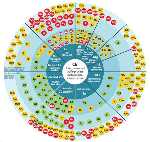
Key
Economically viable destinations of complex resources and materials, designed functional material combinations, scrap, residues, etc., to metallurgical processing infrastructure (each segment) to produce refined metals, high-quality compounds, and alloys in the best available technology.
Mainly recovered element
Compatible with the base metal as an alloying element or can be recovered in subsequent processing.
Recovered in alloy/compound or lost if in the incorrect stream/scrap/module
Governed by functionality, if not detrimental to base metal or product (e.g., if refractory metals in End-of-life product report to slag, and slag is also intermediate product for cement).
Mainly lost element: not always compatible with base metal or product
Detrimental to properties and cannot be economically recovered; e.g., Au dissolved in steel or aluminium will be lost.

CE's agile base metal processing infrastructure
Extractive metallurgy's backbone, the enabler of a CE as it also recovers technology elements used, e.g., in renewable energy infrastructure, internet of things, and eMobility, etc.

Dissolves primarily in base metal if metallic (mainly pyrometallurgy and smelting route)
Valuable elements recovered or dissipatively lost (metallic, speiss, compounds, and alloys in end-of life materials also determine the destination). Linked hydro- and pyrometallurgical infrastructure determines percent recovery.

Compound primarily to dust, slime, spelss (mainly hydrometallurgy and refining route)
Collectors of valuable minor elements as, e.g. oxides, sulfates, and chlorides, and mainly recovered in appropriate predominantly hydrometallurgical infrastructure if economical. Often separate infrastructure.

Primarily lost to benign, lower-value building material products; also contributing to disspative loss
Relatively lower value but an inevitable part of society and material processing. A sink for metals and loss from the CE system as oxides/compounds. Usually linked but separate infrastructure.
of metals and alloys (Reuter et al., 2019)
slags not only results in the potential loss of valuable components, but naturally creates long-term environmental challenges due to the presence of potentially toxic pollutants. Dissolution and/or desorption of the contained metal contaminants from landfilled slags invariably results in the transference of toxic metal ions into natural ecosystems, a phenomenon that results in bioaccumulation and biomagnification of toxins in terrestrial and aquatic ecosystems (Hudson-Edwards et al., 2011; Matinde et al., 2018; Piatak et al., 2021). Owing to high ecotoxicity of potential metal toxicants contained in most industrial slags, it is therefore counterintuitive to assume a business-as-usual approach when accounting for the environmental impact of metal production processes (Adhikari et al., 2022; Hudson-Edwards et al., 2011; Lottermoser, 2011; Piatak et al., 2015; Rieger et al., 2021).
This paper provides an overview of properties and crystallization behaviour of typical metallurgical slags. It expands on previous studies on the production and valorization of industrial slags (Matinde et al., 2018; Matinde and Steenkamp, 2021). The first part of this review paper provides an overview of the categories of bulk and commonly problematic complex slags, including the major phases formed during the solidification process under conventional conditions. The second part briefly explores the potential application of magnetic fields, commonly referred to as magnetohydrodynamic (MHD) conditions, to the industrial processing of metallic and other oxide melts. Although not yet tested on oxide systems, the last part of the paper extrapolates the transversal application of MHD to controlling the crystallization behaviour of bulk transition metal-bearing slags.
This paper employs a critical review approach to assess, evaluate, and analyse multiple literature sources on the solidification and crystallization behaviour of complex transition-metal-bearing slags. Critical reviews integrate findings and perspective from multiple literature sources, provide the opportunity to generate new knowledge, advance transversal applications of existing knowledge, and uncover new areas in which more research is needed (Snyder, 2019; Torraco, 2005). The review process adopted in this study relies on scientific journal articles, reports, and conference proceedings accessed from open access databases such as Google Scholar, Web of Science, Scopus, and SciFinder. The subject on the production and properties of metallurgical slags is mature and broad, so this author deliberately assumed general knowledge on the specific or individual industrial processes producing the slags.
The different categories of industrial slags were selected based on a combination of several criteria. These included the industrial and economic importance of the metal/alloy/matte products, volume of slag produced per unit product, and potential environmental potency when discarded into the environment. Special attention was given to the crystallization behaviour of bulk transition-metal-bearing industrial slags; namely, steelmaking slags, ferroalloy slags, base metal converting slags, and/or other categories of slags containing entrained and/or dissolved transition metal elements.
From the broad criteria, the following key words and/or their combinations guided the literature search: slag composition, slag cooling rate, spinel phases, solidification and crystallization behaviour, slag reclamation, environmental toxicity, phase stabilization. Literature search on the potential application of MHD to the crystallization behaviour of transition metal-bearing
slags used the following key words: magnetic properties, electrical conductivity, ferrites, magnetic field strength, electromagnetic field, and magnetohydrodynamic behaviour.
Production and properties of slags: An overview
Metallurgical slags are solid by-products produced in the smelting and refining of metals, mattes, and alloys. They are formed from the reaction between fluxes and gangue minerals in raw materials charged into smelting furnaces or from the reaction between fluxes and dissolved impurities during the refining stage (Gaskell, 2007). Broadly, slags can be categorized into ferrous, ferroalloys, and nonferrous slags (Luo and He, 2021; Matinde and Steenkamp, 2021). Ferrous slags are produced in the smelting and refining of iron and steel products, and predominantly belong to the CaOSiO2-Al2O3-MgO-FeO slag system. Ferroalloys slags are produced from the production of bulk and minor ferroalloys and mainly consist of SiO2, MgO, and Al2O3. Nonferrous slags are produced from the smelting and refining of nonferrous metals from their natural ores and/or secondary resources, and broadly belong to the FeO-SiO2-Al2O3-CaO systems. Fundamental knowledge of the unit processes producing the slags unlocks the understanding of phase chemical properties and, ultimately, the valorization potential of the discard slags (Piatak et al., 2021).
Metallurgical slags considered in this review include, but are not limited to, high-volume industrial slag systems, such as stainless steel slags, ferrochrome (FeCr) slags, ferromanganese (FeMn) slags, ferronickel slags (FeNi), base metal slags, and/or other categories of slags containing entrained and/or dissolved potentially toxic metal elements. In addition to the high value of metals and metalloids present, these slags constitute some of the most problematic industrial emissions due to the presence of potent metal pollutants such as Cr, Mn, V, Ni, Zn, Pb, among others (Gu et al., 2021; Holappa et al., 2021; Pan et al., 2019; Piatak et al., 2021). Rare earth oxide-bearing slags were also considered due to their potential economic value and significance to South Africa.
Ironmaking and steelmaking slags
Global crude steel production surpassed 1.8 Bt in 2023 (WorldSteel, 2024). Most of the steel products consumed are produced via two main routes; namely, the integrated blast furnace basic oxygen (BFBOF) and electric arc furnace routes. The BF-BOF route is the most dominant process, accounting for close to 75% of global crude steel production. The volumes and physicochemical properties of the slags produced in each process are strongly dependent on the unit process in which they are generated, the quality of raw materials used, quality and type of product produced, and the type of fluxes (Gu et al., 2021; Holappa et al., 2021; Luo and He, 2021). Figure 2 shows the integrated process used in the production of iron and steel products (Luo and He, 2021).
Stainless steel is a ubiquitous industrial material, with a compound annual growth rate averaging 5% from 1980 to date (Gu et al., 2021; Holappa et al., 2021; Luo and He, 2021; Ndlovu et al., 2017). The global production of stainless steel surpassed 52 Mt in 2022, resulting in the production rate of slags in the range 15−17 Mt/a from unit processes such as electric arc furnace (EAF), argon-oxygen decarburization (AOD), and ladle furnace (LF) refining (Figure 3) (Gu et al., 2021; Holappa et al., 2021). The volumes and chemical properties of stainless steelmaking slags vary significantly, and are dependent on, among other factors, the process in which they are generated, the quality of raw materials, and the type of alloy produced. Compared with the production of

Slag
Slag rate: 60-270 kg/t steel
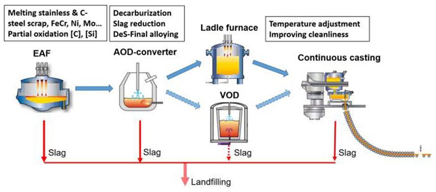
other alloys and metals, the production of stainless steel products is associated with large volumes of slags containing significant amounts of potentially problematic heavy metal contaminants (Gu et al., 2021; Holappa et al., 2021; Luo and He, 2021; Seetharaman et al., 2022).
Depending on the type of steel or alloy produced, steelmaking slags contain significant amount of dissolved and/or entrained alloying elements such as Cr, Ni, Mn, Mo, and V. Amongst these, Cr is the most important and abundantly used alloying element due to its unique corrosion resistance property. Stainless steels contain a minimum of 10.5 mass% Cr and up to 18 mass% Cr. Chromium is not only an indispensable alloying element in stainless steels, but it is also one of the most problematic toxic metal contaminants present in discard slags (Gu et al., 2021; Holappa et al., 2021). By nature, stainless steel slags inherently contain significant amounts of Cr, ranging between 3 7 mass% Cr2O3 and 1 3 mass% Cr2O3
for EAF and AOD slags, respectively (Gu et al., 2021; Holappa et al., 2021; Huo et al., 2023; Jung and Sohn, 2014a; Kim and Sohn, 2023; Li et al., 2023; Liu et al., 2022; Luo and He, 2021; Matinde et al., 2018). Cr in solidified discard slags can exist in different forms and oxidation states, most notably as oxides dissolved in slag, as stable spinel phases such as (Mg,Mn)(Cr,Al,Fe)2O4, FeCr2O4, or Mg(Al,Cr)2O4, among others, as entrained elemental Cr, or as Cr in solid solution with other transition metal elements (Gu et al., 2021; Holappa et al., 2021; Huo et al., 2023; Jung and Sohn, 2014a; Kim and Sohn, 2023; Li et al., 2023; Liu et al., 2022; Matinde et al., 2018).
Stainless steel slags also contain significant amount of CaO, SiO2, MgO, and CaF2, which, like other forms of industrial wastes, can be considered as secondary resources in the construction industry. However, Cr-bearing slags are considered hazardous solid waste in many jurisdictions, and this severely constrains and limits their applications in transversal industries. In as much as most
of the Cr dissolved in slag deports to stable spinel phases in the trivalent (+3) state and has limited mobility in the environment, the transformation of the stable +3 state to the unstable hexavalent (+6) state is thermodynamically feasible under certain environmental conditions (Apte et al., 2006; Ball and Nordstrom, 1998; Barnhart, 1997). In the hexavalent state, Cr is highly toxic, soluble in water and highly mobile in the environment, and is considered to be one of the most potent mutagenic, carcinogenic and teratogenic agents known to humanity (Apte et al., 2006; Barnhart, 1997; Ščančar and Milačič, 2014). The non-biodegradability of hexavalent Cr species presents long-term ecological risks due to their persistence and bioaccumulation in the environment (Apte et al., 2006; Barnhart, 1997; Ščančar and Milačič, 2014).
Owing to the prevalence of potentially toxic elements in typical stainless steel slags, understanding their crystallization behaviour has always been a top priority for the global steel industry, both from metal recovery and environmental performance points of view. Although stainless steel slags can be considered as secondary sources of valuable Cr, Ni, Mn, and Mo units, among others, their recovery efficiencies are characteristically low and normally dictated by the state in which the metal-bearing phases crystallize in the solidified slag. The challenges in predicting the solidification phases, due to poor understanding of the solidification mechanisms, and the phases formed therefrom, are well documented where they are shown to be a barrier to increasing the valorization potential of these slags. A number of recent studies have been devoted to addressing this gap, most have focused more particularly on understanding selective crystallization of the metal-enriched phases during the slag solidification process in order to enhance their separation from the metal-depleted slag phases (Gu et al., 2021; Holappa et al., 2021; Huo et al., 2023; Jung and Sohn, 2014a; Kim and Sohn, 2023; Li et al., 2023; Liu et al., 2022; Matinde et al., 2018).
Ferroalloys slags
Ferroalloys refer to various alloys of iron with a high proportion of one or more other elements such as Cr, Mn, and Si (Eric, 2014; Matinde and Steenkamp, 2021). Ferroalloys are classified as major or bulk ferroalloys, such as ferrochromium (FeCr), ferromanganese (FeMn), silicomanganese (SiMn), ferrosilicon (FeSi), and ferronickel (FeNi), and minor ferroalloys such as ferrotitanium (FeTi), and ferroniobium (FeNb), among others. Bulk ferroalloys are produced in large quantities using EAF (Eric, 2014; Hayes, 2004; Matinde and Steenkamp, 2021). Approximately 85%−95% of bulk ferroalloys are used in the steelmaking industry due to their unique alloying properties.
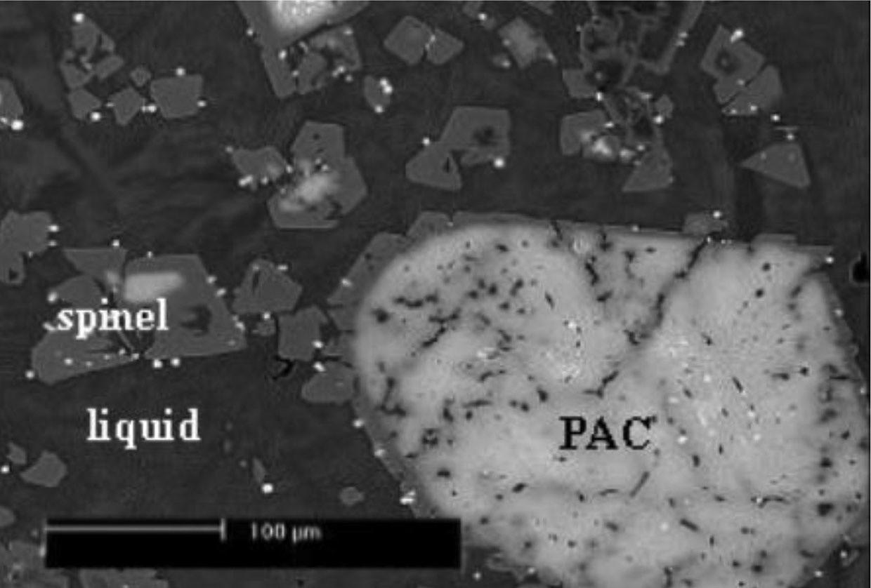
Ferrochromium alloys are indispensable ingredients in the production of various grades of stainless steel alloys. They are produced from the carbothermic reduction of beneficiated chromite concentrates in submerged arc (SAF) or direct current (DC) arc furnaces. About 6 Mt of FeCr slags are produced globally, corresponding to about 1.1−1.6 tonnes of slag per tonne of FeCr alloy (Niemelä and Kauppi, 2007). Depending on the type of raw materials and process control philosophy, FeCr slags naturally contain elevated amounts of residual Cr, often in the range 1.8−8.7 mass% Cr2O3 (Harman and Rao, 2013; Hayes, 2004; Matinde and Steenkamp, 2021; Niemelä and Kauppi, 2007). The Cr in solidified FeCr slags can also occur as partially altered chromites (PAC), chromites (Cr2O3) dissolved in slag, Cr alloy phases dispersed in slag (Holappa and Xiao, 2004; Panda et al., 2013), as well as Cr bound in (Mg,Fe)/(Fe, Al, Cr)2O4 or FeCr2O4 spinel phases (Li et al., 2013; Samada et al., 2011). Tanskanen and
Makonnen (2007) confirmed that the phases in air-cooled industrial FeCr slags consist of partly crystalline and hypidiomorphic spinel ((Mg,Fe)/(Fe,Al,Cr)2O4), forsterite (Mg2SiO4), and pyroxene (Mg2(Cr,Al,Si)2O6) crystals enclosed in a condensed and homogenous glass matrix (Figure 4a). Hayes (2004) investigated the microstructure of slow cooled FeCr slags and identified the presence of PAC phases co-existing with precipitated secondary spinels (Figure 4b). The phase composition of FeCr slags is strongly dependent on the chemical composition and cooling characteristics and/or their olidification pattern of the slags, understanding their crystallization and solidification behaviour therefore provides an entry point to understanding the speciation and recoverability of Cr from industrial FeCr slags (Harman and Rao, 2013; Hayes, 2004; Li et al., 2013; Matinde et al., 2018; Niemelä and Kauppi, 2007; Samada et al., 2011; Tanskanen and Makkonen, 2007).
Ferromanganese alloys are produced by the carbothermic reduction of lumpy or sintered Mn ores in three-phase SAF (Eric, 2014; Olsen et al., 2007; Tangstad, 2013). Discard FeMn slag typically contains 8−12 mass% MnO, with major oxides being CaO (approx. 35 mass%), SiO2 (approx. 24 mass%), Al2O3 (approx. 21 mass%), and MgO (approx. 5 mass%) (Olsen et al., 2007;

Steenkamp and Basson, 2013; Tangstad, 2013). The typical phase compositions of slow-cooled FeMn slags include gehlenite (Ca2Al(AlSiO7)), glaucochroite (CaMnSiO4), manganosite ((Mn,Mg,Ca)O), and spinel ((Mn,Mg)Al2O3)) (Groot et al., 2013; Norval and Oberholster, 2011; Steenkamp et al., 2011; Zhao et al., 2005).
Over 20 Mt of FeMn slags have accumulated in slag dumps in South Africa, and a further 0.5 Mt are estimated to be added every year (Groot et al., 2013). To date, efforts have been directed in developing alternative processes and technologies, not only to recover the entrained alloys before disposal, but also for enhancing the in-process recycling and reuse of the slags in alternative industries (Groot et al., 2013; Norval and Oberholster, 2011).
According to Westfall et al. (2016), FeMn slags can be directly reprocessed within the Mn production process for their Mn content, or can be used as a low cost material for local building and road construction. Based on a global lifecycle study of Mn alloys and Mn by-products, approximately 530 kg slag/t Mn-alloy is sold to the construction industry, 360 kg slag/t Mn-alloy is recovered in furnaces, while approx. 140 kg slag/t Mn-alloy is stockpiled (Westfall et al., 2016). In South Africa, for example, the remote locations of most Mn smelters suggest that most of Mn-slags will have little economic value and are thus typically stockpiled at or near the smelters.
Ferronickel represents an irreplaceable alloying additive for stainless steels, for nickel-based super alloy, electroplating, and for other types of special steels. These alloys are produced from the reductive smelting of roasted limonite (containing approx. 45−50 mass% Fe and 1.2−1.3 mass% Ni) and saprolitic ores containing approx. 15−20 mass% Fe and 2.0−2.3 mass% Ni in electric furnaces (Keskinkilic, 2019; Polyakov, 2013; Sagadin et al., 2016). Depending on the quality of starting materials, slags produced from a typical FeNi process belong to the FeOSiO2-Al2O3-MgO system and comprise of 35−70 mass% SiO2, 15−45 mass% MgO and 5−35 mass% Fe2O3 as the main oxides (Sagadin et al., 2016). The slag rate is also significant, at approx. 650−700 kg/t crude FeNi (Polyakov, 2013; Sagadin et al., 2016). Over time, the volume of slags produced from the production of FeNi alloys is expected increase significantly due to the increase in global installed capacity of FeNi smelters utilizing lower grade limonitic and/or saprolitic ores (Keskinkilic, 2019).
Base metal slags
Base metals commonly refer to industrial metals such as Cu, Ni, Co, Pb and Zn. These metals predominantly occur naturally combined with Fe and S in complex polymineralic and polymetallic sulfide systems, such as Cu-Fe-S, Fe-Ni-S, Cu-Pb-Zn-Fe-S, Zn-Pb-Fe-S, and Cu-Ni-Co-Fe-S systems (Ndlovu et al., 2017; Rankin, 2011; Schlesinger et al., 2011; Warner et al., 2007). Sulfide ores are invariably associated with Fe- bearing minerals such as pyrrhotite (Fe1-xS) and/or pyrite (FeS2), and, as such, slags from the smelting and converting of such polymetallic ores or concentrates tend to contain significant amounts of iron oxides (Moats and Davenport, 2014; Schlesinger et al., 2011; Sohn, 2014; Suh et al., 1988; Warner et al., 2007).
With the exception of Zn and Pb, the pyrometallurgical processing of base metals involves two separate processes; the electrothermal smelting of sulfide concentrates to produce metalenriched sulfide matte followed by converting by blowing oxygen into the matte to oxidize the Fe and S impurities. The turbulent and highly oxidizing conditions in standard industrial converters
invariably result in significant losses of the base metals, both as entrained matte and as oxides dissolved in slags (Jones, 1999, 2005; Nagamori, 1974; Nell, 2004). Because of the high Fe-oxide content inherent in base metal slags, controlling the slag chemistry is important to reduce the precipitation of spinel oxide phases such as Fe3O4 (can typically be in the range 15−40 mass%) to acceptable levels (Jak et al., 2008; Kleeberg, 2022; Schlesinger et al., 2011).
Base metal converter slags are normally recycled back into primary smelting units or are granulated and processed to recover values by physical and chemical beneficiation methods. Depending on installed capacity, the values contained in slags can also be recovered by re-melting and settling in specially designed EAF (Jones, 1999, 2005; Jones, 2004; Toscano and Utigard, 2003). However, the recyclability of some base metal slags is constrained by the presence of adverse slag constituents such as Cr2O3 and MgO (Jones, 2005; Nell, 2004). For example, slags from the smelting and converting of platinum group metal (PGM) concentrates, particularly those from the UG2 deposit in the Bushveld Complex in South Africa, contain elevated amounts of Cr2O3 (approx. > 1.2 mass% Cr2O3) and pyroxenite gangue (MgO), leading to the formation of spinel phases, such as (Fe,Mg) Cr2O4, in the process (Jones, 1999; Kleeberg, 2022; Nell, 2004). Gabasiane et al. (2021) also confirmed the formation of Cu - and Ni - containing spinel phases, mainly as FeCr2O4, (Co,Fe) CrO4 and (Mg,Fe)2SiO4, from Cu-Ni slags produced at the BCL Selebi-Phikwe smelter in Botswana. As such, the in-process recycling of converter slags inevitably increases the cycling and build-up of high melting point spinel phases in the process (Jones, 1999; Kleeberg, 2022; Nell, 2004).
Significant amounts of Pb slags are produced from primary and secondary production of Pb from concentrates and recycled materials, respectively. Primary lead slags are produced by smelting of sulfide concentrates via the sinter-blast furnace and direct smelting routes (Ettler and Johan, 2014; Ettler et al., 2009; Pan et al., 2019; Yin et al., 2016; Zhang et al., 2016). The chemical composition and phase properties of primary Pb slags vary greatly, depending on the quality of ores and fluxes, as well as the level of impurities in reductants like coke. More recently, secondary lead from recycling processes has become a major source of lead, with approximately 100−350 kg of Pb secondary slag being produced for every tonne of metallic lead (Pan et al., 2019; Zhang et al., 2016). The contents of oxides in both primary and secondary Pb slags exhibit significant variability, but are characterized by elevated amounts of FeO, SiO2, Al2O3, CaO, MgO, ZnO, and PbO. Typical phases such slags consist of complex oxides rich in iron, such as FeO, and Fe2SiO4, co-existing with solid solutions and/or spinel phases such as Fe3O4, ZnFe2O4, (Fe,Zn)O∙(Al,Fe)2O3, and (Ca2(Fe,Mg,Zn,Al)(Si,Al)2O7 (Ettler and Johan, 2014; Ettler et al., 2009; Kleeberg, 2022; Pan et al., 2019; Yin et al., 2016). Although the spinel phases are presumed to be geochemically inert over long periods of time, Ettler et al. (2009) investigated the mineralogical properties of historical Pb-Zn slags from Tsumeb smelter and observed the presence of Pb-rich felspar (PbAl2Si2O8) crystals and spinel phases ((Zn,Mg,Fe,Cu) (Fe,Al)2O4) co-existing with potentially active Ca-Pb arsenate ((Pb,Ca,Fe)3(AsO4)2∙H2O) as well as spinel ((Zn,Mg,Fe,Cu) (Fe,Al)2O4) in olivine phases. The different phases will invariably affect the long-term geochemical and envrionmental performance of the slags, albeit being produced from the same unit process.
Rare earth oxide (REO)-bearing slags
Rare earth elements (REE) are considered critical due to their
unique and irreplaceable electrochemical, optic, catalytic, magnetic, alloying, and thermal properties (Ganguli and Cook, 2018; Maluleke et al., 2020; Walters et al., 2011). REE do not exist as individual native metals, but instead are lithophilic elements that occur together in numerous ores or accessory minerals and rocks, including as halides, silicates, oxides, phosphates, and carbonates (Balaram, 2019; Faris et al., 2019; Walters et al., 2011). These minerals often contain different REE combinations as the REEs are sometimes interchangeable with each other due to similar ionic chemistries (Balaram, 2019; Walters et al., 2011). Over 95% of the REE are reported to occur in three minerals: bastnäsite, monazite, and xenotime. Bastnäsite is the most abundant of the REE mineral ores and is most commonly found in carbonate-silicate rocks occurring with and related to alkaline intrusions (Balaram, 2019; Walters et al., 2011). Due to the exponential increase in the global demand for REE, coupled by the desire to develop alternative supply chains outside China, there is increasing need to exploit lower grade and more complex REE deposits, especially those hosted in ferruginous ores (Bisaka et al., 2017; Faris et al., 2017; Faris et al., 2019).
The REE in complex ferruginous REE-bearing ores, such as the Zandkopsdrift carbonatites (South Africa), Bayan Obo carbonatite-dolomitic deposit (China), and Olympic Dam iron oxide-copper- gold deposits (Australia), occur as discretely and finely disseminated inclusions in Fe-rich gangue, thereby making this difficult and expensive to recover by conventional physical and chemical beneficiation methods (Bisaka et al., 2017; Faris et al., 2017; Faris et al., 2019; She, Yi, et al., 2020). Such ores require multiprocess approaches that include a combination of pyrometallurgical and hydrometallurgical processing steps to reduce the amount of ferruginous gangue and reduce reagent consumption rates.
Bisaka et al. (2017) proposed a process to recover REE from complex iron oxide-bearing ores using direct carbothermic smelting of ferruginous REE ores to produce pig iron and REO-rich slag (Bisaka and Thobadi, 2019; Bisaka et al., 2017). The process not only recovers iron as a saleable product, but also results in the concentration and homogenization of the REO in slag phases that are amenable to leaching using conventional inorganic acids (Bisaka and Thobadi, 2019; Bisaka et al., 2017). Notwithstanding the potential impact of this process, extensive studies conducted by the authors indicate that, depending on the composition of the ore, the REO slags produced exhibited different downstream REE leaching efficiencies, albeit produced under the same smelting and furnace operating conditions (Bisaka and Thobadi, 2019; Bisaka et al., 2017). Phase characterization of the PyEarth™ slags produced from various sources indicated that more than 90% recovery of mixed REO can be achieved from slags that exhibited a high deportment of REO in labile silicate phases, compared with less than 50% recovery from slags with significant proportion of refractory perovskite (CaTiO3) phases (Bisaka et al., 2017). According to Bisaka et al. (2017), the REO in slags preferentially deport to the refractory perovskite phases, as opposed to the more labile silicate phases (Bisaka and Thobadi, 2019; Bisaka et al., 2017).
The recovery of REO from slags produced from the direct smelting of complex REE ores is complicated by their tendency to deport to refractory oxides in slags (Bisaka and Thobadi, 2019; Bisaka et al., 2017; She, Yi, et al., 2020). The presence of FeO and MnO in REO slags was, however, observed to suppress the crystallization of perovskite phases (Bisaka and Thobadi, 2019; Bisaka et al., 2017; Goldschmidt and Rait, 1943; Kang and Lee, 2005a, 2005b; Sadykhov and Karyazin, 2007). In particular,
the presence of MnO in slags results in the formation of labile pyrophanite (MnTiO3) phases, which, in essence, suppress the perovskite formation by depleting the mass fraction of the TiO2 available. (Kang and Lee 2005a) investigated phase equilibria in MnO-TiO2-Ti2O3 in the temperature range 1300°C to 1550°C. The findings indicate that the main phases include molten oxide, manganosite (MnO), rutile (TiO2), spinel (Mn2TiO4-MnTi2O4), pyrophanite (MnTiO3-Ti2O3), and psuedobrookite (MnTi2O5Ti3O5) solid solution. Sadykhov and Karyazin (2007) also observed that the presence of MnTiO3 suppressed precipitation of CaTiO3 and FeTiO3 solid solutions during the crystallization of titaniferous magnetite slags containing approx. 6 mass% MnO. Similarly, the presence of FeO in slag was observed to favour the precipitation of the ulvospinel phase, Fe2TiO4, as opposed to the perovskite phases (Sadykhov and Karyazin, 2007), thereby highlighting the potential for mitigating the formation of refractory perovskite phases by controlling the slag chemistry, in particular the CaO and FeO/ MnO ratios, during the solidification process (Kang and Lee, 2005b; Sadykhov and Karyazin, 2007). Findings from other studies also indicate that controlling the chemical composition and cooling process can result in crystallization and enrichment of otherwise dispersed REE into desired REO-bearing phases, thereby enabling their recovery from labile slag phases (Ding et al., 2013; Lan et al., 2020; Le et al., 2016; Li et al., 2005; She, An, et al., 2020).
Slags naturally contain appreciable amounts of dissolved and/or entrained metals, mattes, and alloys, so slag dumps are regarded as potential sources of valuable resources (Gu et al., 2021; Kim and Sohn, 2023; Kukurugya et al., 2020; Matinde et al., 2018; Potysz and van Hullebusch, 2021; Wang et al., 2017; Wang and Sohn, 2019). The reclamation of slag dumps to recover valuable metals, alloys, and mattes is not a new practice. Several processes have been developed over the years that economically reclaim the valuable components from slag dumps, albeit with varying degrees of success and impact. The processes to recover valuable components from slags can be split into three generic categories, namely; physical beneficiation, hydrometallurgical, and pyrometallurgical processes (Gu et al., 2021; Kim and Sohn, 2023; Matinde et al., 2018). Depending on the type of slag and/or type of valuable component to be recovered, these processes can be applied singly or in combination with one another.
Physical beneficiation processes are applicable to a wide variety of slag types and are probably the most popular approach due to their simplicity and low cost. However, these processes have inherent limitations, such as low efficiency and the need for fine milling to liberate the valuable components from the bulk slag (Bai et al., 2015; Shen and Forssberg, 2003; Sripriya and Murty, 2005). Physical beneficiation methods are also potentially problematic in recovering components dissolved in congruous slag phases, especially those associated with fine dissemination of the desired components within the various slag phases (Shen and Forssberg, 2003; Sripriya and Murty, 2005). Pyrometallurgical processes, although highly effective, are costly, highly energy intensive, have a high carbon footprint, and are marginally economic for treating large volumes of slags containing relatively low concentration of valuable components (Gu et al., 2021; Jones et al., 1998; Maeda et al., 1981; Shen and Forssberg, 2003; Shibata et al., 2002). Although hydrometallurgical processes may require lower setup and operational costs than pyrometallurgical processes, such processes are usually associated with high reagent consumption
and low reaction kinetics, especially when operated under ambient conditions. The complex chemical and phase-chemical properties typical of most solidified slags, coupled with the complexities of handling and disposing the leach residues and spent solutions, negates the widespread adoption of some of the commercially feasible processes (Groot et al., 2013; Gu et al., 2021; Matinde et al., 2018).
State of the art and search for new research agenda
Environmental challenges associated with uncontrolled disposal of slags, coupled with the constraints associated with conventional metal recovery processes clearly dictate the need to explore new approaches to enhance downstream recoverability of valuable components from bulk slags by simple means. Poor phase separation and fine dissemination of the desired components within the various slag phases are widely cited as key challenges limiting the recoverability of values from slags by conventional beneficiation methods (Gu et al., 2021; Matinde et al., 2018; Piatak et al., 2021; Shen and Forssberg, 2003). This means that any deliberate attempt to improve phase separation and concentrate the contained metal values in labile phases can significantly increase the recoverability of the valuable components while concurrently developing a barren slag compatible with alternative reuse options. In other words, controlling the crystallization behaviour ex-ante can be considered a pragmatic approach to enhance the holistic valorization of complex industrial slags.
Applications of slags as cement additives
Cementious properties of metallurgical slags and their applications as construction aggregates are widely documented (Jiang et al., 2018; Kim et al., 2015; Ryu et al., 2024). The high CaO content in steelmaking slags, for example, makes them ideal replacements for limestone in the clinker process, however, their use is constrained by the presence of potentially toxic elements such as Fe (as residual FeO), and Cr, Mn, Ni, and P, among others (Gu et al., 2021; Kim and Sohn, 2023; Li et al., 2020; Matinde et al., 2018; Ndlovu et al., 2017; Piatak et al., 2015; Piatak et al., 2021; Rieger et al., 2021; Wang and Sohn, 2019). The recovery of Fe and other metals contained in the slag, coupled with intentional fluxing and conditioning of the slag to meet the requirements of the downstream industries, can significantly improve the economics and environmental performance of metallurgical slags. In particular, the application of steelmaking slags as cement additives is a potential game-changer towards developing high-performance and ultra-low carbon cement clinkers.
Slag microstructure conditioning to enhance metal recovery
Engineering slag properties by optimising their structure and properties to their post-furnace applications is a pragmatic approach to increasing the industrial ecology of smelters. To date, controlled crystallization and microstructure conditioning to concentrate valuable components in labile slag phases have been acknowledged as simple and yet pragmatic approaches to enhancing the recoverability of valuable components from complex slags before disposal (Li et al., 2019; Ma et al., 2017; Ma et al., 2019; Semykina et al., 2010; Semykina et al., 2011; Shatokha et al., 2013; She, et al., 2020; Sui et al., 2003). Previous studies extensively explored the crystallization behaviour of transition metal-bearing slags under different solidification conditions and concluded that transition metal-bearing phases with desired properties can be engineered and maintained during the solidification process to
enhance their separation from the bulk slag phases (Diao et al., 2016; Ding et al., 2021; Fan et al., 2014; Jung and Sohn, 2014a; Kim and Sohn, 2023; Li et al., 2023; Ma et al., 2017; Mondy, 1872; Semykina et al., 2010; Semykina et al., 2011; Shatokha et al., 2013). For example, ferrite phases (MFe2O4, where M = Fe, Mn, Cr, Ni, Cu, Co, Zn, Ti, La, etc.) with high magnetic signatures can be produced and maintained during the solidification process to enable their complete separation by coarse milling and magnetic separation techniques (Jung and Sohn, 2014a; Kim and Sohn, 2023; Li et al., 2020; Li et al., 2023; Liu et al., 2022; Semykina et al., 2010; Semykina et al., 2011; Shatokha et al., 2013). Specific ferrite phases, such as MnFe2O4 and Fe3O4, possess interesting magnetic properties that can potentially be exploited in their magnetic separation from bulk non-magnetic silicate components of the slags (Ding et al., 1997; Liu et al., 2022; Sugimoto, 1999). This means that the magnetic properties, engineered at crystal level, could be exploited in magnetic recovery of transition metal-bearing components in the non-magnetic bulk slags (Ding et al., 1997; Liu et al., 2022; Semykina et al., 2010; Semykina et al., 2011; Shatokha et al., 2013; Sugimoto, 1999).
The competitive crystallization and growth rate of crystals in complex slag systems is dominated by spinel and ferrite slag phases (Diao et al., 2016; Ding et al., 2021; Jung and Sohn, 2014b; Kim and Sohn, 2023; Li et al., 2020; Liu et al., 2022). Controlling crystallization parameters, such as cooling rate and chemical composition, has a significant impact on the competitive crystallization and growth of spinel and ferrite phases with high magnetic susceptibilities (Diao et al., 2016; Liu et al., 2022). The types, volume fraction, and distribution of crystals is strongly linked to the composition of the slags and cooling conditions (Diao et al., 2016; Ding et al., 2021; Jung and Sohn, 2014b). Competitive growth of crystals in complex slags results in preferential formation of high melting points and magnetically conducting spinels/ferrites in a non-conducting barren slag mass (Diao et al., 2016; Liu et al., 2022).
Diao et al. (2016) investigated the crystallization behaviour of complex vanadium- chromium slag systems under different heat treatment conditions. Based on crystal distribution theory, the authors developed a mathematical model to describe the competitive growth of crystals in a complex V-Cr slag system containing 11 mass% V2O3, 16 mass% Cr2O3, 15 mass% SiO2, 6 mass% TiO2, 4 mass% MgO, 24 mass% FeO and 6 mass% MnO. The confirmed slag phases consisted mainly of spinel [(Fe,Mg,Mn) (V,Cr)2O4, [(Fe,Mg)2TiO4] olivine [(Fe,Mg)2SiO4], and diopside [Ca(Fe,Al)2SiO6]. The results indicated that the crystallization rates of spinels, olivines, and augites were dominated by the slag component with the highest melting point and that these followed the sequence FeCr2O4 > Mg2SiO4 > FeV2O4 > MgSiO3 >FeTiO4 > Mn2SiO4 > MnSiO3 > Fe2SiO4, with the optimum temperature ranges for the crystallization of eminent phases such as FeCr2O4, FeV2O4, FeTiO4, and Fe2SiO4 in the order of 1224−1274ºC, 1028−1078ºC, 825−875ºC, and 712−762ºC, respectively (Diao et al., 2016).
Li et al. (2023) investigated competitive crystallization, in situ separation, and the solidification mechanism of Cr-spinel crystals from of Cr-bearing slags. The authors investigated the mechanism of competitive crystallization behaviour of Cr in the Cr-spinel by the substitution of Fe and Mn, followed by in situ separation using supergravity. The crystallization tendency of Cr to the Cr-spinel was enhanced by the substitution of Fe and Mn and this was
prevalent in the mole ratio (Cr+Al)/(Fe+Mn) ≈ 2.0 in the AB2O4 structure. Crystallographic characterization also confirmed the selective crystallization of high purity Cr-spinels containing c.a. 61 mass% Cr2O3. In a similar study, Yu et al. (2023) investigated the selective solidification behaviour of Cr into Cr-spinel as a function of MgO (mass%) content, followed by the subsequent separation of Cr-spinels from the liquid slag using super gravity. High-purity Crspinels with the chemical formula ((Mg,Fe,Mn)(Cr,Al)2O4) were recovered from the molten slag, with the Cr2O3 content of 58 mass% and Cr recovery rate of 88.6 mass%, where the MgO content increased from 2 mass% to 6 mass%. Further increase in the MgO content to 8 mass% resulted in the formation of the akermanite phase (Ca2MgSi2O7), which limited the solidification of Cr into the Cr-spinel. The findings from these studies confirm that intentionally controlling the crystallization behaviour of phases can be exploited and therefore can significantly improve the selective recovery of valuable elements such as Cr, V, Fe, and Ti from complex slags.
Findings from other studies have also demonstrated that most Cr in solidified stainless steel slags typically exists in primary spinel crystalline phases (Jung and Sohn, 2014a; Kim and Sohn, 2023; Li et al., 2020). The findings clearly indicate that Cr recovery can be enhanced by controlling the thermophysical properties of slags to intentionally influence the selective crystallization of Cr-phases (Jung and Sohn, 2014a; Kim and Sohn, 2023). Kim and Sohn (2023) investigated the effect of Cr2O3 content on the crystallization characteristics of CaO-SiO2-Al2O3-MgO-Cr2O3 slags as a function of cooling rate. The effect of Cr2O3 in the slag was two-fold: promoting the nucleation of crystalline phases by increasing the liquidus temperature and undercooling degree of the slag, and accelerating the diffusion kinetics of cations for crystallization by depolymerizing the network structure of the liquid slag. In an earlier study, Jung and Sohn (2014a) investigated the crystallization behaviour of FetO- rich CaO-SiO2-Al2O3-MgO slags in the basicity (CaO/SiO2) range of 0.7 to 1.08. At higher basicity, isothermal cooling at 1473 K resulted in the formation and growth of magnetic Fe-enriched spinel phases (e.g., MgAlFeO4) and nonmagnetic Fedepleted phases (e.g., Ca2MgSi2O7, Ca3MgSi2O8, and CaAlSi2O6) (Jung and Sohn, 2014a). The crystal phase controlled precipitation, which led to the separation of Fe-rich and Fe-depleted regions in the slag melt and, ultimately, in differences in the magnetic properties of the phases. This would thus be useful in the recovery of Fe-rich phases by magnetic separation (Jung and Sohn, 2014a). Similarly, Li et al. (2020) investigated the crystallization behaviour of modified EAF slag melts with unnormalized composition consisting of 23.5 mass% Fe2O3, 2.7 mass% Al2O3, 28.8 mass% SiO2, 32.3 mass% CaO, 5.0 mass% MgO, 2.4 mass% MnO, 1.1 mass% TiO2 and 0.1 mass% Cr2O3. The objective was to evaluate the precipitation and separation of value elements (e.g., Fe, Mg, Mn, Cr, Ti, and V) as magnetic spinels from a labile amorphous slag phase. By varying cooling rate and targeting crystallization temperatures followed by magnetic separation, the authors proposed that bulk spinel phases with primary phase ((Mn,Mg,Fe)(Fe,Al)2O4), size greater than 40 µm, and high magnetic susceptibility can be formed from the controlled crystallization of slags at basicity 1.2 (Li et al., 2020).
The use of strong magnetic fields has widely been used in the recovery of metals, mattes, and alloys from solidified slags (Asai, 1989, 2012; Davidson, 1999; Fautrelle et al., 2009; Jiles, 2015; Sun et
al., 2010; Svoboda and Fujita, 2003). Broadly, magnetic separation technologies exploit the different behaviours of materials when in an applied magnetic field. The magnetization force, F, that pulls ferromagnetic and paramagnetic materials to a magnetic field and repulses diamagnetic materials can be depicted as: , [1]
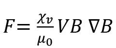
where χv is the dimensionless volumetric magnetic susceptibility of a particle, V is the volume of particle, μ0 is the magnetic susceptibility of vacuum, B is the external magnetic induction, and ∇B is magnetic field gradient of the magnetic induction (Asai, 1989, 2012; Davidson, 1999; Fautrelle et al., 2009; Jiles, 2015).
The magnetic properties of a material correspond directly to the crystal structure and electron configurations (Jiles, 2015; Jordens et al., 2014; Oberteuffer, 1974; Sun et al., 2010). In particular, the unpaired electrons in certain types of atoms cause magnetic dipoles, which lead to the creation of magnetic moments in a material. These magnetic moments can, in turn, result in a magnetic force on the material when aligned by an externally applied magnetic field. The higher the magnetic susceptibility of a material, the stronger the magnetic response to the imposed magnetic fields (Sun et al., 2010). Most commonly, the high magnetic susceptibility of compounds containing transition metals arises from the electronic properties of transition metal ions dominated by partly filled d-orbitals (Jiles, 2015; Jordens et al., 2014; Oberteuffer, 1974; Sun et al., 2010).
Magnetic properties are classified into three broad categories: ferromagnetic, paramagnetic, and diamagnetic (Jiles, 2015; Jordens et al., 2014; Oberteuffer, 1974; Sun et al., 2010). Ferromagnetic materials are those that exhibit strong magnetism along the lines of an applied magnetic field and will tend to stay magnetized to some extent after being subjected to an external magnetic field. Unlike ferromagnetic materials, the atomic moments of which exhibit very strong interactions with the applied magnetic field, paramagnetic materials are weakly attracted by an external applied magnetic field (Jordens et al., 2014; Sun et al., 2013). Paramagnetic materials have a permanent dipole moment due to unpaired electrons in partial field orbitals and, on applying an external magnetic field, the atomic dipole aligns in the direction of the applied external magnetic field (Jordens et al., 2014; Sun et al., 2013). Unlike ferromagnetic or paramagnetic materials that are attracted along the lines of an applied magnetic field, diamagnetic materials are composed of atoms with paired electron orbitals, they have no net magnetic moments, and are repelled along the magnetic field lines (Jiles, 2015; Jordens et al., 2014; Oberteuffer, 1974; Sun et al., 2010). The application of magnetic fields, commonly referred to as magnetohydrodynamic (MHD) processing in process and engineering metallurgy, is not new. Various forms of MHD principles have been widely adopted in the processing of conducting metallic melts, particularly in areas such as electro slag re-melting, homogenization of alloys, inclusion removal, and controlled solidification of metallic melts and alloys (Asai, 2012; Davidson, 1999; Fautrelle et al., 2009; Leenov and Kolin, 1954; Takahashi and Taniguchi, 2003; Zhang et al., 2014). Magnetohydrodynamic studies focus on the magnetic properties and behaviour of electrically conducting fluids such as plasmas, liquid metals, sea water, and electrolytes (Asai, 2012; Davidson, 1999; Fautrelle et al., 2009; Leenov and Kolin, 1954). Magnetohydrodynamic processing exploits the different behaviours of electrically conducting particles in an electromagnetic field, with different materials exhibiting different behaviours under static or transient magnetic fields. The
MHD behaviour of electrically conducting fluids is governed by a combination of Maxwell’s equations, Ohm’s law and Navier-Stokes equations on fluid flow in electric and magnetic fields. The fluid driving force is induced by imposing a direct electric current and a magnetic field, F = J × B or by imposing a travelling magnetic field (Asai, 2012; Davidson, 1999; Fautrelle et al., 2009; Leenov and Kolin, 1954; Ščepanskis and Jakovičs, 2016; Takahashi and Taniguchi, 2003; Zhang et al., 2014). In this case, J and B denote current density and magnetic flux, respectively.
Seminal work by Leenov and Kolin (1954) paved the way for the application of MHD to the control of non-metallic inclusions in conductive metallic melts at high temperatures. Leenov and Kolin (1954) proposed that an electrically neutral and non-magnetized particle with electric conductivity and magnetic permeability different from the properties of a liquid in which it is suspended experiences an electromagnetokinetic force when traversed by an electric current and transverse magnetic field. The authors computed the force imposed on an electrically neutral spherical non-metallic inclusion particle under gravitational separation and electromagnetic from a pool of conducting metal melt (Leenov and Kolin, 1954). The principle governing the electromagnetic separation of a non-conducting spherical particle in a conductive liquid under electromagnetic conditions is shown in Figure 5 (Zhang et al., 2014). When a uniform electromagnetic force is applied to a conductive liquid metal, the metal is compressed by the electromagnetic force and a pressure gradient is generated in the metal. The nonconductive particle suspended in the liquid metal does not experience the electromagnetic force and, as a result, it is forced to move in the opposite direction of the electromagnetic force. The force, FP, imposed on a non-conducting spherical particle in a conductive fluid traversed by a uniform electromagnetic force, is shown in Equation [1] (Leenov and Kolin, 1954; Ščepanskis and Jakovičs, 2016; Takahashi and Taniguchi, 2003; Zhang et al., 2014): , [2]
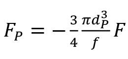
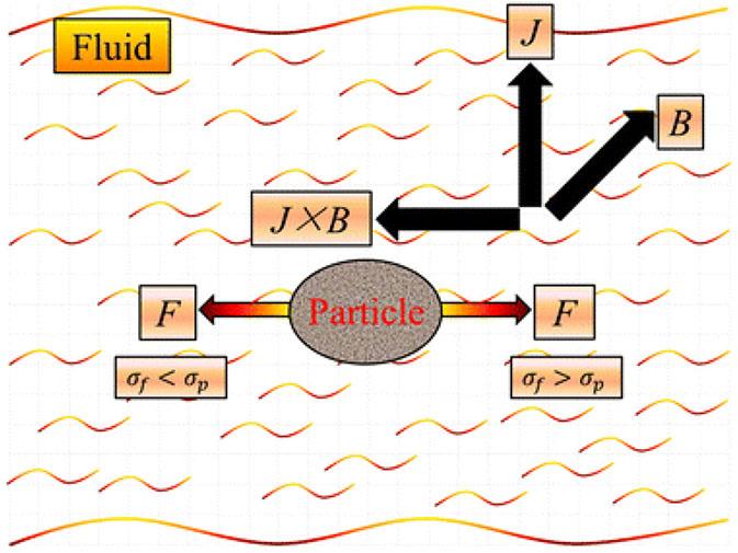
Figure 5—Electromagnetic forces on a spherical particle associated with a single particle in crossed electric and magnetic fields (Zhang et al., 2014). The direction of movement of the particle depends on the electrical conductivity difference between the fluid and the particle
where FP is the force acting on a particle, F is the imposed electromagnetic force, and d is the particle diameter. The electromagnetic force can be generated in three main ways: using a static magnetic field source (Figure 6a), a direct current electric field orthogonal to the direction of magnetic field (Figure 6b), or from electromagnetic induction (Figure 6c) (Takahashi and Taniguchi, 2003; Zhang et al., 2014).
Studies on MHD processing of materials have traditionally focused on investigating the behaviour of non-conducting particles (e.g., oxide non-metallic inclusions) in electrically conducting fluids (e.g. molten steel bath) (Takahashi and Taniguchi, 2003; Zhang et al., 2014), but this can also be applied in the processing of nonconducting or poorly-conducting materials such as oxide melts and glasses (Fautrelle et al., 2009). This entails the imposition of external static and electromagnetic fields during the crystallization and solidification of slags, which can potentially influence the preferential crystallization and coalescence of the metal-enriched phases in slag glasses (Fautrelle et al., 2009; Zhang et al., 2014).

Magnetic poles
2. Crucible
3. Moten slag 4. Directional magnetic field
Transition metal oxide crystals coalescing in molten slag
Molten slags are ionic and can be considered as electrically (and by extension, magnetically) conducting due to the presence of free and mobile cations (e.g. Na+, Ca2+, Mg2+, Fe2+, Mn2+, Cr3+, etc.) (Bockris et al., 1952; Huang et al., 2018; Mills et al., 2011; Thibodeau and Jung, 2016), so the imposition of sustained external magnetic or electromagnetic fields can affect the trajectory of metal cations and cation clusters during solidification. This can potentially enhance competitive crystallization and mobility of spinel ferrites and, ultimately, enhance the crystallization and coalescence of magnetic transition metal-enriched phases in oxide slag systems (Ding et al., 1997; Sugimoto, 1999). The presence of metal oxides in slags, and their ultimate competitive crystallization as spinel ferrites (MFe2O4, where M: Zn, Ni, Cr, Mn, Ca, La, Nd, etc.), is thus expected to enhance amenability of the crystallized metal-bearing phases in slags to the applied magnetic fields (Ding et al., 1997; Sugimoto, 1999). It can therefore be postulated that preferential nucleation, grain growth, and coalescence of the desired phases, such as Fe3O4, FeCr2O4, TiO2, FeTiO3, MnTiO3, and MnFe2O4, under MHD conditions can result in coalescence of macroscopic phases with high magnetic susceptibilities, which would enable their complete recovery from the bulk non-magnetic components of slags (Ma et al., 2017; Semykina et al., 2010; Semykina et al., 2011; Shatokha et al., 2013). As highlighted earlier, the ferrite phases such MnFe2O4, LaFe2O4, Fe3O4 and other metal-enriched phases are known to possess unique magnetic properties that can potentially be exploited in their separation from the bulk non-magnetic components of slags (Ding et al., 1997; Mondy, 1872; Sugimoto, 1999). Additionally, metal-bearing phases naturally tend to crystallize in sub-microscopic phases in slags, so controlled crystallization and grain growth under MHD conditions could potentially result in the formation and growth of macroscopic metal-enriched phases, thereby reducing the need for ultrafine milling before recovery using conventional methods.
Drive to circularity: challenges and opportunities
Metallurgical slags play indispensable roles in the smelting and refining of metals and alloys. However, discard slags are normally disposed of in impoundments or landfills near or around smelter sites, leading to long-term environmental challenges (HudsonEdwards et al., 2011; Lottermoser, 2011; Matinde et al., 2018; Ndlovu et al., 2017; Piatak et al., 2025; Piatak et al., 2021). Inasmuch as significant efforts to date have been dedicated towards developing novel slag systems essential to the optimum performance of pyrometallurgical processes, not much emphasis has been given to integrating these properties to meet the competing needs of the process to transversal applications and to the environmental performance of the discard slags. The following considerations are crucial to consider as part of the new research agenda in this field:
➤ Slag microstructure conditioning has long been accepted as a pragmatic approach to increasing the value-in-use of discard slags, especially if considered in alignment with process chemistry, process flowsheet, and integration into the broader smelter infrastructure. Integrating the post-process slag microstructure conditioning capabilities to the existing smelter infrastructure is key to unlocking the economic value of slags and their most economical condition and chemistry directly after tapping.
➤ Owing to their low intrinsic value, discard slags are usually disposed of in impoundments and/or landfills at or around smelter sites. Most smelters are located in remote locations, often characterized by low levels of economic activities, new
business models that integrate smelting units to transversal economic activities, such as cement production and suppliers of construction aggregates, can significantly increase the uptake and circularity of slags. In particular, it would not be far-fetched to integrate cement clinker production to the slag- cooling facilities at or near the smelter to fully adopt a zero-waste business model.
➤ The applicability of the MHD techniques highlighted in this paper lies in the ability to define, measure, and understand the transient thermochemical and thermophysical properties of slags and their dependence on measurable variables. These include temperature, chemical composition, and viscosity during the crystallization and, ultimately, the solidification process. Lack of measurable data or feasible thermophysical and thermochemical models can significantly hinder the experimentation and/or demonstration of MHD concepts.
➤ Data on electrical conductivity properties for common molten slag systems can be extrapolated and experimentally determined. The same applies to the magnetic properties of solid slags. However, there is not much experimental data available on the transient ionic, electronic, and magnetic properties and behaviour during the solidification process.
➤ The limited availability of thermochemical, computational fluid dynamic modelling, and computational molecular modelling data of slags during the solidification stage, although challenging, creates opportunities for further research exploration.
Slags are indispensable byproducts in the production of common metals and alloys. However, they constitute a high-volume byproduct with potential environmental consequences due to the presence of potentially toxic elements. The environmental challenges associated with uncontrolled disposal of slags, coupled with the constraints associated with conventional metal recovery processes, clearly dictate the need to explore new approaches to enhance the downstream recoverability of valuable components from bulk slags by simple means. Poor phase separation and fine dissemination of the concomitant components within the various slag phases are widely cited as key challenges limiting the recoverability of values from slags by conventional beneficiation methods. This means that any deliberate attempt to overcome those limitations and improve phase separations by concentrating the contained metal values in labile phases can significantly increase the recoverability of the valuable components while concurrently developing a barren slag compatible with alternative reuse options. Although not yet tested on oxide slag systems, this paper explored the potential application of MHD principles to the crystallization behaviour of bulk slags. Slag microstructure conditioning is a pragmatic approach to increasing the value-in-use of discard slags, especially when it is considered in alignment with process chemistry, flowsheet, and broader smelter infrastructure requirements. It is most economical to condition the chemistry of molten slag directly after tapping, so a new business model that integrates smelting units to transversal economic activities, such as cement production and suppliers of construction aggregates, is a potential game-changer towards unlocking the circularity of metallurgical slags.
Declaration of competing interests
The author has no competing interests.
Acknowledgements
This study was funded by Mintek under the state grant FerroCrystal Project (#PDR-00021010). The author acknowledges the contribution by colleagues at Mintek, past and present, in the conceptualization of these untested hypotheses.
References
Adhikari, S., Marcelo-Silva, J., Beukes, J. P., van Zyl, P. G., Coetsee, Y., Boneschans, R. B., Siebert, S. J. 2022. Contamination of useful plant leaves with chromium and other potentially toxic elements and associated health risks in a polluted miningsmelting region of South Africa. Environmental Advances, vol. 9, 100301.
Apte, A.D., Tare, V., Bose, P. 2006. Extent of oxidation of Cr (III) to Cr (VI) under various conditions pertaining to natural environment. Journal of Hazardous Materials, vol. 128, nos. 2–3, pp. 164–174.
Armstrong, A. 2009. Urban waste. Nature Geoscience, vol. 2, no. 11, pp. 748–748.
Asai, S. 1989. Birth and recent activities of electromagnetic processing of materials. ISIJ International, 29, vol. 12, pp. 981–992.
Asai, S. 2012. Magnetohydrodynamics in materials processing. Electromagnetic Processing of Materials, pp. 49–86. Springer.
Bai, Z., Zhang, Z., Guo, M., Hou, X., Zhang, M. 2015. Magnetic separation and extraction chrome from high carbon ferrochrome slag. Materials Research Innovations, vol. 19 (sup. 2), S2-113-S112-118.
Balaram, V. 2019. Rare earth elements: A review of applications, occurrence, exploration, analysis, recycling, and environmental impact. Geoscience Frontiers, vol. 10, pp. 1285–1303.
Ball, J.W., Nordstrom, D.K. 1998. Critical evaluation and selection of standard state thermodynamic properties for chromium metal and its aqueous ions, hydrolysis species, oxides, and hydroxides. Journal of Chemical & Engineering Data, vol. 43, no. 6, pp. 895–918.
Barnhart, J. 1997. Chromium chemistry and implications for environmental fate and toxicity. Soil and Sediment Contamination, vol. 6, no. 6, pp. 561–568.
Bisaka, K. Thobadi, I. 2019. Processing of iron-rich rare earth bearing ores. In: Google Patents. U.S. Patent No. 10,894,998. Washington, DC: U.S. Patent and Trademark Office.
Bisaka, K., Thobadi, I., Pawlik, C. 2017. Extraction of rare earths from iron-rich rare earth deposits. Journal of the Southern African Institute of Mining and Metallurgy, vol. 117, no. 8, pp. 731–739.
Bockris, J.M., Kitchener, J., Ignatowicz, S., Tomlinson, J. 1952. Electric conductance in liquid silicates. Transactions of the Faraday Society, vol. 48, pp. 75–91.
Davidson, P. 1999. Magnetohydrodynamics in materials processing. Annual Review of Fluid Mechanics, vol. 31, no. 1, pp. 273–300.
Diao, J., Zhou, W., Gu, P., Ke, Z., Qiao, Y., Xie, B. 2016. Competitive growth of crystals in vanadium–chromium slag. Crystal Engineering Communications, vol. 18, no. 33, pp. 6272–6281.
Ding, B., Liao, Q., Zhu, X., Wang, H. 2021. Deep insight into phase transition and crystallization of high temperature molten slag during cooling: A review. Applied Thermal Engineering, vol. 184, p. 1162.2
Groot, D.R., Kazadi, D., Pöllmann, H., De Villiers, J., Redtmann, T., Steenkamp, J. 2013. The recovery of manganese and generation of a valuable residue from ferromanganese slags by a hydrometallurgical route. Proceedings of the 13th International Ferroalloys Congress—Efficient Technologies in Ferroalloy Industry, Almaty, Kazakhstan, pp9 13
Gu, F., Zhang, Y., Su, Z., Tu, Y., Liu, S., Jiang, T. 2021. Recovery of chromium from chromium-bearing slags produced in the stainless-steel smelting: A review. Journal of Cleaner Production, vol. 296, p. 126467.
Harman, C., Rao, N.R. 2013. A process for the recovery of chromium and iron oxide in high carbon ferrochrome slag to obtain chromium and iron in the form of saleable metal. Proceedings of the Thirteenth International Ferroalloys Congress Efficient technologies in ferroalloy industry, Almaty, Kazakhstan, pp. 103-108.
Hayes, P. 2004. Aspects of SAF smelting of ferrochrome. INFACON X, Cape Town, South Africa, pp. 1–4.
Holappa, L., Kekkonen, M., Jokilaakso, A., Koskinen, J. 2021. A review of circular economy prospects for stainless steelmaking slags. Journal of Sustainable Metallurgy, vol. 7, no. 3, pp. 806–817.
Holappa, L., Xiao, Y. 2004. Slags in ferroalloys production-review of present knowledge. Journal of the South African Institute of Mining and Metallurgy, vol. 104, no. 7, pp. 429–437.
Huang, A., Lian, P., Fu, L., Gu, H., Zou, Y. 2018. Modeling and experiment of slag corrosion on the lightweight alumina refractory with static magnetic field facing green metallurgy. Journal of Mining and Metallurgy, Section B: Metallurgy, vol. 54, no. 2, pp. 143–151.
Hudson-Edwards, K.A., Jamieson, H.E., Lottermoser, B.G. 2011. Mine wastes: past, present, future. Elements, vol. 7, no. 6, pp. 375–380.
Huo, X., Zhang, X., Ding, Z., Zhang, M., Guo, M. 2023. A clean approach for detoxification of industrial chromium-bearing stainless steel slag: Selective crystallization control and binary basicity effect. Journal of Hazardous Materials, vol. 446, p. 130746.
Jak, E., Zhao, B., Hayes, P. 2008. Phase equilibria in the system FeO–Fe2O3–Al2O3–CaO–SiO2 with applications to non-ferrous smelting slags. Mineral Processing and Extractive Metallurgy, vol. 117, no. 3, pp. 147–152.
Jiang, Y., Ling, T.-C., Shi, C., Pan, S.-Y. 2018. Characteristics of steel slags and their use in cement and concrete—A review. Resources, Conservation and Recycling, vol. 136, pp. 187–197.
Jiles, D. 2015. Introduction to Magnetism and Magnetic Materials. CRC Press.
Jones, R.T. 1999. Platinum Smelting in South Africa. South African Journal of Science, vol. 95, p. 525–534.
Jones, R. 2005. An overview of Southern African PGM smelting Nickel and Cobalt 2005: Challenges in Extraction and Production, Calgary, Alberta, Canada, pp 147-178.
Jones, R. 2015. Pyrometallurgy modelling. Journal of the Southern African Institute of Mining and Metallurgy, vol. 115, no. 5, pp. iv–v. https://scielo.org.za/pdf/jsaimm/v115n5/01.pdf
Jones, R., Hayman, D., Denton, G. 1998. Recovery of cobalt, nickel, and copper from slags, using DC-arc furnace technology. Pyrometallurgy Division, Mintek, Randburg 2125, South Africa, pp1–17.
Jones, R. T. 2004. JOM world nonferrous smelter survey, Part II: Platinum group metals. JOM, vol. 56, no. 12, pp. 59–63.
Jordens, A., Sheridan, R. S., Rowson, N. A., Waters, K. E. 2014. Processing a rare earth mineral deposit using gravity and magnetic separation. Minerals Engineering, vol. 62, pp. 9–18.
Jung, S.S., Sohn, I. 2014a. Crystallization control for remediation of an FetO- rich CaO–SiO2–Al2O3–MgO EAF waste slag. Environmental Science & Technology, vol. 48, no. 3, pp. 1886–1892.
Jung, S.S., Sohn, I. 2014b. Crystallization control for remediation of an FetO- rich CaO–SiO2–Al2O3–MgO EAF Waste Slag. Environmental science & technology, vol. 48, no. 3, pp. 1886–1892. https://doi.org/10.1021/es404277w
Kang, Y.-B., Lee, H.-G. 2005a. Experimental study of phase equilibria in the MnO-'TiO2'-“Ti2O3” system. ISIJ International, vol. 45, no. 11, pp. 1543–1551.
Kang, Y.-B., Lee, H.-G. 2005b. Experimental study of phase equilibria in the MnO-SiO2-“TiO2”-“Ti2O3” system. ISIJ International, vol. 45, no. 11, pp. 1552–1560.
Keskinkilic, E. 2019. Nickel laterite smelting processes and some examples of recent possible modifications to the conventional route. Metals, vol. 9, no. 9, p. 974.
Kim, G., Sohn, I. 2023. In situ observation and crystallization kinetics during the solidification of Cr-containing stainless steel slags. Journal of Materials Research and Technology, vol. 25, pp. 7273–7291.
Kim, H.-S., Kim, K.-S., Jung, S.S., Hwang, J. I., Choi, J.-S., Sohn, I. 2015. Valorization of electric arc furnace primary steelmaking slags for cement applications. Waste Management, vol. 41, pp. 85–93.
Kleeberg, C. 2022. Review on operation of spinel-containing slags of the non-ferrous metallurgy. Materials Science and Technology, vol. 38, no. 10, pp. 607–621.
Kukurugya, F., Nielsen, P., Horckmans, L. 2020. Up-concentration of chromium in stainless steel slag and ferrochromium slags by magnetic and gravity separation. Minerals, vol, 10, no.10. https://www.mdpi.com/2075-163X/10/10/906
Lan, X., Gao, J., Du, Y., Guo, Z. 2020. Thermodynamics and crystallization kinetics of REEs in CaO–SiO2–Ce2O3 system. Journal of the American Ceramic Society, vol. 103, no. 4, pp. 2845–2858.
Le, T. H., Malfliet, A., Blanpain, B., Guo, M. 2016. Phase Relations of the CaO-SiO2-Nd2O3 system and the implication for rare earths recycling. Metallurgical and Materials Transactions B, vol. 47, no. 3, pp. 1736–1744.
Leenov, D., Kolin, A. 1954. Theory of electromagnetophoresis. I. Magnetohydrodynamic forces experienced by spherical and symmetrically oriented cylindrical particles. The Journal of Chemical Physics, vol. 22, no. 4, pp. 683–688.
LePan, N. 2022. How the expansion of mega-cities will boost metal markets. Visual Capitalist. Retrieved 9 September 2024 from https://elements.visualcapitalist.com/how-the-expansion-ofmegacities-will-boost-metal-markets/#:~:text=Though%20 megacity%20demand%20for%20metals%20is%20being%20 driven,the%20next%20leader%20in%20growth%2C%20and%20 subsequently%2C%20demand.
Li, D.-G., Lou, T.-P., Dai, H.-C., Sui, Z.-T. 2005. Study on isothermal precipitation and growth kinetics of calcium cerite phase in slag bearing rare earths. Xitu (Chinese Rare Earths), vol. 26, no. 5, pp. 52–55.
Li, J.-l., Xu, A.-J., He, D.-F., Yang, Q.-X., Tian, N.-Y. 2013. Effect of FeO on the formation of spinel phases and chromium distribution in the CaO-SiO2-MgO-Al2O3-Cr2O3 system. International Journal of Minerals, Metallurgy, and Materials, vol. 20, no. 3, pp. 253–258.
Li, Y., Gao, J., Huang, Z., Guo, Z. 2019. A green method for selective crystallization and extraction of suanite (Mg2B2O5) crystals from boron bearing slag under super-gravity. Ceramics International, vol. 45, no. 8, pp. 10961–10968.
Li, Y., Gao, J., Lan, X., Feng, G., Zhang, Y., Guo, Z. 2023. Competitive crystallization, in situ separation and solidification mechanism of Cr-spinel crystal from Cr-bearing slag. Crystal Engineeirng Communications, vol. 25, no. 11, pp. 1589–1598.
Li, Y., Meng, X., Chen, K., Barati, M. 2020. Crystallization Behaviors of Spinel During Cooling Process of Modified EAF Slag. Metallurgical and Materials Transactions B 51, pp. 1027–1038. https://doi.org/10.1007/s11663-020-01802-2
Liu, B., Wang, Y., Zhang, L., Zhang, B., Wang, J., Zhang, Y., Han, G. 2022. Enhancing magnetism of ferrite via regulation of Ca out of sit A from spinel-type structure by adjusting the CaO/ SiO2 mass ratio: Clean and value-added utilization of minerals. Journal of Solid State Chemistry, vol. 307, p. 122885.
Lottermoser, B.G. 2011. Recycling, reuse and rehabilitation of mine wastes. Elements, vol. 7, no. 6, pp. 405–410.
Luo, Y., He, D. 2021. Research status and future challenge for CO2 sequestration by mineral carbonation strategy using iron and steel slag. Environmental Science and Pollution Research, vol. 28, pp. 49383–49409.
Ma, T., Feng, F., She, X., Wang, J., Xue, Q. 2019. Effect of Chemical Composition on the Crystallization Behaviour of Rare Earth Phase in Slag. 10th International Symposium on HighTemperature Metallurgical Processing, Springer International Publishing, pp. 443–451
Ma, Y., Du, X., Shen, Y., Li, G., Li, M. 2017. Crystallization and beneficiation of magnetite for iron recycling from nickel slags by oxidation-magnetic separation. Metals, vol. 7, no. 8, p. 321.
Maeda, M., Sano, N., Mastushita, Y. 1981. Chromium recovery from chromium-containing slags. Conservation & Recycling, vol. 4, no. 3, pp. 137–144.
Maluleke, K., Goso, X., Ndlovu, S., Matinde, E., McCullough, S. (2020). Preliminary investigation into the extraction of light rare earth elements from different resources using the sulphation roasting process. Journal of the Southern African Institute of Mining and Metallurgy, vol 120, no. 5, pp. 319–325.
Matinde, E., Simate, G., Ndlovu, S. 2018. Mining and metallurgical wastes: a review of recycling and re-use practices. Journal of the Southern African Institute of Mining and Metallurgy, vol. 118, no. 8, pp. 825–844.
Matinde, E., Steenkamp, J. D. 2021. Metallurgical overview and production of slags. Piatak, Nadine M. Ettler, Vojtěch (Editors), Metallurgical Slags: Environmental Geochemistry and Resource Potential, The Royal Society of Chemistry, London W1J OBA, UK, pp. 14–58.
Miller, D. 1995. 2000 years of indigenous mining and metallurgy in southern Africa-a review. South African Journal of Geology, vol. 98, no. 2, pp. 232–238.
Mills, K., Yuan, L., Jones, R. 2011. Estimating the physical properties of slags. Journal of the Southern African Institute of Mining and Metallurgy, vol. 111, 10, pp. 649–658.
Moats, M.S., Davenport, W.G. 2014. Nickel and cobalt production. Treatise on Process Metallurgy, Elsevier. pp. 625–669. .
Mondy, E.F. 1872. Magnetism in Copper Slags. Nature, vol. 6, no. 133, pp. 43–43.
Mtetwa, E. 2022. Precolonial Iron Production in the Great Zimbabwe Hinterland (900–1900 CE). Oxford Research Encyclopedia of African History. Oxford University Press; https://doi.org/10.1093/acrefore/9780190277734.013.793
Nagamori, M. 1974. Metal loss to slag: part II. Oxidic dissolution of nickel in fayalite slag and thermodynamics of continuous converting of nickel-copper matte. Metallurgical Transactions, vol. 5, no. 3, pp. 539–548.
Ndlovu, S., Simate, G.S., Matinde, E. 2017. Waste Production and Utilization in the Metal Extraction Industry. CRC Press.
Nell, J. 2004. Melting of platinum group metal concentrates in South Africa. Journal of the South African institute of mining and metallurgy, vol. 104, no. 7, pp. 423–428.
Niemelä, P., Kauppi, M. 2007. Production, characteristics and use of ferrochromium slags. Proceedings of the Eleventh International Ferroalloys Congress- Innovations in Ferroalloys Industry, New Dehli, India, pp. 171–179
Norval, D., Oberholster, R. 2011. Further processing and granulation of slags with entrained metal and high metal compound content, with specific reference to present manganese slag dumps as well as additions due to daily production. Southern African Pyrometallurgy 2011, pp. 129–143. Edited by R.T. Jones & P. den Hoed, Southern African Institute of Mining and Metallurgy, Johannesburg, 6–9 March 2011. https://pyro.co.za/Pyro2011/Papers/129-Norval.pdf
Oberteuffer, J. 1974. Magnetic separation: A review of principles, devices, and applications. IEEE Transactions on Magnetics, vol. 10 , no. 2, pp. 223–238.
Olsen, S.E., Olsen, S., Tangstad, M., Lindstad, T. 2007. Production of Manganese Ferroalloys. Tapir Academic Press. Trondheim, Norway.
Pan, D.A , Li, L., Tian, X., Wu, Y., Cheng, N., Yu, H. 2019. A review on lead slag generation, characteristics, and utilization. Resources, Conservation and Recycling, vol. 146, pp. 140–155.
Panda, C., Mishra, K., Panda, K., Nayak, B., Nayak, B. 2013. Environmental and technical assessment of ferrochrome slag as concrete aggregate material. Construction and Building Materials, vol. 49, pp. 262–271.
Piatak, N.M., Ettler, V., Hoppe, D. 2021. Geochemistry and mineralogy of slags. Piatak, Nadine M. Ettler, Vojtěch (Editors), Metallurgical Slags: Environmental Geochemistry and Resource Potential, The Royal Society of Chemistry, London W1J OBA, UK (pp. 59-124).
Piatak, N.M., Parsons, M.B., Seal II, R.R. 2015. Characteristics and environmental aspects of slag: A review. Applied Geochemistry, vol. 57, pp. 236–266.
Polyakov, O. 2013. Technology of Ferronickel. Handbook of Ferroalloys, Elsevier. pp. 367–375.
Potysz, A., van Hullebusch, E. D. 2021. Secondary metal recovery from slags. Piatak, Nadine M. Ettler, Vojtěch (Editors), Metallurgical Slags: Environmental Geochemistry and Resource Potential, The Royal Society of Chemistry, London W1J OBA, UK, pp. 268–301.
Raabe, D. 2023. The materials science behind sustainable metals and alloys. Chemical Reviews, vol. 123, no. 5, pp. 2436–2608.
Rankin, W.J. 2011. Minerals, metals and sustainability: meeting future material needs. CSIRO Publishing, Victoria, Australia, pp. 63–95.
Reck, B.K., Graedel, T.E. 2012. Challenges in metal recycling. Science, vol. 337, no. 6095, pp. 690–695. https://www.science. org/doi/10.1126/science.1217501
Reuter, M.A., van Schaik, A., Gutzmer, J., Bartie, N., AbadíasLlamas, A. 2019. Challenges of the circular economy: a material, metallurgical, and product design perspective. Annual Review of Materials Research, vol. 49, pp. 253–274.
Rieger, J., Colla, V., Matino, I., Branca, T. A., Stubbe, G., Panizza, A., Brondi, C., Falsafi, M., Hage, J., Wang, X. 2021. Residue valorization in the iron and steel industries: sustainable solutions for a cleaner and more competitive future Europe. Metals, vol. 11, no. 8, p. 1202.
Ryu, G.U., Kim, H.J., Yu, H.J., Pyo, S. 2024. Utilization of steelmaking slag in cement clinker production: A review. Journal of CO2 Utilization, vol. 84, p. 102842.
Sadykhov, G., Karyazin, I. 2007. Titanium-vanadium slags produced upon the direct reduction of iron from titanomagnetite concentrates. Russian Metallurgy (Metally), vol. 6, pp. 447–454.
Sagadin, C., Luidold, S., Wagner, C., Wenzl, C. 2016. Melting behaviour of ferronickel slags. JOM, vol. 68, no. 12, pp. 3022–3028.
Samada, Y., Miki, T., Hino, M. 2011. Prevention of chromium elution from stainless steel slag into seawater. ISIJ International, vol. 51, no. 5, pp. 728–732.
Ščančar, J., Milačič, R. 2014. A critical overview of Cr speciation analysis based on high performance liquid chromatography and spectrometric techniques. Journal of Analytical Atomic Spectrometry, vol. 29, no. 3, pp. 427–443.
Ščepanskis, M., Jakovičs, A. 2016. The magnetohydrodynamic force experienced by spherical iron particles in liquid metal. Journal of Magnetism and Magnetic Materials, vol. 403, pp. 30–35.
Schlesinger, M.E., Sole, K.C., Davenport, W.G. 2011. Extractive Metallurgy of Copper, 5th edn. Elsevier.
Seetharaman, S., Wang, L., Wang, H. 2022. Slags containing transition metal (chromium and vanadium) oxides— Conversion from ticking bombs to valuable resources: Collaborative studies between KTH and USTB. International Journal of Minerals, Metallurgy and Materials, vol. 29, pp. 750–757.
Semykina, A., Nakano, J., Sridhar, S., Shatokha, V., Seetharaman, S. 2011. Confocal scanning laser microscopy studies of crystal growth during oxidation of a liquid FeO-CaO-SiO2 slag. Metallurgical and Materials Transactions B, vol. 42, no. 3, pp. 471–476.
Semykina, A., Shatokha, V., Iwase, M., Seetharaman, S. 2010. Kinetics of oxidation of divalent iron to trivalent state in liquid FeO-CaO-SiO2 slags. Metallurgical and Materials Transactions B, vol. 41, no. 6, pp. 1230–1239.
Shatokha, V., Semykina, A., Nakano, J., Sridhar, S., Seetharaman, S. 2013. A study on transformation of some transition metal oxides in molten steelmaking slag to magnetically susceptible compounds. Journal of Mining and Metallurgy B: Metallurgy, vol. 49, no. 2, pp. 169174.
She, X., An, Z., Zhang, Z., Ma, T., Wang, J. 2020. Crystallization behavior of synthesized CaO–SiO2–CaF2–La2O3 rare earthcontaining slag. ISIJ International, vol. 60, no. 5, pp. 832–839.
She, X., Yi, W., Ma, T., Zhang, Z., Wang, J., Xue, Q. 2020. Carbothermal reduction, melting separation, and structural analysis of carbon-bearing rare earth iron ore pellets. ISIJ International, vol. 60, no. 6, pp. 1141–1148.
Shen, H., Forssberg, E. 2003. An overview of recovery of metals from slags. Waste Management, vol. 23, no. 10, pp. 933–949.
Shibata, E., Egawa, S., Nakamura, T. 2002. Reduction behavior of chromium oxide in molten slag using aluminum, ferrosilicon and graphite. ISIJ International, vol. 42, no. 6, pp. 609–613.
Snyder, H. 2019. Literature review as a research methodology: An overview and guidelines. Journal of Business Research, vol. 104, pp. 333–339.
Sohn, H. 2014. Non-ferrous process principles and production technologies. Treatise on Process Metallurgy, p. 533. Elsevier.
Sripriya, R., Murty, C.V. 2005. Recovery of metal from slag/mixed metal generated in ferroalloy plants—a case study. International Journal of Mineral Processing, vol. 75, no 1−2), pp. 123–134.
Steenkamp, J., Basson, J. 2013. The manganese ferroalloys industry in southern Africa. Journal of the Southern African Institute of Mining and Metallurgy, vol. 113, no. 8, pp. 667–676.
Steenkamp, J.D., Tangstad, M., Pistorius, P. C. 2011. Thermal conductivity of solidified manganese-bearing slags: a preliminary investigation. Southern African Pyrometallurgy 2011, Edited by R.T. Jones & P. den Hoed, Southern African Institute of Mining and Metallurgy, Johannesburg, 6–9 March 2011.
Sugimoto, M. 1999. The past, present, and future of ferrites. Journal of the American Ceramic Society, vol. 82, no. 2, pp. 269–280.
Suh, I.-K., Waseda, Y., Yazawa, A. 1988. Some interesting aspects of non-ferrous metallurgical slags. High Temperature Materials and Processes, vol. 8, no. 1, pp. 65–88.
Sui, Z., Zhang, L., Lou, T., Li, G., Chen, H. 2003. A novel green technique for the recovery of value-nonferrous metal compounds from molten slags. The Proceedings of the Yazawa International Symposium, The Metals, Minerals & Materials Society (TMS) pp. 20
Sun, Z., Guo, M., Vleugels, J., Van der Biest, O., Blanpain, B. 2010. Strong magnetic field induced segregation and self-assembly of micrometer sized non-magnetic particles. Progress in Electromagnetics Research, vol. 23, pp. 199–214.
Sun, Z., Guo, M., Vleugels, J., Van der Biest, O., Blanpain, B. 2013. Processing of non-ferromagnetic materials in strong static magnetic field. Current Opinion in Solid State and Materials Science, vol. 17, no. 4, pp. 193–201.
Svoboda, J., Fujita, T. 2003. Recent developments in magnetic methods of material separation. Minerals Engineering, vol. 16, no. 9, pp. 785–792.
Takahashi, K., Taniguchi, S. 2003. Electromagnetic separation of nonmetallic inclusion from liquid metal by imposition of high frequency magnetic field. ISIJ International, vol. 43, no. 6, pp. 820–827.
Tangstad, M. 2013. Manganese ferroalloys technology. Handbook of Ferroalloys, Elsevier. pp. 221–266.
Tanskanen, P. A., Makkonen, H. T. 2007. Design of slag mineralogy and petrology. University of Oulu, Outocompu Finland, Global. Slag Magazine, vol. 5, pp. 16–20.
Thibodeau, E., Jung, I.-H. 2016. A structural electrical conductivity model for oxide melts. Metallurgical and Materials Transactions B, vol. 47, no. 1, pp. 355–383.
Torraco, R.J. 2005. Writing integrative literature reviews: Guidelines and examples. Human Resource Development Review, vol. 4, no. 3, pp. 356–367.
Toscano, P., Utigard, T. 2003. Nickel, copper, and cobalt slag losses during converting. Metallurgical and Materials Transactions B, vol. 34, pp. 121–125. https://link.springer.com/article/10.1007/ s11663-003-0062-5
Walters, A., Lusty, P., Chetwyn, C., Hill, A. 2011. Rare Earth Elements: Commodity profile. British Geological Survey. https://www.bgs.ac.uk/mineralsuk/minerals/commodity-profiles/. Accessed 10 october 2024.
Wang, X., Geysen, D., Van Gerven, T., Jones, P. T., Blanpain, B., Guo, M. 2017. Characterization of landfilled stainless steel slags in view of metal recovery. Frontiers of Chemical Science and Engineering, vol. 11, no. 3, pp. 353–362.
Wang, Z., Sohn, I. 2019. A review on reclamation and reutilization of ironmaking and steelmaking slags. Journal of Sustainable Metallurgy, vol. 5, no. 1, pp. 127–140.
Warner, A., Diaz, C., Dalvi, A., Mackey, P., Tarasov, A., Jones, R. 2007. JOM world nonferrous smelter survey Part IV: Nickel: Sulfide. JOM, vol. 59, no. 4, pp. 58–72.
Watari, T., Nansai, K., Nakajima, K. 2021. Major metals demand, supply, and environmental impacts to 2100: A critical review. Resources, Conservation and Recycling, vol. 164, p. 105107.
Westfall, L.A., Davourie, J., Ali, M., McGough, D. 2016. Cradle-togate life cycle assessment of global manganese alloy production. International Journal of Life Cycle Assessment, vol. 21, no. 11, pp. 1573-1579.
WorldSteel. 2024. Total production of crude steel. Total production of crude steel. Retrieved 4 October 2024 from https://worldsteel. org/data/annual-production-steel-data/?ind=P1_crude_steel_ total_pub/CHN/IND
Yin, N.-H., Sivry, Y., Guyot, F., Lens, P. N., van Hullebusch, E.D. 2016. Evaluation on chemical stability of lead blast furnace (LBF) and imperial smelting furnace (ISF) slags. Journal of Environmental Management, vol. 180, pp. 310–323.
Zhang, L., Wang, S., Dong, A., Gao, J., Damoah, L.N.W. 2014. Application of electromagnetic (EM) separation technology to metal refining processes: a review. Metallurgical and Materials Transactions B, vol. 45, no. 6, pp. 2153–2185.
Zhang, W., Yang, J., Wu, X., Hu, Y., Yu, W., Wang, J., Dong, J., Li, M., Liang, S., Hu, J. 2016. A critical review on secondary lead recycling technology and its prospect. Renewable and Sustainable Energy Reviews, vol. 61, pp. 108–122.
Zhao, B., Jak, E., Hayes, P. 2005. Phase equilibria in high MgO ferro-manganese and silico-manganese smelting slags. ISIJ International, vol. 45, no. 7, pp. 1019–1026. u
The conference is centered on improving safety, health and environmental practices within the mining and metallurgical industry. It seeks to create a platform for knowledge-sharing and idea exchange among various stakeholders, including mining companies, Department of Mineral Resources and Energy (DMRE), Minerals Council South Africa, labour unions, and health and safety practitioners at all levels within the industry. The main objectives of the conference are as follows:
Promoting Learning: The conference aims to facilitate a space where attendees can learn from each other’s experiences and best practices. This will help enhance overall safety and environmental standards in the mining and metallurgical sector.
Addressing Safety, Health, and Environment: The conference will focus on discussions related to safety and health issues within the industry, including the well-being of employees, contractors, and local communities. It will also emphasize the importance of reducing the environmental impact of mining and metallurgical processes.
Enhancing Relationships with Local Communities: Recognizing the significance of local communities, the conference will address the issues surrounding their relationship with mining companies. This can include concerns about environmental effects, community engagement, and socioeconomic impacts.
Zero Harm Approach: The conference will highlight the importance of adopting a ‘zero harm’ approach to health and safety in the mining and metallurgical sector. This means striving for an injury-free and accidentfree workplace.
Value-Based Approach: A value-based approach to health and safety implies that these aspects are not just compliance-driven but are deeply ingrained in the organizational values and culture. This conference aims to encourage discussions and strategies to promote such a value-based approach.
Addressing Key Challenges: The conference will tackle major challenges in the mining industry, such as logistics, energy usage, and safety concerns related to employees, contractors, and communities.
By bringing together diverse stakeholders and sharing their expertise and experiences, this conference hopes to foster a safer and more sustainable mining and metallurgical industry. It emphasizes the importance of collaboration and collective efforts to address the complex challenges faced by the sector.
The conference should be of value to:
• Safety practitioners
• Mine management
• Mine health and safety officials
• Engineering managers
• Underground production supervisors
• Surface production supervisors
• Environmental scientists
• Minimizing of waste
• Operations manager
• Processing manager
• Contractors (mining)
• Including mining consultants, suppliers and manufacturers
• Education and training
• Energy solving projects
• Water solving projects
• Unions
• Academics and students
• DMRE
Sponsorship opportunities are available. Companies wishing To partner on this event should contact the Conference Coordinator.
Camielah Jardine, Head of Conferences and Events
camielah@saimm.co.za
11 530 0237
Affiliation:
1Dynamic Physics Consultant, Johannesburg, South Africa
2AECI Mining Explosives, Johannesburg, South Africa
Correspondence to: T. Szendrei
Email: szendrei@icon.co.za
Dates:
Received: 13 Mar. 2024
Revised: 22 May 2024
Accepted: 31 Jul. 2024
Published: September 2024
How to cite: Szendrei, T. and Tose, S. 2024. Flyrock in surface mining–Part 3: Shock wave, stress wave, blasthole expansion. Journal of the Southern African Institute of Mining and Metallurgy, vol. 124, no. 9. pp. 507–516
DOI ID:
http://dx.doi.org/10.17159/24119717/3321/2024
ORCID: T. Szendrei
http://orcid.org/0000-0002-5693-7850
by T. Szendrei1 and S. Tose2
Abstract
The generally accepted view in rock blasting is that the sources of energy for the fracture and movement of rock reside in the shock wave and gas action resulting from the explosion, and yet the mechanisms by which these sources interact with the rock have remained unclarified. It has also been noted that up to 50% of the work capacity of an explosive released in a blast cannot be accounted for by field measurements of energy partitioning. In this study, we describe a physical model that details the response of rock to both shock wave and gas action. An analytical model based on momentum conservation is derived to describe the dynamics of shock-driven expansion of the blasthole. Radial expansion of the hole is the key parameter that permits the derivation of the following characteristics of rock response to shock loads: hole expansion time; volume of displaced rock; energy consumed per unit volume; expansion energy efficiency; stress wave pulse length; gas pressure in enlarged hole. Soon after the completion of hole expansion, the shock wave degenerates to an elastic stress wave that runs through the burden. Blasthole expansions of between 50% and 300% of diameter are completed in under 1 ms and, depending on rock properties, consume 32% to 42% of the detonation energy or about 55% of the available mechanical (Gurney) energy. Gas pressure in the enlarged holes in five rock types is between 35 MPa and 650 MPa, and drives the mass movement of burden rock.
Keywords
shock wave, stress wave, blasthole pressure, hole expansion, gas action, expansion energy, Gurney energy
Introduction
Szendrei and Tose (2022) demonstrated through aeroballistic calculations of trajectories with air drag resistance that to attain so-called ‘wildfly’ throw distances of some hundreds of metres, and often exceeding 1000 m, kilogram-sized rocks would require projection velocities of up to 250 m/s. Following a critical assessment of physical processes resulting in rock fracture and throw (Szendrei and Tose, 2023), it was concluded that such high velocities can only be achieved through gas action. Relative to gas action, other mechanisms as postulated in the literature—such as fracture and spalling by stress waves and the impulse of blast pressure propagated through air (or through rock)—are weak sources of momentum transfer.
Rock projection by gas action is made possible by the accumulation of explosion product gases in the blasthole at the end of the detonation process of the blasthole charge. Szendrei and Tose (2023) pointed out that immediately following detonation of the charge and establishment of equivolume blasthole pressure, the blasthole undergoes rapid radial expansion that establishes the magnitude of the gas pressure in the enlarged blasthole. This pressure acts on the blasthole walls and the base of the stemming column, and accelerates both in proportion to the pressure force per unit area. This fundamental motive force manifests itself in various ways by which momentum is transferred to rock in the three recognized sources of flyrock: burden and faceburst; stemming ejection and collar damage; bench-top cratering.
In this paper, a detailed mathematical model is presented for the dynamics of radial hole expansion. This model defines the energy required to drive the blasthole to its final size, as well as the portion of the explosion energy that is still available for further mechanical work on the surrounding rock mass.
Model of blasthole expansion
Conceptual model
An analytical model for the expansion of a deep cavity in a solid medium driven by a high-pressure pulse was presented by Szendrei (1983, 1995, 1998). This model was originally formulated for rod-shaped ultrahigh velocity kinetic energy impactors where the impact energy and momentum are exactly defined by the mass and velocity of the impactor. However, it is not the velocity per se or the kinetic energy of the impactor
that expands the impact cavity, but the pressure that is set up at the impactor/material interface. This perception identifies the link between hole growth in rock caused by an explosion or by a highvelocity impact—in both cases, cavity expansion is driven by the impulse of a short-duration high-pressure pulse.
The cavity expansion model was based on two key concepts: (i) when a solid material is exposed to a sudden pressure load much higher than its strength, the material almost instantaneously acquires a velocity as a result of transfer of momentum from the impulsive pressure force; (ii) thereafter, the material expands away from the point of application of the pressure load and its kinetic energy is gradually dissipated against the resistive forces of the surrounding medium. This concept can be made specific to bench blasting by identifying the initial pressure load on the blasthole wall as the equivolume blasthole pressure (Pb), as defined by Cunningham (2006).
The cavity expansion model (Szendrei, 1983) has been verified by various international studies. Naz (1989) showed that model predictions in three types of steel—mild, hard, and ultra-hard— were in close agreement with hydrocode calculations, both in respect of expansion times and final cavity sizes. Held (1995) verified the model by measuring time-resolved cavity formation in water by high-velocity metal jets using a profile synchrostreak technique. Held and Kozhushko (1998) reported carefully arranged and conducted flash X-ray experiments with nano-second resolution using small shaped-charge jet penetrators, and concluded there was good agreement between model predictions and measurements of dynamic cavity expansion in materials as diverse as hard aluminium and glass-fibre reinforced plastic. The agreement between the predicted final expansion radii and the measured values was within a few percentage points in both the Naz (1989) and Held and Kozhushko (1998) studies.
In terms of the above cavity expansion model, the expansion of a blasthole can be conceptualized as follows. As the detonation front propagates axially along the blasthole charge, each axial location experiences a sudden pressure spike. This is not to be confused with the pressure at the head of the detonation front propagating through the column charge. The sudden pressure rise experienced by the blasthole wall is the gas pressure that is established by the expansion of explosion product gases behind the detonation front, more specifically, behind the Chapman–Jouget sonic plane. This can be modelled as a pressure pulse that jumps from zero to pressure Pb at time t = 0 as an impulsive force. As such, it transmits momentum through the skin of the borehole to the surrounding rock equal to the impulse of the force.
Because of cylindrical symmetry, the resulting particle motion in the rock will be radially directed and propagate outward as a stress wave. Mathematical analyses of stress wave propagation in solids (e.g., Kolsky, 1953; Melosh, 1988) have shown that the amplitude of a longitudinal wave (σr) is related to its particle velocity (Vp) and rock density (ρ) by the equation:

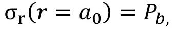
where 2a0 is the hole diameter. Rewritten in terms of Equation [1], Equation [2] yields the following equality:

Denoting Vp (r = a0) as Vp0, the initial conditions for cavity expansion are:
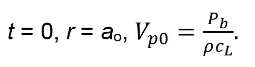
The Szendrei (1983) equation of motion of radial hole expansion in cylindrical symmetry is based on the conservation of momentum in the flow of displaced material. When suitably adapted to describe the radial motion of an expanding blasthole, it can be expressed in terms of explosive and rock parameters as follows:
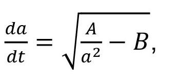
where a is the instantaneous blasthole radius at time t, and A and B are constant groupings of rock and explosive properties:
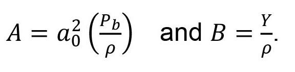
Y is the strength or resistance of the rock to radial motion. In general, the applicable strength parameter to use is the failure strength when the applied pressure exceeds the elastic limit. The appropriate failure strength for rocks is the unconfined compressive strength (UCS), as pointed out by Cunningham et al. (2007). UCS is also the strength parameter used in cavity expansion analysis when problems of stresses around pressurised cavities in geological materials are considered (Satapathy, 1997).
By separation of variables and integration of Equation [5] between the limits t = 0 and t = t, a relation is obtained between the time of expansion (t) and the corresponding expanded hole radius (a), as expressed by the following equation:

This equation can be inverted and solved for the blasthole radius (a) as a function of time (t):
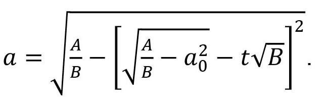
By multiplying out the square, Equation [8] can be rewritten as:
[1]
where the subscript r indicates that the longitudinal wave is radially directed, and cL is the longitudinal wave velocity (also called P-wave and seismic or sound velocity). Equation [1] holds at the wa-front, as well as at any point behind the wavefront within the stress pulse. The boundary condition for cavity expansion under the action of short-duration high-amplitude pressure forces expresses the equality of the radial (r) stress component in the rock at the surface of the blasthole to the borehole gas pressure (Blake, 1952; Goldsmith & Allen 1955):

On replacing A and B with their definitions as given in Equation [6], Equation [9] yields a simpler expression:
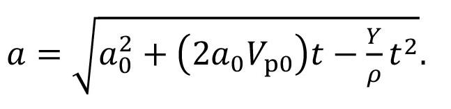
It is informative to write Equation [10] in dimensionless form:

[11]
Clearly, the second term under the square root drives blasthole expansion, whereas the third term resists expansion and eventually brings it to rest. The next section considers the questions of how long is the time of expansion and what final hole size is attained in that time.
Predictions derived from cavity expansion model
By manipulation of Equation [10], various features of blasthole expansion may be derived, as discussed below.
Expansion velocity
This velocity at any instant of time is obtained by differentiation of Equation [10] with respect to time, i.e.: [12]
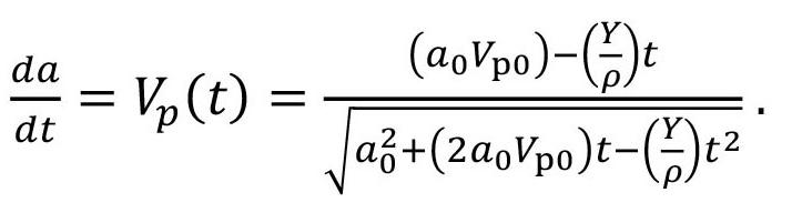
Equations [11] and [12] were evaluated for five types of rock with initial wall velocities defined by Equation [4], assuming an equivolume blasthole pressure of 4 GPa. This value is indicated by the expansion isentrope published by Cunningham et al. (2007) for a bulk emulsion explosive of density 1150 kg/m3. Rock properties required for evaluating the equations, together with the calculated values of initial wall velocity Vp0, are listed in Table I.
Granite refers to Swedish granite, possibly of the same type as used by Lundborg (1975) in his study of flyrock throw distances. The above rock properties are intended to be representative and not definitive, in order to illustrate the general features of hole expansion in various broad types of rock encountered in bench blasting.
While Equations [11] and [12] yield precise values and are, in principle, capable of defining the influence of various parameters on blasthole expansion and its velocity, it is far easier to ‘read’ the equations and gain insight into the general trends and rates of change by graphically representing the equations. Plots of radial expansion and expansion velocity for 100 mm blastholes are displayed in Figures 1 and 2, respectively. Expansion velocities for plotting are normalized to their initial (Vp0) values.
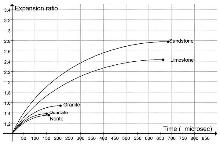
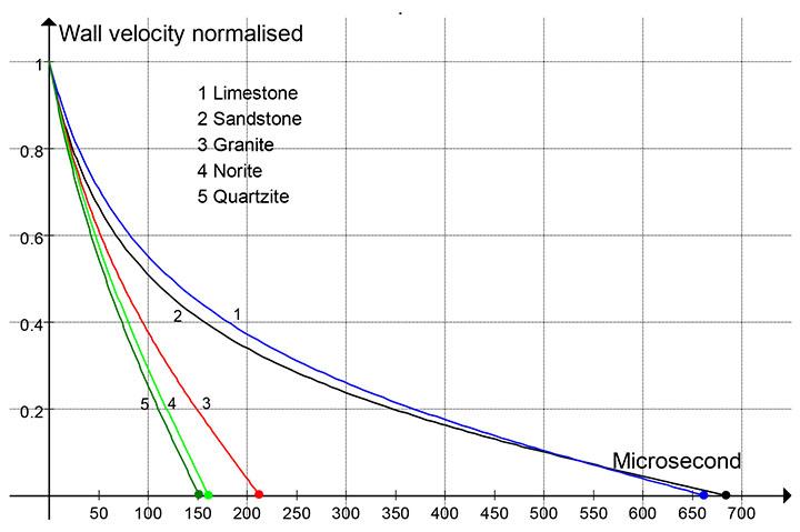
Figure 1 illustrates two primary features of hole expansion. At first, there is a short period of rapid hole growth, which is followed by a significantly longer period of slower growth. Hard rocks (quartzite, norite, and granite) attain 50% of their final hole dimeters in ~ 50 μs; the period of slow hole growth stretches to 150–210 μs. In contrast, soft rocks (limestone and sandstone) reach 50% hole growth at about 150 μs and terminate at ~ 650 μs. This contrasting behaviour between hard and soft rocks can be ascribed to the value of Y/ρ in Equation [11]: the larger the value of this parameter, the quicker is the approach to final hole size.
Rock
* Yumlu and Ozbay (1995)
** Stojadinovic et al. (2011)
Figure 2 displays a similar type of behaviour as Figure 1: a short period of rapid reduction of wall velocity and a relatively longer period of slow reduction. Reduction of 50% is attained at about 50 μs (hard rocks) and 125 μs (soft rocks), and 80% reduction within 350 μs (all rock types). Thus, the bulk of hole expansion occurs within fractions of a millisecond in both hard and soft rocks.
The solid symbols in Figure 1 and Figure 2 denote, respectively, the maximum expansion sizes and the associated expansion times, as calculated using the algebraic expressions derived below.
Blasthole expansion time
The blasthole diameter reaches its maximum value when the wall expansion velocity drops to zero. By inspection of Equation [12] for velocity, it is evident that the denominator is always a positive quantity: the instantaneous blasthole radius (as per Equation [10]). Hence, Equation [12] for the velocity will decline to zero only when the numerator does, i.e., at a time tF such that:


An important feature of Equation [13] is the direct proportionality of expansion time to blasthole radius. The inverse proportion between Y/ρ noted above in regard to expansion times is evident in Equation [13]. By replacing Vp0 with its definition in Equation [4], the influence of explosion pressure and rock properties on expansion time are revealed:
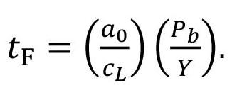
For a given explosive, tF is inversely proportional to rock strength and seismic velocity, and for a given rock, it is directly proportional to the blasthole pressure. Error analysis of Equations [4] and [14] for Vp0 and tF, respectively, shows that the dominant contribution to the fractional errors of these parameters derive from the uncertainty in borehole pressure (Pb).
Blasthole maximum expansion
Substitution of t = tF in Equation [10] for the blasthole radius and collecting terms yields the following expression:
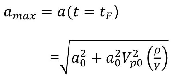
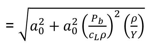


It may be seen that a dimensionless grouping of explosive and rock properties defines the final expanded size of the blasthole. It may further be seen that blasthole pressure is a strong driving force and rock seismic velocity is a strong moderating factor.
Based on a combination of Equations [13] and [15], a simpler definition of expansion time can be derived:

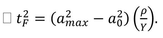
This formulation of expansion time is particularly useful when field observations of expanded hole diameters (sockets) are available. Rock properties of strength (Y) and density (ρ) are normally known in bench blasting operations.
Expanded blasthole volume
In cylindrical symmetry, the ratio of expanded hole volume (Ve) to its initial volume (V0) per unit length of blasthole is given by:
By Equation [18], this ratio can be rewritten as:

The dimensionless grouping of parameters on the righthand side is the scaling factor for blasthole volume growth. This grouping identifies the blasthole pressure as a strong driver of volume increase, while rock density and strength can be regarded as resisting volume growth, which is also strongly limited by high seismic velocities.
As described by Szendrei and Tose (2023), the expansion of a blasthole is accompanied by the generation, first, of a shock wave and, second, an elastic stress wave in the rock. These longitudinal waves of compression are driven into the rock for as long as the cavity wall is in motion, this period being tF as defined in Equation [14]. Owing to inelastic energy losses, the shock wave degenerates to an elastic wave close to the blasthole outside the ring of intense fracturing/crushing. Thereafter, the leading edge of the elastic stress wave would travel in time tF a distance equal to the length of the pulse (Lw), i.e.:
[23]
A physically more-insightful expression for Lw is obtained when tF is replaced by Equation [14]:

[24]
Thus, the pulse length is the product of hole radius and the ratio of blasthole equivolume pressure and rock strength. Over the short distances to various free faces, the influence of frequency dispersion on pulse length would be negligible; the attenuation of amplitude by various dissipative sources of frictional loss would similarly be negligible. Thus, for practical purposes, the pulse length of the stress wave would remain unchanged during its propagation through burden rock; nor would it be influenced by reflection from free faces.
Calculated characteristics of blasthole expansion
Expansion time (tF), relative radial expansion (amax/a0), relative volume (Ve/V0), and pulse length (Lw) were calculated using Equations [14], [18], [21], and [24], respectively. The calculations were carried out for 100 mm blastholes, using the rock and explosive properties listed in Table I. The results are presented in Table II.
Table II
Two general observations may be made from the data in Table II: (i) relative to rock and stemming movement as, for example, recorded by high-speed videos, blasthole expansion times are short—less than 1 ms, as compared to some tens of milliseconds for the initiation of rock movement; (ii) for the same explosive, volumetric expansion of blastholes can vary by a factor of 4 due to variations of rock density, sound speed, and strength.
Table II values are specific to 100 mm dimeter holes and can readily be scaled to other hole diameters through direct proportionality. When considering the influence of rock types, radial and volumetric expansion can be scaled in terms of a dimensionless grouping of rock and explosive parameters as identified in Equations [18] and [22].
Energetics of blasthole expansion
Residual pressure
Given the initial (V0) and final (Ve) values of blasthole volume per metre, the gas pressure (PF) at the end of blasthole expansion can, in principle, be calculated. This pressure is of considerable importance because it defines the quantity of energy consumed in the process of blasthole expansion, as well as the work capacity of the remaining (residual) pressure that acts on the surrounding rock mass. The polytropic equation of state is commonly applied to track changes in volume and pressure close to the explosion state and yields the following definition of the residual pressure:
[25]
[26]
where n is the polytropic index and Pb the initial (borehole) pressure. In the high-pressure regime of a detonative explosion, the index is generally taken to be 3. It is not a fundamental constant and the value of 3 is based on empirical observations (or deduced from thermochemical code calculations). The applicable value of n in the case of expanding blastholes will be considered in a later section when discussing its influence on both the residual pressure and the energy of blasthole expansion.
Based on Equations [21] and [22], Equation [26] can be reformulated as follows to display the influence of rock mechanical properties: [27]
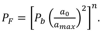
By Equation [18], the relative radius ratio can be defined as:

and by substitution in Equation [27]
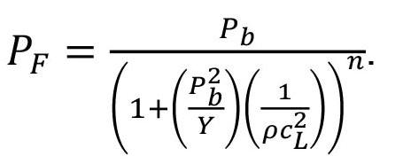
[28]
Equation [28] identifies some general characteristics of the residual pressure: (i) for a given rock type, PF is directly proportional to the initial borehole pressure; (ii) its value as a fraction of the initial pressure is determined by a grouping of rock parameters (ρ, Y, cL); (iii) extrapolation of PF to other rock types can be made in terms of the same grouping of parameters.
Work of blasthole expansion
Knowledge of expansion energy per unit volume of hole enlargement (EV) is important on two levels. The first and primary reason is that it may bring some clarity to the long-standing issue of energy partitioning in rock blasting. The second reason is that in non-mining but explosives-related technological fields, EV is recognized as a property of solid materials.
The core issue in the partitioning of blast energy is that about 50% of the energy released by a detonative explosion in the blasthole is unaccounted for when energy expenditures on throwing rock, radiation of seismic waves, and the fracturing of rock are measured in the field (Ouchterlony et al., 2004). This issue has long been clouded by competing views on the roles of detonation velocity, weight strength, chemical energy release, heave and shock energies, and, more recently, the role of Gurney energy, as measured in cylinder expansion tests (Essen et al., 2005; Nyberg et al., 2003). The general conclusion seems to be that a medley of possible causes –such as the diameter effect, non-ideal detonation, the crushed zone, and other (not specified) effects close to the hole may be responsible for the missing energy.
Regarding EV, a great deal of historical investigation has been devoted to the relationship between the volume of the cavity formed and the energy delivered in high-pressure impact and shock-loading events (Cunningham and Szendrei, 2004). A key finding was that each type of material – typically of engineering interest, such as metals, glasses and ceramics, concrete – displays a characteristic value of EV that is essentially constant in the hydrodynamic highpressure regime. Measurements of this value for rocks would be a useful contribution not only to the analysis of rock blasting, but to other engineering disciplines as well.
In this paper, we present a model for calculating EV in a way that answers many of the questions regarding shock and close-in effects and clearly identifies the portion of the explosion energy that is expended in the loosely termed ‘shock’ phase of blasting.
The expansion of explosion gases from state 1 (PB ,V0) to state 2 (PF, Ve) delivers work (energy) to the surrounding rock mass. Theoretically, this work (Wexp) could be calculated by evaluating the following line integral:

It can be shown that the polytropic Equation [25] yields the following solution:
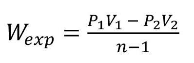
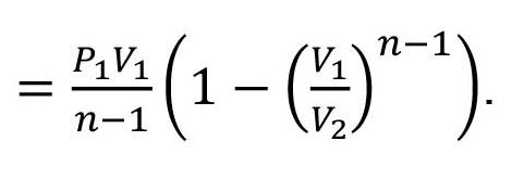
Equation [35] can be replaced with a combination of Equations [21] and [22]. Thus: [36]
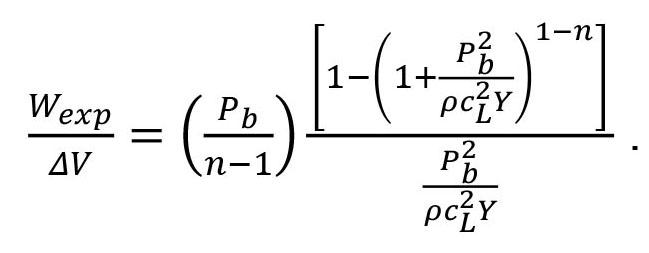
[29]
[30]
[31]
Equation [31] is the usual expression for the adiabatic expansion of a polytropic gas. It can be made specific to blasthole expansion when the pressure and volume parameters are interpreted in the same way as for the derivation of the expanded hole pressure, PF, i.e.:

The volume ratio (V0/Ve) in Equation [32] can be replaced by Equation [21]:
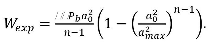
The volume of rock (per metre-hole) radially displaced is:
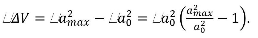
[32]
Values of residual pressure and energy consumption per unit volume of displaced rock were calculated by Equations [28] and [36], respectively, for the five types of rock described in Table I and are listed in Table III. Together with these model-calculated values, we list the corresponding values derived from African Explosives’ Vixen-i detonation code. A code-generated table listing pressure, specific internal energy, and specific expansion energy over a wide range of relative volumes may be found in Cunningham and Szendrei (2004). There, the detonation and expansion of an emulsion charge of density 1150 kg/ms was analyzed. To allow direct comparisons with Equation [36], specific energy values, as delivered by the code, were converted from MJ/kg to MJ per 9 kg, which is the charge mass per metre of bulk emulsion in coupled 100 mm blastholes.
The correspondence between model predictions and code calculations in Table III varies from poor to very good, the difference between the two methods of calculation being far more pronounced in the case of the final pressure PF. It may also be noted from Table III that the differences in both PF and EV values from code calculations decrease with decreasing values of the volume ratio. For an explanation of these trends, it is necessary to examine polytropic expansion in more detail.
[33]
[34]
Hence, the energy spent to displace unit volume of rock is the quotient of [33] divided by [34], which, after some simplifications, yields the expression:
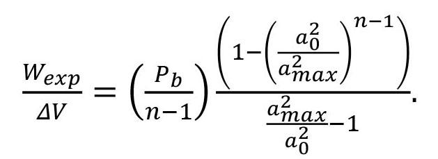
Equation [26] shows that the predicted value of PF varies with the polytropic index (n = 3) as the third power of the expansion ratio, and would thus be sensitive to small changes of this index. The predicted values of PF listed in Table III presuppose that the polytropic index n is a constant equal to 3.0. The change in PF caused by a change (Δn) in the value of n can be established by considering the following ratio, which is based on Equation [26]:

[35]
As it stands, Equation [35] is not readily applicable to the prediction of the energy of blasthole expansion because, unlike Pb and a0, amax is not known a priori. The ratio of blasthole radii in
[37]
Cavity expansion – residual pressure and energy consumption
Here, the predicted value of PF calculated with a reduced value of the polytropic index is normalized to its value when n = 3. Equation [37] is plotted in Figure 3, with Δn being a parameter lying between 0.1 and 0.5.
It is evident that the ‘residual pressure’ in the blasthole increases when the polytropic index drops below n = 3. More importantly, the enhancement of PF is about 50% or less when the volume expansion ratios are less than 3. When the expansion ratio exceeds 4, PF may

double or even triple as the expansion ratio increases towards 10. Such large deviations from the predicted (n = 3) values of PF are evident in Table III and are to be expected when the effective value of the polytropic index is less than 3 at large expansion ratios. In fact, if n values of 2.30 and 2.44 are chosen for sandstone and limestone, respectively, the correspondence between the PF values predicted by the polytropic model and the expansion isentrope would be exact.
The relatively small deviations (< 10%) between code and polytropic model predictions of expansion energy, E/V, at all values of the relative volume are due to the way gas expansion energy is delivered with increasing volume in the blasthole. The details of this process are very well described by Esen et al. (2005), who reported measurements of the conversion of explosion gas internal energy to external work using the cylinder expansion technique. By measuring the radial velocity of the cylinder wall, they were able to establish its kinetic energy as a function of its radial expansion and, hence, of the expansion ratio. Their measurements included 11 types of commercial explosives, ranging from pure emulsion to pure ammonium nitrate. In all cases, about two-thirds of the final kinetic energy was delivered at an early stage of expansion, at relative volume ratios of < 2; this fraction increased to 80% in high velocityof-detonation (VOD) compositions where afterburning had little effect on the conversion of expansion energy to external work. Over such a limited range of expansion, the polytropic model with n = 3 yields quite accurate estimates of expansion energy.
All suppliers use their own version of an ideal detonation code to calculate energies. A review of the technical information supplied by manufacturers shows a wide range of methods of reporting both VOD and energy (Torrance and Scott, 2015). These authors suggested that stronger brittle rock masses will release the explosion gases at higher pressures than weaker softer rock masses. If the
100 MPa cut-off pressure is based on blasting in hard rock (say, igneous or metamorphic rocks), then it would be reasonable to use a 50 MPa cut-off for medium strength rock (such as fresh sandstone) and, say, 20 MPa cut-off for soft rock (such as weathered sandstones or siltstones often found in coal overburden). These general expectations are borne out in Table III.
Table III indicates that residual pressure, here understood as the pressure in expanded blastholes, in rocks of various strengths is of the order of 100 MPa, the range being from 35 MPa to 635 MPa. To give some context to these values, large calibre (150 mm, say) artillery guns firing projectiles of some 10s of kilograms typically operate at 200 MPa to 350 MPa maximum breech pressures. It is to be remembered that even at the lowest predicted value of expanded hole pressure (36 MPa for sandstone), explosion gases have enlarged the blasthole but, at this stage, have not yet delivered any external work to move the rock mass. The upper end of the predicted range (norite at 638 MPa) suggests that violent throw of burden rock may be expected in hard rocks as the high residual pressure forces act on the rock mass.
Regarding expansion work per unit volume (EV), predicted values in Table III are remarkably similar to values reported in engineering literature for the strengths of various protective construction layers. Energy values in related technological fields are commonly cited in units of kJ/cm3, which is dimensionally and numerically equivalent to GJ/m3, as listed in Table IV. For example, the following cavity expansion energies (in kJ/cm3) have been reported: 0.28–0.35 for concrete and hard aluminium, 0.405 for glass-fibre reinforced plastics, and 1–2.5 for mild to ultra-hard steels. Based on semi-quantitative arguments, Cunningham and Szendrei (2004) suggested that hole expansion would consume about 1 kJ/cm3, a value that Ouchterlony et al. (2004) deemed to be of the right order in comparison with the unexplained losses in blast energy partitioning.
Energy efficiency of blasthole expansion
The efficiency ( ε) of energy transfer from explosion energy to rock in the process of blasthole expansion may be defined as the ratio of the energy consumed to enlarge the blasthole to the energy liberated by the detonation of the charge load. This ratio can be formulated as follows: [38]

where EV is expansion work per unit volume of displaced rock, J/m3; ΔV is displaced rock volume, m3; C is quantity of charge, kg; ΔHd is specific explosion energy, MJ/kg. Both EV and ΔV are evaluated per metre of blasthole.
* Rock volume and work of expansion are per metre of blasthole.
Equation [38] was evaluated for the five rock types listed in Table I using the following parameter values: EV values as listed in Table III; ΔV is defined by Equation [34]; C is 9 kg/m-hole; specific explosion energy is 4 MJ/kg (bulk emulsion at density 1150 kg/m3). Predicted values of energy transfer efficiencies are listed in Table IV.
Table IV indicates that roughly 30% to 40% of explosion (chemical) energy is converted to expansion work in the blasthole. An important point to remember is that only a certain fraction of the explosion energy can be converted to mechanical work. This fraction – the Gurney energy – is measured by cylinder expansion testing (e.g., Essen et al., 2005), and is now accepted as a better definition of the work capacity of an explosive than underwater testing and various measures of weight strength. Nyberg et al. (2003) and Ouchterlony et al. (2004) reported relative Gurney energies for a wide range of commercial explosives as being between 40% and 70%, the value for bulk emulsion being 60% to 70%. Adopting 65% as a representative value for bulk emulsion at a density of 1150 kg/m3, the efficiency values in Table IV range from 65.8% to 48.7%, or roughly 55%, when recalculated relative to the available Gurney energy.
On the basis of the above considerations, two conclusions are immediately evident: (i) blasthole expansion is the primary consumer of the available (mechanical) explosion energy; and (ii) it is at least equal to, if not more than, the energy expended in all other external effects of a blast, such as kinetic energy of displaced and thrown rock, radiation of seismic waves, fracture and comminution of rock, and air blast.
These conclusions provide a ready interpretation of some very relevant observations made by Ouchterlony et al. (2004). These workers reported that up to one-half of the available (Gurney) energy is ‘lost’, i.e., not accounted for in field measurements of blast energy partitioning. They also noted that there is some evidence suggesting that ‘crushing’ around the blasthole is the dominant energy loss. In the absence of clear ideas on the role of blasthole expansion, phrases such as interaction between detonation pressure/shock wave/blast wave and the blasthole skin, followed by compaction, crushing, plastic flow, and other in-hole and near-zone effects have been commonly used in the literature to indicate that there is some ill-understood and energy-intensive process occurring in the vicinity of the blasthole. Many, if not all, of these allusions can be placed on a firm footing by linking them to the process of blasthole expansion. Model calculations of blasthole energetics, as summarised in Tables III and IV, indicate that a large portion of the missing energy can be attributed to gas expansion work delivered in the blasthole.
At the completion of radial expansion, a reservoir of highpressure gas exists in the enlarged blasthole that contains a significant portion of the Gurney energy liberated in each hole as the internal energy of detonation gases. This fraction is 35% to 55% (for the rock types modelled) and is the source of further work on the surrounding rock mass, resulting in its displacement and throw.
Seen in this context, flyrock is a hazardous byproduct of a much more general process of rock movement. It has been pointed out (Szendrei and Tose, 2023) that it is neither high pressure nor excessive energy in a broad sense that is directly responsible for the generation of excessive flyrock: rather, it is the excessive momentum that some rock fragments acquire in the course of the general movement of burden, bench top, and stemming under the influence of gas pressure forces.
Clearly, cavity expansion is unable to analyze these late-time processes, but it does define the initial conditions – gas volume,
density, pressure and internal energy – in the expanded blasthole, knowledge of which would be a necessary starting point for the analysis of momentum transfer to rock.
The key contribution of the concept of blasthole expansion to blast engineering is a much-improved ability to understand how energy is dissipated, leading to improved blast designs. The past decade has seen increasing awareness that the energy sinks of blasting are poorly understood, with general acknowledgement that not more than 50% of explosives’ energy could be accounted for from the blasting results; namely, fragmentation, movement, and stress waves.
Cavity expansion is easy to overlook because inelastic expansion of the blasthole is very seldom seen: blasting, by its nature, removes the blasthole. However, this process is highly absorbent of energy, a fact strongly supported by high-velocity impact expansion analysis (where kinetic energy alone creates consistent non-elastic volume per unit of energy) and by broad evidence that blastholes detonated in the solid for “springing” purposes generally double in diameter (Cunningham and Szendrei, 2004), which ties in with the presented cavity expansion theory in hard rocks.
The cavity expansion model presented in this paper leads to the conclusion that detonation in a blasthole causes immediate, shockdriven, non-elastic deformation of the rock, resulting in permanent chambering of the hole. As an illustration of such chambering, Figure 4 is taken from a demolition site in which a blasthole failed to break the reinforced concrete slab: comparison with an uncharged hole shows clearly that the hole expanded from 32 mm to about 50 mm. The blasthole had been charged with Magnum 365 coupled cartridges.
In conventional blasting, the rock burden normally breaks out, so there is a general lack of awareness of this chambering phenomenon among blasting engineers. The full chamber is only detectable where holes are shot in the solid or in any sockets remaining from overburdened holes. The assumption is then often made that the enlarged hole resulted from rock particles ejected from the crushed perimeter zone, but this is not so. Explosive pressures are normally greatly in excess of rock strength, and permanently deform the confining medium by radial displacement of the rock matrix. Further evidence can be seen in the same blast at another hole where the crush zone is also evident (Figure 5).
Similar results were observed by Dr Ewan Sellers of AECI Mining Explosives, who has been involved with collaborative industry research on the development of models to simulate blasting in a variety of rock types and conditions, such as the Hybrid Stress Blast Model, HSBM. The results from some of the work on large standard concrete blocks are shown in Figure 6.
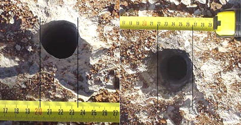


Irrespective of any interpretation in terms of momentum and energy transfer to the rock matrix, the photographs in Figures 4 to 6 illustrate the most basic feature of springing the blasthole. Whether conducted to enlarge the bottom of a blasthole with a small charge or to create a large chamber with a succession of small charges, springing would not be a viable technique were it not for the formation and stability of an enlarged blasthole. The ability to blast a number of charges in the same chamber further underscores the stability of its walls.
A well-established analytical model for calculating the displacement of solid materials in high-velocity high-pressure impact events has been adapted to describe the radial expansion of blastholes following the detonation of the explosive charge load. In essence, the model defines the dynamics of shock-driven blasthole expansion, which, in turn, gives rise to two key physical effects that ultimately determine the fracturing and movement of burden rock. The first legacy effect is the radiation of an elastic stress wave into the burden when the strength of the initial shock wave has been sufficiently diminished in the vicinity of the blasthole by inelastic rock response. The second legacy effect is the pressure of explosion product gases that remain in the expanded blasthole after the shock- and stress-wave phases. In our interpretation, the stress wave and its various reflections are primarily responsible for fracturing the burden; gas pressure is responsible for the inertial movement of the fractured rock. While it is generally acknowledged in the literature that the fundamental sources of energy in rock blasting reside in the shock phase and the internal energy of explosion gases (e.g., Langefors and Kihlstrom, 1970; Brinkmann, 1990; Olsson et al., 2001), the physical mechanisms by which these sources interact with the rock have not received detailed and quantitative interpretation.
In this study, we present a physical model and quantitative predictions to demonstrate how the shock phase contributes to the delivery of energy to the rock. The key prediction of the model is the radial expansion ratio (amax/a0) or its square, the volume ratio (Ve/V0). A wide range of features of blasthole expansion and rock response are based on this ratio; namely:
tF expansion time
PF expanded hole gas pressure
ΔV volume of rock displaced radially
EV energy consumed in displacing unit volume of rock
ε energy efficiency of blasthole expansion
Lw stress wave pulse length
The model yields a definition of amax in terms of explosive and rock properties; namely, a0, Pb, Y, ρ, cL, so that for a given blasthole and explosive, all characteristics of hole expansion can be calculated from first principles.
In broad detail, blasthole expansion is completed in under 1 ms and may be as short as 150 μs in hard rocks. In this time, the blasthole undergoes radial expansion of between 50% to 300%, resulting in blasthole volumes increasing by factors of 2 to 9. The gas pressure in the expanded blasthole is of the order of 100 MPa, but with a wide range between about 35 MPa and 650 MPa, again depending on rock mechanical properties. Blasthole expansion consumes the largest fraction of the available mechanical (Gurney) energy of detonation product gases. At its completion, about 45% of Gurney energy still remains in the expanded blasthole and is the source of further work on the external rock mass, specifically the movement of the burden and the generation of flyrock.
Hole expansion is so rapid that it is completed even before the burden is fully fractured. Hence, the explosion gases are constrained to remain in the expanded hole (whether they permeate fractured rock or not at a later stage). The terms ‘residual pressure’ and ‘remnant energy’ are misnomers. These expressions give the impression that, at the pressures remaining after hole expansion, the gas lacks the ability to do further work, when, in fact, their work of pushing rock is just beginning. This is supported by visual observations and field measurements using high-resolution data capture of items including velocity of detonation and pressure measurements. These processes in the blasthole are completed prior to any visual indications by high frame-rate camera recordings of rock movement or energy release by gas venting.
Blake, F.G. 1952. Spherical propagation in solid media. The Journal of the Acoustical Society of America, vol. 24, no.2, pp. 211–215. Brinkmann, J.R. 1990. An experimental study of the effects of shock and gas penetration in blasting. Proceedings of 3rd International Symposium on Rock Fragmentation by Blasting. FRAGBLAST90, Brisbane, Queensland, 26–31 August 1990, A.A. Balkema, Rotterdam, pp.55–66.
Cunningham, C. 2006. Concepts of blast hole pressure applied to blast design. Fragblast, vol.10, no.1–2, pp. 33–45.
Cunningham, C.V.B., Sellers, E., Szendrei, T. 2007. Cavity expansion energy applied to rock blasting. Moser P et al. (eds.) Proceedings EFEE Conference of Explosives Engineers, European Federation of Explosives Engineers, Vienna, pp. 27–38.
Cunningham, C.V.B., Szendrei, T. 2004. Cavity expansion by hypervelocity impact applied to blasthole expansion by
detonation. Proceedings of 30th Annual Conference on Explosives and Blasting Technique: Vol. 1. International Society of Explosives Engineers, Cleveland, OH, USA.
Essen, S., Nyberg, U., Hiroyuki, A., Ouchterlony, F. 2005. Determination of the energetic characteristics of commercial explosives using the cylinder expansion test. Swebrec Report No. 2005:1. Swedish Blasting Research Centre, Lulea University of Technology, Sweden.
Goldsmith, W., Allen, W.A. 1955. Graphical representation of the spherical propagation of explosive pulses in elastic media. The Journal of the Acoustical Society of America, vol. 27, no.1, pp. 47–55.
Held, M. 1995. Verification of the equation for radial growth by shaped charge jet penetration. International Journal of Impact Mechanics, vol.17, pp. 387–398.
Held, M., Kozhushko, A.A. 1998. Radial crater growing process in different materials with shaped charge jets. Propellants, Explosives, Pyrotechnics, vol. 24, no. 6, pp. 339–342.
Hustrilid, W. 1999. Blasting Principles for Open–Pit Mining. Vol. 2 – Theoretical Foundations. Balkema, Rotterdam.
Kolsky, H. 1953. Stress Waves in Solids. Clarendon Press, Oxford.
Langefors, U., Kihlstrom, B. 1963. The Modern Technique of Rock Blasting, Almqvist and Wiksell, Stockholm.
Ljunggren, C., Stephansson, O., Alm, O., Hakami, H., Mattila, U. 1985. Mechanical properties of granitic rocks from Gidea, Sweden. SKB Technical Report No. 85-06. Swedish Nuclear Fuel and Waste Management Co., Stockholm.
Lundborg, N., Persson, A., Ladegaard–Pedersen, A., Holmberg, R. 1975. Keeping the lid on flyrock in open–pit blasting. Engineering and Mining Journal, no. 5, pp. 95–100.
Melosh, H.J. 1988. Impact Cratering: A Geologic Process. Oxford University Press, New York, pp. 29–45.
Naz, P. 1989. Penetration and perforation of a steel target by copper rods. Measurement of crater diameter. 11th Symposium on Ballistics Brussels, Belgium. pp. 333–341.
Nyberg, V., Arvanitidis, I., Olsson, M., Ouchterlony, F. 2003. Large size cylinder expansion tests on ANFO and gassed bulk emulsion explosives. Explosives and Blasting Techniques. Proceedings of the 2nd World Conference on Explosives and Blasting Technique Holmberg, H. (Ed.). 10–13 September 2003, Prague, Czech Republic, A.A. Balkema Publishers, Lisse, pp.181–191.
Olsson, M., Nie, S., Bergkvist, I., Ouchterlony, F. 2001. What causes cracks in rock blasting? EXPLO2001, 28–31 October 2001, Hunter Valley, NSW, Australian Institute of Mining and Metallurgy, no. 4/01.
Ouchterlony, F., Nyberg, U., Bergkvist, I., Lars, G., Grind, H. 2003. The energy balance of production blasts at Nordkalk’s Klinthagen quarry. Explosives and Blasting Techniques. Proceedings of the 2nd World Conference on Explosives and Blasting Technique, Holmberg, H. (ed.) (10–13 Sept. 2003), Prague, Czech Republic. A.A. Balkema Publishers, Lisse, pp. 193–203
Ouchterlony, F., Nyberg, U., Bergkvist, I., Lars, G., Grind, H. 2004. Where does the explosive energy of rock blasting rounds go? Science and Technology of Energetic Materials, vol. 65, no. 2, pp. 54–63.
Satapathy, S. 1997. Application of cavity expansion analysis to penetration problems Report No. IAT.R 0136. Institute for Advanced Technology, University of Texas, Austin, USA.
Stojadinovic, S., Pantovic, R., Zikic, M. 2011. Prediction of flyrock trajectories for forensic applications using ballistic flight equations. International Journal of Rock Mechanics and Mining Sciences, vol. 48, pp. 1086–1094.
Szendrei, T. 1983. Analytical model of crater formation by jet impact and its application to calculation of penetration curves and hole profiles. Proceedings of the 7th International Symposium on Ballistics, The Hague, The Netherlands, pp. 575–583.
Szendrei, T. 1995. Analytical model for high-velocity impact cratering with material strengths: extensions and validation. Proceedings of the 15th International Symposium on Ballistics, Jerusalem, pp. 123–131.
Szendrei, T. 1998. Link between axial penetration and radial crater expansion in hypervelocity impact. Proceedings of the 17th International Symposium on Ballistics. Midrand, South Africa, pp. 325–332.
Szendrei, T., Tose, S. 2022. Flyrock in surface mining–Limitations of current predictive models and a better alternative through modelling the aerodynamics of flyrock trajectory. Journal of the Southern African Institute of Mining and Metallurgy, vol. 122, no. 12, pp. 725–732. http://dx.doi.org/10.17159/2411–9717/1873/2022
Szendrei, T., Tose, S. 2023. Flyrock in surface mining–Part 2. Causes, sources and mechanisms of rock projection. Journal of the Southern African Institute of Mining and Metallurgy, vol. 123, no. 12, pp. 557–564. http://dx.doi.org/10.17159/2411–9717/2583/2023
Torrance, A.C., Scott, A. 2015. What is relative about energy? 11th International Symposium on Rock Fragmentation by Blasting Spathis A.T., Gribble D.P., Torrance A.C., Little T.N. (ed). Sydney, NSW, AusIMM, 24–26 August 2015, pp. 447–454.
Yumlu, M., Ozbay, M.U. 1995. A study of the behaviour of brittle rocks under plane strain and triaxial loading conditions. International Journal of Rock Mechanics Mining Science & Geomechanics Abstracts, vol. 32, no. 7, pp. 725–737. u
Affiliation:
University of Toronto, Canada
Correspondence to:
J. Hadjigeorgiou
Email:
john.hadjigeorgiou@utoronto.ca
Dates:
Received: 16 Feb. 2024
Revised: 2 Jun. 2024
Accepted: 8 Aug. 2024
Published: September 2024
How to cite:
Hadjigeorgiou, J., Thorpe, S.J., Storimans, E., and Agrensa, F.D. 2024. Impact of steel properties on the susceptibility to corrosion of weld mesh and mesh straps. Journal of the Southern African Institute of Mining and Metallurgy, vol. 124, no. 9. pp. 517–526
DOI ID: http://dx.doi.org/10.17159/24119717/3295/2024
ORCID: J. Hadjigeorgiou http://orcid.org/0000-0002-6047-3964
by J. Hadjigeorgiou, S.J. Thorpe, E. Storimans, and F.D. Agrensa
Abstract
Reinforcement and surface support are part of an integrated system that transfers and shares load until the excavation surface is stabilized or until the ground support system fails. Steel mesh is the most popular primary surface support element in underground hard rock mines in Canada. Mesh straps are a secondary surface support that provide additional containment as they distribute the load between and across the reinforcement elements.
This investigation addresses the role of steel properties, and in particular steel chemistry, in the long-term performance of mesh and mesh straps when exposed to an aggressive corrosive environment. It reports on comparative accelerated corrosion studies to compare the resistance to corrosion of different surface support elements. This has significant implications on the choice of surface support and the anticipated rehabilitation requirements.
Keywords
accelerated corrosion of ground support, primary and secondary surface support, steel properties
Introduction
A ground support system employs both reinforcement and surface support elements to maintain the integrity of an excavation in hard rock for its intended working life. Although there are multiple reinforcement elements in use, including conventional and energy-absorbing rockbolts, the main surface support options are shotcrete and mesh.
Steel mesh is the most popular surface support element in underground hard rock mines in Canada to hold and retain the fractured rock between the reinforcement elements under both static and dynamic loading conditions. Mesh straps are often used as a secondary support over mesh or shotcrete, to contain the rock mass and distribute the load between the reinforcement elements.
In practice, mesh is often the weakest link in a ground support system (Simser, 2008). Hadjigeorgiou and Stacey (2018) noted that mesh can fail as a result of multiple factors that include installation related issues (e.g., mesh opening due to inadequate overlap, or rockbolt plates cutting through the screen), damage (e.g., due to flyrock following blasting, or equipment that caused damage), and the inability of the mesh to meet the static and seismic loads. All these factors affect the long-term performance of mesh and straps that can be further degraded when exposed to an aggressive corrosive environment (Figure 1).
Beyond standard quality assurance and quality control (QA/QC) processes, the traditional focus of investigations of the performance of mesh is on the capacity and deformation of different screen types, e.g., different gauges of weld mesh, (Tannant, 1995). Of additional interest are comparisons between high-tensile strength chain-link and weld mesh, (Player et al., 2008). These laboratory tests provided valuable insight into the anticipated field performance. The limitations of these laboratory studies in extrapolating it to field performance must be fully understood. Baek et al. (2020) used numerical experiments to demonstrate the significant impact of test configuration on the results.
There is limited data on the susceptibility of mesh to corrosion and even less on mesh straps. Hassell et al. (2010) extrapolated the relationship between the reduction in mesh strand diameter due to corrosion and peak load capacity of 1.3 m × 1.3 m mesh sheet. Dorion and Hadjigeorgiou (2014) collected 60 strand samples of #6 (4.9 mm diameter) mesh from Canadian mines exposed to corrosive environments (Figure 3). These were tested to determine the residual tensile strength (or loss in strength) of the wire since installation. Wu et al. (2018) undertook a comparative laboratory study to demonstrate that mesh sheets under ‘dry’ conditions displayed minimal corrosion effects over 12 weeks, while wet–dry cycle mesh specimens exhibited significant corrosion. Hadjigeorgiou (2016) qualified the influence of corrosion on the capacity of ground support elements to meet the long-term design requirements.
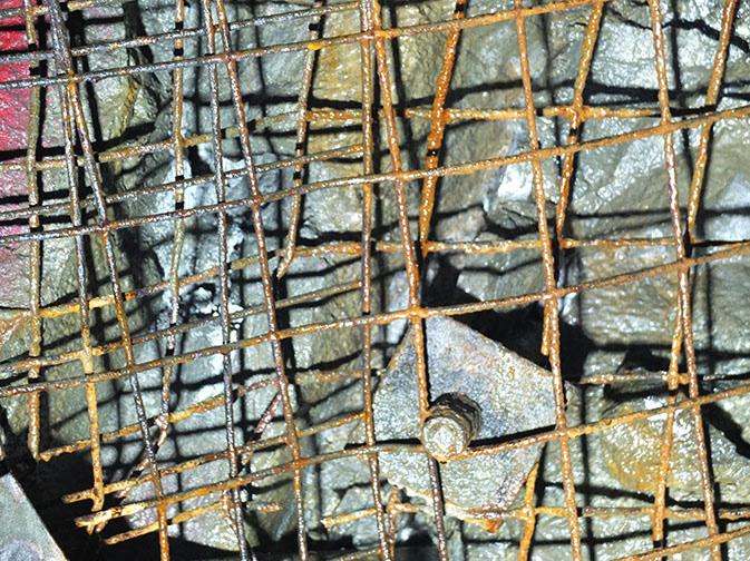

This paper focuses on the susceptibility of mesh and straps to corrosion with the emphasis on the role of steel properties. This investigation was part of a rigorous QA/QC of an underground mine in Canada where part of its qualification process involved an investigation of two sets of mesh and mesh straps for their susceptibility to corrosion.
Mesh and mesh strap susceptibility to corrosion
It is standard practice that the introduction of a ground support product in underground mines is preceded by a rigorous qualification process. In the case of new ground support elements, this may require a comprehensive qualification process prior to a field trial. In the case of conventional systems, the focus is on compliance with predefined thresholds that are typically focused on meeting capacity and deformation guidelines under laboratory and field conditions. The susceptibility to corrosion is often not part of the process. It has been demonstrated that this can be critical in certain cases when the ground support elements are anticipated to be exposed to potentially corrosive environments.
Long term studies using coupons in an underground mining environment can provide valuable insights on the susceptibility to corrosion of different steel products over time (Figure 2). These tests are, however, both expensive and time consuming to conduct. Accelerated corrosion techniques can provide the relative performance of different ground support elements in a short time. This is important when a decision is to be made on which product to prioritize for field trials. Examples of variations in their susceptibility to corrosion of ‘similar’ expandable bolts have been provided by Hadjigeorgiou et al. (2020) and for it should read friction rock stabilizers by Hadjigeorgiou et al. (2023)
This paper reports on comparing the influence of steel properties on the susceptibility to corrosion of two sets of mesh and mesh straps from different suppliers. It was part of a due diligence protocol by a mine site aiming to optimize its ground support practice and anticipate the long performance of its primary and secondary support.
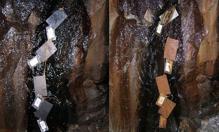
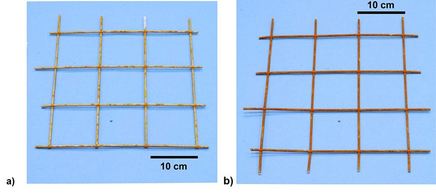

The mine provided a series of #6 mesh samples typically used as part of its ground support standard to compare their susceptibility to corrosion. For the purposes of this paper, the two #6 mesh products are referred to as M1 and M2 (Figure 3). All samples were received in good condition. None were treated with any corrosion resistant coating, such as galvanization. Of interest was their comparative resistance to corrosion when exposed to the same aggressive environment to anticipate whether their long-term performance would be equivalent.
Mesh straps are bands of heavy #0-gauge welded mesh, typically available in precut lengths of 1.2 m - 4 m (4-13 ft). They are easy to install because bolts can be fitted at convenient locations through the mesh, (Hadjigeorgiou and Potvin (2012). For the purposes of this investigation, the #0-gauge mesh straps are identified as sample S1 and S2, (Figure 4).
A chemical analysis based on ASTM E1019-11, 2011 was used for the carbon and sulfur analysis, and inductively coupled plasma atomic emission spectroscopy following the ASTM E1479-16, 2016 procedure was used to determine the concentration of the
remaining elements. The average of three specimens was used for all analyses. Table I summarizes the results of the chemical composition analysis for the #6 M1 and M2 mesh and the S1 and S2 mesh straps.
In general, similar mechanical properties for mesh can be achieved by using different concentrations of chemical alloying elements. Table II describes advantages and limitations of specific elements in the chemical composition of low carbon steel.
For the purposes of this investigation, the hardness of the steel was determined using the Rockwell B hardness test. The test is a measure of the resistance of the material to permanent indentation
and can be used to estimate the tensile strength of the steel. The Rockwell B hardness was determined using a tungsten carbide ball as the indenter with a diameter of 1.588 mm (ASTM E18-22, 2022). Conversion from Rockwell B hardness to approximate tensile strength was made according to ISO 18265:2013. For comparison purposes, the minimum tensile strength, based on the ASTM A1064/1064M-22, 2022 standard is also provided. The results for the mesh are summarized in Table III and for the mesh strap in Table IV.
It is important to note the difference in mechanical properties, between the two mesh, and the mesh strap products. This should be part of the QA/QC process during the manufacturing process and can be compared with additional tensile tests.
Comparative chemical composition between M1 and M2 mesh and S1 and S2 mesh straps
Table II
Advantages and limitations of specific elements in the chemical composition of low carbon steel Element
Advantages
Carbon (C)
Sulfur (S)
Manganese (Mn)
Phosphorus (P)
Silicon (Si)
Limitations
Defines the strength and hardness of rockbolts. Can result in lower ductility, toughness, and machinability.
Increases machinability. Decreases weldability, impacts toughness and ductility.
Improves wear resistance and increases strength without reducing forgeability.
Results in higher strength and hardness and better machinability.
Increases tensile and yield strength, hardness, and forgeability.
Nickel (Ni) Increases strength and hardness without sacrificing ductility and toughness.
Chromium (Cr)
Copper (Cu)
Contributes to increased strength, hardness, toughness, resistance to wear and abrasion, and reduces susceptibility to corrosion.
Beneficial to the corrosion resistance of steel.
Results in higher brittleness.
If combined with carbon, then Cr is not available for corrosion resistance.
Table III
Rockwell B hardness and approximate tensile strength for mesh samples M1 and M2
Table IV
Rockwell B hardness and approximate tensile strength for the mesh strap
tensile strength (ISO 18265:2013)
tensile strength (ASTM A1064/A1064M-22, 2022)
Experimental set-up for accelerated corrosion investigations
Accelerated corrosion studies have been used in the past to investigate the susceptibility to corrosion of the steel used in different ground support elements, e.g., expandable rockbolts Hadjigeorgiou et al. (2020), or friction rock stabilizers Hadjigeorgiou et al. (2023). For the purposes of the present investigation, a battery of accelerated corrosion tests was performed to provide a direct comparison between the steel used in the two mesh types and two mesh straps. The objective was to establish if there was a material variation in performance when exposed to an aggressive corrosion environment.
The experimental set-up for open-circuit potential (OCP), linear polarization resistance (LPR), electrochemical impedance spectroscopy (EIS), and potentiodynamic anodic polarization (AP) is provided in Figure 5. A three-electrode cell was used for all experiments. The counter electrode consisted of a platinum mesh and the reference electrode was an Ag/AgCl electrode filled with 3 M KCl. The working electrode was composed of either a mesh or a mesh strap sample. Measured potentials were converted to the saturated calomel electrode scale for reporting. The electrolyte composition is provided in Table V, with the pH adjusted to 2.7 using sulfuric acid.
Open-circuit potential (open cell potential)
The OCP is the potential at which a specimen will equilibrate in a given solution when there is no externally introduced bias applied to the cell. OCP measurements are potentiometric experiments and involve measuring the potential of the material of interest versus a reference electrode with time.
The OCP investigations were conducted in accordance with ASTM G5, and the results are summarized in Figure 6. The OCP for M1 was -0.610 V vs SCE, while the OCP for M2 was -0.621, suggesting that M2 is more susceptible to corrosion than M1 because of its more active open-circuit potential.
An interpretation of the relative performance of the mesh is possible by reference to their chemical composition in Table I. Increased C, P, and Si, content in M2 should decrease the corrosion

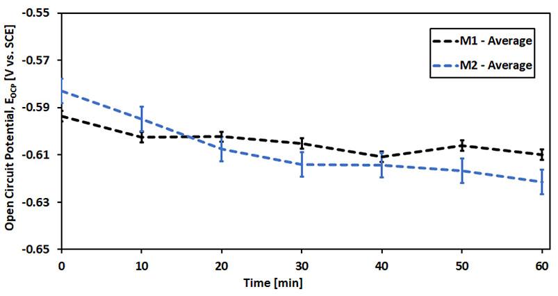
Table V
Lixiviate composition (electrolyte) used in accelerated corrosion investigations
resistance relative to M1. In addition, the slight increases of Cu and Ni content of M1 will improve its corrosion resistance relative to M2.
Linear polarization resistance
LPR is an electrochemical technique used to estimate the corrosion rate near or at the open circuit potential. In this technique, the material is typically biased both anodically and cathodically on the order of ± 10–30 mV relative to the open circuit potential. With the application of said small potential bias in many material–electrolyte systems, this technique can be considered largely non-destructive in nature. The resistance to corrosion can be estimated by taking the slope of the applied potential versus current curve (ASTM G3).
LPR measurements were performed in accordance with ASTM G59-97 (2014). The results are illustrated in Figure 7 and Table VI. It can clearly be seen that M1 has a higher polarization resistance, (Rp), than M2 and is less susceptible to corrosion. This is reflected in the estimated corrosion rates in Table VI which are in agreement with the OCP results that suggest M2 has a higher corrosion rate than M1.
Electrochemical impedance spectroscopy
EIS requires the application of a small (± 5–10 mV) alternating voltage (AC) signal imposed on either the OCP or a given DC bias of a material and measuring the resultant phase shift and amplitude of the current. The frequency response is analyzed to produce an electrical circuit analogue to identify parameters such as solution resistance, interface inductance and capacitance, and charge transfer resistance in relation to the interfacial structure.
The equivalent circuit analogous to the interfacial structure for this investigation is illustrated in Figure 8, and the results of the EIS Nyquist plot for each material are shown in Figure 9. All tests followed ASTM G106-89 (2015). In reference to Figure 9:
Rs Solution resistance
Rct Charge transfer resistance of the electron across the metal/ electrolyte interface
Rf Film resistance of the oxide film
Rad Resistance as a result of adsorbed corrosion intermediates
Qf Film capacitance
Qdl Double layer capacitance
Lad Inductance of adsorbed layer

Results of LPO analysis and estimated corrosion rate for mesh
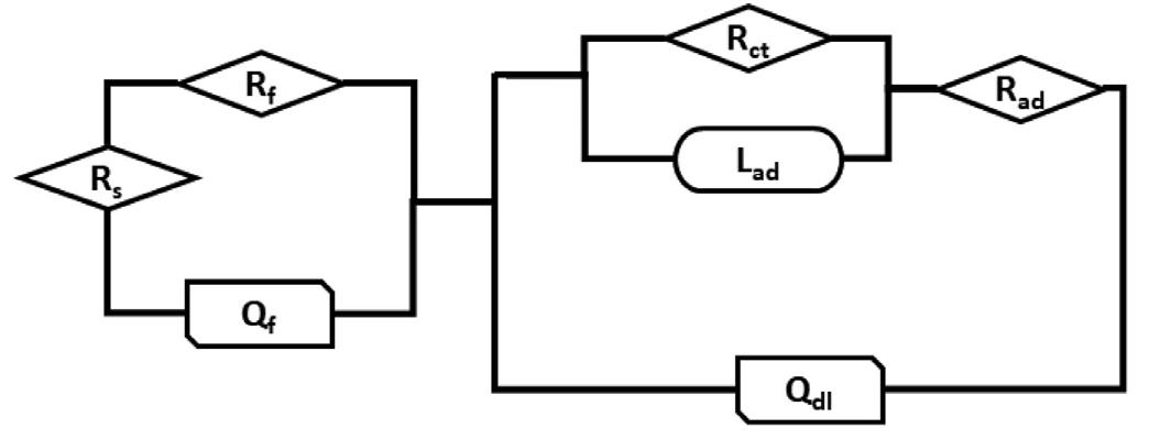
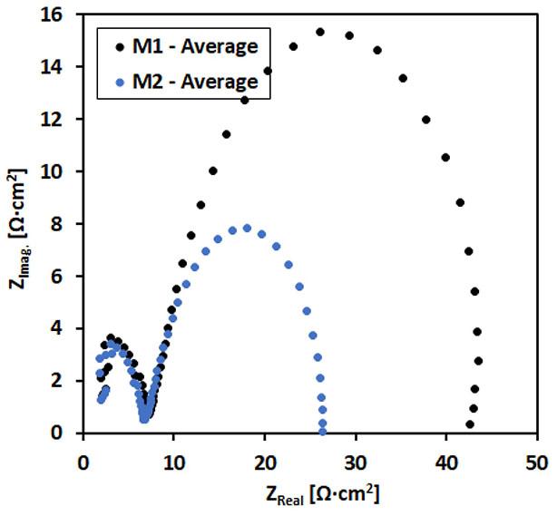
The resistance data are presented in Figure 10 and summarized in Table VII. In the EIS investigation M2 was more susceptible to corrosion than M1, as indicated by its lower Rad and Rct values. M1 and M2 had similar film resistance values.
The capacitance data are summarized in Figure 11 and Table VIII. Figure 11 illustrates that both mesh materials had similar double layer capacitance values, (Qdl). There was a difference in the value of the film capacitance, (Qf ), indicated in Figure 11 and Table VIII, suggesting the film on M2 might be thicker and porous in nature and hence, less protective than the film formed on M1.

Comparison of EIS for M1 and M2 mesh samples for 1 h
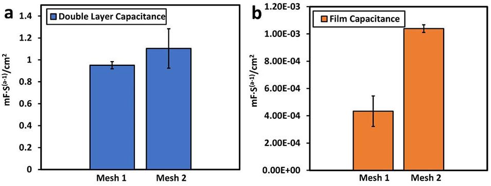
Anodic and/or cathodic polarization is a technique wherein the potential of the electrode is varied at a selected rate by the application of a voltage ramp with time and the resultant current is measured. Potentiodynamic anodic polarization (AP) measurements were performed in accordance with ASTM G5 (2014). The results of the potentiodynamic AP analysis for the two meshes (M1 and M2) are presented in Figure 12 and Table IX. This series of AP tests indicated that the Ecorr values determined in anodic polarization testing follow the same trend as that observed earlier for OCP measurements, i.e., M2 has a lower value than M1. The corrosion rates of M1 and M2 are statistically very similar but M2 is again slightly more susceptible to corrosion than M1, consistent with the earlier LPR measurements of corrosion rate.
Based on the relative performance in the undertaken accelerated corrosion tests, the M1 mesh is less susceptible to corrosion than M2 as seen by its higher OCP value, lower icorr in LPR, and higher Rct in EIS. The difference in performance is statistically significant and is attributed to lower carbon and silicon content and slightly higher Ni and Cu content compared to M2. This has significant implications if the mesh is installed in an aggressive corrosion environment. Corrosion of the mesh strands can result in reduced capacity and localized failure that may compromise the integrity of the primary surface support. The implication is that unless the area is rehabilitated, the mesh will be the weak link in the ground support system and can potentially result in a fall of ground.
The mine was also investigating the corrosion potential of mesh straps when exposed to an aggressive environment. Again, the mesh straps were identified as S1 and S2.
Open-circuit potential (open cell potential)
The results of the OCP, conducted in accordance with ASTM G5-14,
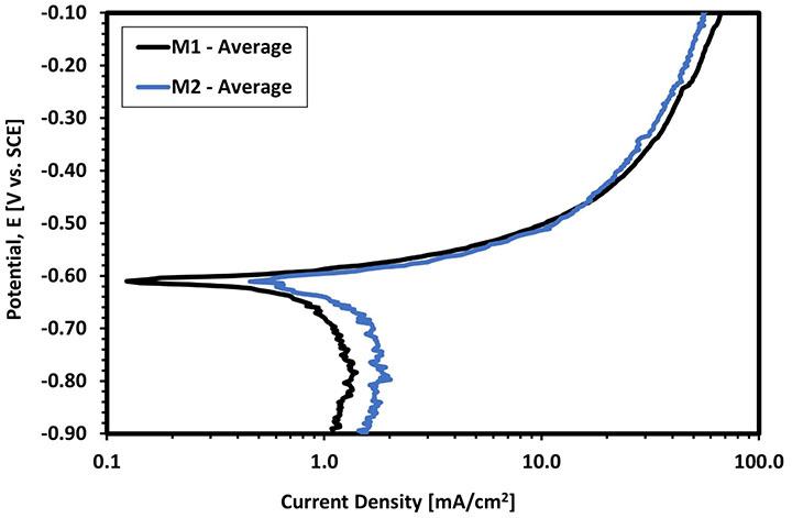
IX Potentiodynamic polarization for the mesh samples
Note:
2014, are summarized in Figure 13 where it can be seen that the OCP of S1 is lower than that of S2 indicating that S1 is more active than S2. An interpretation of the relative performance of the mesh straps is possible by reference to their chemical composition given in Table I.
In general, a higher Mn content should improve corrosion resistance as it decreases the corrosion rate (less negative OCP value). Similarly increased concentrations of C, S, and P content should decrease corrosion resistance, as these elements accelerate the corrosion rate (greater negative OCP value). Finally, the increased Cu and Ni content of S2 relative to S1 should improve the relative corrosion resistance, i.e., it decreases the corrosion rate (lower negative OCP value). In this investigation the higher beneficial Mn content of S1 is offset by the higher C, S, and P content along with lower Cu and Ni concentrations that resulted in the decreased corrosion resistance of S1 relative to S2.
LPR measurements were performed in accordance with ASTM G5997 (2014). The results are illustrated in Figure 14. The S2 mesh strap is less susceptible to corrosion than the S1. The linear polarization potential for S2 being Rp = 39.6 Ω·cm2 compared to Rp = 31.3 Ω·cm2 for the S1 mesh strap and the corresponding corrosion rates are given in Table X. This agrees with the predicted corrosion behaviour of the OCP values of the two materials, where S2 was predicted to have the lower corrosion rate.
A series of EIS experiments were performed in accordance with ASTM G106-89 (2015). The same procedure and equivalent circuit analysis (Figure 8) were used as for the mesh. The results of the EIS Nyquist plot for each mesh strap material are shown in Figure 15. The resistance data are captured in the histogram in Figure 16 and Table XI. In the EIS investigation both mesh strap samples had statistically similar film and charge transfer resistance values. The only significant difference was the resistance of adsorbed species on the surface, with a higher value for the S2 mesh strap compared


Table X
Results of LPO analysis and estimated corrosion rate for the mesh straps
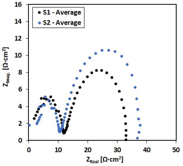
to S1. This is consistent with the trend observed for the mesh samples where the more corrosion resistant material had the higher resistance of adsorbed species.
Figure 17 and Table XII illustrate that both samples had similar double layer capacitance values, (Cdl), although there was a clear difference in the film capacitance (Cf). More charge is stored in the surface of the S2 mesh strap, which had better corrosion resistance compared to S1. This is inconsistent with the trend of Cf that was observed for the mesh samples.
Potentiodynamic anodic polarization
Potentiodynamic AP measurements were performed in accordance with ASTM G5 (2014). The results of the potentiodynamic AP analysis for the two mesh straps are presented in Figure 18 and Table XIII.
Table XI
Resistance data for S1 and S2 mesh straps
XII
Comparison of EIS for the two mesh strap samples for 1 h
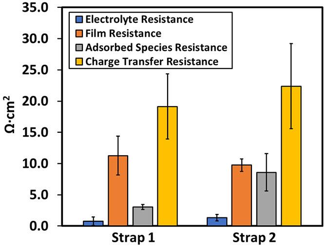
Figure 16—Comparison of electrolyte (Rs), charge transfer (Rct) and film (Rf ) resistance for the two mesh straps (S1 and S2)
The provided mesh straps were subjected to a series of accelerated corrosion tests in an aggressive corrosion environment. There was consistent repeatability in the results from all accelerated tests and indicate that the S1 mesh strap was less corrosion resistant than the
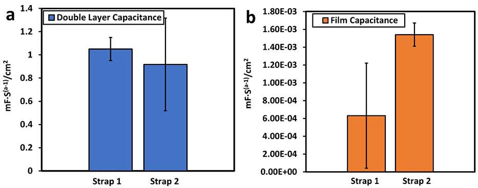
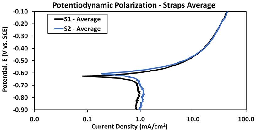
equivalent S2 mesh strap as evident by its more active OCP, and the higher corrosion rate determined in both LPR, and AP testing. This is reflected in the higher corrosion rates.
Primary and secondary surface support are integral parts of a successful ground support system. As part of ground support optimization, it is necessary to explore the use and interaction of different products. The qualification of new products requires a rigorous QA/QC process.
This investigation aimed to identify potential differences in long term performance of steel mesh and mesh straps when exposed to an aggressive environment. Accelerated corrosion techniques were employed to establish a relative ranking of mesh and mesh straps products when exposed to the same aggressive corrosive environment. All tests yielded consistent and repeatable results for both mesh and mesh straps.
The accelerated corrosion studies clearly demonstrated that the difference in performance between the #6 mesh samples from different suppliers was significant. The practical implication is that in an aggressive corrosion environment this will result in a significant reduction in the strand, and consequently, mesh capacity.
A difference in their susceptibility to corrosion was also observed when comparing the S1 and S2 mesh strap samples. The practical implications of this however may not be as significant as for the mesh, as the variations in performance were not as critical. This investigation highlights the need for strict QA/QC on provided ground support elements particularly when comparing elements from different sources. It is also demonstrated that the steel chemistry has a significant impact on the anticipated corrosion when exposed to aggressive environments.
Mesh and mesh straps are only two elements of a ground support system. In practice, failure of any reinforcement or surface support element, can lead to a compromised system. Although degradation in the performance of mesh and mesh straps over time will be dictated by multiple factors, corrosion can be a significant contributing factor. This paper demonstrates that there can be important variations between different mesh and mesh straps products exposed to an aggressive corrosive environment. Typically, a ground support system will employ mesh as its primary surface support. If higher loads and larger deformations are anticipated, the addition of mesh straps will result in better load distribution and improved performance. The presented accelerated corrosion investigations however identified significant variations
Potentiodynamic polarization for the
in the long-term performance between mesh and mesh straps. All other factors being equal, the choice of steel for the mesh suggests that in the same environment it would corrode faster than the mesh strap.
The practical implication is that the greater susceptibility to corrosion of mesh compared to mesh straps, is likely to result in earlier failure challenging the integrity of the ground support system. In effect it may be necessary to rehabilitate the primary surface support at an earlier time than the secondary surface support. These should be taken into consideration when determining the true costs of ground support over a longer working life.
Acknowledgements
The authors would like to acknowledge the excellent collaboration from Lac des Iles Mine of Impala Canada Ltd.
References
ASTM A1064/A1064M-22. 2022. Standard specification for carbonsteel wire and welded wire reinforcement, plain and deformed, for concrete. ASTM International, West Conshohocken, United States
ASTM E18-22. 2022. Standard test methods for Rockwell hardness of metallic materials. ASTM International. West Conshohocken, United States.
ASTM E1019‐11. 2011. Standard Test Methods for Determination of Carbon, Sulfur, Nitrogen, and Oxygen in Steel, Iron, Nickel, and Cobalt Alloys by Various Combustion and Fusion Techniques. ASTM International, West Conshohocken, United States.
ASTM E1479–16. 2016. Standard Practice for Describing and Specifying Inductively Coupled Plasma Atomic Emission Spectrometers. ASTM International, West Conshohocken, United States.
ASTM G3-14. 2014. Standard Practice for Conventions Applicable to Electrochemical Measurements in Corrosion Testing. ASTM International, West Conshohocken, United States.
ASTM G5–14. 2014. Standard Reference Test Method for Making Potentiodynamic Anodic Polarization Measurements. ASTM International, West Conshohocken, United States.
ASTM G59-97. 2014. Standard Test Method for Conducting Potentiodynamic Polarization Resistance Measurements, ASTM International, West Conshohocken, PA 19428‐2959, United States.
ASTM G106-89. 2015. Standard Practice for Verification of Algorithm and Equipment for Electrochemical Impedance Measurements. ASTM International, West Conshohocken, United States.
Baek, B., Karampinos, E., Hadjigeorgiou, J. 2020. Understanding the Impact of Test Configuration on Welded-Wire Mesh Laboratory Test Results. Rock Mechanics and Rock Engineering. vol. 53, no. 11, pp. 4873-4892.
Dorion, J.F., Hadjigeorgiou, J. 2014. Corrosion considerations in design and operation of rock support systems. Mining Technology (TIMM A), vol. 23, no. 2, pp. 59–68.
Dorion, J.F., Hadjigeorgiou, J., Ghali, E. 2010. Influence of corrosion rate on the capacity of rock support, ARMA 10-259, American Rock Mechanics Association. Proceedings 44th US Rock Mechanics Symposium and 5th U.S.-Canada Rock Mechanics Symposium, 27–30 June 2010, Salt Lake City, UT.
Hadjigeorgiou, J. 2016. Rock support: degradation and failure. Ground support 2016, the Eighth International Symposium on Ground Support in Mining and Underground Construction, Luleå, Sweden, E. Nordlund, Jones TH, Eitzenberger A (eds), p. 22.
Hadjigeorgiou, J., Potvin, Y. 2011. Hard Rock Ground Control with Screen and Shotcrete. Chapter 8.6. SME Mining Engineering Handbook. Society of Mining Engineers. pp. 573–594.
Hadjigeorgiou, J., Stacey. T.R. 2018. Challenges in determining the capacity of mesh. AusRock 2018: The Fourth Australasian Ground Control in Mining Conference, Sydney, NSW, 28–30 November 2018, pp. 280–290.
Hadjigeorgiou, J., Savguira, Y., Thorpe, S.J. 2020. Impact of Steel Properties on the Corrosion of Expandable Rock Bolts. Rock Mechanics and Rock Engineering, vol. 53. pp. 705–721.
Hadjigeorgiou, J., Thorpe, S.J., Cole, K.M. 2023. Quality Assurance Considerations for Friction Rock Stabilizers. Mining Technology (TIMM A). vol. 132, no. 1, pp. 17–29.
Hassell, R., Villaescusa, E., Ravikumar, A., Cordova, M. 2010, ‘Development of a corrosivity classification for weld mesh support at Cannington Mine’, in P Hagan & S Saydam (eds), Proceedings of the Second Australasian Ground Control in Mining Conference, The Australasian Institute of Mining and Metallurgy, Melbourne, pp. 1–5.
ISO 18265:2013. 2013. Metallic materials - Conversion of hardness values. Geneva: International Organization for Standardization (ISO).
Player, J.R., Morton, E.C., Thompson, A.G., Villaescusa, E. 2008. Static and dynamic testing of steel wire mesh for mining applications of rock surface support. T.R. Stacey and D. Malan (eds). Proceedings of the 6th International Symposium on Ground Support in Mining and Civil Engineering Construction, The South African Institute of Mining and Metallurgy, Johannesburg, pp. 693–706.
Tannant, D. 1995. Load Capacity and Stiffness of Welded-wire Mesh. Proceedings of the 48th Canadian Geotechnical Conference. Vancouver, Canada, pp. 729–736.
Wu, S., Northover, M., Craig, P., Canbulat, I., Hagan, P.C., Saydam, S. 2018. Environmental influence on mesh corrosion in underground coal mines. International Journal of Mining, Reclamation and Environment, vol. 32, no. 8, 519–535. u
Affiliation:
1Confucius Institute, University of Zambia, Lusaka
2University of Zambia, School of Mines, Department of Mining Engineering, Lusaka
Correspondence to: B. Besa
Email: bundabesa@yahoo.com
Dates:
Received: 4 Nov. 2020
Revised: 23 Apr. 2021
Accepted: 20 May 2024
Published: September 2024
How to cite:
Nalukui, S. and Besa, B. 2024. Effects of tailings disposal on the environment: A case study of Nampundwe Mine. Journal of the Southern African Institute of Mining and Metallurgy, vol. 124, no. 9. pp. 527–534
DOI ID:
http://dx.doi.org/10.17159/24119717/1417/2024
ORCID: B. Besa
http://orcid.org/0000-0001-9133-592X
by S. Nalukui1 and B. Besa2
Abstract
Globally, the demand for mineral products is ever increasing. Extraction of these mineral resources results in the continuous production of a huge volume of waste material, including tailing dumps. The mass of tailings usually exceeds the actual resource and often contains hazardous contaminants. This study investigated the effects of tailings disposal on soil, water, and air quality in the Nampundwe area. Water, soil, and dust samples were collected from different locations in the surrounding communities. The constituents analysed in the samples included copper, cobalt, iron, sulfate, and silica. According to the results obtained, some seepages occurred from the tailings impoundment to the shallow aquifer in the area. However, the general water quality meets the Zambia Environmental Management Agency (ZEMA) statutory limits. Recorded concentrations of sulfate (1500 mg/l), copper (1.5 mg/l), cobalt (1.0 mg/l), iron (2.0 mg/l), and silica were between 0.003 mg/l and 705 mg/l, which is far below ZEMA’s statutory limit. Silica concentration was also evident in the air. The highest concentration recorded was 260 ppcc (particle per cubic centimeter) recorded in July 2019 from the northern direction of the tailings dam. The concentration was below the statutory limit of 350 ppcc. The topsoil from the northern part of the tailings recorded a silica dust concentration of 39.9 ppcc. Iron was evident in the underground soil with a concentration of 8.01 ppcc, cobalt 0.005 ppcc, copper 0.051 ppcc, while sulfate was recorded as 0.41 ppcc.
Keywords environment, tailings, seepage, disposal, pollution, contaminant
Introduction
To achieve rapid economic growth, the world has resorted to activities such as mining, which leads to the exploitation of natural resources. As we may all be aware, mining is an important economic activity that has the potential to contribute to the development of many countries. In Zambia, the mining sector plays a vital role in the development of the economy. It accounts for 12 percent of the GDP. Over the past 50 years, Zambia has been successful in attracting investors into its mining sector. Despite the benefits from mining activities, mining activities in Zambia have an enormous environmental impact (Muma et al, 2020). This has emanated from mining and processing activities by the mining companies as well as the disposal of mine waste, especially tailings in the environment. This has long-term effects on the natural environment as well as the people in the surrounding communities (Besa et al., 2019). According to Awudi, 2000, despite these positive indicators, the role of the mining industry in the economic development of any country is questionable. The gains from the sector in the form of increased investment are being achieved at a great cost to the environment, health, and social wellbeing of the people in the surrounding communities, recording a series of public complaints against the mining companies operating in Zambia. According to Hudson, 2012, the major environmental problems arising from mining activities are land degradation, soil contamination, air pollution, surface, and groundwater pollution.
This study was conducted at the Nampundwe mine area in the Central Province of Zambia. The Nampundwe mine is the most southerly of the Konkola Copper Mines (KCM) operations. It is located 48 km to the west of Lusaka (Figure 1). Mine-associated infrastructure occupies an area of approximately 9 ha, while the mining license area covers 950 ha. Nampundwe area was once a forest and agricultural area before mining activities commenced. It is surrounded by communities that consist of approximately four hundred (400) households with roughly eight (8) people per household. Kacheta stream is the main surface water in the area and flows through the mine area, which is the main source of water to the community. The Nampundwe mine township is 2.5 km to the southwest of the mine. The area has a population of about 3500 people.

The Nampundwe mine operates an underground pyrite mine and concentrator. The pyrite from the Nampundwe mine is typically used as a blending material with copper concentrate for smelting. The ore from underground is hoisted directly onto the concentrator shaft bin for primary crushing before it is conveyed through the 120-tonnes/hour belt for secondary crushing. The mining method employed at the Nampundwe mine is conventional sublevel open stoping.
Materials and methods
Conceptual framework
The conceptual framework (Figure 2) used for the study illustrates the environmental and health impacts of mine tailings disposal on the environment. It shows the impact of mine tailings disposal on the environment and the health of people, according to the available literature.
Tailings production and disposal at Nampundwe Mine
According to Ritcey (2005), tailings are the major mine solid waste produced in the process of mineral beneficiation. With the development and utilization of mineral resources, the production and disposal of tailings have become an important factor in the sustainable development of the mining industry and endangering mining and the surrounding area’s ecological environment. Tailings are a waste product that has no financial gain to a mineral operator at that point in time. Not surprisingly, it is usually stored in the most cost-effective way possible to meet regulations and site-specific factors. They often consist of chemicals from processing plants as well as fine particles suspended in water. These have the potential to damage the environment by releasing toxic metals into the environment through erosion and surface runoff from the tailings into nearby water bodies (Blight, 1998).
In the past, when mines just started to operate in Zambia around the 1930s, river dumping was the most convenient way of disposing of tailings. This disposal system led to widespread environmental impacts in mining areas. This was nominally acceptable in earlier eras, but human production of mine tailings has increased by several orders of magnitude in the modern age, making such methods unacceptable to many societies (Blight,

1998). At Nampundwe mine, the tailings are pumped as slurry to the tailings dam situated 700 metres to the south of the plant. The slurry is discharged from a spigot that is moved around the perimeter of the facility and the walls are raised using the tailings.
According to Vick, (1983), the disposal of tailings is commonly identified as the single most important source of environmental damage by any mining operations. This is not surprising when considering that the volume of tailings requiring storage can often exceed the in-situ total volume of the ore being mined and processed. Over the last century, the volumes of tailings being generated at Nampundwe mine have increased dramatically as the demand for minerals and metals has enlarged. Nampundwe mine tailings are frequently stored in tailings dams, also known as tailings storage facilities, indicated in Figure 3.
Prevention and control of surface runoff from the plant area to the surrounding environment and minimizing dust generation are important considerations for the receiving environment illustrated at Nampundwe mine in Figure 4.
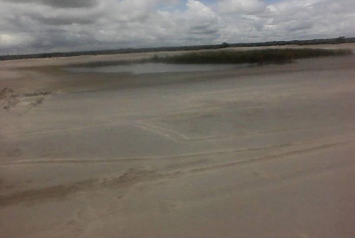
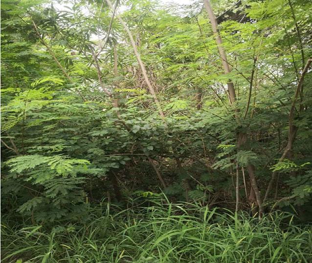
The study involved the collection of water, air, and soil samples from various points of the study area following the specific objectives. Soil, water, and air samples were collected randomly (to eliminate systematic bias and for equal opportunity of being chosen as a part of the sampling process) over time from the direction of the prevailing up-winds at the time of sampling, as there were more particles blown due to the wind direction. The Toxicity Characteristic Leaching Procedure (TCLP) was used to determine the elements that were present in the samples collected.
Twenty (20) water samples were collected randomly (to eliminate systematic bias and for equal opportunity of being chosen as a part of the sampling process) from Nampundwe township, Kacheta stream, village boreholes, village wells, monitoring boreholes near the tailings dam, and the tailings dam overflow. Figure 5 indicates the location of water sampling points in the Nampundwe area. All samples were collected and stored in 750ml sampling bottles before testing and analysis.
Water samples were collected from the upper, middle, and lower streams of the Kacheta stream (Figure 6). The upper stream provides the level of concentration before the stream passes through the mine area while the samples from the middle and lower stream will provide the level of concentration from the mine and after the mine respectively.
There are four (4) monitoring boreholes around the tailings dam, which are used by the company to monitor the level of contamination from the tailings dam. The water quality monitoring data collected indicated that the pH level was between 7 and 8, sulfate presented an average of 445−505 mg/l, iron 0.8, and other dissolved metals were present at low concentrations. Water samples were also collected from the monitoring boreholes around the Nampundwe mine (Figure 7).

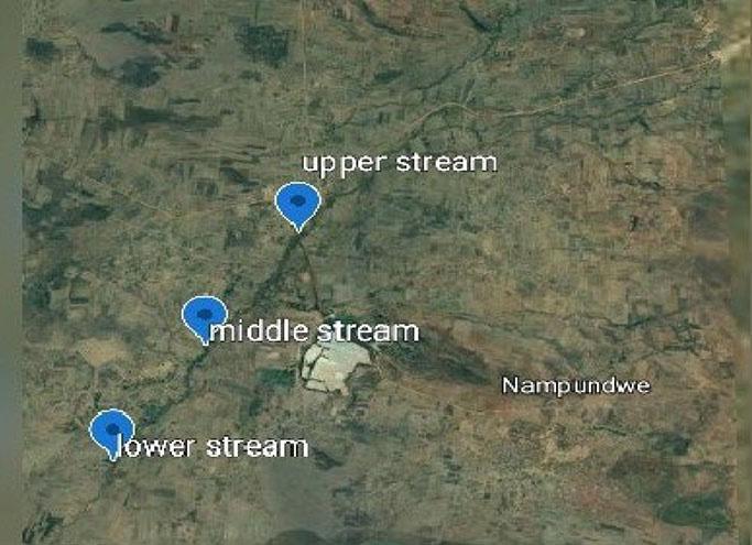

Figure 8 shows the over-flow water from the tailings dam at Nampundwe mine. The overflow water is released into the Kacheta stream through the toe drain. There are filter drains installed in the dam walls, which also flow to the decant drain. One (1) water sample was collected from the tailings dam overflow/decant drain to determine the quality of water discharged into the water system from the tailings dam. The water quality monitoring data collected indicated that the pH level was between 7 and 8, sulfate exhibited an average of 1011 mg/l, iron 0.1, and other dissolved metals were present at low concentrations.
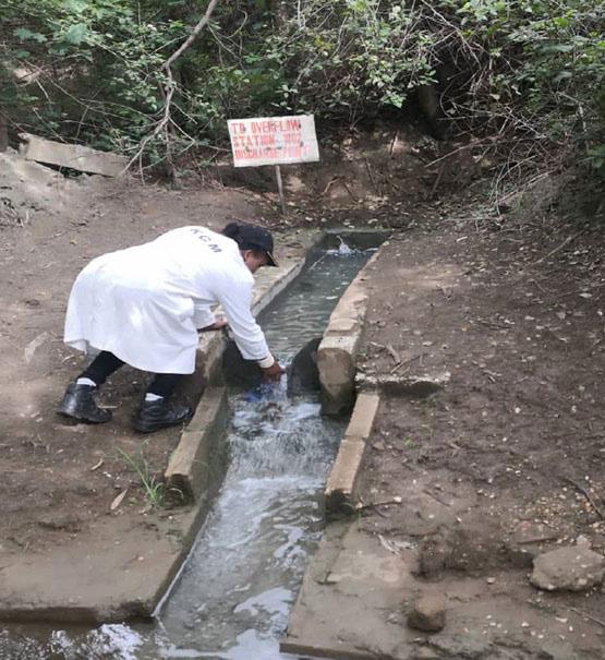
Twenty-one (21) soil samples were collected from different locations according to the direction of the prevailing up-winds in August 2019 during the dry season. The soil was sampled from Shanide village, ranging between 0.5 km and1.5 km from the mine, Shamoonga village, which is situated between 1.5 km to 3 km from the mine, Sichobo village ranging between 0.5 km and 1.5 km from the mine, and Shakemba village being situated 1.5 km to 3 km away from the mine area. Other soil samples were collected during the rainy season in December 2019 from Shakainge village, which is situated 0.5 km to 1.5 km away from the mine, Northern Mwanachindalo, situated 1.5 km to 3 km away, and Nampundwe township, approximately 1.5 km to 3 km away from the mine. Kombo and Tromp (2006) state that random sampling is a part of the sampling technique in which each sample has an equal probability of being chosen. A sample chosen randomly is meant to be an unbiased representation of the total population. Soil samples were collected from the depth of 30 cm (topsoil), 60 cm (middle soil), and 90 cm (ground soil), culminating in a total depth of 90 cm. The samples were collected by using a standard auger and were stored in sample bags. The sample bags were tied using a string to avoid cross-contamination and were labeled according to the sampling points, whereafter the samples were taken to the lab for testing. Figure 9 shows a satellite map demonstrating the soil sampling locations. The mine commenced operations in 1913 and, at the time, was known as the King Edward mine. At that stage there was no pollution, hence no background data was obtained for soil contamination.
The dust samples were collected from the northern, southern, eastern, and western parts of the tailings dam. The samples were collected using dust samplers from January 2019 to December 2019. This was done to determine the amount of silica dust from the tailings that were present in the air.
Water and soil samples were analysed by means of the Atomic Absorption Spectrometer (AAS) at the University of Zambia, School of Mines Geo-Chemical Analytical Laboratory (Figure 10). The AAS is a tool that was used to analyse the metal concentration
in the samples. The elements that were analysed included cobalt (Co), copper (Cu), iron (Fe), silica, and sulfur (S). Air samples were collected over a period of one (1) year to obtain representative samples from all three (3) main seasons of the year (cold, hot, and rain). Air samples were also analysed at the University of Zambia, School of Mines Geo-Chemical Analytical Laboratory.
The results from the study indicate that the soil, water and air samples obtained from the study area indicated the presence of sulfate, copper, cobalt, iron and silica, of which the recorded concentrations were below the ZEMA’s statutory limit, being: Sulfate (1500 mg/l), copper (1.5 mg/l), cobalt (1.0 mg/l), and iron (2.0 mg/l). The statutory limits exist to determine whether the elements tested exceed the allowable standard or limit for polluting. The results from the study indicate that all element concentrations were below the statutory limits, except for iron, which recorded higher concentrations in the water, i.e. between 4.05 mg/l and 5.18 mg/l in some areas. However, background levels of iron in the water of the area were between 0.3 mg/l and 1.9 mg/l. Hence, it is worth noting that the higher concentration of iron in the samples tested and analysed should not only be attributed to the mining activities, but also as a naturally occurring element most likely to be present in all the soil, as it is an essential element for plant growth.
Water sampling results
It was observed that there were significant differences in the concentrations of elements contained in the water according to the

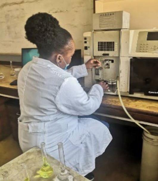
sampling points. All the water samples tested and analysed were compared to the Zambia Environmental Management Agency (ZEMA) statutory limits as indicated in Table I. This was done to give a clear picture of how the actual findings compare with the ZEMA statutory limits. ZEMA ensures that mining companies undertake their operations in line with the laws. The agency monitors the element concentration within the Nampundwe area from time to time. Table I, includes the information for the ZEMA statutory limits.
According to water sampling results (Figure 11), it is evident that all element concentration levels from all the samples tested and analysed were below the ZEMA statutory limits. However, iron was recorded at 4.38 mg/l in the middle of the Kacheta stream. The iron concentration exceeded the statutory limit of 2.0 mg/l. The pH level ranged between 5.5 to 6.8, whilst the TDS levels were between 1300 mg/l to 1500 mg/l. The water quality monitoring data collected indicated that the pH level was between 7 and 8, Sulfate exhibited an average of 445-505 mg/l, whilst other dissolved metals were present in low concentrations.
It is also evident from the results of water sampling from the village boreholes (Figure 12) that the concentration of all elements in the water obtained from all the village boreholes was below the ZEMA statutory limits. Furthermore, the depth of the boreholes was in the range of 30 metres to 90 metres, where the land had a slight slope and the distance ranged between 0.5 km to 3 km far from the tailings storage facility (TSF) respectively.
In addition, it was found out that all element concentrations recorded from all the village wells sampled, were below the ZEMA statutory limits (Figure 13). However, iron exhibited a higher concentration of 5.18 mg/l, which was in excess of the ZEMA statutory limit of 2.0 mg/l. The higher concentration was also attributed to the natural formation of iron within the Nampundwe area, and the depth of the wells being in a range of 10 metres to 25 metres, where the land has a slight slope and the distance is 0.5 km to 3 km far from the tailings storage facility (TSF) respectively.
All element concentrations recorded from the township boreholes (Figure 14) were also below the ZEMA statutory limit and the depth of the boreholes were in a range of 30 metres to 90 metres, where the land has a slight slope. There the distance was 0.5 km to 3 km far from the tailings storage facility (TSF), respectively.
Additional findings indicated that the concentration of all the elements recorded (Figure 15) was below the ZEMA statutory limits, except for iron, which recorded 4.05 mg/l from the sampling borehole 1. The concentration recorded was higher than the ZEMA statutory limit of 2.0 mg/l, but it was also attributed to the naturally
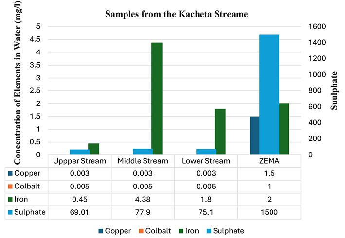


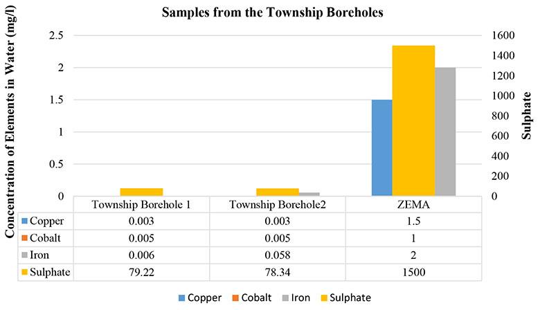
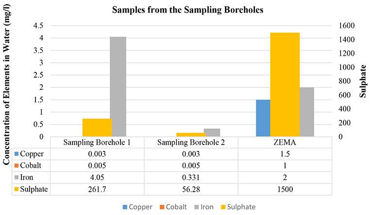
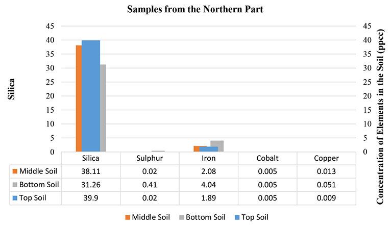
occurring element present in the Nampundwe area. The depth of the boreholes was in a range of 30 metres to 90 metres, where the land has a slight slope. There are monitoring boreholes around the tailings storage facility (TSF) to monitor the amount of element concentration that could be present within a distance of 0.5 km to1.5 km far from the TSF, respectively.
Sampling results revealed that the soils in the Nampundwe area exhibited the presence of Sulfur, iron, and silica. In relation to Figure 16, silica represented the highest concentration as compared to other metals because the wind was blowing in the northern direction of the tailings at the time of sampling. In addition, the particles were being moved in a northern direction by the running water resulting from the rains. All the levels of soil from the northern part of the tailings recorded the presence of silica, Sulfur, and iron as shown in Figure 16.

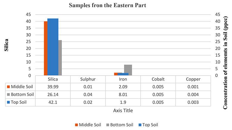
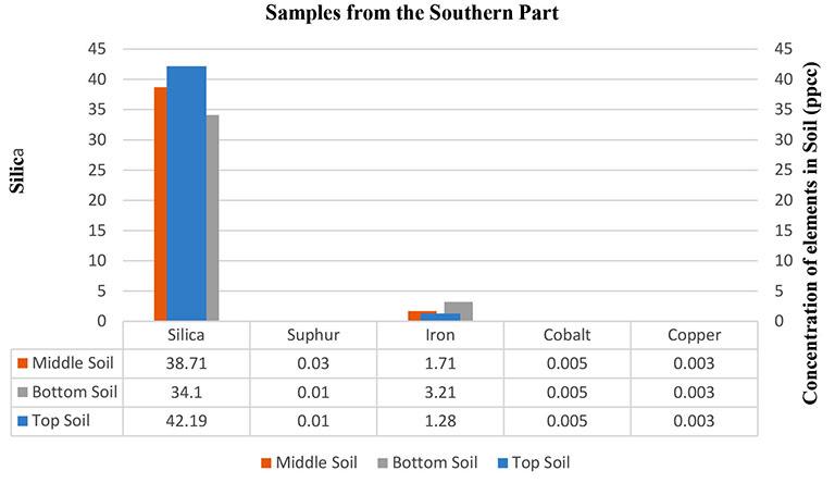
In the western part of the tailings, results in Figure 17 show that silica and iron were present in all the levels of soil.
The eastern part of the tailings also recorded the presence of iron and silica (Figure 18) in all the levels of the soil.
The southern part of the tailings recorded concentrations of silica and iron in all the levels of the soil as can be seen in Figure 19.
According to the results (Figure 20) the concentration of silica dust was recorded in July 2019 with 260 ppcc as the highest recording in the northern direction of the tailings. This was the direction of the prevailing up-winds at the time of air sampling and was closer to the tailings compared to the eastern, western, and southern directions. During this period, it is usually dry and windy, and this results in high emissions of silica dust. The highest recorded concentration of 260 ppcc did not however, exceed the statutory acceptable standard of 350 ppcc. From the dust sampling results recorded during the month of December, it can be seen that concentration decreased to
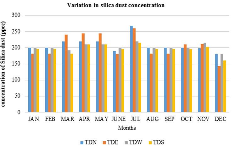
180 ppcc in the northern direction. During this period there was very little silica dust concentration as it was during the wet season of the year.
Conclusion
In as much as we acknowledge the economic benefits of mining activities in Zambia, there is a need to recognize the environmental impacts that are associated with it to find ways to mitigate and manage them. After an investigation into the problem as it pertains to the Nampundwe mine and the surrounding community, it has come to light that, despite the mining activities, the general water, soil, and air quality meets the statutory limit requirements. Kacheta, which is the major stream in the area, recorded concentrations of all the tested elements. It was observed that all the elements, except for iron, which was recorded at 4.38 mg/l in the middle stream (situated adjacent to the tailings dam), were below the statutory limit. This concentration of iron exceeded the statutory limit of 2.0 mg/l. Results from the village wells indicated a low concentration of the elements, except at village well 5, which recorded the highest iron concentration i.e., 5.18 mg/l. The concentration of iron at village well 5 exceeded the ZEMA statutory limit of 2.0 mg/l. All elements from the township boreholes showed low concentrations that were below the ZEMA statutory limit. As mentioned earlier, it is worth noting that the higher concentration of iron in the samples tested and analysed may not only be attributed to the mining activities, but also as a naturally occurring element most likely to be present in all the soil as it is an essential element for plant growth. Soil sampling results revealed that there was a presence of Sulfur, iron, and silica in the Nampundwe area. Furthermore, it was observed that the concentration of iron, silica, and Sulfur had no major effect on the soils in the Nampundwe area. According to the results, the concentration of dust was recorded as being higher in July 2019 with 260 ppcc in the northern direction. However, the recorded concentration of 260 ppcc did not exceed the statutory acceptable standard of 350 ppcc. The dust sampling results recorded during the month of December, revealed that the concentration decreased to 180 ppcc in the northern direction as this was during the wet season of the year.
Furthermore, in the event where the element concentration exceeded the statutory limit, Nampundwe mine sought to institute
certain measures to curtail and mitigate the environmental, health, and other effects on people. Measures that have been put in place include reforestation of degraded lands, reviewing the operation methods, establishment of a health facility within the area for the benefit of both workers and residents within the communities, and the institution of health education programmes for the benefit of the people. Furthermore, the mine is working hand in hand with the ZEMA, which ensures that mining companies undertake their operations in line with the laws. The agency monitors the element concentration within the area from time to time.
(i) Stringent and rigorous efforts to bring about reforestation and other measures aimed at restoring degraded lands to their original state after mining activities, should be intensified by the company. The land would be available especially to farmers for cultivation purposes. Also, employment opportunities will receive a significant boost to reduce the high rate of unemployment in the region.
(ii) Nampundwe mine should provide alternative sources of potable drinking water, such as from boreholes. However, in support of this exercise, there should be intensive education of the people in the surrounding areas to comprehend the need for them to utilize the potable water rather than the poor-quality surface water sources.
Water from Several dug wells are excessively consumed by local villages and are potentially at risk. It seems reasonable, therefore, to initiate regular monitoring of these sources. Monitoring data may support mine-community initiatives towards improved water supply for the local communities. Therefore, it is recommended that some of the existing shallow village wells, if retained for local use, should be monitored for water level, and organic and inorganic water quality.
I wish to express my appreciation to the Education for Sustainable Development in Africa (ESDA), which is funded by the Africa Development Bank (AfDB) for their financial support. I thank Dr Bunda Besa for providing overall project supervision and
administration. I thank most sincerely, the Management of Nampundwe Mine for their maximum co-operation and assistance. I also acknowledge all the dedicated lecturers of this programme, from the School of Mines, for their encouragement. I wish to recognize Sara Malamba and my superior at work, Dr Sande Ngalande who assisted in diverse ways. I also thank Richard Nyirenda for rendering selfless services and committed assistance during the sample collection stage.
Besa, B., Kabwe J., Asinja J., Banda W. 2019. Socio-economic impact of mine closure and development of exit strategy for rural mining areas in Zambia: A case study of Kalumbila District. International Symposium on Mine Planning and Equipment Selection. Springer International Publishing, pp. 411–421. Hudson, T. 2012. Living with Earth, An Introduction to Environmental Geology. PHI Learning Private Limited. Kombo, D.J. and Tromp D.L. 2006. Proposal and Thesis Writing:
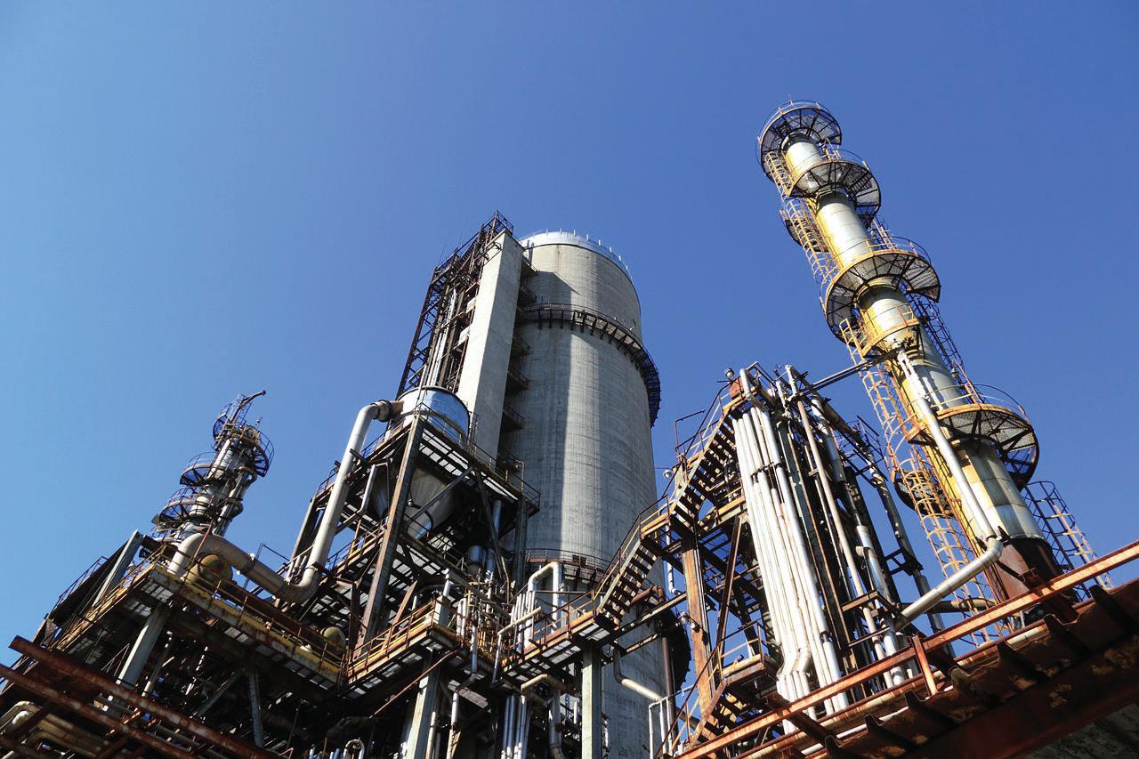

The School of Chemical and Minerals Engineering at North-West University (Potchefstroom Campus) offers an undergraduate qualification (NQF Level 8) that is approved and accredited by the Engineering Council of South Africa (ECSA).
Our BEng in Chemical Engineering degree incorporates specialised minerals processing modules that deal with the physical and chemical processes used to extract metals and other commodities from ores. These include diamonds, coal, precious metals (gold, silver, platinum, palladium), critical minerals (cobalt, graphite, lithium, manganese, and nickel), rare earth elements as well as base metals. The production, processing and export of these commodities is the largest contributor to South Africa’s foreign earnings. This sector is also one of the largest employers in the country.
Chemical Engineering in Mining and Minerals?
The role and responsibilities of a Chemical Engineer in the sector include the understanding and design of mineral processing systems
with a focus on safety, environmental sustainability, society, governance, performance monitoring, as well as innovatively addressing the various economic and technological challenges experienced by mineral processing plants in the era of the 4th Industrial Revolution (4IR). In terms of research our expert staff members specialise in the following areas (but not limited to):
• Hydrometallurgy with emphasis on energy storage systems
• Clean coal processing with emphasis on fine waste and discard coal repurposing
• Dry processing and dewatering of coal and other commodities
• Emissions control, especially in terms of particulates, sulphur (S) and carbon dioxide (CO2)
• Water treatment, mine wastewater treatment and pollution control
• Advanced modelling and simulation of systems using artificial intelligence (AI) i.e., machine learning, artificial neural networks (ANN) etc
• Other mineral processing using gravity separation
• Process safety and loss prevention
• Sustainable bioenergy and biotechnology
For more information, our personnel and how to apply click on the following link: https://engineering.nwu.ac.za/
Affiliation:
University of Toronto, Canada
Correspondence to:
J. Hadjigeorgiou
Email:
john.hadjigeorgiou@utoronto.ca
Dates:
Received: 16 Feb. 2024
Revised: 2 Jun. 2024
Accepted: 8 Aug. 2024
Published: September 2024
How to cite: Knox, G. and Hadjigeorgiou, J. 2024. Behaviour of paddled energyabsorbing rockbolts under complex loading laboratory conditions. Journal of the Southern African Institute of Mining and Metallurgy, vol. 124, no. 9. pp. 535–546
DOI ID:
http://dx.doi.org/10.17159/24119717/3294/2024
ORCID:
J. Hadjigeorgiou http://orcid.org/0000-0002-6047-3964
by G. Knox and J. Hadjigeorgiou
Abstract
Since their introduction in 2010, paddled energy-absorbing rockbolts have been widely used in seismically active hard rock mines. This paper provides new data and reviews previous work to quantify the performance of paddled energy-absorbing rockbolts under controlled laboratory conditions. Of significance is the realization that the typical split location in impact tests, at the centre between two paddle anchor points can at best provide an upper limit value. This inherent variability in performance under different testing configurations should be acknowledged and taken into consideration in the design of ground support in seismic conditions.
This paper discusses the reduction in capacity of paddled rockbolts as a function of loading angle from a maximum value during axial tests (0° loading angle) to the lowest value during pure shear (loading angle of 90°). A significant reduction in displacement capacity is observed as the loading angle changes between axial (0°) and 40°. Beyond a 40° loading angle up to shear (90°) loading the reduction in displacement capacity is less significant.
Due to the variances in the capacity observed through the variance of the testing configuration: loading mechanism, direction of loading, location / presence of a discontinuity, it must be recognized that results from laboratory-based testing are not independent of the testing configuration. This should be acknowledged when extrapolating anticipated performance in the field.
Keywords yielding ground support, paddled energy-absorbing rockbolts, impact testing configuration, combined axial shear loading
Introduction
Ground support is an integral component of risk management in all underground mining operations. A successful ground support strategy needs to meet specific design requirements and be cost effective while maintaining the stability and operability of an excavation for its anticipated service life. A successful ground support strategy matches the anticipated rock mass failure mode to the response of the ground support system. This is only possible if the rockbolt is successfully installed in what are at times adverse ground conditions.
Ground support technology has seen significant advancements in the last two decades, particularly in the introduction of energy-absorbing or yielding rockbolts. The advantages of yielding rock reinforcement elements were identified by Ortlepp and his cohorts in the 1960s. Following a review of rockbolt performance in rockbursts, Ortlepp (1969) conducted an underground blast test and demonstrated that a ‘softer’ system, which is able to sustain loads over a large displacement maintained the operability of the excavation.
One of the earliest energy-absorbing rockbolts was the cone bolt. Originally developed in South Africa as a cement grouted rockbolt by Jager (1992), it was not used widely at mine sites until it was modified in Canada to be used with resin. The main difference in the modified cone bolt was the addition of a blade paddle that extends ahead of the conical head that spins in the resin as the bolt is inserted in the borehole, Simser et al. (2007). Although the modified cone bolt was successfully used at several operations it was apparent from both laboratory and field observations that it did not perform well when subjected to seismic loads following considerable static deformation, (Simser et al., 2007). Although variations of the cone bolt are still used at some operations, it has been superseded by the next generation of energy-absorbing rockbolts, including the paddled energy-absorbing rockbolt.
The first paddled energy-absorbing rockbolt, the D-bolt, was developed by Li (2010) as a multi-point anchor steel bar installed in a fully grouted borehole. A series of quasi-static tests demonstrated that the paddled energy-absorbing bolt had significantly higher maximum energy-absorption than rebar bolts,
(Li, 2010). The performance of the energy-absorption mechanism was also quantified through impact testing (Li and Doucet, 2012), with the rockbolt sustaining large displacements prior to rupture. These are the qualities necessary for a yielding rockbolt as advocated by Ortlepp (1969). Empirical evidence at early mining applications also demonstrated that the bolt performed well under seismic loads and is arguably the most popular energy-absorbing rockbolt used at seismically active mine sites.
Since the development of the original paddled energy-absorbing rockbolt, several reinforcement elements that use the same concept have been developed. These are now widely used as part of ground support systems for squeezing or burst-prone rock masses. A practical issue that contributed to the wide use of paddled energyabsorbing rockbolts is the use of similar installation procedures as conventional resin rebar rockbolts. The resin rebar rockbolts are typically efficient to install and offer reasonable corrosion protection when fully encapsuled within the resin.
A rockbolt is installed with the intention of maintaining the operability of an excavation for the service life. The installed capacity is determined through destructive laboratory-based testing loading the rockbolt with a singular loading mechanism. This paper provides new data on the performance of energy-absorbing paddled rockbolts as well as consolidating research into both the effect of altering the loading angle in quasi-static tests, and recognizing the influence of split location during impact tests on the performance of a paddled energy-absorbing rockbolt.
A successful rock reinforcement strategy requires a match between anticipated rock mass failure mechanisms and the desirable rock reinforcement behaviour, (Potvin and Hadjigeorgiou, 2020). This requires a good understanding of ground conditions as well as the performance of rockbolts under the anticipated loading. Where seismic or squeezing rock masses are anticipated, paddled energyabsorbing rockbolts are routinely used as part of the ground support system for both as designed and rehabilitationed excavations, as demonstrated in Figure 1.
There are challenges in determining both demand and capacity of the rockbolts, owing to the variability of the rock mass and complexity of the loading mechanisms. Li (2010) has provided several examples of rockbolt failures in high stress conditions, while Simser et al. (2007) and Stacey (2012), illustrated the complex loading mechanisms associated with seismic loads, (Figure 2). It is difficult to quantify the demand placed on the ground support
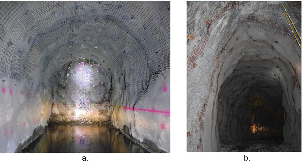
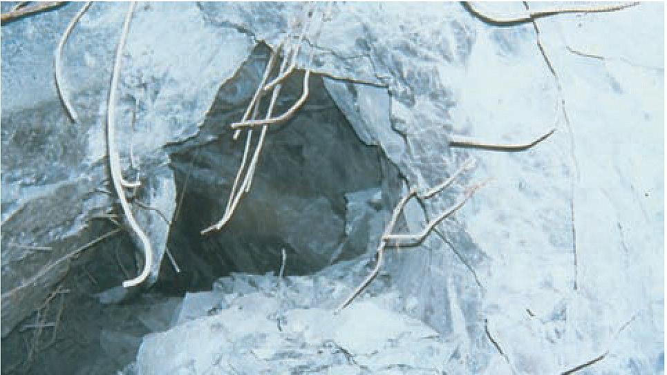
system under seismic conditions. Laboratory-based testing methods, such as impact testing have improved our understanding of the capacity of a rock reinforcement element subjected to a singular loading mechanism. The main limitation of the majority of laboratory experiments is that they focus on axial loading and, to a lesser degree, on shear loads. As illustrated by Windsor and Thompson (1997), using the dislocation and rotation of a wedge, as illustrated in Figure 3, rockbolts are often subjected to a loading combination consisting of tension, shear, and torsion.
The laboratory-based testing impact testing methodologies were developed in response to the increase in demand for energy-absorbing rockbolts as part of a risk mitigation strategy in seismically active mines. The method provides a controlled environment within which capacity quantification can be conducted at a relatively low cost. A comprehensive review by Hadjigeorgiou and Potvin (2011) identified several rock reinforcement and support testing facilities that had been constructed to quantify the capacity

of rockbolts under impact loads. Only a few of those were used on a routine basis at the time. Despite the inherent limitations of impact tests, test rigs can provide repeatable results and can perform a relatively large number of tests at reasonable cost, without interfering with mining operations. Since the benchmarking study by Hadjigeorgiou and Potvin (2011), several new impact facilities have been constructed and used on a routine basis. Li et al (2021) provided a comparative case study of tests conducted at different facilities in North America, Australia, Europe, and Africa and discussed the observed variations in the reported results. This comparative study illustrated the importance of understanding the inherent biases in the machines when comparing results generated on different machines. Beyond testing rig bias, a major limitation of the laboratory drop testing methodology is that it is an axial loading case that only captures one potential mechanism in a seismic event.
The use of large-scale shear tests has provided useful data and improved understanding of the effect of shear loading on the performance of rock reinforcement (Stjern, 1995; Chen and Li, 2015; Li, 2016; Knox and Hadjigeorgiou [2023a and 2023b]). In these series of experiments the rockbolts are installed in concrete blocks, which are independently driven to generate the desired loading conditions. The inclusion of the concrete blocks into the testing configuration is an improved representation of the in-situ loading configuration due to the strength differential between the rock reinforcement element and the host rock.
Due to the composite loading resulting from the interaction between the host rock at the perimeter of the borehole, the anchoring medium and rock reinforcement element, it is accepted that the shear displacement at a joint in the rock mass will result in a combination of bending and tensile loading of the rockbolt. This is well demonstrated in a physical modelling experimental programme conducted by Moyo and Stacey (2012) to demonstrate the performance of rock reinforcement elements in blocky ground (Figure 4). Two other important considerations are highlighted in the image: the angle at which the rockbolt intersects the joint and the fact that the rockbolt intersects multiple joints. The reality of the loading cases may, however, be significantly more complex as illustrated in Figure 2.
Paddled energy-absorbing rockbolts
Paddled energy-absorbing rockbolts are widely used in underground mines as part of the ground support system when the anticipated rock mass failure will result in either squeezing

or rockbursting. The base component of the rockbolt is the steel bar, into which one or more paddle sets and a threaded length are formed, as can be observed in Figure 5.
The ‘free length’ between the paddles sets or a paddle set, and the threaded portion is debonded from the anchoring medium (resin or cementitious grout) when a load is applied. The energy is dissipated through the plastic deformation of the steel bar between the paddle sets or threaded anchor bounding the joint or bulking rock mass. Therefore, when installed within a competent anchoring medium, the performance of the rockbolt is governed by the mechanical properties of the steel bar.
The installation procedure of a resin-anchored paddled energyabsorbing rockbolt is similar to that of a conventional resin rebar rockbolt, as illustrated in Figure 6. The resin cartridges are inserted into a pre-drilled borehole, and the rockbolt is subsequently inserted into the borehole. A rotation is applied to the rockbolt during the insertion process to facilitate the mixing of the resin by the paddle set. Thus, the purpose of the paddle set is twofold: mixing of the resin and anchoring of the tendon within the competent resin. Alternatively the rockbolt can be inserted into a borehole prefilled with cementitious grout.
Given that the original intent for the paddled rockbolt was to provide a high energy-absorbing rockbolt for seismically active conditions, it is not surprising that the focus was to undertake a series of impact tests to demonstrate and quantify its performance. In fact, it was often a prerequisite by several mining companies

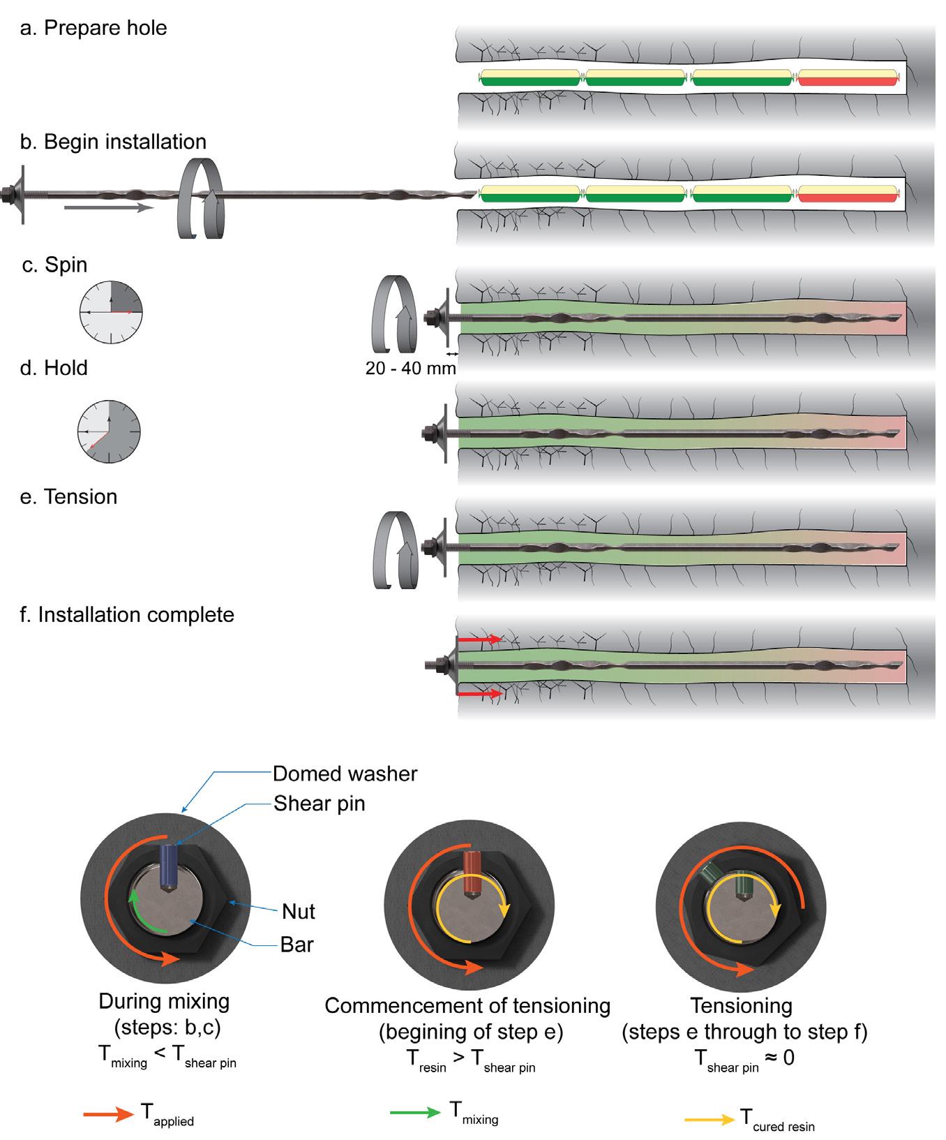
that suppliers provide data on new rockbolts under impact loads. Examples of impact tests for rockbolts using the paddled energy-absorbing concept are provided by Li and Doucet (2012), Villaescusa et al. (2015); Bosman et al. (2018), and Knox et al. (2018).
Compilations of impact tests from multiple rigs, e.g., Potvin and Hadjigeorgiou (2020) and Villaescusa et al. (2015), clearly illustrate that paddled energy-absorbing rockbolts have greater energy-absorbing capacity than conventional rockbolts. It is now recognized, however, that there is a degree of bias in every impact testing rig, (Li et al., 2021) that may influence the results. Consequently, there are advantages in comparing the results obtained using the same rig and testing protocol.
Influence of testing configuration on the performance of paddled energy-absorbing rockbolts under impact loading
Typically, the dynamic energy capacity of a paddled energyabsorbing rockbolt is determined through an indirect impact split tube test or in combination with a direct impact continuous tube test. The continuous tube configuration simulates the situation when the impact load is directly applied onto the bolt plate, while the split-tube setup aims to reproduce a load on the bolt when a rock block is ejected by an impact thrust, (Li et al., 2021).
It was originally assumed that the performance of the rockbolts under axial impact loads would be uniform across a given free
length. This was a reasonable assumption given a bolt design that facilitates the debonding or stretching of the bolt between the paddles.
Knox and Hadjigeorgiou (2022), used the Epiroc dynamic impact testing rig (DIT), illustrated in Figure 7, to conduct the only investigation into the effect of the testing configuration on the performance of the paddled energy-absorbing rockbolt. In this series of tests both the loading configuration (indirect vs direct) and the location of the split along the length of the paddled energyabsorbing rockbolt were allowed to vary. All rockbolt samples were prepared from a single batch of steel to limit variations in the mechanical properties of the steel. A total of five testing configurations were selected as shown in Figure 8, with variations of both the loading configuration and the split location. These represent different plausible loading configurations and load transfer mechanisms. The location of the rupture, total displacement at rupture, and energy dissipated at rupture were recorded following a series of 30 kJ drop tests.
The capacity of the paddled energy-absorbing rockbolt relative to the split location along the length of the rockbolt is illustrated in Figure 9. As anticipated, the direct impact continuous tube test (Figure 8a) loaded the shortest length of bar between the thread and the proximal paddle set, resulting in a significantly reduced capacity of the rockbolt. When the direct impact split tube test (Figure 8b) was used, it was anticipated that both the length of tendon between
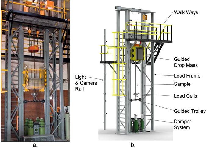
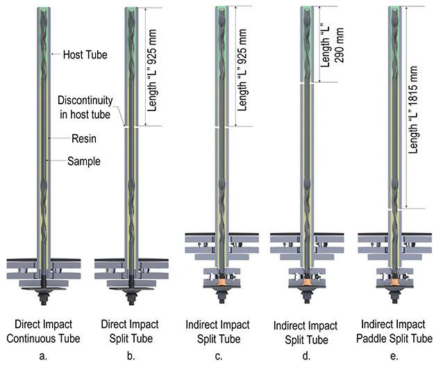
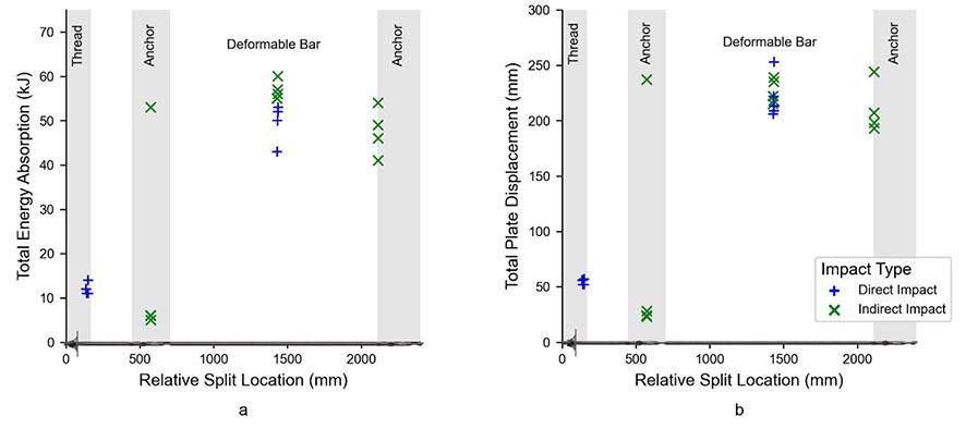
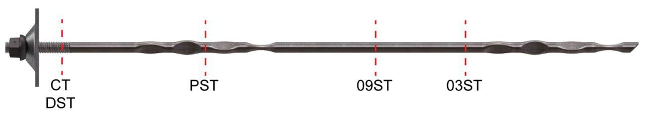
the thread and proximal paddle set and between the paddle sets would be mobilized, resulting in a higher impact capacity. However, as illustrated by the typical rupture location in Figure 10, during direct impact loading the load transfer mechanism is through the thread which has a lower capacity than the unmodified tendon. Consequently, due to the reduced capacity of the thread, it ruptures prior to the dissipation of the full plastic potential of the length between the two paddle sets. Thus, the capacity recorded when subjecting the rockbolt to a direct impact split tube test was less than the indirect impact split tube test (Figure 8a).
When the split was located within the paddle set (Figure 8e) a significant decrease in the capacity resulting from the reduced ‘free length’ of steel mobilized was recorded. Of interest was the effect of relocating the split: from the centre to the periphery of the deformable length between the two anchor points (Figure 8c, d). A decrease in the capacity was recorded (8.5%) when comparing the typical indirect impact split tube performance with the split centrally located (Figure 8c), to an indirect impact split tube test, which could be considered to be a short encapsulation impact test, as the split was located at the proximal end of the distal anchor set (Figure 8d). For both configurations the typical rupture locations observed was at the split location, with a length of tendon protruding from both segments as illustrated in Figure 11.
From the work presented by Knox and Hadjigeorgiou (2022), it can be concluded that the capacity of a paddled energy-absorbing rockbolt can vary significantly along the length of the rockbolt. A 90% variation in the capacity of the rockbolt was observed when the split location was changed as indicated in Figure 9 (a). The practical implication of these results is that ‘typical’ design values obtained from impact tests with the split located at the centre between two paddle anchor points at best provide an upper limit value. This inherent variability in performance under different testing configurations should be acknowledged and taken into consideration in the design of ground support in seismic conditions. The observed variation in performance as a function of split location can provide a plausible explanation for variations in field performance of paddled energy-absorbing rockbolts in rockburst events.
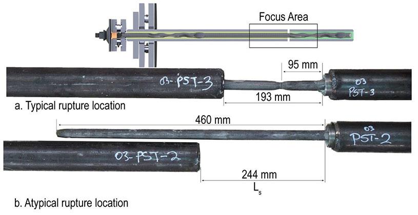
The advantages of conducting loading tests on rockbolts in a controlled environment are well recognized. Although there is some value in small-scale laboratory tests using a segment of a bolt, the reality is that these may not be appropriate for modified geometry such as paddled rockbolts. Arguably, the use of large-scale testing using concrete blocks is more labour-intensive, however, it can provide a more consistent testing environment as demonstrated by Stjern (1995). The investigation into the shear performance of rockbolts by Stjern (1995) was, for a long time, the most significant data on the performance of rock reinforcement elements under controlled large-scale conditions. However, it was limited to axial and shear loading applications and did not consider energyabsorbing rockbolts. At the time of that work the paddled energyabsorbing rockbolt had not been developed. Even now there are limited data sets on the performance of paddled energy-absorbing rockbolts.
Although it is recognized that a variation in the loading angle can have a significant impact on the behaviour of rockbolts, there are limited test results of full-scale bolts under combined pull and shear loads. Chen and Li (2015) compared the performance of full encapsulated cement grouted rebar and paddle bolt under combined pull and shear loads.
Chen and Li (2015) investigated the capacity of a paddled energy-absorbing rockbolt - in this case a D-bolt, under five loading angles relative to the axis of the rockbolt (0°, 20°,40°,60°,90°), with the position of the joint located at approximately the centre of a 1.0 m free length bounded by two anchor points. The investigation was conducted using the SINTEF rockbolt pull tester, with the simulated joint being the interface between two approximately 110 MPa concrete blocks. Due to the physical constraints of the equipment, the rockbolts were 2.0 m in length. Two samples were tested for a range of loading angles.
The recorded load displacement response of each sample is shown in Figure 12. A general trend of decreasing displacement

capacity is observed. For comparison purposes, the ultimate load and displacement at ultimate load were selected as the metrics to define the capacity of the paddled energy-absorbing rockbolt. This is consistent with the approach adopted by Stjern (1995). The average ultimate load and displacement at ultimate load for each loading angle are compared in Figure 13. A decrease in both the load and the displacement capacity with the increase in the loading angle is observed. A maximum reduction of 62 mm (54%) in displacement and 12 kN (6%) in load capacity were recorded at a loading angle of 60°.
From the investigation conducted by Chen and Li (2015), it can be concluded that the loading angle has a significant impact on the performance of a paddled energy-absorbing rockbolt.
Combination loading: experimental programme
The work of Chen and Li (2015) provides insight into the performance of a cement grouted paddled energy-absorbing rockbolt when subjected to a range of loading angles. Given that this was only one set of results, it was important to explore the reproducibility and limitations of these results in an independent set of tests for a paddled energy-absorbing rockbolt.
A similar experimental programme was conducted using an equivalent testing machine: the Epiroc combination shear and tensile (CST) rockbolt pull tester to investigate the performance of the PAR1 bolt (Epiroc, 2024), a paddled energy-absorbing rockbolt produced and distributed by Epiroc (Epiroc, 2024).
This was the same type of rockbolt selected for the investigation into the influence of the testing configuration on the performance of a paddled energy-absorbing rockbolt (Knox and Hadjigeorgiou, 2022). The PAR1 bolts used in the combination loading investigation were not sourced from the same batch of bolts as for the dynamic investigation, hence minor variations in the mechanical properties were present but these were not significant. The geometric properties of bar diameter (Ø20 mm), rockbolt length (2.4 m), and paddle set configurations are comparable between the two rockbolts. Figure 14 illustrates the position of the anchor points (thread and paddles sets), length of the rockbolt and length between paddle sets.
Combination shear and tensile testing
The Epiroc CST rockbolt pull tester is based on the SINTEF rockbolt pull tester (Stjern, 1995). The CST was developed with improvements to the hydraulic control system and a capacity
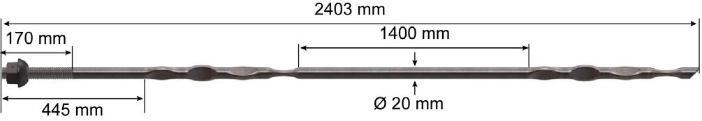

to accommodate rockbolts of up to 2.4 m in length (Knox and Hadjigeorgiou, 2023 a). This was achieved by increasing the dimensions of the load trollies and the concrete blocks through which the rockbolt is installed. The primary components of the machine are illustrated in Figure 15. The two loading trollies (shear and axial) are driven by two independently controlled hydraulic cylinders to achieve a desired displacement or load vector at the joint between the two concrete blocks. The displacement is monitored via linear variable displacement transducers located internally to the hydraulic cylinders and strategically placed on the interfaces between the components of the loading train to account for relative movements. The reactive force was generated by the test specimen in response to the applied displacement record using four load cells located at the interface between the hydraulic cylinders and the loading frame.
The preparation of the concrete blocks that followed the procedure is described in detail by Knox and Hadjigeorgiou (2023 a). After a curing period of 28 days, boreholes drilled with a Ø36 mm knock-off bit were prepared prior to the installation of the concrete blocks into the loading frame. The pre-drilled boreholes are aligned, and each sample of Ø20 mm 2.4 m rockbolt was individually installed through the two concrete blocks.

The rockbolt was subjected to one of the loading configurations illustrated in Figure 16: axial (0°) (Figure 16a), combination (30°, 60°, Figure 16b) or shear (90°, Figure 16c). The loading angle is referenced relative from the axis of the borehole as illustrated in Figure 16 d, with the constant displacement rates of the axial and shear trollies being configured to achieve a resultant displacement rate of 0.5 mm/s for all loading configurations.
Combination shear and tensile testing results
Batches of three samples of the Ø20 mm, 2.4 m PAR1 paddled energy-absorbing rockbolts were tested at each loading configuration. The load displacement responses for each loading angle are presented in Figure 17; a high degree of consistency in the response of the rockbolt is observed at each loading angle. The comparison between the ultimate load and displacement at ultimate load is presented in Figure 18. A trend of reducing load and displacement capacity is observed as the loading angle increases.
Paddled energy-absorbing rockbolt performance considerations
A paddled energy-absorbing rockbolt dissipates energy through the plastic deformation of steel. Thus, the mechanical properties of the steel, diameter of the bar and length of bar mobilized directly affect the capacity of the rockbolt. A key consideration is illustrated in the comparison between the axial loading case of the work of Chen and Li (2015) and the results presented in this paper. In the work of Chen and Li (2015), the mobilized length of steel was 1.0 m resulting in a displacement at ultimate load capacity of 116 mm (11.6 % strain). The mobilized length of steel for the work presented in this paper was 1.4 m, with a displacement at ultimate load capacity of 143 mm (10.2% strain). Consequently, the increase in mobilized length resulted in an increase in capacity. Thus, the position of the anchor points distributed along the length of the paddled energy-absorbing rockbolt (thus the potential free length of
bar) should be considered when comparing the performance. Due to the difference in mechanical properties and length of the steel between the anchor points, a relative load and relative displacement is used to compare the response of the paddled energy-absorbing rockbolt recorded by Chen and Li (2015) and the investigation presented in the paper. The relative capacity for a given loading angle is determined by normalizing the average capacity by the capacity of the rockbolt during axial (0°) loading. The relative capacity comparison between the two datasets is plotted in Figure 19.
Based on the two datasets, a trend of decreasing capacity with an increase in loading angle is observed. A minor decrease (<10%) in the load capacity is observed in the performance of the load capacity, owing to the composite loading mechanism. The shear capacity of the installed rockbolt is higher than the theoretical shear capacity of the rockbolt (50 – 60%). The failure of the chemical medium and host material at the joint, prior to the rupture of the rockbolt resulted in bending of the rockbolt allowing the bar to align with the direction of the loading. This results in a rupture, which is predominately tensile at a local scale. Both datasets recorded a change in ultimate load capacity of less than 1% at a loading angle of less than 40°. Differences were observed at 60° and 90°, with the greatest reduction (6%) in ultimate load recorded at 60° for the work presented by Chen and Li (2015). However the greatest reduction (9%) in load was recorded at a loading angle of 90°, i.e., pure shear, in this investigation.
The trend of the reduction in relative displacement observed in Figure 19 is also consistent between the two datasets, with much of the reduction (≈ 50%) in the displacement capacity resulting from the change of loading angle between axial (0°) and 40°. From 40° up to shear (90°) loading, the further reduction in displacement capacity recorded was less than 10% of the displacement capacity of the axially-loading rockbolt. Of interest is the similarity in shear (90°) displacement capacity recorded in both datasets. The length
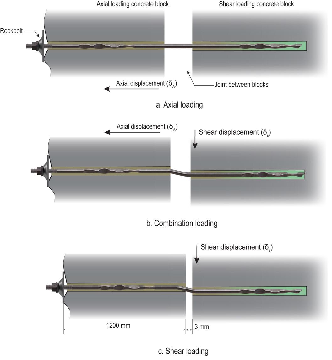
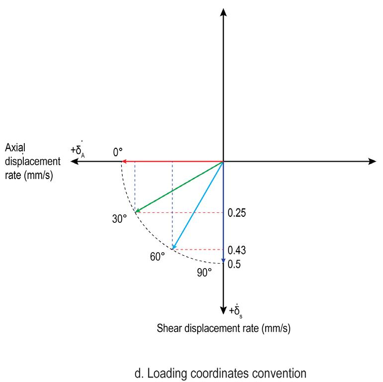

17—Combination load-displacement response for a Ø20 mm 2.4 m paddled energy-absorbing rockbolt
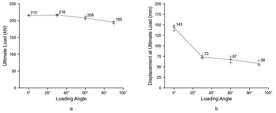
of smooth bar between the two anchor points varied 1.0 m (Chen and Li, 2015) and 1.4 m, thus resulting in a difference of 27 mm of average axial (0°) displacement capacity between the two data sets due to the increase in the mobilized length of steel. However, the difference in average shear (90°) displacement capacity recorded was 1 mm, suggesting that the shear capacity of a rockbolt is independent of the length of the rockbolt. The change in response of the paddled energy-absorbing rockbolt may be due to the induced bending, resulting from failure of the chemical anchor and host material at the shear interface, negating the debonding effect of the smooth bar from which the rockbolt is produced. Thus, if shear was to occur at multiple joints positioned sufficiently apart along a length between two anchor points, the joints would be loaded independently.
The influence of the loading configuration on the performance of a paddled energy-absorbing rockbolt was previously quantified by Knox and Hadjigeorgiou (2022). The investigation was conducted using the drop test methodology with the location of a joint intersected by the rockbolt. The purpose of the investigation of the joint was simulated by a discontinuity ‘split’ in the host tube. The two loading configurations (direct and indirect) were used in combination with the varied split location. The investigation demonstrated the following:
➤ The position of the split can affect the capacity of a paddled energy-absorbing rockbolt by up to 90%
➤ The position of the split within the length between two anchor points may affect the capacity of a paddled energy-absorbing rockbolt
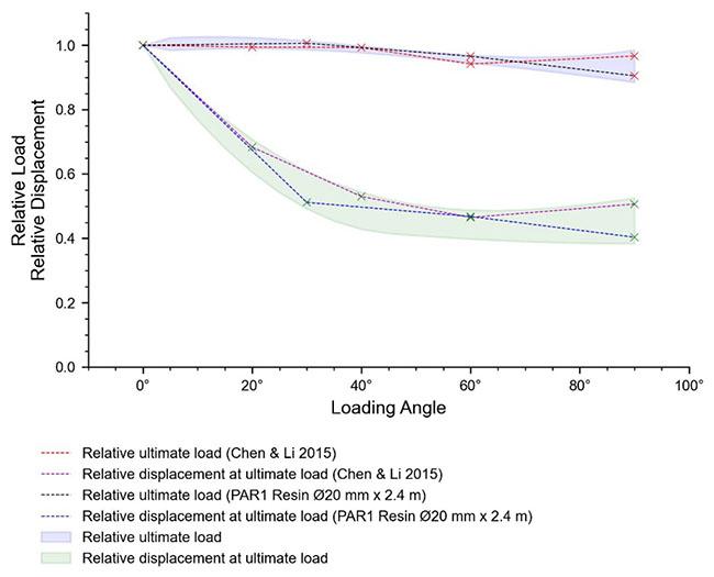

➤ The loading configuration (direct vs indirect) can affect the capacity of a paddled energy-absorbing rockbolt independent of the split location.
Based on the above observations and the data presented by Knox and Hadjigeorgiou (2022), a performance capacity envelope was developed and is illustrated in Figure 20. A linear relationship between the paddle sets was assumed.
The investigations into the effect of the loading angle on the capacity of a paddled energy-absorbing rockbolt by both Chen and Li (2015), and the investigation presented in this paper were conducted at a quasi-static loading rate, with the laboratory investigation into the influence of the testing configuration conducted through impact loading, thus at higher strain rates. Consequently, the effect of the loading rate on the result should be taken into account. It is arguable that a rockbolt will be subjected to a combination loading case during a seismic event and the possible resulting rockburst. Based on the data presented it should be taken into consideration that an anticipated combination of loading cases
at higher strain rates would result in a reduction of displacement capacity.
Conclusion
It is widely accepted within the mining industry that the implementation a of yielding rock reinforcement system is a best practice when the anticipated rock mass failure mode will result in either squeezing or rockbursting. The proliferation of the use of paddled energy-absorbing rockbolts evolved based on the results of laboratory testing and field observations. In addition, the similarities in the installation procedure between rebar rockbolts and the paddled energy-absorbing rockbolt reduced the implementation complexity, as no training or equipment modification is required to facilitate incorporation into the ground support standard of a mine site installing rebar bolts.
This paper reviewed recent investigations to further understand the behaviour of paddled energy-absorbing rockbolts under complex loading mechanisms. This is necessary to provide an
explanation of variations in field performance observations. Typically, two impact testing configurations exist: The direct impact continuous tube test and the indirect impact split tube test, with the split for the indirect impact test located centrally between two anchor points. However, both the position of the split and the configuration of the split locations have been demonstrated to have a significant effect (up to 90% variance) on the capacity of a paddled energy-absorbing rockbolt. Similarly, through two investigations conducted at quasi-static loading rates, the loading angle has been demonstrated to have a significant effect on the displacement capacity (up to 60% reduction) of a paddled energy-absorbing rockbolt when comparing the axial and shear capacity.
Due to the variances in the capacity observed through the variance of the testing configuration – loading mechanism, direction of loading, location/presence of a discontinuity – it must be concluded that the capacity of a rockbolt determined though laboratory-based testing is not independent of the testing configuration. When designing a ground support system as a geotechnical practitioner, careful consideration should be given to the applicability of a laboratory-based test with respect to the anticipated in situ loading to which the rockbolt will be subjected.
It is important to recognize that extrapolating from the laboratory conditions requires that the field installation is up to standard and that there is a good load transfer so that the rockbolt can attain its capacity. This necessitates the use of best QA/QC installation practice and compatibility between the surface support.
The authors acknowledge Epiroc for providing access to the testing facility, and the PAR1 bolts used in this testing campaign. The contribution of Lwazi Pambuka and his team in operating the testing facility is gratefully acknowledged, as is the support of the Natural Science Engineering Council of Canada.
References
Bosman, K., Cawood, M., Berghorst, A. 2018. The relationship between the magnitude of the input energy per impulse and the cumulative absorbed energy. Rock Dynamics and Applications 3: Proceedings of the 3rd International Conference on Rock Dynamics and Applications (RocDyn-3). Trondheim, Norway: CRC Press/ Balkema.
Chen, L. and Li, C. 2015. Performance of fully encapsulated rebar bolts and D-Bolts under combined pull-and-shear loading. Tunnelling and Underground Space Technology, vol. 45, pp. 99–106.
Epiroc. 2024. PAR1 Bolt. https://www.epiroc.com/en-za/products/ rock-drilling-tools/ground-support/energy-absorbingrockbolts/par1-resin-bolt [accessed: 16 February 2024]
Hadjigeorgiou, J., Potvin, Y. 2011. A Critical Assessment of Dynamic Rock Reinforcement and Support Testing Facilities. Rock Mechanics Rock Engineering, vol. 44, pp. 565–578.
Jager, A.J. 1992. Two new support units for the control of rockburst damage. Kaiser PK, McCreath DR, editors. Rock support in mining and underground construction. Rotterdam: Balkema; pp. 621–631.
Knox, G. Berghorst, A., Crompton, B. 2018. The relationship between the magnitude of impact velocity per impulse and the cumulative absorbed energy capacity of a rockbolt. Proceedings of the Fourth Australasian Ground Control in Mining Conference Proceedings, The Australasian Institute of Mining and Metallurgy, Melbourne, pp. 160–169
Knox, G., Hadjigeorgiou, J. 2022. Influence of testing configuration on the performance of paddled energy-absorbing rockbolts
under impact loading. Rock Mechanics and Rock Engineering, vol. 55, pp. 5705–5721.
Knox, G., Hadjigeorgiou, J. 2023a. Performance of conventional and energy-absorbing self-drilling hollow core rockbolts under controlled laboratory conditions. Rock Mechanics and Rock Engineering, vol. 56, pp. 4363–4378.
Knox, G., Hadjigeorgiou, J. 2023b. Performance of mechanical hybrid rockbolts. in: Wesseloo, J. (ed), Ground Support 2023: Proceedings of the 10th International Conference on Ground Support in Mining, Australian Centre for Geomechanics, Perth, pp. 495–506.
Li, C.C. 2010. A new energy-absorbing bolt for rock support in high stress rock masses. International Journal of Rock Mechanics and Mining Sciences, vol. 47, pp. 396–404.
Li, C., Doucet, C. 2012. Performance of D-Bolts Under Dynamic Loading. Rock Mechanics and Rock Engineering, vol. 45, pp. 193–204.
Li, L., Hagan, P.C., Saydam, S., Hebblewhite, B. 2016. Shear resistance contribution of support system in double shear test. Tunnelling and Underground Space Technology, vol. 56, pp. 168–175.
Li, C., Hadjigeorgiou, J., Mikula, P., Knox, G., Darlington, G., Royer, R., Pytlik, A., Hosp M. 2021. Performance of Identical Rockbolts Tested on Four Dynamic Testing Rigs Employing the Direct Impact Method. Journal of Rock Mechanics and Geotechnical Engineering. vol. 13, no. 4, pp. 745–754.
Moyo, T., Stacey, T.R. 2012. Mechanisms of rockbolt support in jointed rock masses. in: Potvin, Y. (ed.), Deeping Mining 2012: Proceedings of the Sixth International Seminar on Deep and Hight Stress Mining, Australian Centre for Geomechanics, Perth, pp. 91–104.
Ortlepp, W.D. 1969. An Empirical Determination of the Effectiveness of Rockbolt Support under Impulse Loading. Proceedings of the International Symposium on Large Permanent Underground Openings, Oslo, pp. 197–205.
Potvin, Y., Hadjigeorgiou, J., 2020. Ground Support for underground mines. Australian Centre for Geomechanics, p. 520.
Simser, B., Andrieux, P., Mercier-Langevin, F., Parrott, T., Turcotte, P. 2007. Field behaviour and failure modes of modified conebolts at the Craig, LaRonde and Brunswick mines in Canada. In: Potvin, Y., Hadjigeorgiou, J. and Stacey, T.R. (eds), Challenges in deep and high stress mining. Perth: Australian Centre for Geomechanics. pp. 347–354.
Stacey, T.R. 2012. A philosophical view on the testing of rock support for rockburst conditions. The Journal of the Southern African Institute of Mining and Metallurgy, vol. 112, pp. 703–710
Stjern, G. 1995. Practical Performance of rockbolts. PhD thesis, Norway University of Science and Technology, Trondheim
Villaescusa, E., Thompson, A.G., Player, J.R. 2015. Report No. 312 Dynamic Testing of Ground Support Systems, Minerals Research Institute of Western Australia, Perth
Windsor, C.R., Thompson, A.G. 1997. Reinforced rock system characteristics. In Broch, E., Myrvang, A., Stjern, G. (eds), International symposium on rock support: Applied solutions for underground structures, Lillehammer Norway, pp. 433-448.
Yao, M., Sampson-Forsythe, A., Punkkinen, A.R. 2014. Examples of ground support practice in challenging ground conditions at Vale’s deep operations in Sudbury. In Hudyma, M., Potvin, Y. (eds), Deep Mining 2014: Proceedings of the Seventh International Conference on Deep and High Stress Mining, Australian Centre for Geomechanics, Perth, pp. 291–304. u
MASLOW HOTEL, SANDTON, JOHANNESBURG
During closure planning there are usually four parties involved, being the mining house, external stakeholders, consultants and the authorities who are responsible for closure plan and eventual relinquishment approval. There are subsequently numerous conflicting ideals between the parties during the evolution of mine planning to post-closure. This leads to unrealistic closure expectations and vague obligations that result in the lack of setting or accepting specific closure and relinquishment criteria. Without clear direction, achieving a closure certificate in South Africa remains uncertain. This leads industry to adopt very different positions around closure planning that ranges between best practice, compliance to legislation to minimal planning.
Successful relinquishment has been achieved internationally by creating a value chain for sustainable post-mining economies as early as possible. In South Africa relinquishment could possibly be achieved successfully by complying to the current legislative closure approach or alternatively by creating third party value by means of parallel economies. This could potentially be supplemented with a regional closure approach between mining houses. It is therefore imperative that the third party needs to be part of the value chain development and execution through meaningful community engagement to ensure the benefits of local knowledge and achieve social acceptance. Once the long-term value chain is in place it lays the foundation for closure- and relinquishment criteria and social integration. ESG compliance adds another layer to closure planning but can be very useful to add specific criteria and expedite closure actions. Regardless of the approach taken, engagement with regulators is required for overall alignment and changes to policies.
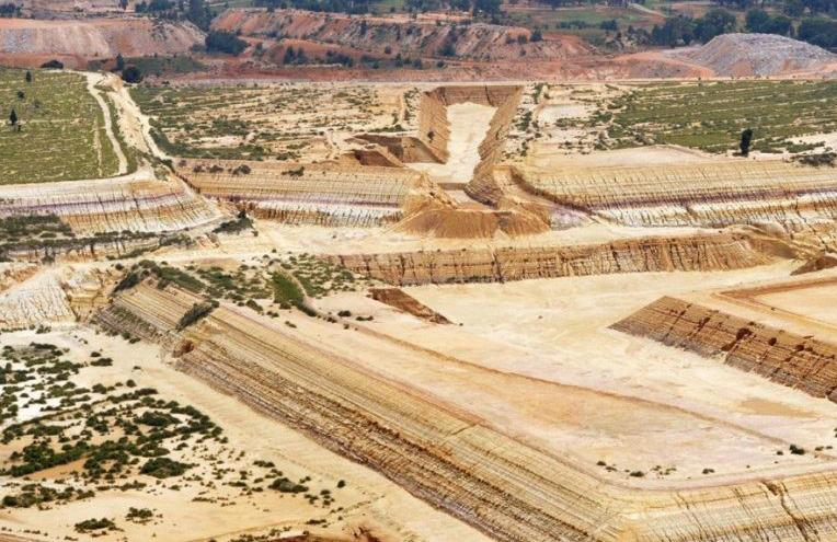
To assist interested parties, industry and regulators to better understand the closure challenges within the current uncertain and fragmented closure space. This is underpinned by Environmental Social and Governance (ESG) compliance, reducing closure liabilities and risks, just transition and the ultimate goal of relinquishment. The conference will aim to present, workshop and identify the pressing focus areas for further research and engagement with the regulators.
• Current challenges towards relinquishment
• Alternative closure solutions
• Socio economics and just transitions
• ESG compliance and considerations to closure
• Conference proceedings
• Conference panel discussion to identify focus areas, needs and future actions
• Planned breakaway after the conference for academics and after interested parties to discuss future research topics flowing from the conference
• Identify relevant challenges and research topics
• Identifying areas for future engagement with the regulator to influence policy and legislation to address the challenges
• To promote and understand the appetite of the industry to consider alternative closure solutions
Gugu Charlie, Conferences and Events Co-ordinator FOR FURTHER
Affiliation:
North West University Business School, Faculty of Economics and Management Sciences, South Africa
Email: eddykuips@hotmail.com
Dates:
Received: 1 Sept. 2023
Revised: 20 Jun. 2024
Accepted: 1 Aug. 2024
Published: September 2024
How to cite:
E. Kuipa and J.N. Lekunze.
2024. Management Gaps in the Implementation of Legislation Regulating Derelict and Ownerless Mines in South Africa. Journal of the Southern African Institute of Mining and Metallurgy, vol. 124, no. 9. pp. 547–554
DOI ID:
http://dx.doi.org/10.17159/24119717/3124/2024
ORCID:
E. Kuipa
http://orcid.org/0000-0003-0230-6743
J. Lekunze
http://orcid.org/0000-0001-7919-4908
by E. Kuipa and J.N. Lekunze
Abstract
Little attention has been paid to the rehabilitation of derelict and ownerless mines in South Africa after their lifespan. This paper aims to explore management gaps in legislation that have resulted in the non-rehabilitation of derelict and ownerless mines in South Africa. There is growing evidence that supports the distressing effects of mining on people living around these mines in the North West Province. This paper was motivated by the current socio-economic status quo of old mining towns, the influx of illegal miners (Zama Zamas), severe environmental damages, and the violence associated with derelict mines.
Underpinning this research was an ecosystem approach and integrated resources management principles, which formed the foundation for the decision-making process.The researcher used a mixed-method approach and employed convergent techniques. A semi-structured instrument was used to collect data from 200 respondents. The results indicated that there is a dire need for community-based consultative processes, and an absence of clear guidelines for derelict and ownerless mines to pressure mine management to adhere to rehabilitation standards. Moreover, the mining charter is ambiguous regarding policy implementation, budgetary allocation, and duration of the rehabilitation of these mines.
The paper concluded that management challenges associated with derelict mines can be reduced if all stakeholders follow the guidelines as outlined in the environmental legislative framework (NEMA) of South Africa while being open to innovations in line with international best practices. It also contributes towards the development of guidelines for the management and implementation of legislation related to derelict and ownerless mines in South Africa from a philosophical, theoretical, and policy perspective.
Keywords
Legislation, management, environmental, abandoned mines, South Africa
Introduction
The lack of proper management and rehabilitation of derelict and ownerless mines worldwide has resulted in socio-economic and environmental problems in areas where they exist, of which immediate attention is needed. Furthermore, the weak mining regulatory systems coupled with poor management strategies for the rehabilitation of these mines have resulted in severe social, economic, and environmental challenges. Logan, Murphy, and Beale (2007) have observed the increasing number of derelict and ownerless mines in South Africa and a concern for the environment and humans, whilst Kloppers, Horn, and Visser, (2015) have explained that mine closure forms part of a mine's long-term planning towards the creation of sustainable living outcomes through the minimization of environmental, social, and economic impacts on host communities once mining has ceased.
Regrattably, the abundance of these mines in South Africa have reached an unprecedented level, which necessitates serious consideration and immediate rehabilitation. The non-rehabilitation of mines has continued to aggravate the living conditions of the surrounding communities. This paper explores the gaps in legislation for the management and rehabilitation of derelict and ownerless mines in South Africa. The premise is that the lack of a context-based framework by the South African government pertaining to the assignment of responsibilities, the potential costs (externalities) of rehabilitation, and the absence of uniform criteria and standards for the management and rehabilitation of derelict and ownerless mines (United Nations Environment Programme, 2019), lead to an increased number of derelict and ownerless mines in South Africa.
In the absence of a context-based framework for the management and rehabilitation of mines in South Africa, the country faces an increase in acid mine drainage flow, contamination of underground water, increased gang violence among illegal miners, drug and substance abuse, murders, and theft in communities surrounding these mines. The reason for the increasing number of derelict and ownerless mines in the country may be attributed to the existing management frameworks for mines in South Africa that do not explicitly state the processes to be followed in the rehabilitation of derelict mines (Unger et al., 2020) when compared to those of the leading mining countries, such as Australia and Canada. This has been confirmed in a report by the United Nations Environment Programme (UNEP, 2019), which found that the potential costs (externalities) of rehabilitation, the lack of a context-based framework with clearly assigned responsibilities, the absence of uniform criteria and standards for rehabilitation, and other related factors delay stakeholders, governments and communities to rehabilitate mines after they have reached the end of their lifespan in South Africa.
Swart, (2019) asserts that, although the Mineral and Petroleum Resources Development Act (MPRDA) 28 of 2002, the National Environmental Management Act (NEMA) 107 of 1998, the Framework for Mine Closure of 2018, the South African Constitution of 1996 as well as the common law, Minerals Act No 50 of 1991, the National Water Act (NWA) No 36 of 1998, and the Mine Health and Safety Act No 29 of 1996 are key pieces of legislation guiding mine closure in South Africa, they still leave major gaps in addressing the challenges of derelict and ownerless mines. Nonetheless, the changing developmental patterns and mining operations in South Africa compel mine stakeholders to respond quickly and rehabilitate mines once their lifespans are reached (World Bank, 2019). The changes in developmental patterns in South Africa since 1994 at social, economic, and political levels have led to many derelict and ownerless mines being abandoned without being rehabilitated. As a result, the number of these mines in South Africa is on the rise and poses serious concerns (Watson, 2019), as the challenges of poverty, inequality, and unemployment reach unprecedented levels. Furthermore, the lack of an explicit framework for the management and rehabilitation of derelict mines poses severe challenges in the communities that are situated around these mines (Van Druten and Bekker, 2017).
Research context
There is growing evidence of the after-effects of derelict and ownerless mines in communities and this is reflected in the socioeconomic challenges of old mining towns, such as higher levels of poverty, starvation, poor housing conditions, and an increasing disease burden coupled with the influx of illegal miners searching for minerals through open shafts (Zama Zamas). Ledwaba and Mutemeri (2017) state that in South Africa, approximately 347 lives were lost between 2012 and 2016 due to the collapse of derelict mine shafts that are still being mined by illegal miners. Furthermore, the Promotion of Access to Information Amendment Bill 31 of 2019 (PAIA) reported that 787 mine closure certificates were issued across the country between 2011 and 2016. Only 17% of these closure certificates were issued to mainstream mining companies and 83% went to prospecting rights, mining permits, or borrow pits as well as other work associated with highway construction. Whether these closure permits were issued after derelict mines were rehabilitated cannot be established, as the number of such mines is on the rise. A data-driven investigation
from the Department of Mineral Resources and Energy (DMRE) shows that approximately R60 billion was budgeted for mine rehabilitation over the same period, but, to date, the funds remain unused to date. As such, the increasing number of derelict and ownerless mines in the country should raise concerns about the existing mining framework and the escalating costs for the management and rehabilitation of mines once they have reached the end of their lifespan (Brown, 2007; Nzimande and Chauke, 2012).
Mhlongo and Amponsah-Dacosta (2016), add that derelict and ownerless mines without rehabilitation escalate physical and environmental problems in their immediate communities, and according to UNESCO (2019), R60 billion (USD 29 billion) has been reserved for the rehabilitation of over 6000 derelict and ownerless mines in South Africa. However, the absence of a contextspecific management framework that specifies clear rehabilitation standards, prioritization criteria, costing, and the presence of artisanal and small-scale mining (ASM) actors have hindered effective rehabilitation efforts.
This paper aims to explore gaps in the implementation of the existing legislative frameworks for the management of these mines in South Africa by conducting a critical review of the literature on theories underpinning the existing management frameworks for the rehabilitation of derelict and ownerless mines in South Africa. Furthermore, it aims to describe the implementation strategies of the existing management frameworks for the management and rehabilitation of mines in South Africa.
Although the literature on the management and rehabilitation of derelict and ownerless mines in South Africa is limited, the existing mining charter defines derelict and ownerless sites as 'mines where mining leases or titles no longer exist; and the responsibility for rehabilitation cannot be allocated to any individual, company or organization responsible for the original mining activities' (MCMPR/MCA 2010). Furthermore, there is no official global inventory for them, but countries such as Canada, Brazil, Germany, and Australia are leading the way in the creation of an inventory (Unger et al., 2015).
In South Africa, the existing management frameworks for mines compared to those of the leading mining countries around the world do not explicitly state the processes that must be followed in the rehabilitation of derelict and ownerless mines (Unger et al., 2020). This is the case despite Sections 28 and 24 R (1) of the National Environmental Management Act 107 of 1998 (NEMA) and Section 34(a) of the Mineral and Petroleum Resources Development Act 28 of 2002 (MPRDA) stating that 'the mining right holder retains responsibility for derelict mines until the Minister of Mineral Resources (MMR) issues them with a closure certificate' (Klopper and Wessel, 2017). These sections stipulate that the mining right holder takes responsibility for environmental liability, pollution, ecological degradation, and the management thereof but not the socio-economic (externalities) liabilities posed by these mines to surrounding communities (Alberts et al., 2017). Furthermore, these legislations fail to explicitly specify the management processes for, and the timeframe within which the responsible stakeholders must rehabilitate mines after the lifespan is reached before a certificate of closure is issued.
The ever-increasing illegal activities in unsafe, derelict, and ownerless mine shafts caused by illegal miners ( Zama-Zamas), and the growing evidence that the effects of these mines on the living conditions of people in communities close to these deteriorating mines are worrisome. Before the passing into law of
the Minerals Act of 1991, many mining companies according to Swart (2003) 'used irresponsible mining methods with no regard towards protecting the environment and had often shirked their responsibility towards environmental rehabilitation by leaving an area unrehabilitated before they are being liquidated or leaving the country'.
Furthermore, the constant iterations and amendments in the current management framework for the rehabilitation of mines, the deletion of Sections 38 to 42 of the Mineral and Petroleum Resources Development Act (MPRDA) of 2002, which dealt with environmental governance, and the none-replacement of the deleted section under the National Environmental Management Act (NEMA), which resulted in a major gap in environmental legislation, are of serious concern. Moreover, the government continues to ignore this gap, and the effects on communities around disused mines are worsening.
Despite the United Nations Environment Programme (UNEP, 2019) report, that stresses the potential costs of none-rehabilitation, the lack of clearly assigned responsibilities, the absence of criteria and standards of rehabilitation, as well as other factors have delayed action by all parties. These parties are, in particular, being industry, governments, and communities in the past, given the changing developmental patterns in South Africa. The MPDRA Amendment Bill in the 2013 regulatory framework neither makes provision for cases of derelict and ownerless mines, nor does the legislation delegate due responsibility or have an approved strategic plan for their rehabilitation. An additional challenge in governing mine closure is the fact that the impact of mining cuts across the authorities of several government departments, all of whom are bound to play an important role in the management of legislation (Van Tonder et al., 2009). The shortage of relevant mine closure skills and knowledge within the regulator is a major concern as well as reason for the unsuccessful closure. This is a major gap in the management and rehabilitation of disused mines in South Africa. Moreover, the Mining Charter III is also seen as a regulatory instrument rather than a framework aimed at incorporating socio-economic challenges as an inclusion in the management and rehabilitation of derelict and ownerless mines in this framework (Moodley, 2019). The mining charter does not provide policy implementation, budgetary, and timeframe guidelines for the rehabilitation of these mines and therefore leaves serious gaps because it fails to make provision for a time-bounded deadline. This has resulted in delays in the rehabilitation programme and consequently harms the communities where derelict and ownerless mines are situated. Matshusa (2017) are of the view that existing mine owners and host communities are central in the management processes and rehabilitation of mines after the end of its lifespan is reached. Despite the limitations in the existing frameworks, there are two frameworks enacted by the South African government designed to combat the problems associated with the management of mines in South Africa, i.e., the National Environment Management Act (NEMA) and the Mineral and Petroleum Resources Development Act (MPRDA).
The National Environment Management Act (NEMA) 107 of 1998
The NEMA Act provides for cooperative environmental governance by establishing principles for decision-making on matters affecting the environment, institutions that promote cooperative governance, and procedures for coordinating environmental functions
exercised by organs of the state (NEMA, 1998). However, the NEMA Act, 2003 (Act No. 46 of 2003) only deals with compliance and enforcement and provides for Environmental Management Inspectors (EMIs). The act therefore aligns environmental requirements in the MPRDA 8 of 2002 with NEMA (1998). All NEMA amendments (2003, 2008, and 2009) concentrate on environmental conservation, rather than processes of rehabilitation and closure of the disused mines. Therefore, the framework does not specify the management framework processes for mine closure and how the effects can be mitigated in the surrounding communities where derelict and ownerless mines are located.
Several amendments have been made to the MPRDA, of which the mission was to provide equitable access to sustainable development of South Africa’s mineral and petroleum resources. According to Swart (2003), the MPRDA 2002 provides a holistic cradle-tograve approach to prospecting and mining, and fully internalizing economic, social, and environmental costs to achieve sustainable development in mineral resources. This act determines that such an application must include information about the name of the applicant applying for a closure certificate, the number of the permission, permit, or right in the region within which mine activities occur, the type of permission, permit, or the right type of mineral(s) details of land, area or offshore license block, and the reason for the application for a closure certificate.
The Mining Charter, 2018, was derived from the Mineral and Petroleum Resources Development Act of 2002 (MPRDA Act No. 28 of 2002). The charter is an important instrument in creating governance certainty, sustainable growth, and a changed mining industry. However, the charter fails to address the issue of management and rehabilitation of derelict and ownerless mines, although it provides for procedures and processes for issuing of licenses and beneficiation. The charter does not provide for policy implementation, budget, and a timeframe to work on the rehabilitation of derelict and ownerless mines.
The researcher followed a mono-method research approach, similar to that of Leedy and Ormrod (2016), who opined that research gaps associated with the development of a framework are complex. Since this paper intends to fill in the gaps in the existing legislation for the management and rehabilitation of derelict and ownerless mines in South Africa, a mono-method research approach was appropriate. The philosophical assumptions that underpin the research question and the research problem are premised on an ontological view for the collection of data in the development of a framework for the management and rehabilitation of derelict and ownerless mines. The researcher utilized existing literature as a foundation for determining constructs that are key when developing a framework for the management and rehabilitation of these mines. The research design implemented was an exploratory sequential design and participants were purposively identified and face-to-face interviews conducted. The same persons in this paper were determined by saturation plus two participants. Qualitative data from interviews were analysed and interpreted using a thematic method of analysis, and Atlas.it was used as a tool to qualitatively analyse the data.
During analysis, there was consensus among participant groups in response to gaps in the legislation for the management and rehabilitation of derelict and ownerless mines. The focus groups observed the deleterious challenges and gaps in legislation and concluded that the worsening socio-economic conditions in communities surrounding these mines pose serious threats to humans, animals, and the environment. The common themes and quotes that emerged from participants were:
When questioned about the challenges relating to derelict and ownerless mines and how they have affected the lives of community members and their business operations, Participant ENT02 replied: "In my view, the challenges that we are facing as a community include mine pollution and toxic contaminated water sources and air. People are drinking contaminated water, and this is dangerous to the residents. Acid mine drainage from these mines is changing the water quality and causing health hazards to humans, animals, and fish destroying our livelihood." Code FMS02 said: "There is a challenge of cooperation by stakeholders, government, industry, communities, and environmental groups in creating a lasting solution to manage and rehabilitate derelict and ownerless mines in South Africa."Code CNR02 said: "I think there are challenges of changes in legislation as well as an exodus of senior management from the mining ministry to other places looking for greener pastures. This is affecting the way projects of rehabilitation take place."Code BLS02 said: "There is inadequate funding and cash flow management, which is a major challenge to the management and rehabilitation of derelict and ownerless mines".
Furthermore, participants were asked to respond to the shortcomings in the legislation that have resulted in the poor management of disused mines resulting in their non-rehabilitation in South Africa. Participant CNR02 states that: "There are shortcomings that have been identified concerning the rehabilitation of existing mine closure practices in the country. These include a lack of community consultation and monitoring of post-closure activities. To be honest, communities have not been consulted to ensure their wholehearted contribution and participation in the management and rehabilitation process of abandoned mines". Code BSL02 said: "There is inadequate social impact assessment when it comes to rehabilitation of mines. More emphasis is placed on the environment than the surrounding communities. This highlighted a negation in the entire process of mine rehabilitation". Code LPS02 said: "There is a lack of information about the monitoring of social and economic conditions in connection with the community to be affected by these mines". A question was posed whether 'mine rehabilitation is inclusive of all possible domains'. The following is an extract from participants. Code BLS01 said: "I have felt strongly that there are loopholes in the way government tackles the issue of rehabilitation of mines. Community engagement in the development of mine closure, rehabilitation, and decommissioning are some of the loopholes that require immediate attention for comprehensive closure and rehabilitation".
Furthermore, questions regarding the policies and strategies that have been put in place to ensure current mining organizations do not fall into the trap of no clear processes to rehabilitate derelict and ownerless miners resulted in the following responses: Code BLS01 said: "The government drafted two important legislative frameworks (NEMA Act and MPRDA Act) that bind current miners in the environmental aspects concerned with the closure and rehabilitation. This is a great leap in the fight to minimize derelict and ownerless
mines. If properly followed with enough resources, the government will win this war". Code CNR02 said: "What I know is that the government of South Africa established the Council for Geoscience, scientific research contracted by the Department of Mineral Resources (DMR) to manage the ownerless and derelict mines database. This body should up the pace and make sure that all derelict and ownerless mines are closed and rehabilitated".
Further questions to participants concerned challenges relating to the rehabilitation of derelict and ownerless mines and possible suggestions on the way forward to ensure a sustainable solution to the problem. Direct quotes from frespondents were: Code BLS02 said: "In my view, the only way to decipher these problems is to follow the environmental legislative framework (NEMA and MPRDA) to the letter and leave space for innovativeness in line with international best practices. Failure to adhere to the environmental legislative framework will result in severe challenges looking at the way Zama-Zamas are infiltrating these mines in search of fortune". Code EMS02 asserted that: "There should be enough budgets to counter the problems head-on". Code CNR02 indicated: "I honestly feel aggrieved by these daily challenges. I think there should be teamwork by all stakeholders involved to come up with sustainable solutions rather than leaving everything in the hands of the government. It seems the burden is too much for the government and they have run out of ideas. Strategic decisions related to management and rehabilitation should come from all angles and be implemented".
Additional questions posed involved the responsible stakeholder for the costs of rehabilitation of derelict and ownerless mines in South Africa. The participants made the following verbatim statements: Code BLS02 said: "In my view, the management and rehabilitation of derelict and ownerless mines in South Africa is a complex issue given the time these mines have been in existence and lies in the hands of the government. It is the government’s prerogative to make sure that all derelict and ownerless mines are closed to perfection". Code CNR02 said: "As far as I know the government bears the financial responsibility since it is the institution that should have ensured that there are policies and regulations in place to prevent mine abandonment". Code EMS02 said: "I strongly feel that the government’s Department of Mine Environmental Management through a programme called Mineral Policy and Promotion is responsible for the management and rehabilitation of derelict and ownerless mines in South Africa". Code TCTS02 said: "There is a need for a collaborative effort from all stakeholders than to let the government go at it alone. The minerals department could use other legislative tools to pursue previous holders of mining rights who caused environmental damage under the pre-MPRDA framework".
A description to establish the management gaps in the legislation for the management and rehabilitation of disused mines was performed using a description data analysis process. Findings from the analysis are presented in Table 1.
From the analysis, the described variables include public empowerment, which after performing factor analysis on the opinions of owners about the public being empowered with the knowledge to establish or make decisions about the rehabilitation of abandoned mines being considered. The implications are that there were gaps in the existing policies and legislation. These gaps were mostly regarding issues of land and water resources that are not being protected when derelict mines are left unrehabilitated.
Regarding the effectiveness of the Environmental Management Frameworks for South Africa, factor analysis was conducted on how effective the environmental management framework outcomes have been in the broader decision-making in the context of management
Table I
Descriptive analysis of gaps in legislation for disused mine rehabilitation in South Africa
Source: Own Source
and rehabilitation of derelict and ownerless mines in South Africa. The results indicated that this framework was not effective and the reason was the increase and persistence in the number of environmental problems that are still affecting communities surrounding derelict and ownerless mines that have not been rehabilitated.
Furthermore, a rating of the threats posed by derelict and ownerless mines that have not been rehabilitated was performed. Factors included were safety, health, and environment. Results revealed the ineffectiveness of existing legislation in the management and rehabilitation of existing mines in South Africa.
The gaps in existing legislation and policy for the management and rehabilitation of disused mines were highlighted by participants, indicating confusionsurrounding policies and legislation with no clear responsibility as to who should manage and rehabilitate these mines in South Africa. This research has shown that policies and legislations relating to the management and rehabilitation of derelict and ownerless mines seldom consider the community's views or capacitate communities to make informed decisions. This was confirmed in an earlier study by Miralas et al. (2014), who found that "the none-participation of all stakeholders in the management and development of legislations regarding mine closure speaks to a broader inadequacy in strategic planning, technical capacity and a cooperative approach that need to be underpinned by sustainability principles." Although there is a need for the government to enhance forensic auditing to ensure that there is financial prudence in allocating funds for the management and rehabilitation of derelict and ownerless mines, the surge in challenges associated with derelict mines and its effects on the daily lives of community members poses severe endangerment of human safety. This paper has established that the principal failure by stakeholders to properly manage and rehabilitate mines is due to gaps in the existing frameworks.
As mentioned in the literature review, thorough investigation into the involvement of communities as mentioned in the literature review in the decision-making process relating to the management and rehabilitation of derelict and ownerless mines points to the dire need for the formation of a community-based consultative process to ensure inclusivity when developing legislation and policies for the management of disused abandoned mines in South Africa. Furthermore, the depth of information about the monitoring of social and economic conditions of communities surrounding the derelict and ownerless mines is limited. As such, monitoring of, and consultation regarding the processes that should be involved, policy development, and legislation pertaining to the management and rehabilitation of derelict mines is encouraged. Such an inclusive
process will guarantee that the rehabilitation process enhances the community’s capability to understand the processes, and ensures that the responsible stakeholders manage and rehabilitate mines before closure certificates are issued. The emphasis should be on the surrounding communities, rather than the environment as Kabir et al. (2015) argue that the monitoring of social indicators is more difficult than those relating to the physical environment.
The findings of this research have demonstrated that there are gaps in the policies and legislation developed by the government for the management and rehabilitation of derelict and ownerless mines in South Africa. This research may contribute to the current literature since, to date, there have been and are no recent studies about the management and rehabilitation of derelict and ownerless mines in South Africa. Furthermore, community engagement in the development of mine closure, rehabilitation, and decommissioning were cited as loopholes that call for immediate attention to a comprehensive framework for the management and rehabilitation of decommissioned mines. It seems clear that the current legislation and policies are highly fragmented and do not directly or comprehensively address the problem of the rehabilitation of derelict and ownerless mines across South Africa. This research has, to some extent, provided the foundation for a new comprehensive framework for the management and rehabilitation of derelict and ownerless abandoned mines, which includes a shared responsibility and cost-sharing between stakeholders. The management and rehabilitation of mines are a universal problem and not the responsibility of one entity, but the total responsibility in South Africa currently seems to be that of the government only. This paper establishes a basis for the development of a framework whereby the responsibility to reduce the negative impact of these derelict mines on the environment, specifically the management and rehabilitation thereof, is shared between communities, mining houses, and the government.
The current legislation in South Africa, which is the MPRDA Act 28 of 2002, Section 28, states that “every person who causes, has caused or may cause significant pollution or degradation of the environment must take reasonable measures to prevent such pollution or degradation from occurring, continuing or recurring, or, in so far as such harm to the environment is authorized by law or cannot reasonably be avoided or stopped, to minimize and rectify such pollution or degradation of the environment”. This extract shows the extent to which the Act fails to allocate responsibilities amongst stakeholders when it comes to the management and rehabilitation of mines. As such, the government seems to have to bear the sole financial responsibility, since the institutions (mining organizations and communities) that should have ensured that there are policies and regulations in place to prevent total neglect or mine
abandonment, cannot be located or held accountable. Although the government of South Africa has recently drafted two important pieces of legislation (NEMA and MPRDA) as policies to guide the processes in the management and rehabilitation of mines, concerns are that they are not comprehensive and focused enough to prevent the increasing number of derelict and ownerless mines in South Africa.
The gaps in the legislative framework for the management and rehabilitation of derelict and ownerless mines in South Africa need to be addressed with the urgency it deserves. This is clear from the interviews conducted and the data gathered from all stakeholders involved in this study. It is recommended that the government speeds up the process of developing a strategic plan for the implementation of policies and legislation regarding the rehabilitation of abandoned mines to minimize the risks it poses to communities and the environment at large. Policy implementation, community consultation, inadequate social impact assessment, commitment at the highest political level, lack of clearly assigned responsibilities, the absence of criteria and standards of rehabilitation for these mines, the none prioritization of rehabilitation, and omission of Sections 38-42 were cited as some of the gaps in the implementation strategies. Stakeholders should be involved throughout all the stages of mine rehabilitation because this may assist in the development of appropriate management options for the site. This paper has shed light on the lack of targeted legislation and policies by the government and responsible parties, involving the management and rehabilitation of derelict and ownerless mines, which have resulted in worsening socio-economic conditions of the surrounding communities of these mines.
This research therefore recommends that a community-based consultative process be prioritized when developing policies and legislation about the rehabilitation of derelict and ownerless mines in South Africa. Such a process would ensure that all parties contribute effectively towards the closure and rehabilitation of these mines. Furthermore, it is recommended that any new Mining Charter should provide an implementation action plan, budget, and timeframe for the management and rehabilitation of derelict and ownerless mines. Failure to institute timelines as a key pillar may delay the rehabilitation process. The omission of Sections 38-42 of the NEMA Act of 2002 should be addressed and documented for the complete closure of these mines. The government and all other identified stakeholders areencouraged to collaborate to combat the illegal takeover of ownerless mine shafts and to develop a one-stop comprehensive framework for the management and rehabilitation of derelict and ownerless mines in South Africa.
The researcher acknowledges the contribution of the North West Business School for the full funding of this project. In addition, gratitude to the environmentalists, the Auditor General, communities, mine managers, and business communities for their immense contribution by answering the research questions, which resulted in the findings of this study.
During an extensive review of the available literature, it was found that studies on policy implementation strategies for legislation that
aims to address the management and rehabilitation of derelict and ownerless mines in South Africa are lacking. This may possibly be the reason for the persistent problems currently being experienced in the country.
References
Alberts, R., Wessels, J.A., Morrison-Saunders, Α., McHenry, M.P., Sequeira, A.R., Mtegha, H. Doepel, D. 2017. Complexities with extractive industries regulation on the African continent: What has 'best practice' legislation delivered in South Africa? The Extractive Industries and Society, vol. 4, no. 2.
Brown, J. 2007. Derelict mines to cost state R100bn. Business Report, p. 22.
Department of Mineral Resources and Energy. 2009. The national strategy for the management of derelict and ownerless mines in South Africa. Government Printer, Pretoria.
Kabir, S.M.Z., Rabbi, F., Chowdhury, M.B., and Akbar, D. 2015. A review of mine closure planning and practice in Canada and Australia. World Review of Business Research, vol. 5, no. 3, pp. 140–159.
Klopper. D, Wessels. J-A. 2017. Investigation of Western Australia’s rehabilitation fund as a fiscal policy solution for South Africa abandoned mines, South Africa.
Kloppers, B.J., Horn, C.J., Visser, J.V.Z. 2015. Strategic and tactical requirements of a mining long-term plan. Journal of the Southern African Institute of Mining and Metallurgy, vol. 115, no. 6, pp. 515–521.
Logan, R.B., Murphy, D.P., Beale, C.A. 2007. Mine closure risk and decision analysis. Proceedings of the Second International Seminar on Mine Closure, Brisbane, Australia. pp. 1–2.
Leedy, P.D., Ormrod, J.E. 2016. The Usefulness of Qualitative and Quantitative Approaches and Methods in Researching ProblemSolving Ability in Science Education Curriculum, of Education and Practice, vol. 7, no. 15, pp. 91–100.
Ledwaba, P. Mutemeri, N. 2017. Preliminary study on artisanal and small-scale mining in South Africa. Report prepared for Open Society Foundation for South Africa: Centre for Sustainability in Mining and Industry, University of the Witwatersrand.
Matshusa, K. 2017. Overview of abandoned mines in South Africa, 2nd International Convention on Geosciences and Remote Sensing. Las Vegas, USA.
MCMPR & MCA. 2010. Ministerial council on mineral and petroleum resources and minerals council of Australia. Strategic Framework for Managing Abandoned Mines in the Minerals Industry. Canberra: MCMPR & MCA.
Milaras, M., Ahmed. F., McKay, T.J.M. 2014. Mine Closure in South Africa: S Survey of current professional thinking and practice, Sustainable Mine Closure, DOI:10.13140/RG.2.1.3599.3765, South Africa.
Mhlongo, S.E., Amponsah-Dacosta, F. 2016. A review of problems and solutions of abandoned mines in South Africa. International Journal of Mining, Reclamation, and Environment, vol. 30, no. 4. pp. 279–294.
Moodley, N. 2019. SA Mining Magazine, July/August Issue, South Africa UNEP (United Nations Environment Programme). Mining and Sustainable Development II - Challenges and
Perspectives, Division of Technology, Industry, and Economics, Geneva.UNSD. (2018a). Open SDG data hub. Retrieved from, ttps://unstatsundesa.opendata.arcgis.com
Mineral and Petroleum Resources Development Act. 'Republic of South Africa. 2002.' Act No. 28 of 2002.
National Environmental Management Act. 1998. www.gov.za
Nzimande, Z., Chauke, H. 2012. Sustainable through responsible environmental mining. Journal of the Southern African Institute of Mining and Metallurgy, vol. 112, no. 2, pp. 135–139.
Swart, E. 2003. The South African legislative framework for mine closure. Proceedings of the colloquium on mine closure for Sustainable development. Journal of the Southern African Institute of Mining and Metallurgy, vol 103. no. 8, pp. 489–492.
Unger, C.J., Lechner, A.M., Kenway, J., Glenn, V., Walton, A. 2015. A jurisdictional maturity model for risk management, accountability and continual improvement of abandoned mine remediation programs. Resources Policy, 43
Unger, C.J., Lechner, A.M., Kenway, J., Glenn, V., Walton, A. 2020. A jurisdictional maturity model for risk management,
accountability, and continual improvement of abandoned mine remediation programs. Resources Policy, 43.
Van Tonder, D.M., Coetzee, H., Esterhuyse, S., Msezane, N., Strachan, L., Wade, P., Mafanya, T., Mudau, S. 2009. South Africa’s challenges about mine closure – the concept of regional mine closure strategy. Proceedings of the Third International Seminar on Mine Closure, Mine Closure (2009), A.B. Fourie, M. Tibbett, I.M., Weiersbye, P. Dye (eds), pp. 14–17.
Van Druten, E.S., Bekker, M.C. 2017. Towards an inclusive model to address unsuccessful mine closures in South Africa. Journal of the Southern African Institute of Mining and Metallurgy, vol. 117, no. 5, pp.485–490.
UNEP (United Nations Environment Programme). 2019. Mining and Sustainable Development II - Challenges and Perspectives, Division of Technology, Industry, and Economics, Geneva.
Watson, K. 2019. The Art of Medicine: Abortion as a Moral Good The Lancet, 393, pp. 1196–1197.
World Bank. 2019. The World Bank Annual Report 2019: Ending Poverty, Investing in Opportunity. Washington, DC. u
26 MAY 2025 - WORKSHOP
Sulfuric Acid Catalysis - Key Parameters to Increase Efficiency and Lower Costs
27-28 MAY 2025 - CONFERENCE
29 MAY 2025 - TECHNICAL VISIT
PROTEA HOTEL STELLENBOSCH AND CONFERENCE CENTRE, STELLENBOSCH OBJECTIVES
•
• To expose delegates to issues relating to the generation and handling of sulphur, sulphuric acid, and SO2 abatement in the metallurgical and other industries
•
• Provide an opportunity to producers and consumers of sulphur and sulphuric acid and related products to be introduced to new technologies and equipment in the field
•
• Enable participants to share information about and experience in the application of such technologies
•
• Provide an opportunity for role players in the industry to discuss common problems and their solutions.
EXHIBITION AND SPONSORSHIP
There are a number of sponsorship opportunities available. Companies wishing to sponsor or exhibit should contact the Conferences and Events Co- Ordinator.
ECSA Validated CPD Activity, Credits = 0.1 points per hour attended
FOR FURTHER INFORMATION, CONTACT: Gugu Charlie, Conferences and Events Co-Ordinator, E-mail: gugu@saimm.co.za
Pathway to industrialisation
ECSA VALIDATED CPD ACTIVITY, CREDITS = 0.1 POINTS PER HOUR ATTENDED
The primary purpose of the 2ND Hydrogen and Fuel Cells conference is the advancement of green hydrogen technologies in Southern Africa and the global community, by highlighting the power of renewable and sustainable technologies and addressing the emerging challenges—through the exploration of hydrogen production, storage and utilization using fuel cells by way of engagement with industry, academia and government. The conference will provide a platform for high level exchange and networking opportunities with various experts in the field.
Hydrogen: Production and storage
Fuel cell: Technologies, applications, and integration
Hydrogen mobility - strategies, safety, roadmaps, transitioning to hydrogen refueling stations (HRS)
Technology status in industry.
The two-day conference will feature high-level scientific talks and posters, complemented with keynote and plenary presentations on country overviews, status of leading and major players in the Southern African and global arena.
Will include inspiring technical talks, poster section as well as social networking events
Participants will have the opportunity to directly engage with conference attendees to discuss their research
FOR
The conference presents an attractive programme for researchers, industry players, academic institutions, government, investors, policy makers and potential users of fuel cell and hydrogen technologies. The focus is on building collective know-how and fostering engagement between business, government, science and academic institutions. Participants from all countries are invited and welcome to attend the event.
Gugu Charlie, Conferences and Events Co-ordinator
following deadline dates.
• Submission of abstracts deadline 31 October 2024
• Submission of papers deadline: 28 November 2024.
The conference is organized by the Southern African Institute of Mining and Metallurgy, and individuals are invited to submit papers or presentations or posters for the Conference. Titles and short abstracts (no more than 500 words) on any relevant subject should be submitted in English to:
Head of Conferences and Events
Camielah Jardine
Enquiries may be made at: Tel: +27 011 538-0237
E-mail: camielah@saimm.co.za website: www.saimm.co.za

16-17 October 2024 — ESGS Conference 2024
ESG in the minerals industry challenges and opportunities
Glenburn Lodge and Spa, Muldersdrift
Contact: Camielah Jardine
Tel: 011 538-0237, E-mail: camielah@saimm.co.za
Website: http://www.saimm.co.za
16-17 October 2024 — MESA Africa 2024 Summit
The Edge at Knightsbridge, Bryanston, Johannesburg, South Africa, Website: https://evt.to/asiuosimw
29 October 2024 — 20TH Annual Student Colloquium 2024
Mintek, Randburg, Johannesburg
Contact: Gugu Charlie
Tel: 011 538-0238, E-mail: gugu@saimm.co.za
Website: http://www.saimm.co.za
29-31 October 2024 — International Mining and Resources Conference Expo
Sydney
Website: https://imarcglobal.com/
31 October - 1 November 2024 — SANCOT Symposium 2024
Cullinan Diamond Lodge, Cullinan, Pretoria
Advances in Tunnelling-A Portal to the Future
Contact: Gugu Charlie
Tel: 011 538-0238, E-mail: gugu@saimm.co.za
Website: http://www.saimm.co.za
6-8 November 2024 — MineSafe Conference 2024
Emperors Palace Convention Centre, South Africa
Contact: Camielah Jardine
Tel: 011 538-0237, E-mail: camielah@saimm.co.za
Website: http://www.saimm.co.za
11-12 November 2024 — Mintek@90 Conference 2024
Sandton Convention Centre, South Africa
Contact: Camielah Jardine
Tel: 011 538-0237, E-mail: camielah@saimm.co.za
Website: http://www.saimm.co.za
21-23 January 2025 — 14TH South African Conference on Computational and Applied Mechanics
Wits Science Stadium, South Africa
Website: https://sacam.co.za/
19-20 February 2025 — Mine Closure Conference 2025
Maslow Hotel, Sandton, South Africa
Contact: Gugu Charlie
Tel: 011 538-0238, E-mail: gugu@saimm.co.za
Website: http://www.saimm.co.za
7-8 April 2025 — 2ND Southern African Hydrogen and Fuel Cell Conference 2025
CSIR International Convention Centre, Pretoria
Contact: Camielah Jardine
Tel: 011 538-0237, E-mail: camielah@saimm.co.za
Website: http://www.saimm.co.za
26-29 May 2025 — 9TH Sulphur and Sulphuric Acid Conference 2025
Protea Hotel Stellenbosch and Conference Centre, Stellenbosch
Contact: Gugu Charlie
Tel: 011 538-0238, E-mail: gugu@saimm.co.za
Website: http://www.saimm.co.za
25-26 June 2025 — 4TH Digital Transformation in Mining Conference 2025
Glenburn Lodge and Spa, Muldersdrift
Contact: Camielah Jardine
Tel: 011 538-0237, E-mail: camielah@saimm.co.za
Website: http://www.saimm.co.za
21-25 July 2025 — AfriRock Conference 2025
Sun City, South Africa
Contact: Camielah Jardine
Tel: 011 538-0237, E-mail: camielah@saimm.co.za
Website: http://www.saimm.co.za
16-22 November 2025 — The 12TH International Copper Conference (Copper 2025)
Phoenix, Arizona, USA
Website: https://www.extractionmeeting.org/ Extraction2025/Extraction2025/Copper2025/default.aspx
The following organizations have been admitted to the Institute as Company Affiliates
A and B Global Mining (Pty) Ltd
acQuire Technology Solutions
AECI Mining Chemicals, a division of AECI Mining Ltd
African Pegmatite
Allied Furnace Consultants
AMIRA International Africa (Pty) Ltd
Anglogold Ashanti Ltd
Anton Paar Southern Africa
Arcus Gibb (Pty) Ltd
Becker Mining (Pty) Ltd
Bluhm Burton Engineering Pty Ltd
Caledonia Mining South Africa
Castle Lead Works
DDP Specialty Products South Africa (Pty) Ltd
De-Tect Unit Inspection (Pty) Ltd
Digby Wells and Associates
EHL Consulting Engineers (Pty) Ltd
Elbroc Mining Products (Pty) Ltd
Epiroc South Africa (Pty) Ltd
Ex Mente Technologies (Pty) Ltd
Exxaro Resources Limited
FLSmidth Minerals (Pty) Ltd
G H H Mining Machines (Pty) Ltd
Geobrugg Southern Africa (Pty) Ltd
Glencore
Gravitas Minerals (Pty) Ltd
Hatch (Pty) Ltd
Herrenknecht AG
Impala Platinum Holdings Limited
IMS Engineering (Pty) Ltd
Ingwenya Mineral Processing
Ivanhoe Mines SA
Longyear South Africa (Pty) Ltd
Malvern Panalytical (Pty) Ltd
Maptek (Pty) Ltd
Mech-Industries
Micromine Africa (Pty) Ltd
Minearc South Africa (Pty) Ltd
Minerals Council of South Africa
MineRP Holding (Pty) Ltd
Mining Projection Concepts (Pty) Ltd
Mintek
MLB Investments CC
Modular Mining Systems Africa (Pty) Ltd
Murray & Roberts Cementation (Pty) Ltd
OPTRON
Paterson & Cooke Consulting Engineers (Pty) Ltd
Redpath Mining (South Africa) (Pty) Ltd
Rosond (Pty) Ltd
Roytec Global (Pty) Ltd
Rustenburg Platinum Mines Limited - Union
Salene Mining (Pty) Ltd
Schauenburg (Pty) Ltd
SENET (Pty) Ltd
Sibanye Gold Limited
Sound Mining Solution (Pty) Ltd
SRK Consulting SA (Pty) Ltd
Tomra (Pty) Ltd
Trans-Caledon Tunnel Authority
Ukwazi Mining Solutions (Pty) Ltd
VBKOM Consulting Engineers
Weir Minerals Africa
ZUTARI (Pty) Ltd
Barbara Spence · Avenue Advertising
PO Box 71308, Bryanston, 2021
Tel: 011 463 7940 X Cell: 082 881 3454
E-mail: barbara@avenue.co.za X Website: http://www.avenue.co.za

Distribution information ABC Accredited
Advert Size Casual Bookings• 2–5 Bookings• 6–12 Bookings•
• Outside front cover package (OFC/IFC/FP)
Outside front cover
Inside front cover
R39 718 R38 210Full page content page Website banner
5 minutes video / slide presentation at SAIMM conference of choice.
Inside back cover R34 396 R33 145 R31 892
Outside back cover R27 536
Double page spread* R37 518
Full page R20 637
590 R25 642
899 R36 270
011 R19 387
Half page R16 338 R15 712 R15 083
Third page R12 896 R12 268 R11 649
Quarter page horizontal R12 038 R11 412 R10 787
Special colours, positions and contracts will be priced on application
Material should be supplied in a press-optimised PDF format—colours converted to CMYK. Material should be made up in Bureau software (e.g. Quark, InDesign, Freehand, Illustrator) before converting to PDF. Screen ruling 133 mm. Although distributed digitally, the SAIMM Journal is still produced to high-resolution, print quality specifications. NOTE: Material made up in MS Word and PowerPoint is not acceptable.


Venue: Sun City, Rustenburg, South Africa
21-23 JULY 2025 – Conference
24-25 JULY 2025 – Technical Visits

Afrirock 2025 is an international Rock Mechanics Conference set to take place at Sun City, South Africa. As mining has long been a cornerstone of African economies, Rock Engineering design plays a crucial role in advancing mining operations across the continent. The conference will spotlight cutting-edge technologies such as modern geotechnical data collection techniques, 3D visualization software for geotechnical analysis, computer modelling, mechanization, and more. After the formal sessions, technical visits will be organized to provide attendees the opportunity to gain first hand practical knowledge of South African mines.
Nestled in the rolling hills of the Pilanesberg, one of South Africa’s most scenic locations, Sun City is a world unto itself and has earned its reputation as Africa’s Kingdom of Pleasure. You will find whatever you want at Sun City, from sizzling entertainment, world class casinos and restaurants to cater for all tastes, to the more relaxed poolside venue, quiet places, lush gardens, and extensive sporting facilities including two world-class golf courses. These are just some of the elements that make Sun City unique among the world’s entertainment resorts. Finally re-discovered and now part of Sun City, the Lost City and the Valley of Waves, fabled to be the Ruins of a glorious ancient civilisation, celebrate and bring to life the legends of this mystical city. The Lost City is internationally applauded for its wonderfully imaginative theme and exquisite landscaping whilst the fantastic Valley of Waves is one of the world’s most exciting waterparks.