

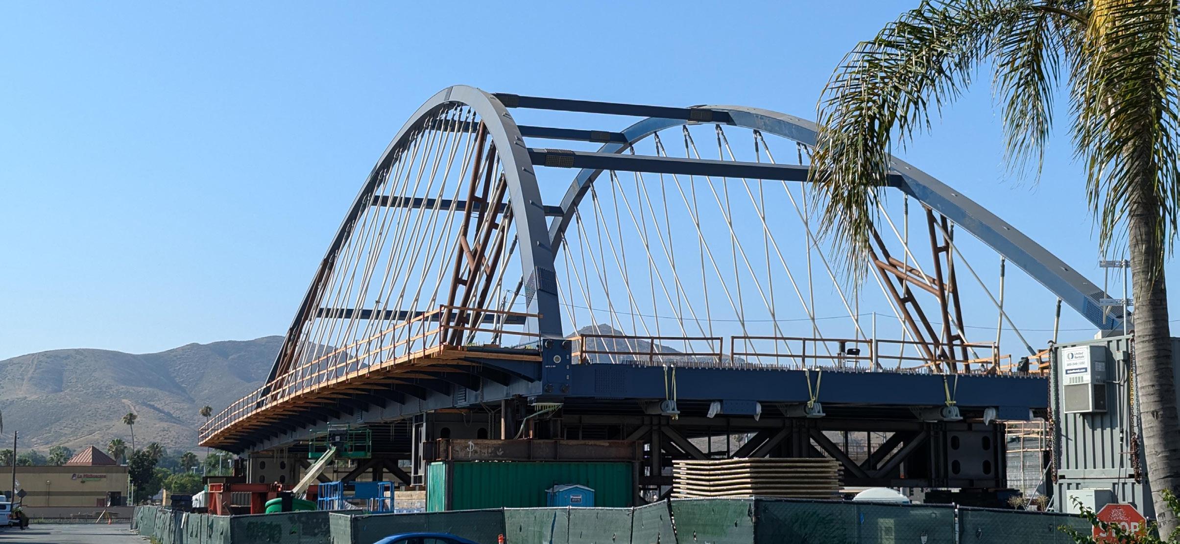
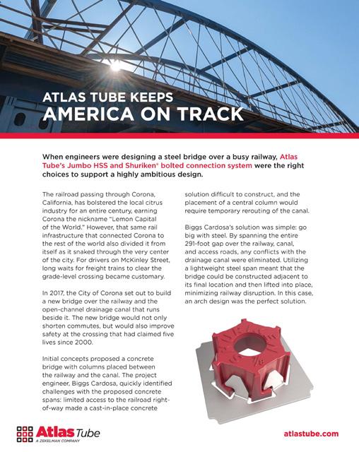
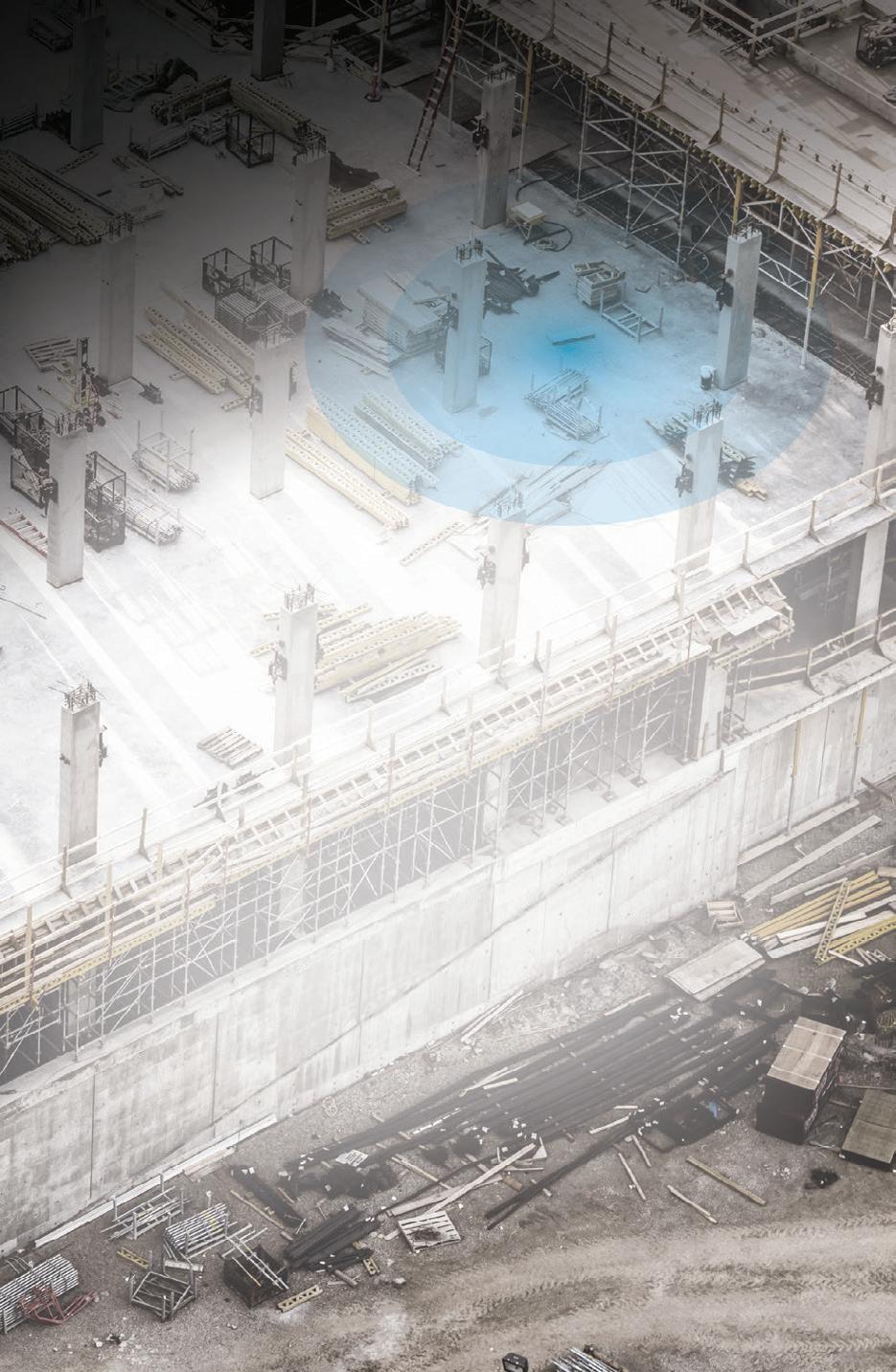
The railroad passing through Corona, California, has bolstered the local citrus industry for an entire century, earning Corona the nickname “Lemon Capital of the World.” However, that same rail infrastructure that connected Corona to the rest of the world also divided it from itself as it snaked through the very center of the city. For drivers on McKinley Street, long waits for freight and passenger trains to clear the gradelevel crossing became customary. In 2018, the City of Corona began the environmental and final design phases to build a new bridge over the railway and the open-channel drainage canal that runs beside it.
The project engineer, Biggs Cardosa, decided to go big with American steel. By spanning the entire 291-foot gap over the railway, canal, and access roads, any conflicts with the drainage
canal were eliminated. Utilizing a lightweight steel span meant that the bridge could be constructed adjacent to its final location and then lifted into place, minimizing railway disruption. In this case, an arch design was the perfect solution. Using interlaced “network” suspenders to support the deck reduced moments imposed on the arch ribs when compared to vertical suspenders, allowing the arch ribs to be lighter, more slender, and more aesthetically pleasing.
Initial designs included wide-flange X-bracing between the arch ribs, but those members were switched to parallel 22x22x7/8” Jumbo HSS members from Atlas Tube due to their ease of constructability and cleaner aesthetics. Atlas Tube’s 100% domestic Jumbo HSS helped engineers avoid the obstacles presented by wideflange beams, and its near-immediate availability provided the benefits of closed sections without fabricating additional built-up boxes for the structure.
Thompson Metal Fab (TMF), with 85 years of history in oil and gas, marine structures, and transportation, fabricated the geometrically complex structure. Walsh Construction, the largest bridge builder in the country, would self-perform the steel erection. TMF’s expertise was critical as the project included several heavy weldments with complex geometry, especially at the joint where the arch rib connects to the tie girder. According to TMF, Atlas Tube’s Jumbo HSS made a difficult job simpler.
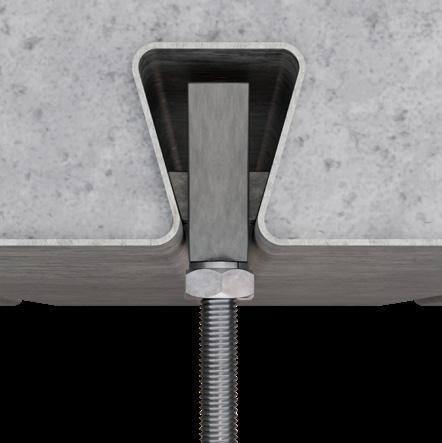
Atlas’ domestic Jumbo HSS was not the only innovation that made the bridge a reality. While the tie girders were large enough to allow ironworkers to reach the interior of the bolted splices, the arch ribs, tie beams, and support diaphragms were not. A new technology, Shuriken® by Atlas Tube, was a logical answer to this challenge.
Shuriken allows the installation of A325 and A490 bolts from one side and was the perfect solution to the connection conundrum confronting the team. By mounting the nuts on the interior of the HSS and box members, splices could be bolted up from the exterior. The built-in lateral flexibility of Shuriken preserved erection tolerance, while DuraSquirt® DTI washers from Applied Bolting Technologies made accurate tensioning and inspection easy for the slip-critical A490 bolts.
All these innovations came together to give Corona a beautiful, efficient new bridge as well as a safer and betterconnected community.
atlastube.com

Scan the QR code to read the full case study. To learn more about Atlas or to discuss your design ambitions, call 800.733.5683 or visit atlastube.com
New construction architecture requires special consideration for the inevitability of future upgrades. That’s why modern construction projects need hanging solutions that are built for speed, versatility, and adaptability to ensure quick and seamless renovations.
To help meet that challenge, Vulcraft-Verco has developed the PinTail® Anchor, an innovative hanging solution that works exclusively with our Next Generation Dovetail Floor Deck, and are specifically designed to futureproof today’s construction projects for tomorrow’s renovations.


subscriptions@structuremag.org
Chair John A. Dal Pino, S.E. Claremont Engineers Inc., Oakland, CA chair@STRUCTUREmag.org
Kevin Adamson, PE Structural Focus, Gardena, CA
Marshall Carman, PE, SE Schaefer, Cincinnati, Ohio
Erin Conaway, PE AISC, Littleton, CO
Sarah Evans, PE Walter P Moore, Houston, TX
Linda M. Kaplan, PE Pennoni, Pittsburgh, PA
Nicholas Lang, PE Vice President Engineering & Advocacy, Masonry Concrete Masonry and Hardscapes Association (CMHA)
Jessica Mandrick, PE, SE, LEED AP Gilsanz Murray Steficek, LLP, New York, NY
Brian W. Miller Cast Connex Corporation, Davis, CA
Evans Mountzouris, PE Retired, Milford, CT
Kenneth Ogorzalek, PE, SE KPFF Consulting Engineers, San Francisco, CA (WI)
John “Buddy” Showalter, PE International Code Council, Washington, DC
Eytan Solomon, PE, LEED AP Silman, New York, NY
Executive Editor Alfred Spada aspada@ncsea.com
Managing Editor Shannon Wetzel swetzel@structuremag.org
Production production@structuremag.org
Director for Sales, Marketing & Business Development
Monica Shripka Tel: 773-974-6561 monica.shripka@STRUCTUREmag.org STRUCTURE


• Concrete Repair Mortars
• Corrosion Protection
• Construction Grouts
• Waterproofing
• Sealants and Joint Fillers
• Coatings and Sealers
• Epoxy Adhesives
• Cementitious Flooring Systems
• Cure and Seals
• Densifiers
• Structural Strengthening Products
• Precast
• Epoxy Adhesives

Visit www.mapei.com/us for details on all MAPEI products. Your single-source
MAPEI offers a full range of products for concrete restoration, waterproofing and structural strengthening. Globally, MAPEI’s system solutions have been utilized for such structures as bridges, dams, tunnels, highways, parking garages, stadiums and high-rises.


By Nik Blanchette, SE; Steve Heyne, SE; and Chris Warner, SE
The comprehensive rehabilitation of a Silicon Valley high school used a composite solution.

A landslide incident on a gentle slope serves as a reminder of the importance of site investigation, desk study, and checking of overall global stability.
By Matthew Fadden, Ph.D, PE; Sedona Iodice; and Gary Klein, PE, SE
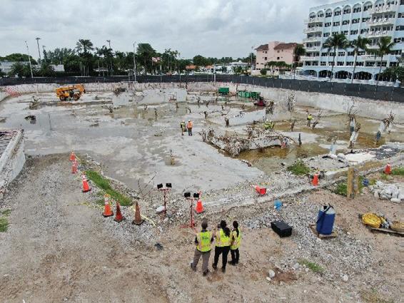
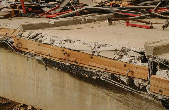
The collapse of the condo in Surfside, Florida, underscores important lessons for the structural engineering community.


floor joist systems with flush-frame connections.

Way better, weigh

Simple to specify and design, steel floor joists with flush-frame connections provide performance equal to wide-flange beams—using up to 35% less steel. Lower material and installation costs while gaining impressive advantages.


By Brian Petruzzi
The concept of borrowed belief is not new, and is certainly not mine. In fact, a quick Google search brings up other articles and entire websites dedicated to borrowed belief. I first heard the term earlier this year at a physical security design conference in Dublin, Ireland. We are all familiar with presentations at conferences dedicated to softer topics —leadership, communication, and the alike. It was a particularly busy week for me, and I was looking forward to catching up on some e-mails during a presentation titled, “The Power of Borrowed Belief” by a retail coaching consultant named Louise Lally. I’m glad I didn’t.
The concept of borrowed belief is not complex—it’s quite simple. At its core, borrowed belief is about believing in someone else before they can believe in themselves. It’s often used when someone is lacking self-confidence and needs to draw strength from the positive opinions of others to move forward in a situation. It’s about actively incorporating the trust and faith others place in you to propel your own actions and decisions.
as well as planning our local awards gala. I joined the National Council of Structural Engineers Association’s (NCSEA) Young Member Group Support Committee (YMSC) in 2016 and chaired the committee in 2018. However, my engagement with SEA-MW and NCSEA came to an abrupt halt in 2019 when I made the difficult decision to pursue a career in physical security. I still saw value in SEA-MW and NCSEA, it’s just that I thought my contributions to these organizations wouldn’t be valued once I left the profession. I had a perception of the type of person who provided value, and I no longer fit the mold.
While some may be capable of offering more, we should always be able to articulate one person we are supporting and empowering—our communities will be better for it.
Borrowed belief lays the foundation for why mentorship is so impactful to young engineers or why advocacy is a critical aspect of career development. In ways, mentorship and advocacy are forms of borrowed belief, however the concept of borrowed belief is much simpler. Winston Churchill once said that “All great things are simple.” This is why the concept of borrowed belief continues to stick with me, as the simplicity and efficacy of believing in others is borrowed belief’s greatest superpower. Let me explain. Just over six years ago I decided to leave the structural engineering profession. At the time, I was a licensed Professional Engineer with nine years of experience. I was very active in the Structural Engineers Association of Metropolitan Washington (SEA-MW), helping start our local Young Member Group in 2013 and our local career fair titled The Next Step Event in 2014,
Six months later I received a phone call informing me that I was nominated for a position on the NCSEA Board of Directors. While I didn’t see it at the time, others saw value in having a 33-year-old, with nine years of structural engineering experience, who recently transitioned out of the profession, join a board whose mission is to advance the practice of structural engineering. To be honest, it still doesn’t seem plausible after reading the above sentence today. Some would call this imposter syndrome, and they are probably right. However, the power of borrowed belief is that it doesn’t matter what the diagnosis is called. Lending support and believing in others is the simple answer. Imposter syndrome, glass ceilings, inclusion & belonging—the answer starts with believing in others.
This is where I challenge each of you. Take a moment and consider the following—who are you lending belief to right now? Maybe it’s a child who doesn’t think they are good enough to make a sports team, a colleague who is struggling to keep up with rapid advancements in technology, or a parent who is resisting elderly care. No matter your age, borrowed belief is effective in both personal and professional settings to create supportive and inclusive environments. While some may be capable of offering more, we should always
be able to articulate one person we are supporting and empowering—our communities will be better for it.
For the first time in NCSEA’s his tory, both the President and Vice President of NCSEA are Professional Engineers currently supporting other pro fessions and industries. While I’m not proposing to stage a mutiny, I do believe that diversity in thought strengthens communities. NCSEA is entering its 32nd year and has never supported a stronger community of structural engineering professionals. Our diverse programming this year includes awarding student scholarships for the NCSEA Summit in New York, issuing grants to our Artificial Intelligence (AI) Team to develop an AI roadmap for the structural engineering profession, and recently hosting our first annual Executive Leadership Retreat in Napa, California. I’m grateful for the immense belief others allowed me to borrow six years ago to continue my journey with NCSEA, and encourage all of us to empower others to join their local structural engineering association or to directly join one of NCSEA’s many committees. It’s only when we find a place for everyone that this profession will reach its maximum potential. ■

Scan the QR code to watch Louise Lally’s Tedx talk titled, “The Power of Borrowed Belief” to learn more.

Robert K. Otani, PE LEED AP, is Chief Technology Officer at Thornton Tomasetti, Inc., a 1,800+ person multidisciplinary engineering and consulting firm, and founded the CORE studio, an applications development, advanced computational modeling, and R&D group at his firm. Otani serves on the Advisory Committee for Thornton Tomasetti’s firm-wide Research and Development program. He has extensive structural design and project management experience involving commercial, infrastructure, institutional, cultural, and residential structures. Over his 29-year career, he has worked on a wide variety of complex projects, including high rise buildings, long-span roof structures, sports arenas, airport terminals, major building structural renovations, and complex art projects totaling over $3 billion USD of construction. He served as President of the Structural Engineers Association of New York in 2007 and was a professor at Pratt Institute School of Architecture from 2008-2018 and Columbia GSAPP from 2009-2015.
STRUCTURE: What inspired you to become a structural engineer?
Otani: At first, I didn’t know that I wanted to be a structural engineer. In high school I did well in math and science, I worked as a carpenter during the summers thanks to my brother, and my dad was a chemical engineer, so the combination of those factors led me to civil engineering at Rutgers University.
STRUCTURE: What were some of your most fulfilling moments during your career?
Otani: I’ve worked on some iconic and very challenging buildings, so anytime one of those projects gets built successfully—as engineered and as planned—it’s very fulfilling. From a management perspective, it has been the growth and success of the CORE studio team which I helped to create in 2010 and is now over 40 people. From a mentoring standpoint, I’ve supervised many upand-coming engineers and to see them develop into very successful project managers and leaders in the firm has been fulfilling as well.
STRUCTURE: What were the biggest challenges you experienced during the various stages of your career?
Otani: Early in my career, the biggest challenge was that despite excelling in the technical aspect of engineering, I was not recognized in the firm. So, I had to learn the business aspects of the firm. From a personal perspective, I had to learn to be more extroverted and confident in speaking. To a large extent it was self-marketing. In many ways, SEAoNY helped me with that aspect when I became very active in the organization, serving on the Board and being active in the Codes, Publications, and Programs committees.
STRUCTURE: These sound like issues that many engineers face. What would be your advice to them?
Otani: My advice would be to learn as much as possible from subject matter experts early in one’s career to excel at project technical work, be observant and learn from the successful Principals

in the firm to understand what it takes to be a leader, and raise your hand for specific initiatives within the firm that will both add value and earn recognition. Finally, it is critical that every engineer knows their strengths and weaknesses and to improve their skills when needed, which is something that is important throughout an engineer’s career. We all can improve.
STRUCTURE: Our industry has advanced significantly over the past few years with the aid of technology and now the consideration of AI. What will the impact be on our industry?
Otani: The industry has evolved tremendously over my career from mainly doing our work by hand calculations, engineering design aides, and hand drafting. I did not have a computer when I started at Thornton Tomasetti in 1995! We had shared computers when I started and only a handful of engineering software to use as compared to now, where a myriad of software are available to use. In many ways this has made it more difficult for young engineers to navigate the design of a building. What we do in terms of production has changed as well with the advent of BIM, which has led to clients asking for more detail at all stages of the design process. So technological advances have been a double-edged sword in many ways. Technology has allowed us to do more, but clients and the resulting standard of care have required us to do more, as well.
STRUCTURE: What advice would you give to someone who doesn’t know where to start with integrating AI into their daily work?
Otani: With any new technology or software, the most important aspect to know is what is its capabilities—what it does well and what it doesn’t. I explain AI as “embedded intelligence” since the data/information that AI is built upon (if done correctly) is real data and smart data and the artificial part is how the AI models are trained. So, the biggest aspect of trust in AI is going to be where and how that data was created or developed and how accurate the AI model is. That level of accuracy will determine how much an
engineer can trust AI and consequently how much double checking of that information is required.
STRUCTURE: Is there anything you miss from a time without the advanced systems we have today?
With any job there will be challenges, but if you enjoy your work and related contributions to the built environment and ultimately the cities we live in, have fun solving complex challenges along the way, and remember to find fun away from engineering and the office, then that is key to work life balance.
Otani: Absolutely. In the “old” days we used to only do analysis for a subset of a building i.e. a few columns, a few bays, and a few options for lateral systems, and use our engineering skills to make judgements about the entire building system. Now many engineers model the entire building in finite element software and let the software do the work without necessarily understanding the nuances of the behavior of the building, load paths, and sensitivity of the system layouts to the overall design. I’m hoping that AI can help engineers become better engineers as opposed to technicians using software.
STRUCTURE: What might young engineers do today in response to the difficulty of navigating so many software options available?
Otani: I think it’s the engineering firms’ responsibility to both educate young engineers on “best practices” of what software to use (as well as teach engineers how to best use the software) and when during the project timeline to use the software. However, it is also the responsibility of the young engineer to know when to ask questions to the subject matter experts in the firm and engineering organization members (like SEAoNY). My most valuable engineering lessons, both technically and professionally, came from my colleagues both at my firm and from my SEAoNY colleagues.
STRUCTURE: Sounds like mentorship is still critically important. Would you like to mention a few of yours and how they helped you?
Otani: There have been so many so I’ll only mention my first mentor, I. Paul Lew, PE, RA, who was Project Manager/Senior VP of the JFK Terminal One project that I started on. As a licensed architect and engineer, Paul had a unique combination of skills as a prolific technical engineer, but he also had an aesthetic mindset where he would seamlessly communicate with the design architects. He would perform step-by-step calculations on a yellow pad in front of the engineering team to simplify an otherwise very complex problem which was invaluable to me by instilling that every engineering problem can be broken down into simpler components if you understand load path and physics. Finally, he was the only person in the office that would detail connections in 3D autocad, which in 1995 was unheard of. That level of detailed thinking, simulation, visualization and ability to share that knowledge certainly stuck with me and has become a model for me.
STRUCTURE: As a past president of SEAoNY, what accomplishments are you proud to see in the organization now, and what do you hope for the future of SEAoNY?
Otani: I’m particularly proud that when I was President, we hired a management company (Jaffe) to help manage the SEAoNY functions and to this day Jaffe is still assisting the organization. Prior to that, I had to email the organization from my work email, and it certainly is more efficient now. I’m also glad that SEAoNY
has added Sustainability and Diversity to their committees. I would hope that SEAoNY would try and get more young people involved. I’ve noticed that since the pandemic there is less interest in young engineers getting involved with organizations like SEAoNY which would help them grow and learn to be better engineers and managers.
STRUCTURE: Everyone is concerned about work-life balance. Can you share some of your tricks?
Otani: When I was a young engineer, work-life balance was not really discussed. We were rewarded for being productive and getting things done and I was one of those who worked many hours, including weekends, to do that. I don’t regret that because I became skilled very fast. However, more recently I’ve learned to balance that workaholic mentality and manage my time with the help of others in a more reasonable timeframe. One of the keys to work-life balance also is really enjoying what you do and making adjustments in your daily work to make it more enjoyable.
STRUCTURE: Do you think that working extra hard, in the workaholic mentality you mentioned, is the only way for young engineers to ultimately succeed in our industry today, or are there other paths?
Otani: No, being a workaholic is certainly not a successful longterm strategy for succeeding particularly in today’s environment. It had some benefits when I was a young engineer—working more meant learning more and being more productive but that was a different time. Today it’s important that engineers develop smarter. That is, to learn as much as possible from their colleagues and continuously develop both their technical and leadership skills.
STRUCTURE: What sorts of adjustments in your daily work has made your job more enjoyable?
Otani: I started by assessing my strengths and weaknesses and decided to focus on what I do best. Today as our firm’s CTO, my colleagues know me for software, AI, and computational tools but the reality is that my passion for advanced FEA modeling back in the mid-2000s was what got me interested in computational modeling in the first place. With the rapid pace of technological improvements, structural engineering will never be the same as when I first started and it’s exciting to be part of forming the future of our practice.
With any job there will be challenges but if you enjoy your work and related contributions to the built environment and ultimately the cities we live in, have fun solving complex challenges along the way, and remember to find fun away from engineering and the office, then that is key to work life balance.
STRUCTURE: What is the best career advice that you have received?
Otani: Charlie Thornton told me once that everybody should have a vision of where they want to be in 5 years, to work every day towards achieving that vision and to do whatever it takes to get there.
Credit is given to SEAoNY for several questions in this interview. ■
It’s time for an update to your concrete specifications.
By Michael Lyons, PE, LFA
If you are a practicing structural engineer, you are likely familiar with the idea of a concrete mix design table and concrete general notes. For many projects, these are supported with additional detail provided in specification section 03 30 00—Cast in Place Concrete. While the level of detail and amount of information included may vary depending on what type of project you find yourself working on, nearly every project involves some amount of concrete. Unlike other materials, concrete can vary significantly in performance among suppliers and is made from multiple constituent materials, each with their own ASTM standards. It can’t be defined by a single ASTM standard as is the case for steel or a species and grade from the NDS supplement as is the case for wood. Specifying concrete often seems to require a deep knowledge of multiple different ACI codes, an understanding of various rules of thumb and navigating a few contradicting opinions from contractors and peers.
Many structural engineering firms have started to update their existing concrete design criteria because of two emerging and important industry trends: performance-based specifications and embodied carbon. The goal of this article is to provide a summary of the different variables that engineers need to consider when specifying concrete and explicitly address how these variables are related to performance-based criteria and embodied carbon. A detailed reference related to these topics is provided at the end of the article which has been developed by the National Council of Structural Engineering Association (NCSEA) Sustainable Design Committee.
Performance versus prescriptive—what is the difference when it comes to concrete specifications? Prescriptive design criteria do not guarantee performance, but often have historic precedence or are backed up by research indicating a correlation to performance. Engineers rely on these based on this historic precedence even though the concrete industry is constantly evolving. Procedures for production are different, materials are more advanced, and our ability to collect and report data has significantly increased. A common example of prescriptive design is limiting the water content in a mix to achieve adequate durability of the finished surface, reduce long term shrinkage, and ensure a quality mix. Another is specifying a minimum slump to ensure the concrete is placeable and consolidates well, or a maximum slump as a limitation on excessive water content.
Prescriptive specifications are when an intermediate or proxy value is being specified with the intention that it will correlate or lead to the desired performance. They are one lingering example
in many structural drawings where engineers are still specifying the means and methods of the contractor.
Performance-based specifications are when the desired results are specified directly. Using the same examples noted earlier, slump and max w/cm ratios are replaced with shrinkage data. As engineers, we do need data for a performance-based specification to be successful, which is often a drawback. We may need data that the supplier doesn’t immediately have and that will increase the lead time for mix design submittals and concrete placement. The sophistication of a supplier is potentially highly variable within a given market and especially between different size markets and regions. Additionally, the industry does rely on prescriptive based requirements when there are not time-proven and reliable performance-based metrics available, such as the durability requirements outlined in ACI 318, Chapter 18.
Performance-based specifications are when the desired result or performance characteristic of a concrete mix design are specified directly without dictating the method by which the mix supplier must use to achieve the required performance. They inherently allow for optimization by the ready-mix suppliers, allowing the responsibility for performance to shift to the entity that can affect the change.
The National Ready Mixed Concrete Association (NRMCA) has advocated for this idea through their Prescription to Performance Initiative (P2P), which began in 2002. The initiative was developed to educate suppliers and engineers on the benefits of movement towards performance-based specifications. They highlight the incentive it creates for concrete suppliers to innovate. It rewards them for decreasing variability in their test data and increasing the performance of their materials. Along these lines, it inherently supports reducing embodied carbon, even if it wasn’t being tracked or stated as a goal on a project.
Historically, a variety of different variables have been specified for concrete mixes by structural engineers. A non-exhaustive list is shown in Table 1. Included in the table for reference is an indication whether the variable is primarily performance-based or prescriptive in nature and the variable’s impact on the embodied carbon and cost of a mix, i.e., does specifying a higher value for the variable tend to correlate to an increase in embodied carbon or does it have an inverse relationship (or “it depends”)? For prescriptive properties, a performance-based property that can be substituted is indicated.
Cement Type Prescriptive N/A N/A
Slump Prescriptive
Max W/CM Ratio Prescriptive
Max Nominal Coarse Aggregate Size
Exposure Class Prescriptive and Performance components
C150,
of
Shrinkage, Compressive Strength
to 0.6 Shrinkage, Compressive Strength
F1, F2, F3 S0, S1, S2, S3 W0, W1, W2 C0, C1, C2
Durability Testing
Shrinkage Performance It Depends N/A 0.04% to 0.08% N/A
Global Warming Potential Performance
SCM Replacement1 Prescriptive
Durability
1: SCM = Supplementary Cementitious Material; 2: Testing may be performed based on ASTM C1202, AASHTO T358 or ASTM C1876; 3: Noted as decrease due to the embodied carbon and cost of lightweight concrete commonly exceeding equivalent strength normal weight, due to the production of the aggregate used; 4: Greater strengths can be achieved with high performing (HPC) or ultra-high performing (UHPC) concrete
Concrete producers and specifiers have another variable that they must consider and balance along with structural performance, durability, place-ability and pumpability: embodied carbon. Both globally and domestically, buildings are responsible for 35% of greenhouse gas emissions. While a large portion of these emissions are the result of building operations, embodied carbon has been gaining more and more attention as a smaller but significant portion of the problem (Fig. 1). With the focus on embodied carbon increasing, both the structural engineer and the concrete industry should be strategizing on how to make reductions and learning how to appropriately respond to the demands of architects and building owners. Many are realizing, if it wasn’t

clear already, that this is a complex and difficult issue to solve. The concrete industry is responsible for as much as 11% of global and 1.5% of domestic greenhouse gas emissions. For perspective, the steel industry is responsible for 8% globally and 2% domestically and the airline industry is around 2.5% globally. Two primary reasons have led to the concrete and cement industry being at the center of the embodied carbon discussion. The first is that the production of ordinary portland cement requires both significant energy (heat) and involves a chemical reaction that results in direct
An environmental product declaration (EPD) is what a material supplier will typically provide to demonstrate conformance with a global warming potential target. These traditionally provide the user with environmental impact category data, including global warming, for cradle-to-gate scope (all emissions occurring up to the point that the concrete leaves the ready-mix plant and starts to travel to the project site). An EPD is a form of life cycle assessment (LCA) with a specific goal and scope defined by a product category rule (PCR) that allows for comparison between concrete mixtures from different suppliers with a reasonable amount of confidence. Specifications should require Type III third-party verified EPDs conforming to International Standards Organization (ISO) 14025 and the current concrete PCR (NSF PCR for Concrete, Version 2.1).
CO2 emissions (process emissions). The second and more important variable is the volume of concrete that the built environment requires. A commonly referenced statistic is that concrete is the most consumed man-made material on earth, or alternatively, the secondmost consumed material after water. The built environment has become dependent on the use of a large volume and uninterrupted flow of concrete and each unit of concrete delivered to a project site is contributing greenhouse gas emissions to the atmosphere.
Approximately 90% of the emissions associated with concrete come from the production of cement, with the remainder from other constituent materials and transportation and placement during construction. For this reason, most reduction strategies involve reducing the amount of cement or exploring alternative cements, pozzolans, and supplemental cementitious materials (SCM). Prescriptive approaches to reducing the emissions of concrete typically involve requiring the cement quantity to be reduced or requiring a minimum amount of SCM use. A project may choose to balance performance and embodied carbon by specifying a range of SCM content, with the lower end of the range attempting to reduce embodied carbon in a prescriptive way and the higher value ensuring reasonable performance and strength gain is provided by the mix supplier for the contractor. It should be noted that it has been shown that an SCM specification requirement does not directly correlate to a reduction in embodied carbon but may be a strategy for projects without the necessary data to implement a global warming potential limit. The best way to ensure a project meets a desired embodied carbon
AND EASILY
ACCORDANCE WITH CODE REQUIREMENTS.
DEWALT DESIGN ASSIST (DDA) is a no-cost/no-fee state-of-the-art
that streamlines, automates, and optimizes your concrete anchoring
standards to choose from, a comprehensive library of anchors, numerous
and a wide range of design tools, simplify your design process with DEWALT Design
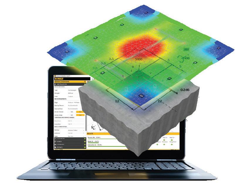
BASEPLATE THICKNESS CALCULATOR
(FINITE ELEMENT ANALYSIS TOOL)
This tool discretizes the baseplate into elements to calculate and check the thickness to determine when the plate is sufficiently rigid. A heat map is generated to highlight the distribution of the stresses on the plate.

target is to specify global warming potential targets for each class of concrete. This concept is relatively new for the industry and typically requires some amount of education for the design and construction team to successfully implement. Like other performance-based criteria, it also requires data to be submitted to the structural engineer by the mix supplier to ensure conformance. The availability of this data (see sidebar on page 14) has been growing exponentially but is still a new concept for some suppliers and may not be available for every mix. A significant amount of lead time may be required if you are targeting a significantly lower value than the national or regional benchmarks as established by the NRMCA. There are inherently two components to specifying a global warming potential target. One is transparency and data, creating the information engineers need to understand what the emissions are for a mix and inform decision-making. The second is to push the industry to develop lower-carbon emitting solutions. We should be leaning on the innovativeness of the supplier to produce new mixes both with the tools and materials they have available and looking for new materials and procedures to meet the demands of project specifications.
To meet an embodied carbon goal, along with performance and life safety criteria already demanded of suppliers and contractors, it becomes even more essential than ever to allow flexibility and control for the ready-mix supplier through an overall performance-based approach to the concrete specifications.
The best way to achieve an embodied carbon goal, or other project requirements for your concrete scope, is through the use of performancebased specifications. They allow for specification of a direct measure of embodied carbon: a global warming potential limit supported by an environmental product declaration. For detailed supplemental information on all the concrete mix design properties discussed in this article, refer to the Performance-Based Concrete Specification Guidance: Concrete Class Table published on the NCSEA website by the NCSEA Sustainable Design Committee. Take this document and start to have discussions with your project teams. Better yet, start having conversations with your local concrete suppliers about their capabilities when it comes to low embodied carbon concrete. For the ideas proposed in this article to be successful, it requires increasing our ability to specify the appropriate tests and trust the data that we receive. It also requires suppliers to understand the testing requirements and early communication among all stakeholders to optimize mixes and perform additional testing as required to meet the needs of the specification without resorting back to traditional prescriptive based approaches.

Using the code provisions as intended, without any additional factors of safety, will result in structural designs that inherently meet the stability safety objectives.
By Jaspal Singh Saini, PE
The methodology for analyzing and designing building structures using specified loads and load combinations in the International Building Code (IBC) and ASCE 7 Minimum Design Loads and Associated Criteria for Buildings and Other Structures has undergone significant evolution over the years. Structural engineering practice has progressively transitioned from traditional allowable stress design methods to reliability-based strength design methods. The updates in IBC and ASCE 7 aim to allow a consistent set of load combinations throughout the entire design engineering lifecycle. For assessments related to overturning and sliding stability, irrespective of the building risk and seismic design categories, seeing a factor of safety of 1.5 has been a norm for structural engineers throughout the U.S., particularly for those accustomed to traditional approaches. Design coordination with geotechnical engineers in the building industry who typically follow allowable or working stress design practices and require a minimum factor of safety of 1.5 for soil slope stability failures under sustained loads may also reinforce this opinion. Despite the well-intentioned nature of the IBC and ASCE 7 code revisions, they are often misinterpreted/misunderstood when evaluating the stability of structures against overturning and sliding.
Sections 7.2.9 and 7.2.10 of ASCE 41-23 Seismic Evaluation and Retrofit of Existing Buildings require that the minimum factor of safety of 1.0 shall be used for the overturning and sliding checks for seismic evaluation of existing buildings; ASCE 41-23 commentary clarifies that these requirements are “consistent with prevailing practice specified in current codes for new buildings”. Furthermore, Section 5.3.5 of ASCE Report Seismic Evaluation and Design of Petrochemical and Other Industrial Facilities mentions that the minimum factor of safety for overturning and sliding stability checks for seismic loads shall be 1.0 for petrochemical and other industrial facilities and recommends using the alternative allowable stress design (ASD) load combinations in IBC. However, quantitative structural stability requirements in IBC (2024) and ASCE 7-22—the codes of record for analysis and design of new building structures—are only provided in IBC Section 1807.2, which stipulates that the retaining walls shall be designed to produce a stability factor of safety (called safety factor in IBC) of 1.5 for nominal [or service] loads. Does this mean that new building structures are exempted from the global structural overturning and sliding stability checks, and have IBC and ASCE 7 always been silent on the required factor of safety for stability calculations for new building structures? The answer is obviously no for both questions. IBC (2024) Section 1605.1.1 states
that “where overall structural stability … is being verified, use of load combinations specified in Section 2.3 or 2.4 of ASCE 7, and in Section 1605.2 shall be permitted”. ASCE 7-22 Section 1.3 requires that the building structural systems “… shall be designed and constructed with adequate strength and stiffness to provide structural stability …” and “… designed to resist forces caused by earthquakes, wind, and tornadoes, with consideration of overturning, sliding, and uplift …” However, these standards do not provide any explicit requirement for the required factor of safety for these checks for new building structures. A quick review of the evolution of building codes shows that ASCE 7 used to contain explicit stability check requirements just a few decades ago, but those requirements were removed with the migration from the allowable stress design approach towards the reliability-based strength design methods.
ASCE 7-95 Section 2.4.4, applicable to load combinations for allowable (or working) stress design for service level loads, required that “Buildings and other structures shall be designed so that the overturning moment due to lateral forces…does not exceed two-thirds of the dead load stabilizing moment… The base shear due to lateral forces (wind or flood) shall not exceed two-thirds of the total resisting force due to friction and adhesion...” This ASCE 7-95 provision meant that a minimum factor of safety of 1.5 was required for service level loads. Similar requirements were not explicitly included or deemed necessary
either in ASCE 7-95 Section 2.3 pertaining to load combinations for strength design or in the UBC-1997.
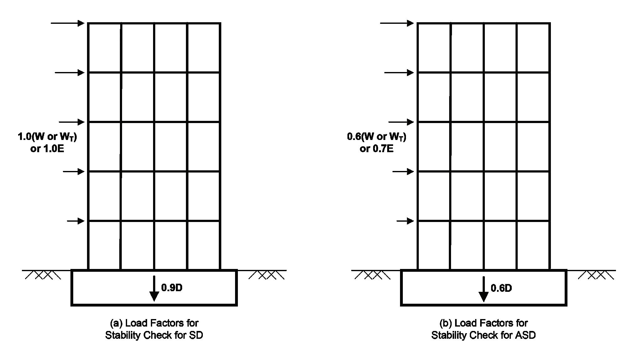
The code updates in ASCE 7-98 revised Section 2.4.4 to remove the above requirement but added two new allowable stress design load combinations involving 0.6D+W and 0.6D+0.7E, where D, W, and E represent dead loads, wind loads, and seismic loads, respectively, to supplement the existing D+W and D+0.7E load combinations; it is noted that basic wind loads were at service level and basic earthquake loads were at strength level in ASCE 7-98. The intent of these changes was that the use of 0.6D implicitly provides a factor of safety exceeding 1.5 for service level lateral loads when using the allowable stress design method. The commentary to ASCE 7-98 noted that these new load combinations are to “eliminate inconsistency in the treatment of counteracting loads in allowable stress design and strength design and emphasize the importance of checking stability.” In principle, these provisions have remained the same until now, with the only change occurring in ASCE 7-10 when the wind loads were defined to be at strength level, thus, necessitating the redefinition of both strength design and allowable stress design load combinations involving wind loads. Additionally, ASCE 7-22 now includes tornado loads (W T ) in addition to wind loads. IBC standards since their inception have also followed the framework of UBC standards with no specific quantitative requirements for stability checks of building structures except for the retaining walls, as noted earlier.
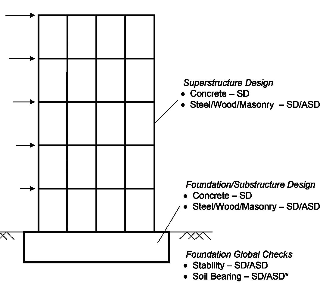
IBC (2024) and ASCE 7-22 prescribe two sets of load combinations, one for the strength design and the other for allowable stress design. Different material design standards, such as American Institute of Steel Construction (AISC), American Concrete Institute (ACI), National Design Specification (NDS), and The Masonry Society (TMS), permit the use of different design approaches (Fig. 1). Specifically, AISC, NDS,
and TMS for structural steel, wood, and masonry design, respectively, allow design engineers to use either the strength design (SD) method (called load and resistance factor design [LRFD] in AISC and NDS) or the allowable stress design (ASD) method, noting that AISC uses the “allowable strength” design method that is not formulated on traditional allowable stress based design practice though uses the allowable stress design load combinations in IBC and ASCE 7. However, ACI 318 now exclusively adopts the strength design method for concrete design and includes the strength design load combinations consistent with those in IBC and ASCE 7. In this article, the term “strength design” encompasses LRFD, and the terms “allowable stress design” and “allowable strength design” are collectively referred to as ASD. The current building codes aim to provide a comprehensive framework using either design approach, allowing structural engineers to conduct complete design evaluations, including structural stability, using either the SD or ASD method. The load combinations in IBC (2024) and ASCE 7-22 reflect this framework to lead to similar though not identical design outcomes using the two design approaches.
Based on the author’s opinion, typical design engineering firms for building structures have generally adopted the use of SD methods though some designers still prefer using the ASD methods. However, the soil checks to verify the adequacy of the subgrade supporting the buildings are typically performed for service conditions using demands based on allowable stress design load combinations irrespective of the method used to perform the design of the structural system. ASCE 7 Section 12.13.5 now includes the necessary design requirements that allows using the strength design method for soil checks and is permitted by IBC Section 1605.1.1, but this approach is still catching on in the building industry. Therefore, for analysis of the building structures, both strength design and allowable stress design load combinations are generally used and become necessary for concrete structural systems if the geotechnical capacity is based on allowable stress design.
The designers typically perform the analyses for all applicable load combinations in IBC and ASCE 7 and use the enveloping results from
the strength design load combination set and allowable stress design load combination set for various design checks. Absent any direct discussion on this topic in IBC and ASCE 7, many designers misinterpret that the traditional code intent of minimum factor of safety of 1.5 for stability for service loads applies for all allowable stress design load combinations. However, an important though unstated design objective of the building codes is that the strength design and allowable stress design load combinations involving 0.9D and 0.6D, respectively, implicitly provide a minimum factor of safety to ensure structural stability when subjected to lateral loads. Alternatively, performance-based design procedures may be used to meet the target reliabilities defined in ASCE 7 Section 1.3.1.3. For the building structure depicted in Figure 1, the structural analysis and design (including stability checks) for the wind (or tornado in ASCE 7-22) and earthquake load effects with the factored loads shown in Figure 2a for SD method and Figure 2b for ASD method implicitly meet the traditional minimum factor of safety requirements for stability. For seismic stability evaluations, the vertical load effect, not shown in Figure 2 for simplicity, shall be appropriately considered. As mentioned earlier, IBC Section 1807.2 requires the traditional minimum factor of safety of 1.5 for overturning and sliding stability of earth retaining walls for service level loads, which correspond to 1.0D+1.0H. The same objective would be automatically achieved by checking the stability of the retaining wall for the allowable stress design load combination 0.6D+1.0H or strength design load combination 0.9D+1.6H, though noting that the design of the different structural elements and soil bearing checks may still require analyses using both sets of load combinations.
The load combinations in IBC and ASCE 7 for the structural analysis and design of building structures have evolved over the years and are intended to produce a consistent design whether the strength design (SD) or allowable stress/strength design (ASD) methods are utilized. The traditional practice of maintaining a minimum factor of safety of 1.5 against overturning and sliding failures is only meant for situations where the evaluations are based on service level (nominal) loads, such as design of retaining walls. The building codes do not specifically address factors of safety against overturning and sliding failures since the appropriate application of either strength design or allowable stress design load combinations inherently result in a stable structural design configuration; additionally, ASCE 7 provides the target reliability for stability evaluation for use of performance-based design approaches. Therefore, there is no need to apply an additional factor of safety beyond those implicit in building code requirements and, if used, will result in overconservative and inefficient designs. ■

ACI 318-25 anchoring provisions reduce conservatism, clarify usage, and account for the effects of reliability and redundancy, plus major updates to breakout calculation of reinforcing bar groups have been added.
By Kenton McBride, Ph.D, PE
"Anchorage” in concrete is a broadly used term that can refer to concrete members, including pre-stressing anchorage devices, connections between concrete members via reinforcing bars, and connections between steel and concrete members via steel anchoring elements. While these various anchorage types possess common principles in force transfer, they have traditionally been treated as mutually exclusive in code provisions.
The American Concrete Institute’s ACI 318-25, Building Code Requirements for Structural Concrete, introduces major changes to the anchorage of steel-to-concrete and reinforcing bar connections. In addition to updates to factors within existing equations, steps toward recognizing the commonalities between steel/concrete and concrete/ concrete anchorage in "Chapter 17: Anchoring to Concrete and Chapter 25: Reinforcement Details" have been made.
This article focuses on major changes relating to anchorage in ACI 318-25 Chapter 17 and Chapter 25. Changes to Chapter 17 address inefficiencies and reliability concepts, while changes to Chapter 25 include new bridging provisions to Chapter 17 in the treatment of concrete breakout failure.
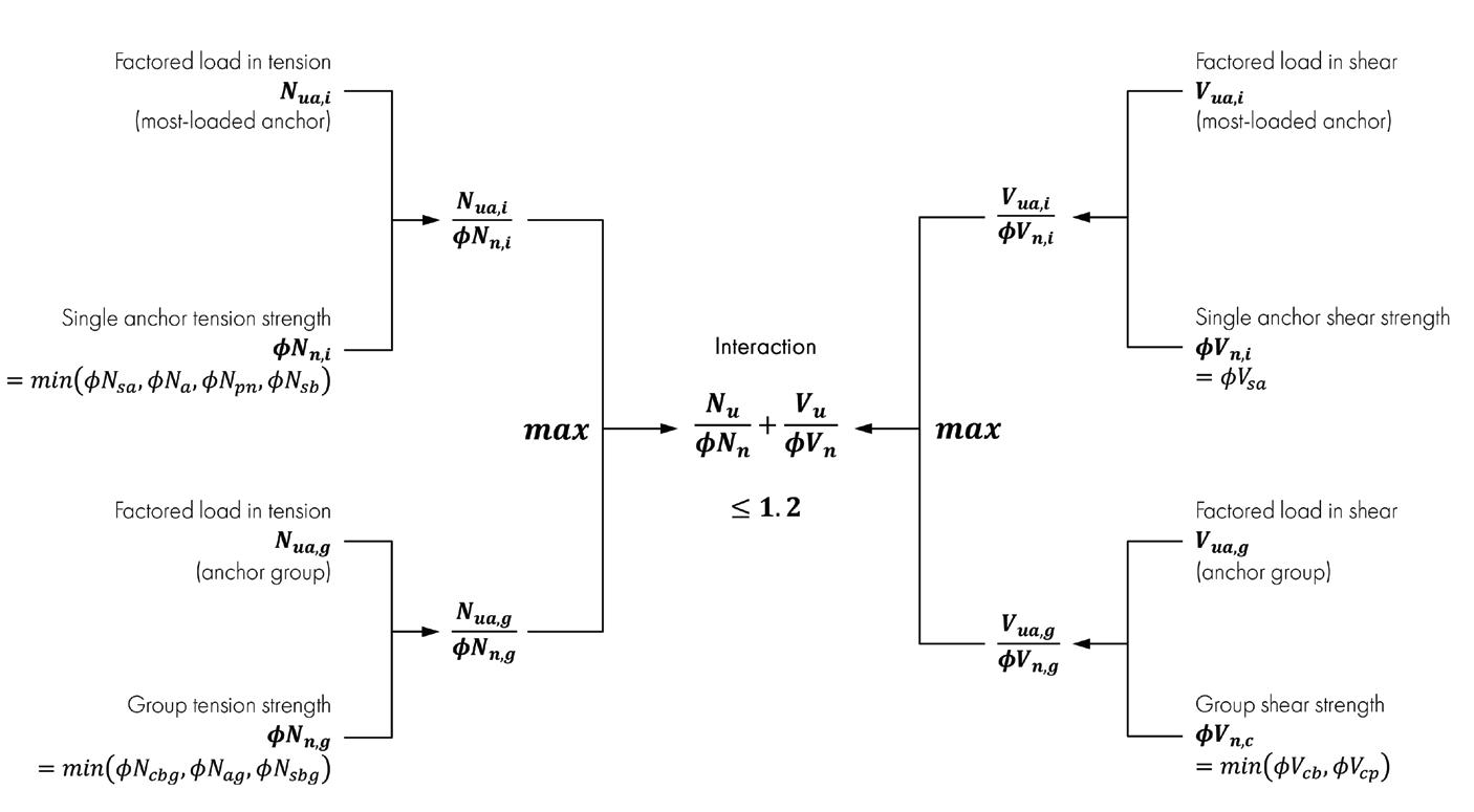
ACI 318 Chapter 17 provides design requirements for anchorage between steel and concrete members. The scope of Chapter 17 includes cast-in headed anchors, post-installed mechanical and adhesive anchors, and shear lugs. Failure modes incorporated into Chapter 17 for shear and tension design checks are summarized in Table 17.5.2. Section 17.8 addresses interaction between tension and shear failure modes.
This section examines five major changes to the design provisions:
Change 1: Updates to safety factors.
Change 2: Introduction of a beneficial overturning moment term.
Change 3: Beneficial separation of concrete and steel failure modes in interaction equations.
Change 4: Permissible use of new Chapter 25 factors for use of existing reinforcement.
Change 5: Clarifications on use of reinforcing bars as anchor reinforcement.
In addition to the five technical changes presented, clarifying editorial changes have been made throughout Chapter 17.
In ACI 318-19, the strength reduction factors, ϕ, for anchorage are defined in Chapter 17 in contrast to other Chapters whose ϕ factors are housed in Chapter 21. The Chapter 17 factors were primarily separated to address product-specific sensitivity and reliability characteristics via
an “Anchor Category” assignment from qualification.
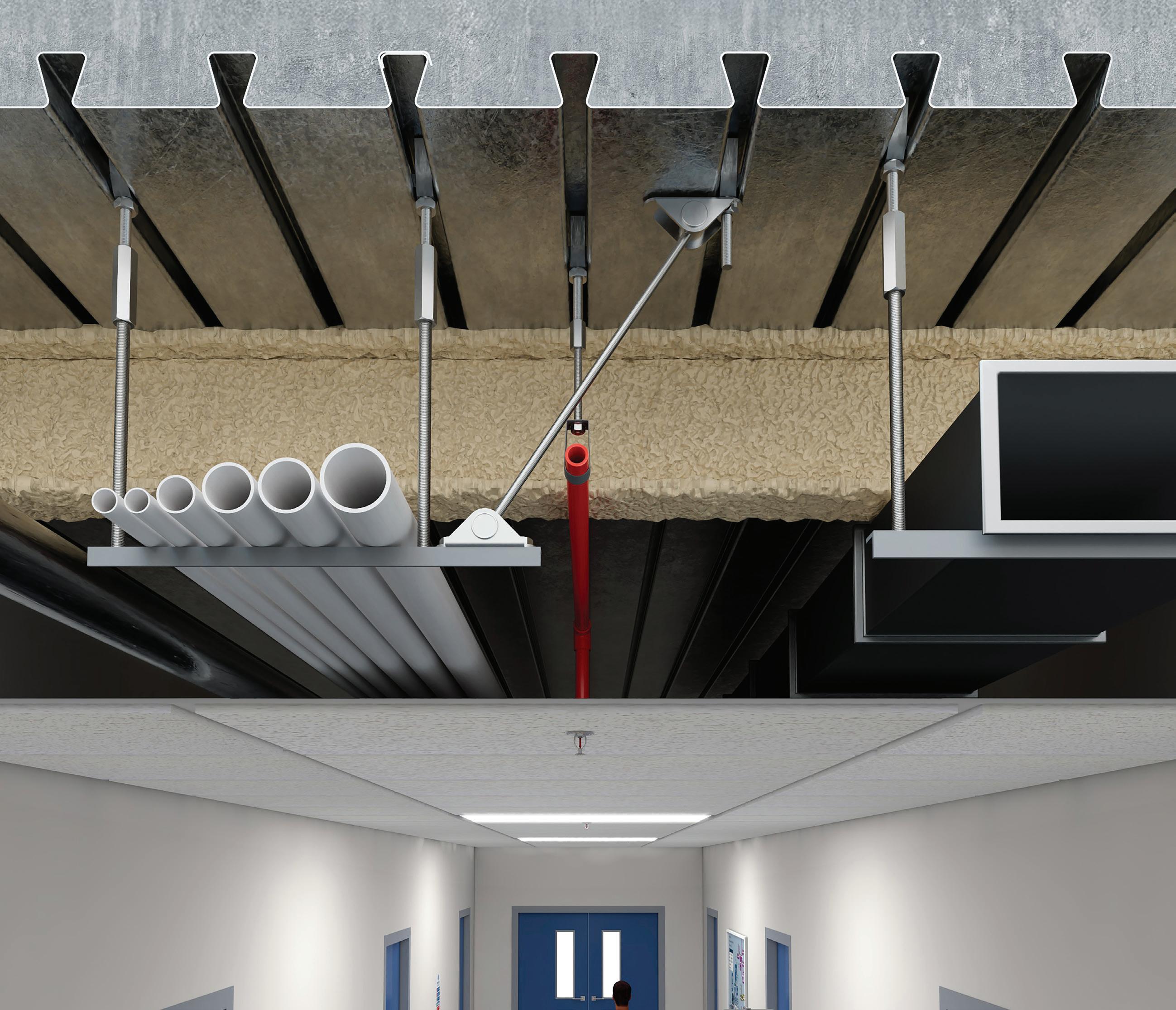
In ACI 318-25, ϕ factors have been moved to Chapter 21 to be consistent with the remainder of the document. Anchor Category adjustments and the supplementary reinforcement condition have been decoupled from ϕ and separated into a new modification factor, ψa. All equations relating to concrete failure modes for post-installed mechanical or adhesive anchors have now been changed to incorporate this additional ψa factor. Finally, a new distinction between redundant and non-redundant fastenings has been made, providing a capacity benefit for fastenings that are considered redundant. Commentary on the redundancy of anchors is provided in a revised R17.5.3, which states that “Redundancy may be assumed where it can be shown that failure of a single anchor or anchorage point does not result in loss of position retention or progressive collapse.” While every case will require engineering judgment to determine whether a fastening is redundant or not, an example of a redundant fastening might be a line of single-point fastenings of a pipe to a ceiling where failure of any individual anchor does not result in progressive failure of nearby anchors or failure of any other component in the load path. Another example in a group of anchors might be demonstrating that failure of any individual anchor will not cause failure of the anchor group, the base plate, or any components within the load path.
Table 1 provides the new anchor-related ϕ factors in Chapter 21 in ACI 318-25. Table 2 compares the outputs of the new ϕ∙ψa product for concrete tension failure modes in ACI 318-25 compared to the equivalent ϕ factor in ACI 318-19. It can be observed that the ϕ∙ψa product for redundant connections in ACI 318-25 is roughly equivalent to the ϕ factors in ACI 318-19, while the capacities of non-redundant connections are reduced by 10 to 15 percent. Table 3 compares the safety outputs between the two code editions for concrete shear failure modes.
1. New Anchor-related Factors in ACI 318-25 Chapter 21
Table 2. Comparison Between 2019 and 2025 Safety Factors for Concrete Tension Failure Modes in Chapter 17
Table 3. Comparison Between 2019 and 2025 Safety Factors for Concrete Shear Failure Modes in Chapter 17
*Supplementary reinforcement factors do not apply to pullout strength in ACI 318-19, but do apply to pullout strength in ACI 318-25.
Chapter 17 Change 2: Introduction of a Beneficial Term to Account for Compression Due to Connection Overturning Moment
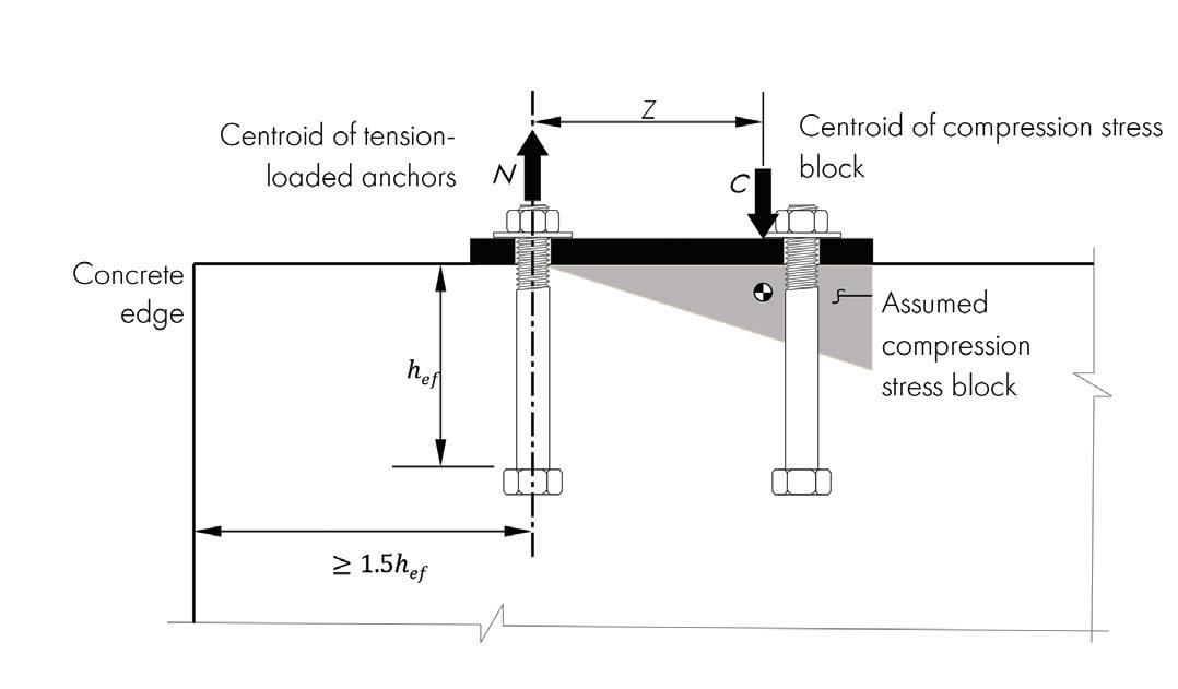
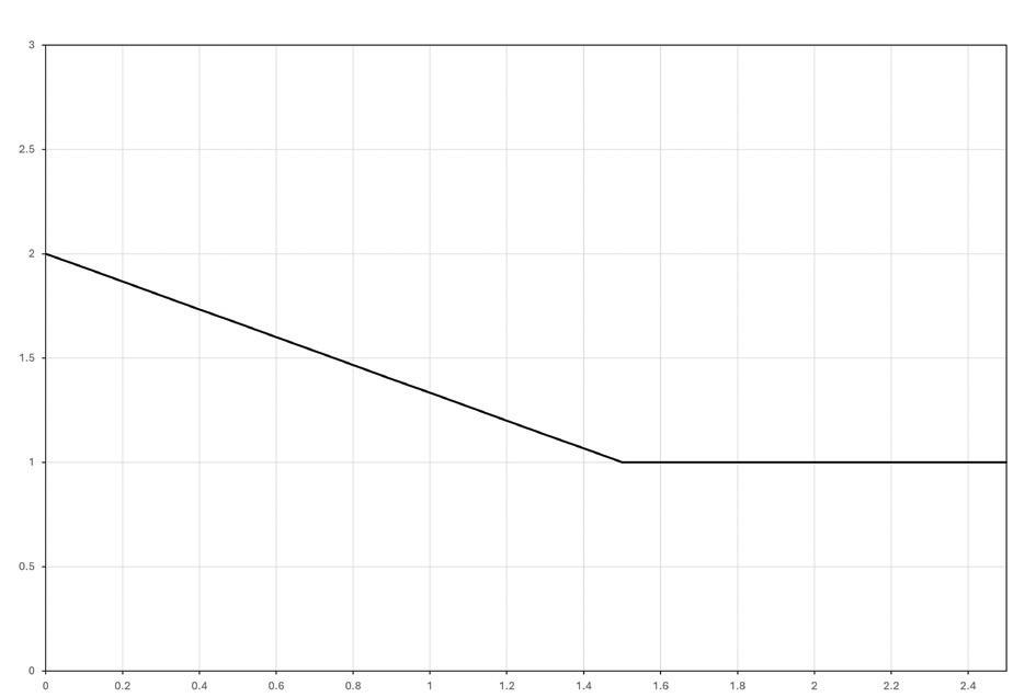
ACI 318-25 introduces a new strength-increasing factor, ψcm,N, in Section 17.6.2.7 for concrete breakout in tension to account for the positive influence of the compressive toe of an overturning connection moment. While the behavior described by this factor is related in principle to a concrete strut, it does not function the same because the anchorage condition includes an unconfined concrete surface that does not produce the same triaxial stress state as a strut within a concrete mass. The new Equation (17.6.2.7.1) is provided below. 2 1.5h z 1.0
Figure 1 (left) illustrates the variables included in the calculation of ψcm,N and Figure 1 (right) shows the influence of the ratio of the internal lever arm to the embedment depth of the anchor group.
Chapter 17 Change 3: Beneficial Separation of Failure Modes in Interaction Equations
ACI 318-19 conservatively simplifies the interaction between tensile and shear failure modes by determining the governing tensile failure mode
and the governing shear failure mode and combining them into a single interaction equation. By reducing all failure modes to a single interaction equation, ACI 318-19 allows for the possibility that a governing concrete failure mode interacts with a governing steel failure mode. A flowchart of the interaction between tension and shear in ACI 318-19 is shown in Figure 2.
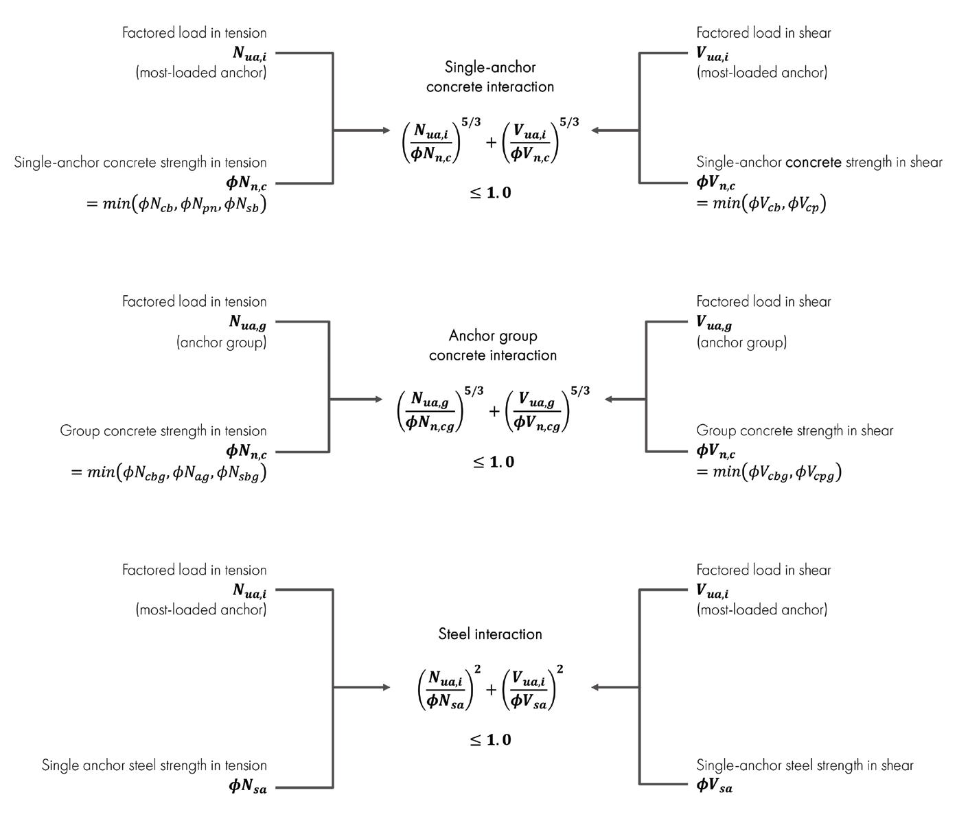
However, it is well understood that concrete failure modes only interact with other concrete failure modes and steel failure modes only interact with other steel failure modes. Recognizing that concrete and steel failure modes behave separately and also recognizing that a simplified interaction calculation is not necessary to simplify the design process, ACI 318-25 separates interaction into three equations, one for concrete failure of individual anchors, one for concrete failure of anchor groups, and one for steel failure. By separating steel and concrete interaction, unnecessary conservatism is removed, producing more efficient designs in many cases. A flowchart of the interaction between tension and shear in ACI 318-25 is shown in Figure 3.
The use of the new Chapter 25 Eq. (25.4.11.2) is permitted to be used for calculation of tensile breakout capacity of anchors in the new Section 17.1.9 of ACI 318-25. See the “Change 1” section of Chapter 25. When
using Eq. (25.4.11.2) in a Chapter 17 design, the following notable requirements and restrictions apply:
• The k c factors used for the determination of N cpg are the same as are used for Chapter 17 design in contrast to the higher permitted k c factors used in the Eq. (25.4.11.2) design.
• The factor relating to concrete cracking, ψc,N, is permitted to be greater than 1.0 in accordance with Chapter 17.
• Factor ψa is determined in accordance with Chapter 17. The “distributed reinforcement” term N srg cannot be used in combination with the “anchor reinforcement” provisions of Chapter 17.
The anchor reinforcement provisions in ACI 318 Chapter 17 permit concrete breakout calculations to be omitted and replaced with steel
calculations of special reinforcing bars when those bars comply with the geometric requirements of Section 17.5.2.1. Two clarifying technical changes are made in the use of reinforcing bars as anchor reinforcement.
Section 17.5.2.1 is now split into two subsections 17.5.2.1.1 and 17.5.2.1.2 for anchor reinforcement meant to intercept tension and shear breakout, respectively. In both subsections, a clarifying component (b) states that anchor reinforcement legs must be parallel to the direction of the applied load. New Section 17.5.2.1.3 further clarifies that where anchor reinforcement meeting the requirements of 17.5.2.1 are not oriented parallel to the load, only the parallel component of the reinforcing bars is permitted to contribute to the strength calculation of the anchor reinforcement.
A new Section 17.5.2.1.4 states that the shear friction calculations of Section 22.9 cannot be used in the design of anchor reinforcement. This translates to the prohibition of the use of shear friction calculations to replace concrete breakout calculations in tension and shear.
Anchorage of reinforcing bars typically applies to the connection between two concrete structural members, e.g., between columns and foundations. This section examines two major changes to the design provisions: Change 1: Design requirements for breakout of reinforcing bar groups Change 2: Updates to hooked-bar and headed-bar development length equations
Other changes to Chapter 25 not expanded upon within this article include updates to coupler qualification and classification requirements and editorial changes throughout the chapter.
ACI 318-19 Section 17.1.6 states that consideration of breakout of reinforcing bar groups is required. However, it does not provide solutions for determining the breakout capacity that incorporate the proper safety levels for the problem of reinforcing bar groups, leaving all such consideration to engineering judgment.
ACI 318-25 introduces a major expansion to the provisions for breakout of reinforcing bar groups by providing explicit equations in new Section 25.4.11 at a safety level corresponding to existing Chapter 25 development length equations. Equation (25.4.11.2) provides the basic expression for the breakout capacity of reinforcing bar groups, incorporating a concrete contribution term, N cpg , and a steel contribution term, N srg
N cpg is calculated using the breakout equation in Section 17.6.2 with the following modifications:
A ϕ factor of 0.90 is assigned to the breakout capacity, in contrast with lower ϕ factors for Chapter 17 design. The author infers ψa =1.0 in this calculation (see Chapter 17 Change 1).
The concrete effectiveness factor, kc, is permitted to be taken as 35 for straight reinforcing bars and 40 for hooked and headed reinforcing bars OR Eq. 17.6.2.2.3 is permitted to be used with an additional increase factor of 5/3.
The cracked concrete factor ψc,N is always taken as 1.0, as the kc factors above already incorporate the uncracked concrete condition. The uncracked concrete condition is accepted in these provisions because reinforcing bar anchorage includes longer embedments than shallow anchors that are much more affected by bisecting cracks.
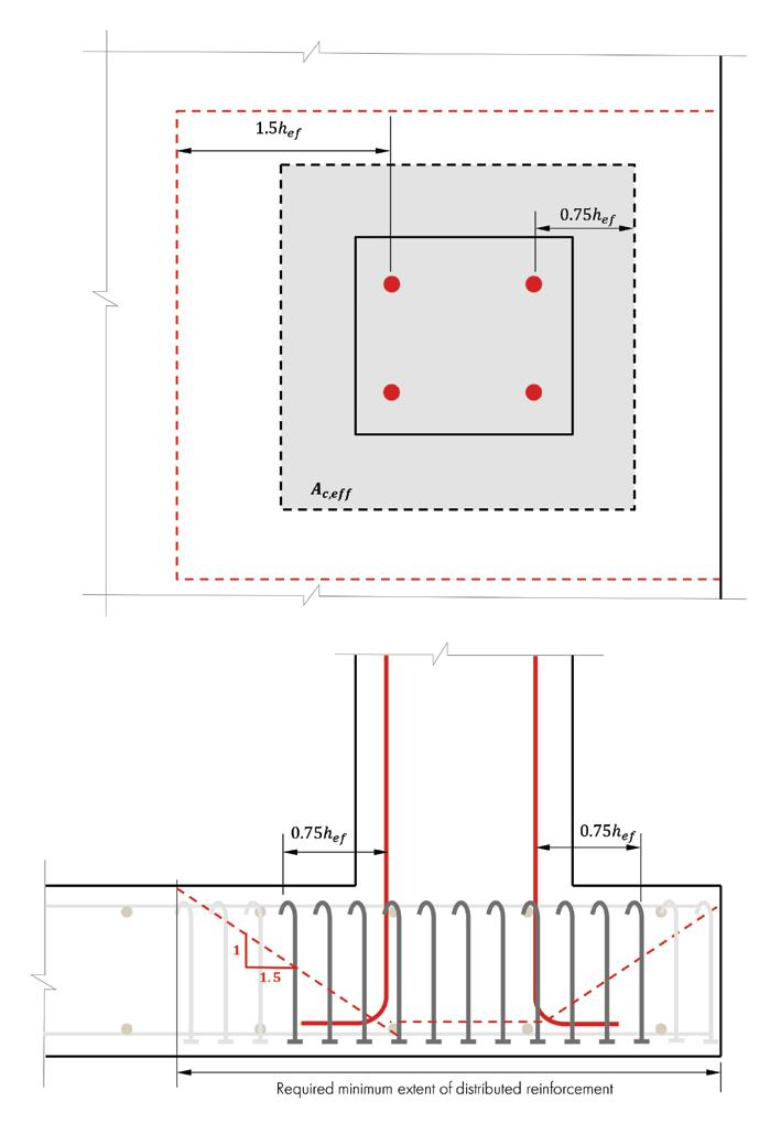
N srg is defined by ACI 318-25 Eq. (25.4.11.5) and applies to “distributed reinforcement” with the following properties illustrated by Figure 4:
Distributed reinforcement does not have a larger diameter than the anchored bars, is headed or hooked at the embedded end, and is oriented parallel to the anchored bars within the area Ac,eff
Spacing of distributed reinforcement is no greater than 0.25hef for N rg>2.5Ncbg and no greater than 0.5hef for N rg≤2.5Ncbg
Distributed reinforcement extends over 90% of the embedment of the bar group and terminates beyond the embedded end of the bar group.
In ACI 318-25 Equation (25..4.11.5), ρt is the average reinforcing ratio within the potential breakout surface; Ac,eff is the area defined by dimensions in both directions not exceeding 0.75hef from outside anchors and the distance from those anchors to the edge of the concrete, whichever is less, as illustrated in Figure 4; and f y is the nominal yield strength of the distributed reinforcement.
Hooked and headed reinforcing groups are subject to the breakout calculation requirements described in the Change 1 section above. In addition to the newly required breakout calculation checks, both of the basic equations for development length have changed as described in this section.
ACI 318-19 conservatively increased the development length of hooked bars in comparison to ACI 318-14 and prior editions. ACI 318-25 has refined the hooked-bar development equation to return to the same basic development length equation as ACI 318-14, but incorporating adjusted modification factors, including a new modification factor for size effect.


2019 ,, . min f f din r 86 50 ' dh c ye b oc , m } }} } =
2025 ,, min f f din86 55 ' dh c ye b s cc r , m } } }} = eo
Red text indicates a change from the preceding version. Blue text indicates a reversion to 2014 usage.
ψe Epoxy (1.0 to 1.2)
ψc Cover (0.7 to 1.0)
ψr Confining reinforcement (0.8 to 1.0)
λ Lightweight concrete (0.75 to 1.0)
ψe Epoxy (1.0 to 1.2)
ψr Confining reinforcement (1.0 to 1.6)
ψo Location (1.0 to 1.25)
ψc Concrete strength (~0.7 to 1.0)
λ Lightweight concrete (0.75 to 1.0)
ψe Epoxy (1.0 to 1.2)
ψs Size (1.0 to 1.5)
ψcc Cover (0.7 to 1.0)
ψr Confining reinforcement (0.8 to 1.0)
λ Lightweight concrete (0.75 to 1.0)
Table 5. Progression of Headed-bar Development Length Equations From 2014 Through 2025
ψe Epoxy (1.0 to 1.2)
ψc Cover (0.7 to 1.0)
ψr Confining reinforcement (0.8 to 1.0)
λ Lightweight concrete (0.75 to 1.0)
ψe Epoxy (1.0 to 1.2)
ψp Parallel tie reinforcement (1.0 to 1.6)
2019 ,, . min dt f f dd in86 75 ' c ye bb po c 15 , m } }} } = eo
2025 ,, . min f f dd in86 90 ' dt c ye po c bb 15 , m }} }} = eo
Red text indicates a change from the preceding version.
Table 4 shows the progression of the hooked-bar development length equation from 2014 through the 2025 edition. The headed-bar development length has retained its structure from the 2019 edition but has been shortened by approximately 17% by increasing the constant term in the equation’s denominator. Table 5 shows the progression of the headed-bar development length equation from 2014 through the 2025 edition.
Anchorage provisions in ACI 318 Chapters 17 and 25 have been significantly updated in the 2025 edition. In Chapter 17, several changes have been
ψo Location (1.0 to 1.25)
ψc Concrete strength (~0.7 to 1.0)
λ Lightweight concrete (0.75 to 1.0)
ψe Epoxy (1.0 to 1.2)
ψp Parallel tie reinforcement (1.0 to 1.6)
ψo Location (1.0 to 1.25)
ψc Concrete strength (~0.7 to 1.0)
λ Lightweight concrete (0.75 to 1.0)
made to reduce conservatism, clarify usage, and provide direct accounting of the effects of reliability and redundancy. In Chapter 25, a major new requirement has been added to account for the potential breakout of reinforcing bar groups while also updating the basic development length equations for hooked and headed bars. While the subject of anchorage still remains disjointed between Chapter 17 and Chapter 25, some common elements have been bridged in this newly published document. ■
Kenton McBride, Ph.D, PE, is Director of Codes and Standards at Hilti North America. He is a member of ACI committees 318-B (Anchorage and Reinforcement), ACI 355 (Anchorage to concrete) and the president of the Concrete and Masonry Anchor Manufacturers Association (CAMA).
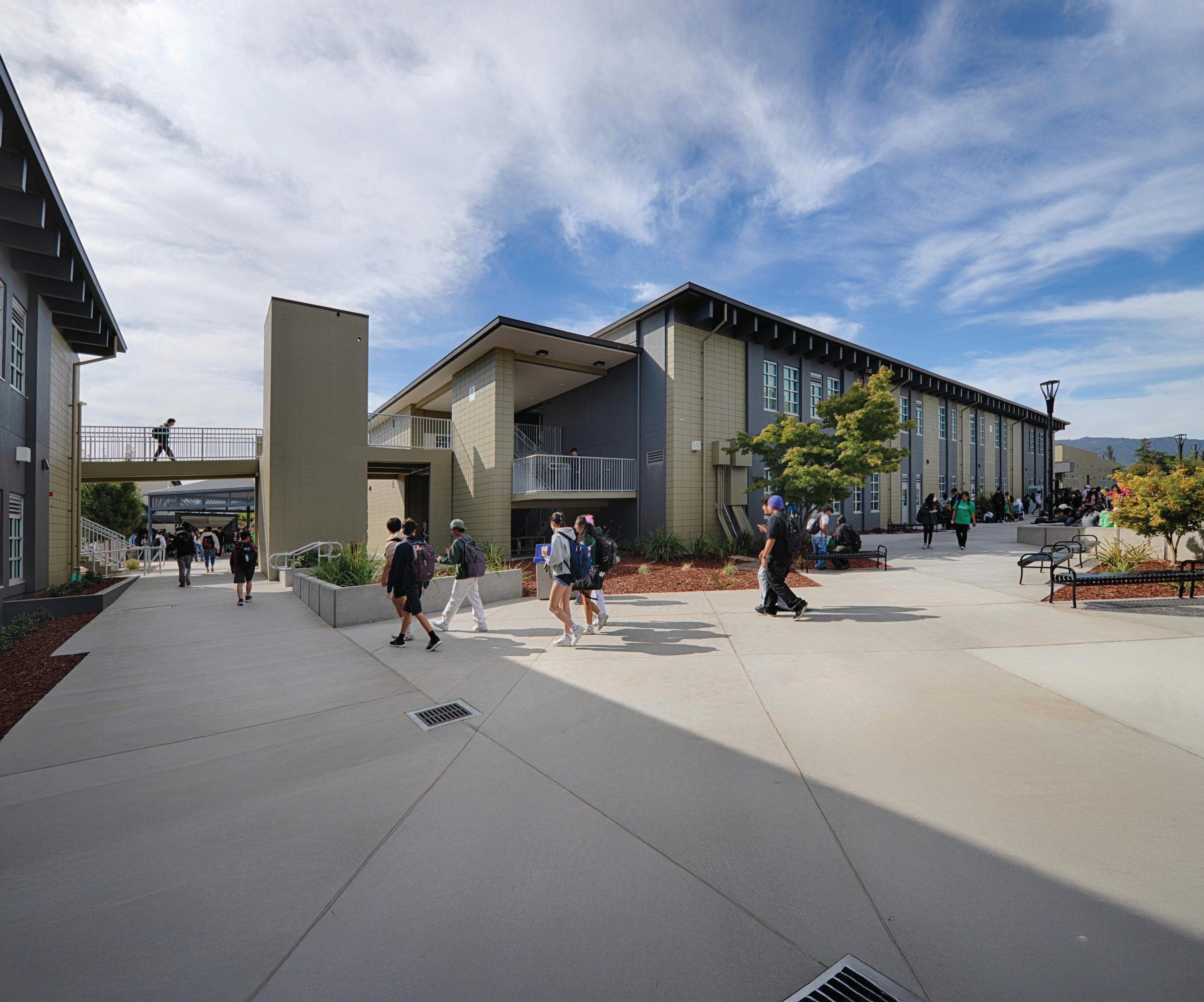
The comprehensive rehabilitation of a Silicon Valley high school used a composite solution.
By Nik Blanchette, SE, Steve Heyne, SE, and Chris Warner, SE
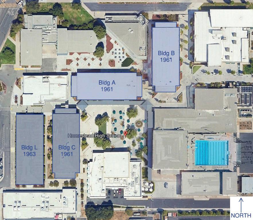
Homestead High School is in the heart of Silicon Valley, California, and has produced notable alumni like Steve Wozniak and Steve Jobs. With great innovation in its DNA, the school required an inventive, surgical retrofit to two of the campus’ original buildings, which consist of concrete masonry unit (CMU) walls with precast concrete floor and roof framing. ZFA, the SEOR for the project, identified these buildings as seismically deficient, particularly the floor and roof diaphragms, and assisted the school in pursuing state funding towards seismic strengthening. These large, heavy buildings warranted a creative approach to improve performance without adding significant seismic mass or replacing substantial elements. At the same time, low ceilings, poor ventilation, and limited natural light hindered the function of the space; a rehabilitation served to drastically improve the users’ experience day-to-day while also dramatically increasing the seismic resilience of the buildings. Originally constructed in 1962, the campus comprised eight stackedbond CMU-framed one-and-two-story buildings with precast concrete tee-beam floor and roof framing. The walls are fully grouted, steel reinforced, of various thicknesses: 8, 12, 16, and 24 inches; stackedbond is defined as aligning mortar joints from course-to-course in lieu of offsetting them (i.e. running bond). Eight-inch walls are reinforced with a single layer of reinforcing, both vertical and horizontal, whereas
thicker walls are reinforced with a double layer of rebar. Tee-beams are either 24 or 36 inches tall, reinforced with a mixture of prestressing strands, deformed bars, and welded-wire reinforcement. Heavy walls and heavy beams generate significant seismic mass, which can lead to poor seismic performance when coupled with non-ductile concrete & masonry detailing. The original scope of the rehabilitation was four of the buildings: A, B, C and L (Fig. 1), however only A and B have been modernized thus far. Buildings A, B, and C are two-stories, and L is one-story. Building L was an addition to the original campus, but it contains similar detailing to the previous structures. Bringing these buildings up to current code performance was no small task.
In 2006, California voters approved Proposition 1D to fund critically seismic deficient public-school buildings throughout the state; allocation of funding is organized through the Office of Public School Construction (OPSC) with the Division of the State Architect (DSA) reviewing and approving construction documents, including eligibility for the funding. This program is defined as the Seismic Mitigation Program (SMP). SMP provides matching funds and is a phenomenal option for school districts to improve the resiliency of their building stock for seismic hazards.
First, SMP requires an Eligibility Evaluation Report (EER) to establish qualification for the program. Qualifying buildings exhibit a critical
seismic deficiency that is expected to result in local or global collapse in the design earthquake event. Utilizing ASCE 31-03, Seismic Evaluation of Existing Buildings, DSA created a straightforward approach to screen vulnerabilities severe enough to warrant state funding: soft story, captive columns, wall anchorage deficiency, etc. The EER involves brief calculations to support the assertion of seismic deficiency. When completed, the EER is submitted to DSA for review and approval.
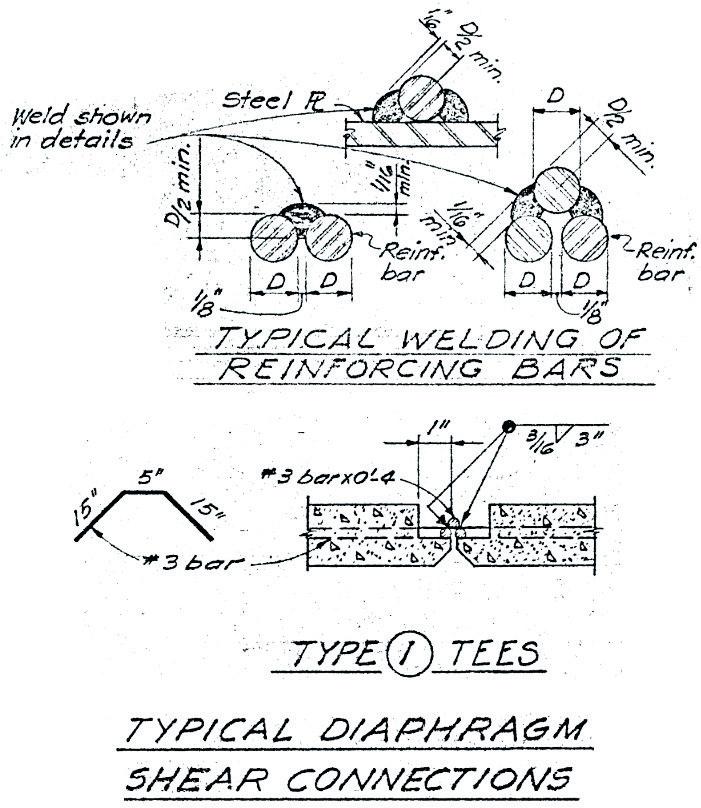
Buildings A, B, and C contained the same critical deficiency—inadequate concrete tee-beam flange interconnection for diaphragm action. At the roof, concrete tee-beam flanges, with no topping slab, acted as the diaphragm (Fig. 2). Without a topping slab, force transfer relies on welded connections between adjacent precast tee-beams. These connections consist of a piece of rebar welded, one side, to rebar embedded in adjacent beams (Fig. 3). This results in a one-sided weld that is dangerously subject to prying, which could be due to transverse loading, contraction and expansion, and/or differential prestress cable relaxation. Additionally, there is no positive attachment between the tee-beams and the perpendicular shear walls. At the floor, there is no positive attachment between the topping slab and the shear walls or collectors—load transfer between the horizontal and vertical Seismic Force Resisting System relied on concrete “blocking” panels physically
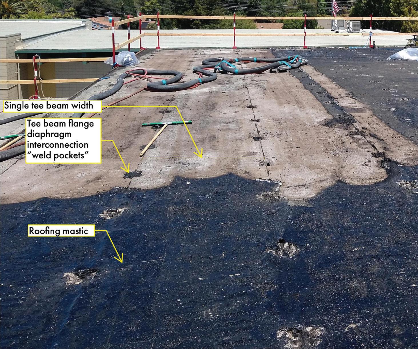
interlocking the team beam stems on top of the collector line. Of course, there are other seismic deficiencies; however, those deficiencies are not considered per EER to be something that would result in local or global collapse.
Following eligibility confirmation, an important decision for the school district is rehabilitation or replacement. If the estimated retrofit cost is equal to or greater than 50 percent of the replacement cost, then the district can obtain funding to replace the existing building with new construction. To preclude inflating the comparison cost, DSA reviews the scope of the proposed retrofit to confirm it’s the minimum amount of work necessary. If rehabilitation is the selected direction forward, the next step is the Evaluation and Design Criteria Report (EDCR).
Second, the EDCR is the designer’s opportunity to define the design criteria for the structural safety aspects of the rehabilitation project, establishing a baseline for preparation of the construction documents. Due to the dramatically different approaches available to retrofit a building, the EDCR serves to coordinate between stakeholders and DSA before the design begins. The EDCR has several key areas: potential seismic deficiencies, both structural and nonstructural; design criteria; data collection, which includes condition assessment and material testing; and geological hazards, which includes soil effects like liquefaction as well as ground shaking. A critical decision at this point is choosing between ASCE 7 Minimum Design Loads and Associated Criteria for Buildings and Other Structures and ASCE 41 Seismic Evaluation and Retrofit of Existing Buildings. Using ASCE 7 for the retrofit design requires compliance with prescriptive detailing requirements of the material reference standards, which is not typically feasible for decades-old concrete, steel, and/or masonry structures. ASCE 41 was utilized for this project due to that reason.
An EDCR is required for each building individually: a total of three were prepared for this project. The EDCR specifies what Performance Objective the project will be retrofitted to, which is in accordance with California Existing Building Code (CEBC) Section 317.5. For Risk Category III structures, DSA specifies BSE-2N and BSE-1N Seismic Hazard Levels and Limited Safety and Damage Control Performance Ranges, respectively. DSA reviews and approves the
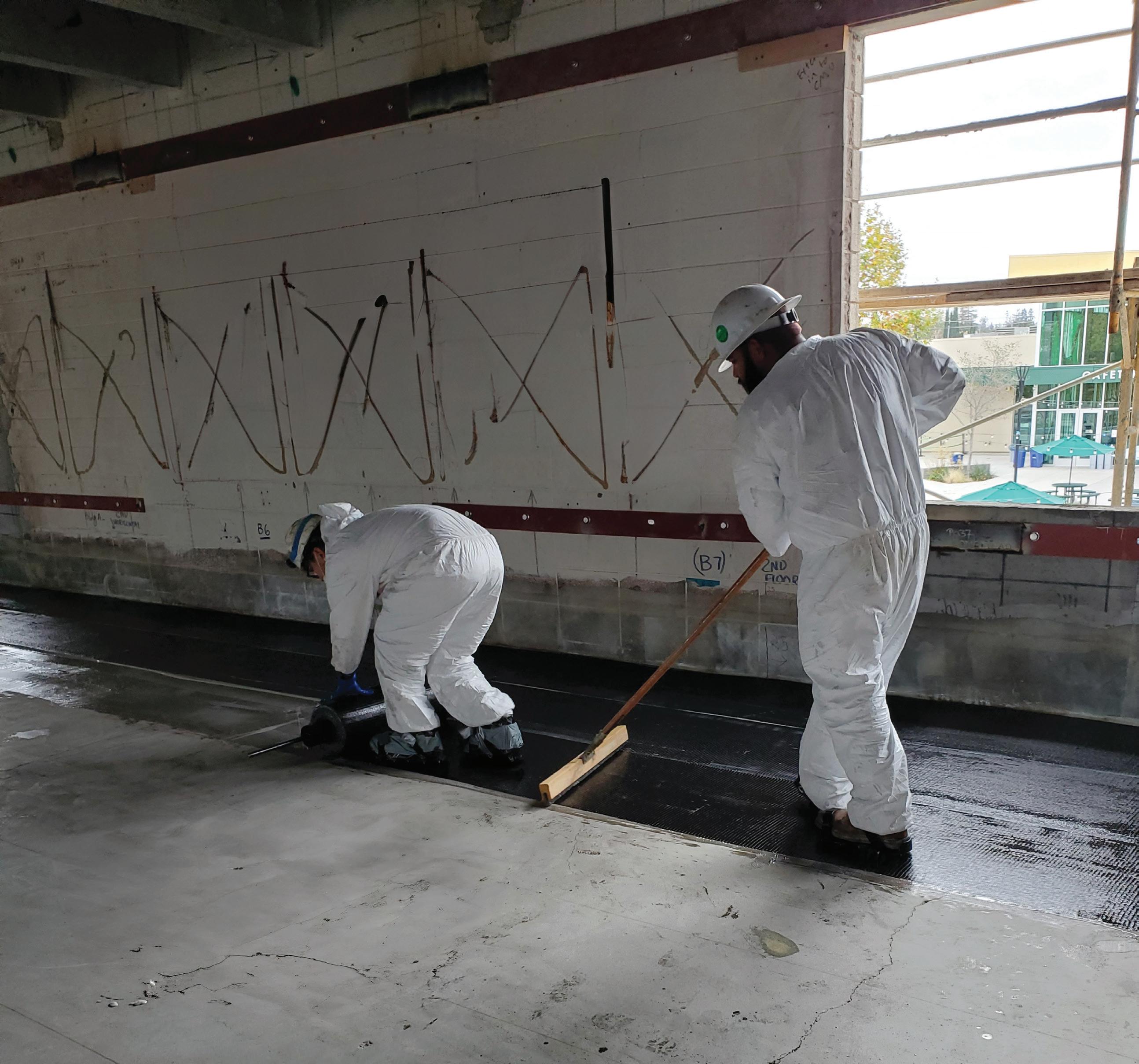
EDCR—the next step is the construction documents. Identified in the EER, the concrete tee-beams were the main culprit for poor seismic performance; various elements of the diaphragm required strengthening: out-of-plane wall anchorage, diaphragm shear & flexure, and in-plane shear transfer between diaphragm and shear wall. Several options were evaluated to improve the diaphragms: concrete overlay, horizontal steel truss, and composites. Adding new concrete would add seismic mass, which would exacerbate other seismic deficiencies. Steel would weigh less than concrete but the complicated steel connections would be costly. Composites, like Fiber-Reinforced Polymer (FRP), offer a lightweight solution to strengthening existing concrete. FRP typically consists of carbon or glass fibers combined with a liquid polymer material, such as epoxy. Simply put, adding strips of FRP to concrete acts like adding rebar, which can increase flexural strength, shear strength, and/or confine elements to improve ductility. DSA requires the approval of Alternate Design, Materials and Methods of Construction (AMM) request for the use of FRP. The engineer submits the proposed condition; a description of the requested alternate for various topics like suitability, strength, fire resistance, et cetera; and supporting documentation like preliminary calculations and manufacturer’s information. One initial discussion point with DSA was unidirectional versus bidirectional fabric.
FRP fabric typically comes in either unidirectional or bidirectional weaves. As the name suggests, the difference is the orientation of the fibers. Unidirectional fabrics have fibers primarily oriented in one direction; whereas, bidirectional has primary fibers oriented in two orthogonal directions. Unidirectional fabric is a great solution for flexural reinforcing because the tension forces are oriented in one primary direction. Bidirectional is a good option when forces may occur in more than one direction, like in diaphragms. However, overlapping orthogonal layers of unidirectional fabric can achieve strengthening in those orthogonal directions as well. Ultimately, diaphragm strengthening utilized overlapping layers of unidirectional fabric due to high demands.
At the interface of the concrete diaphragm and the CMU wall, in-plane shear transfer was deficient. Bidirectional fabric in an
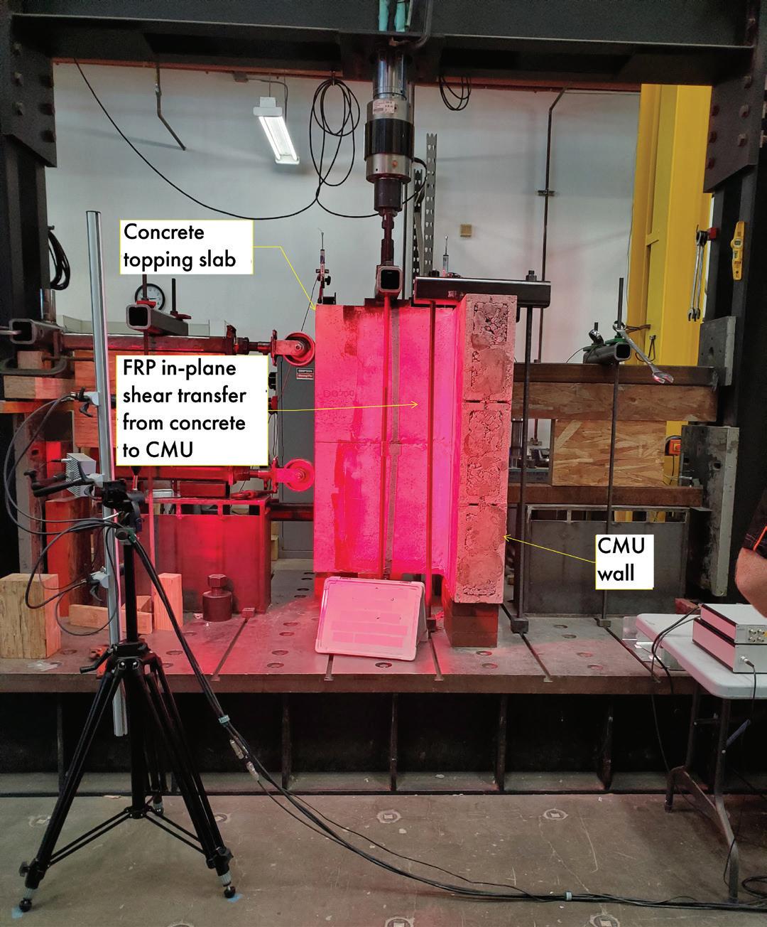
added scrutiny to the FRP strengthening because ACI 440.2R-17 Guide for the Design and Construction of Externally Bonded FRP Systems for Strengthening Concrete Structures specifies that FRP materials and specific applications are to be qualified by tests. Simpson Strong Tie (SST) is the Manufacturer of FRP solutions that was the basis of design for this project, and they had not previously tested CMU-to-concrete FRP connections. To address this condition, SST performed testing at their research and development lab in Stockton, California, to substantiate the capacity of the connection (Fig. 4). SST addressed DSA comments on their test setup and results; DSA approval would not be possible without their participation. Testing was in accordance with AC125 Concrete and Reinforced and Unreinforced Masonry Strengthening Using Externally Bonded Fiberreinforced Polymer (FRP) Composite Systems, which is the basis for ICC-ES approval. SST fabricated five specimens to recreate a segment of the existing CMU wall and concrete diaphragm, to which the proposed FRP connection was added. Installation of FRP matched project specifications, such as the surface preparation and the paste radius to smooth out the right angle between wall and diaphragm. Load was applied cyclically to the concrete stem, with a push-pull cycle of one kip-per-second load rate. Per AC125, load reversal was applied at increments of 25% of the anticipated ultimate failure load. Per ASCE 41, the lower bound strength calculated from the test results was the average maximum strength minus one standard deviation. For one layer of bidirectional fabric, 12.5 inches wide, this was 4.8 kips per foot of capacity, which was only a six percent reduction from calculated capacity. With shear transfer resolved, the next problem to solve was collector forces.
FRP solved a great number of challenges in the seismic retrofit of these buildings; however, another solution was utilized for strengthening of collectors and in-plane shear transfer in some locations—steel (Fig. 5). Steel was a viable option for collectors specifically due to their isolated locations, which allowed for localized swaths of material; unlike the diaphragm that involved the entire area of the floor. FRP was considered for collector strengthening but the enormous seismic mass of the buildings produced such large collector forces that steel was more economical. Steel plates, field welded together to allow
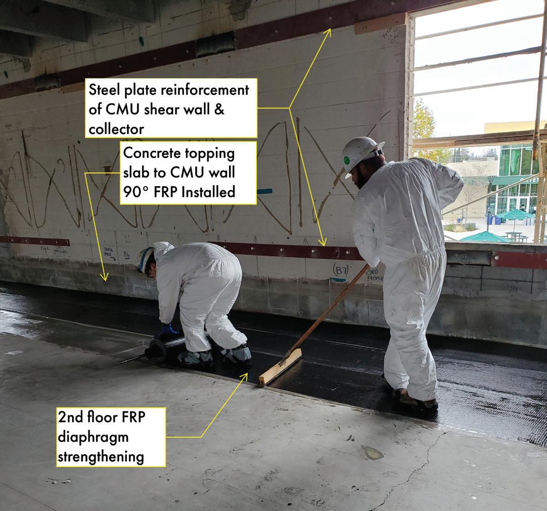
the Contractor to select their splice locations, were anchored to the existing collectors with screw anchor bolts at 24 inches-on-center, to provide strengthening in both compression and tension. Similarly at transverse walls, in-plane shear strengthening was achieved using bent steel plates bolted to the diaphragm and connected to the wall with screw anchor bolts. In addition to the dramatic structural upgrades, nonstructural improvements were a crucial piece of this project. Nonstructural connections to tee-beams warranted extreme scrutiny to avoid prestressing strands. Typical prestressing strands sweep from full depth at supports to the bottom approximately 25 percent at midspan with around 1.5 inches of clear cover, leaving little room to embed fasteners. A product relatively new at the time to receiving ICC-ES approval, Hilti HDI-P TZ drop-in anchors were extensively used due to the incredibly shallow hole depth – ¾ inch. In most nonstructural anchorage conditions, like cold-formed steel wall framing or folding partition support, the drop-in anchors allowed installation without locating the prestressing strands due to the lack of conflict. Nonstructural components like mechanical, plumbing, and/or fire protection warranted a screw anchor connection due to the larger mass; screw anchors required coordination with prestressing strands to ensure none would be cut. New penetrations through tee beams were another item that required close coordination. Vertical penetrations through tee beams were carefully located to avoid existing connections and incorporate with new FRP strengthening. Incorporating nonstructural anchorage into the structural drawings added scope of work but ultimately helped preclude unfortunate surprises in construction. These rehabilitated buildings, standing at 62 years old, offer a phenomenal learning space for the campus. SMP provided matching funds to achieve this work, which was a tremendous opportunity for the school district to maintain the original form of the campus while achieving current code equivalent building performance. FRP demonstrated itself as an incredible solution to mitigate critical seismic deficiencies while not adding burden to any other structural elements—a key aspect of retrofitting heavy buildings. ■
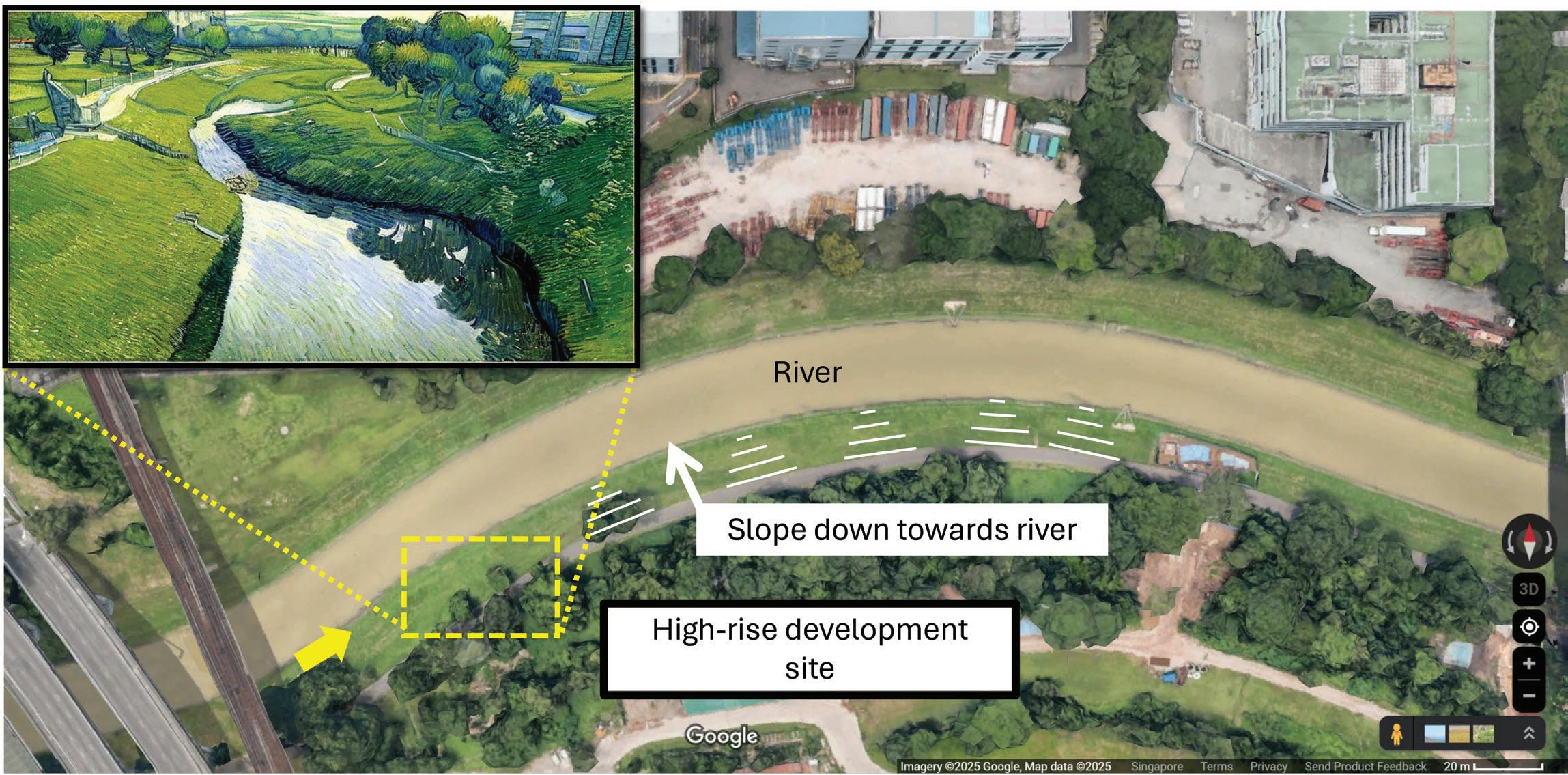
A landslide incident on a gentle slope serves as a reminder of the importance of site investigation, desk study, and checking of overall global stability.
By Hee Yang Ng, PE
Ahigh-rise waterfront residential development with ancillary facilities was proposed near a riverbank (Fig. 1). The tower block was located at the top of a gentle 10-meter-high slope with the toe of the slope meeting a flowing river. Site investigation boreholes were carried out at the tower block location and results showed good ground conditions with no presence of soft
soils. Nonetheless, as the tower loadings were high, pile foundation was proposed for the tower. To facilitate the construction of the ancillary facilities consisting of light-weight structures, a retaining wall (Fig. 2) was designed to be placed at the mid-height of the slope with the top of the retaining wall meeting the platform level of the tower block. This created flat, usable space on the slope. The retaining wall base was designed to rest on grade without any piles. Halfway into the construction of the retaining wall, a landslide occurred causing soil to be displaced into the river. The upward heaving of the riverbed even disrupted the fluency of the river flow. The retaining wall collapsed and a footpath along the river side was damaged. It was fortunate that the tower block remained intact and was unaffected by the incident. One passer-by sustained minor injuries. Post-failure investigations, which included drilling
42 additional boreholes extending to the riverbank, revealed a failure surface cutting below the slope and running through a layer of soft soil. How did a seemingly safe and “gentle” slope fail suddenly? What are the lessons learned from this episode?
The importance of site investigation in any developmental project involving the ground cannot be overemphasized. Without site investigation, it is difficult to know the stra tigraphy and ascertain the appropriate ground parameters for design. Equally important, the presence of adverse ground conditions such as soft soils may be overlooked. Undetected soft soils have shown up in many cases to be problematic such as causing settlement and displacement issues. Many engineers are careful to insist on site investigation for high-rise buildings but sometimes become complacent when designing retaining walls, especially when the retaining height is not high. Codes usually give a generic guide on the number and depth of boreholes. For example, FHWA (Federal Highway Administration) (2002) recommended “a minimum of one boring should be performed for each retaining wall." For retaining walls more than 30 m in length, the spacing between borings should be no greater than 60 meters. Similarly, in Eurocode 7 (EC7), for linear structure (roads, railways, channels, pipelines, dikes, tunnels and retaining wall), a spacing of 20–200 meters is required. It is important to note a single point information below the retaining wall base would not provide sufficient information to establish a section profile where ground conditions may differ in front and behind the wall. This is why in Eurocode 7-2, “for structures on or near slopes and steps in terrain (including excavation), investigation points should also be arranged outside the project area, these being located so that the stability of the slope or cut can be assessed.”
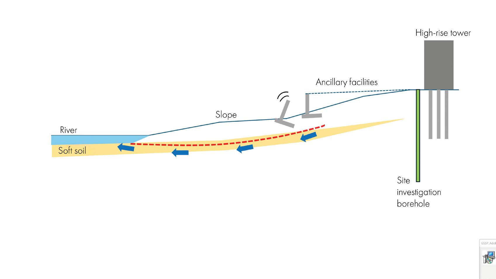
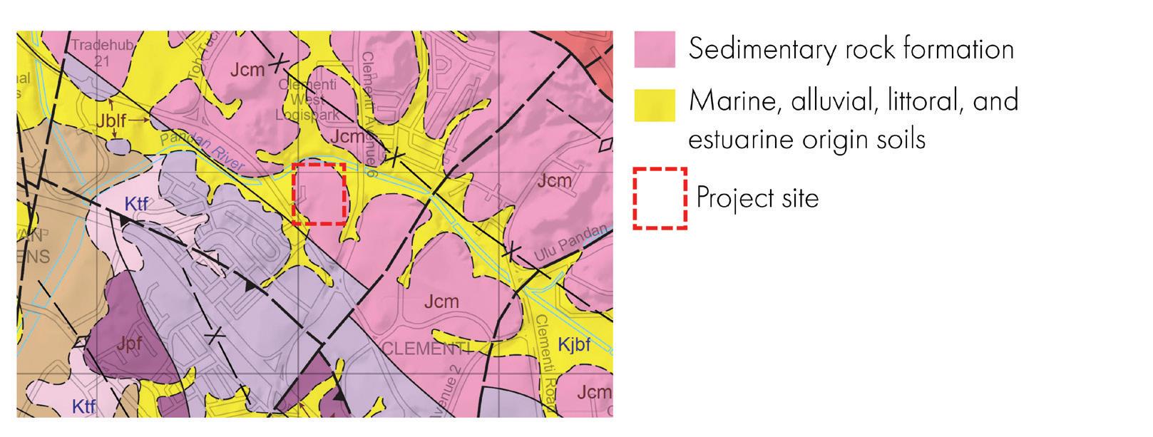
competent ground conditions without site investigations, especially at the site boundary locality. The engineer for the project site used nearby boreholes conducted for the tower block and assumed competent ground when designing the retaining wall. He “did not know” that the presence of soft soils could be encountered so close by.
The agency having jurisdiction required site investigations to be carried out in accordance with codes and standards, including guidance issued by the local engineering fraternity. In addition, the checking of a high slope (more than 6 meters high) subjected to new loadings would require a peer review by an independent geotechnical specialist. However, it appears that these requirements were missed and not complied with during the plan submission and review process.
Before going into detailed site investigation, a preliminary desk study on the geological, hydrogeological, topographical, and historical information can be very useful. For example, differences in ground levels and presence of water bodies may suggest more complicated ground conditions such as the presence of soft deposits in buried valleys and old landslides.
A study of the location of the project site on a geological map (see Figure 3) revealed that at the project site boundary, presence of soft soils is highly probable. Coupled with the presence of an existing low-lying area and river, a cautious engineer would not assume
Many conventional reinforced concrete retaining walls adopt an L-shaped design such that the backfilled earth’s weight on the retained side bearing onto the retaining wall base helps to generate the resistance against sliding and overturning. The bearing pressure at the base of the wall should also be checked to be within allowable limits. If foundation soils are compressible, settlement or tilt could be an issue. Settlement should then be estimated and ensure any movements are still within acceptable limits. Stronger foundations or ground improvement works could be proposed to address the issue.
Another very important aspect is a check on the overall or global stability, i.e combined failure in the ground and in the structural element. This has been mentioned repetitively in codes and guidebooks. For example, the Canadian Foundation Manual stated that “where retaining walls are founded on deep layers or strata of cohesive soils, there is a possibility of failure occurring along a surface passing at some depth below the wall and well behind the backfill. The stability of the soil mass containing the retaining wall should be checked with respect to the most critical potential failure surface. A minimum factor of safety of 1.5 should
be used when designing for overall stability.” Similarly, Eurocode 7 mentions overall stability checks on slopes, near rivers, retaining walls in several separate clauses. In particular, EC7 also reminded readers that “stability problems or creep movements occur primarily in cohesive soil with a sloping ground surface.” The engineer for the project site did not carry out a global stability check, as he felt the “slope was gentle” and the “ground was good” and deemed such a check unnecessary. He was overly focused on designing the retaining wall only for sliding, bearing, and overturning.
Building up a retaining wall from ground surface is likened to adding surcharge on the ground. In this case, a 4-meter-high retaining wall can hardly be considered “light-weight,” as the additional load can be easily 80 kPa.
The presence of soft soils underlying an existing gentle slope would make the slope inherently weaker than it appears to be. This means that, even before any works were started on the slope, the factor of safety could be below code requirements or even close to one, indicating impending failure, as the failure surface would pass through the weakest zone. In this incident, it can be seen that the soft soil had very little resistance against inclined loading (due to the retaining wall surcharge) because at the bottom of the slope, the boundary condition is “unconfined,” i.e. free to move. Compare this to a layer of soft soil deeper underground and loaded vertically where the lateral sides are confined, giving it added resistance. Therefore, an appreciation of factor of safety or capacity of existing slopes can be helpful.
Rain and water have a detrimental effect on slope stability in several ways. Starting from the slope surface, the most obvious is the erosion of soil (washing away at the slope face) and softening of clays when wet causing a decrease in strength and stiffness. The seepage forces inside a soil mass can also cause instability, especially at the slope toe. Saturated soil is heavier than dry soil and this increases the driving force when located near the top of slope. More fundamentally, from an effective stress perspective, an increase in pore pressures causes a decrease in strength leading to lower load-resisting capacity.
Rainfall induced landslides are not uncommon in regions receiving heavy rainfalls. In
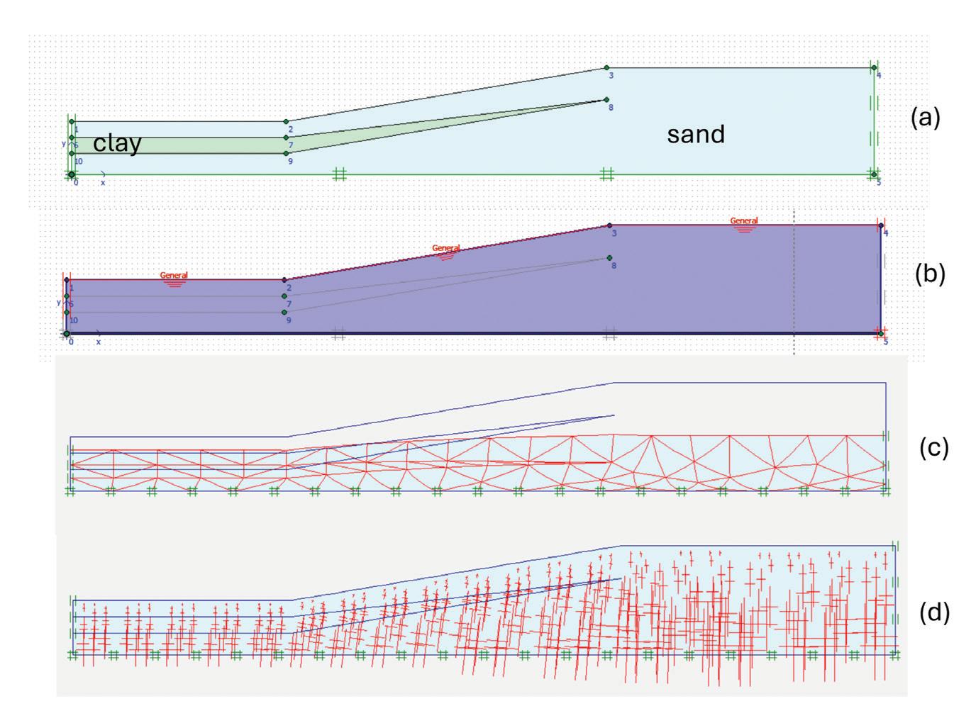
recent years, awareness of climate change has increased dramatically as more and more areas have experienced an increased frequency of returning heavy rainstorms. Prolonged periods of heavy rainfall can cause the development of excess pore water pressure, reducing effective stress and strength. Therefore, it is crucial that engineers adopt the appropriate groundwater levels in slope design, taking into account ground permeability, rainfall, and climate change.
Consider a very simplified representation of the failed slope in a finite element model (Fig. 4) with a slope height of 10 meters and gradient of about 20 degrees. The default model has sand material in dry condition (i.e. no groundwater). The model is then updated with a thin layer of soft clay. Factor of safety are computed for both cases with and without full groundwater (i.e. phreatic level following the slope surface). Results are presented in Figure 5. To capture the initial stresses correctly, a gravity (self-weight) load case was first imposed (Fig. 4c). The artificial deformations generated can be reset to zero at the next stage of loading or analysis, without affecting the stresses generated. A K 0-procedure (coefficient of at-rest lateral earth pressure) computation would not be suitable for non-horizontal surfaces.
Even though the default case has a relatively high factor of safety of 3.84, Figure 5 shows that the factor of safety is reduced by half with the inclusion of full groundwater for both soil with and without the slice of soft clay. With the presence of soft clay, the failure surface is somewhat lowered slightly and forced to pass through the clay layer. When both clay and water are present, the factor of safety dropped to 1.35. Notice how a seemingly safe and “gentle” slope can have a low safety factor.
Many slope failures can be attributed to adverse geological features and groundwater conditions. Figure 6 illustrates two such examples. In the first example, the presence of a shallow impermeable layer (e.g. clay or peat) in relatively permeable (sand) ground creates a perched water table. This shallow perching can cause a rapid and large increase in pore pressures and erosion of material. The piping condition worsens over time as the permeability difference widens. In the second example, a classic soil-rock interface issue shows up in a slope stability problem. The high permeability of the loose sand at the interface again
creates sub-surface erosion when water finds its way into the weakness. The channels or pipes form when a discharge outlet is created at the slope toe with the materials broken loose and carried away.
Post-failure rectification works usually involves strengthening the weak ground. Soft soils are typically treated with ground improvement such as jet-grouting or soil mixing. The insertion of structural elements (such as sheet pile and soil nails) are also effective in enhancing overall slope strength, as the failure surfaces are being cut off or intercepted by much stronger structural elements. To strengthen an existing retaining wall, additional piles can be installed and connected to the retaining wall via tie beams. The wall base can be extended with additional reinforced concrete casting and additional counterforts or buttresses can be introduced. Changing the slope gradient or profile and adding subsoil drains can also be beneficial.
This landslide incident on a gentle slope serves as a reminder of the importance of site investigation, desk study, and checking of overall global stability involving the combined failure of the structural element and the ground. In addition, the understanding and adoption of appropriate groundwater conditions in a slope design is critical, taking into account extreme and prolonged rainstorms due to climate change. Finally, slope engineers need to be aware of the various types of adverse geological features and adverse groundwater conditions and consider the relevance and occurrence of such conditions in their specific projects. ■
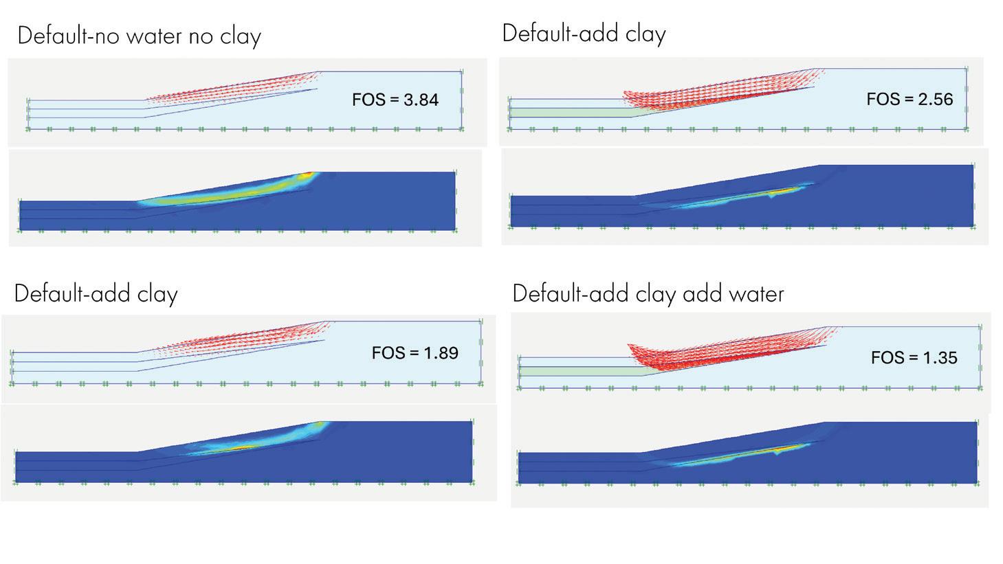
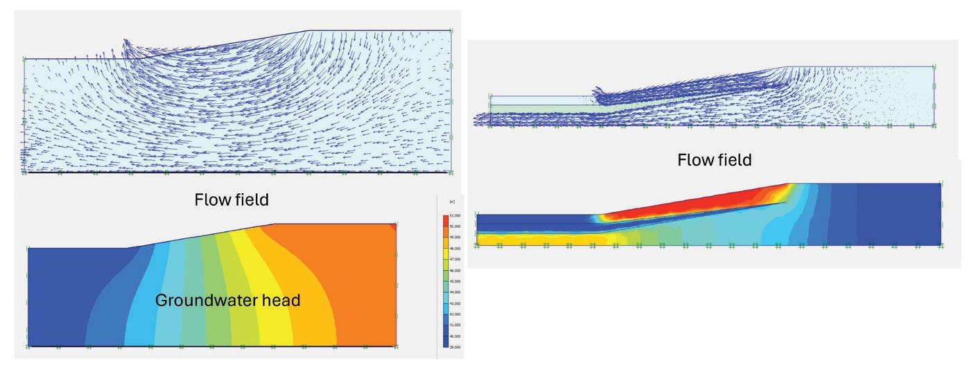
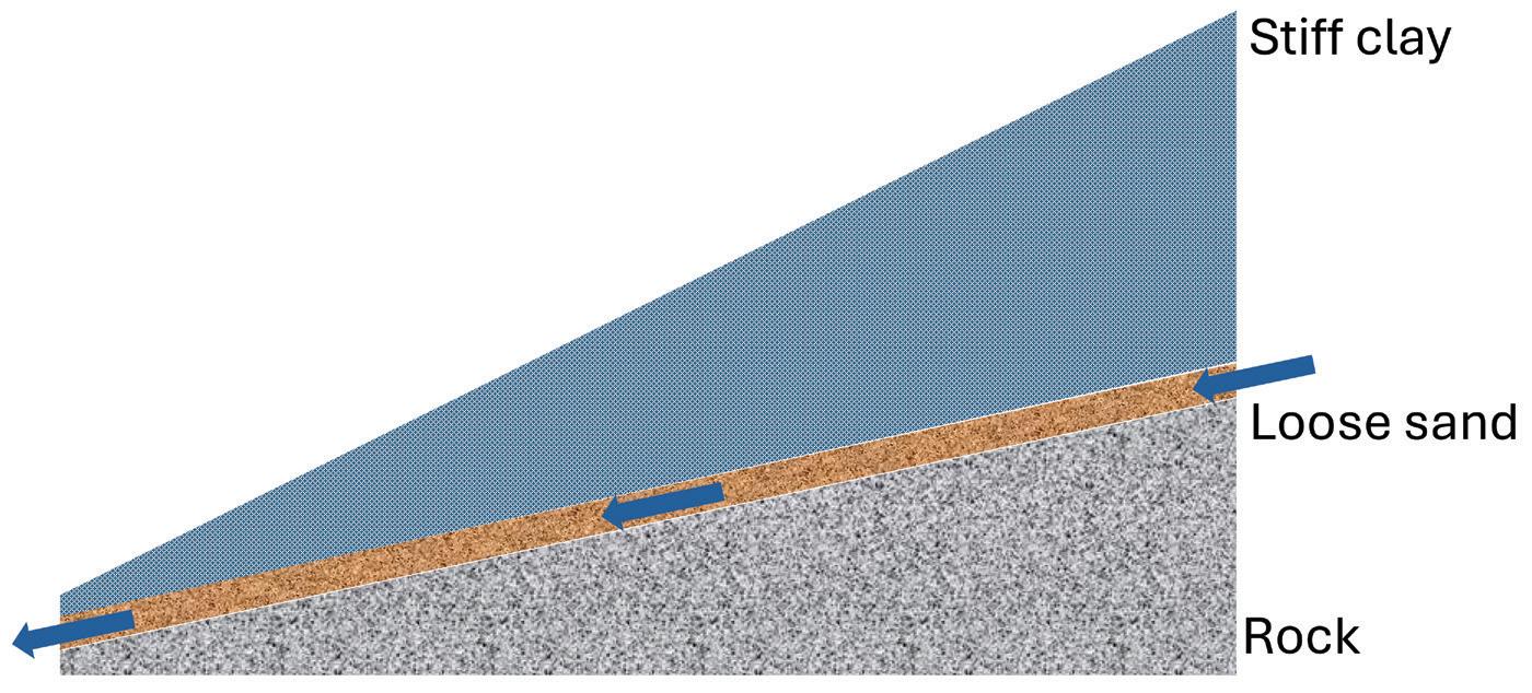
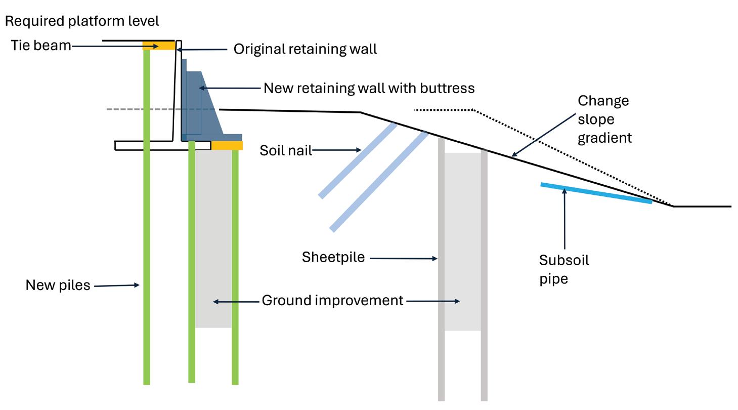
The collapse of the condo in Surfside, Florida, underscores important lessons for the structural engineering community.
By Matthew Fadden, Ph.D, PE, Sedona Iodice, and Gary Klein, PE, SE
The tragic collapse of Champlain Towers South (CTS), which claimed 98 lives on June 24, 2021, in Surfside, Florida, stands as one of the most devastating structural failures in U.S. history. Champlain Towers South was a 12-story reinforced concrete flat plate structure completed in 1981. The building featured 136 units, a lobby-level and basement garage, and a pool deck terrace on the south side. The South Florida Building Code (1979) and ACI 318-77 applied during the design and construction phases.
Witnesses reported hearing loud noises from the building in the hours leading to the collapse. Just after 1:00 AM on June 24, 2021, the collapse initiated. Surveillance footage and early investigations indicated that the initial failure originated in the pool deck slab, which exhibited punching shear failures. These failures triggered a disproportionate and progressive collapse of the eastern portion of the building, which the central core shear walls arrested. The sequence of events underscores how interconnected vulnerabilities in structural systems can rapidly escalate into widespread failures.
Working on behalf of insurers and the court-appointed receivership for CTS’s Condominium Association, Wiss, Janney, Elstner Associates, Inc. (WJE) conducted a comprehensive investigation into the collapse as part of the civil litigation that settled in June of 2022. Our findings shed light on structural design and construction flaws that led to the failure and provide valuable lessons for improving engineering practice.
• James River Insurance Company, WJE client
• Michael Goldberg of Akerman LLP, the insurer and receiver for the CTS Condominium Association.
• The NIST National Construction Safety Team, which is investigating the incident under the National Construction Safety Team Act. NIST provided access to inspect remnants recovered from the collapse and stored in a warehouse.
• Laboratory testing in this article was conducted under a joint testing protocol initially developed by WJE, with funding collectively provided by the parties involved in the litigation.
• WJE experts from London to San Francisco contributed to the investigation.
Our investigation involved multiple stages to identify the causes of the collapse and determine the contributing factors.
Document Review and Analysis. We reviewed numerous documents, including the original drawings, maintenance records, meeting minutes/videos, documentation from other engineers/architects (including the 2018 recertification report and subsequent repair design), and social media data. This information was used to understand CTS’s original design and as-built construction, changes to the structure, and, ultimately, the failure sequence.
Field Investigation. At the collapse site (Fig. 1) and the National Institute of Standards and Technology (NIST) National Construction Safety Team Evidence Facility (Fig. 2 & Fig. 3), we conducted detailed surveys, assessed the condition of structural elements, and investigated the pool deck waterproofing. Concrete, reinforcing steel, and soils were sampled for laboratory testing with the parties involved in the civil litigation.
Laboratory Testing. Concrete and reinforcement samples were tested to evaluate material properties such as steel tensile strength and ductility and concrete compressive strength, carbonation depth, chloride content, and other material characteristics via concrete petrography. Structural Analysis. Based on the understood loading, finite element models of CTS’s tower and the pool deck slabs were developed and used to understand the original structural design and behavior at the time of collapse. These models pinpointed vulnerabilities in the pool deck design, particularly at the slab-column connections. Ultimately, these models offered a clearer picture of how specific deficiencies contributed to the collapse.
We evaluated numerous potential failure theories. Ultimately, what is presented here highlights what we found most relevant.
Almost immediately after gaining access to the collapse site, we commissioned a detailed survey of the basement structural slab (structurally connected to the columns to resist hydraulic groundwater uplift pressures), revealing that the slab elevation varied less than 5.5 inches across the entire structure. No unexpected or large gradients of slab elevation were observed. Geophysical test methods confirmed that voids or karstification were not present. Further, numerous soil borings revealed that the soil was typical to the area with layers of sand and limestone. Based on this, we do not believe that the geotechnical conditions contributed to the collapse of CTS.
We identified significant design and construction flaws and changes to the structure that critically undermined the building’s structural integrity.
The Original Design. The pool deck slab included a topping slab of varying thickness sloped to drain that was not shown on the original structural or architectural drawings but was determined to be original to the structure (Fig. 4). The negative moment region reinforcement (i.e., bars over columns) was specified to have a cover of 0.75 inches. Concrete was specified to have a compressive strength of 4,000 psi. The design live load was 100 psf. No shear reinforcement or drop panels were used. Considering this information and assuming that the design engineer must have known about the topping slab installation, the as-designed punching shear strength was insufficient at nearly all columns supporting the pool deck slab, with demand-to-capacity ratios (DCR) for design up to 1.7 (at column K/13.1) (Table 1). Our structural models of the pool deck slab show that DCRs for flexure in positive and negative moments regions were also insufficient, with DCRs up to 2.0. Simply, the deck design was inappropriate.
As-Built Conditions. Our investigation also found numerous incidences of reinforcement at the top of the slab with excessive cover, reducing the effective depth (d) from 8.125 inches to 7 inches, reducing the critical perimeter for punching (b0), and lowering the shear
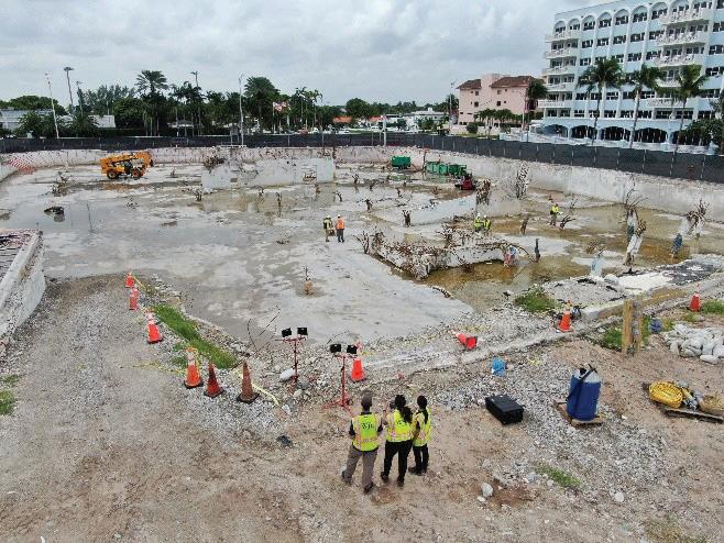
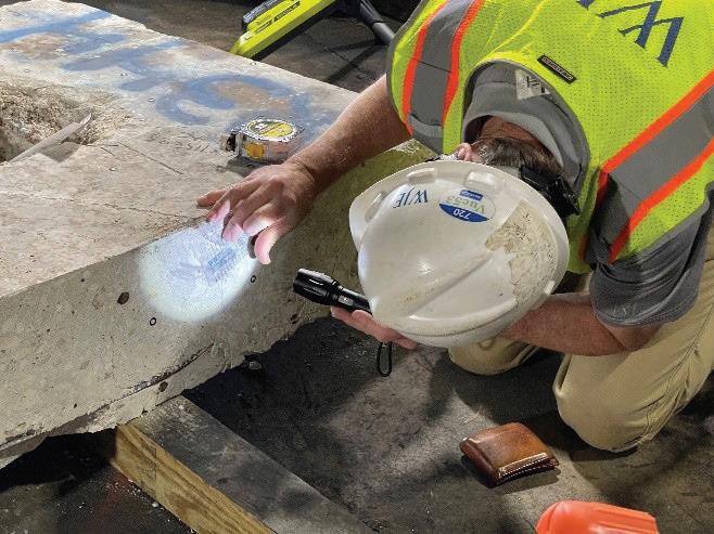
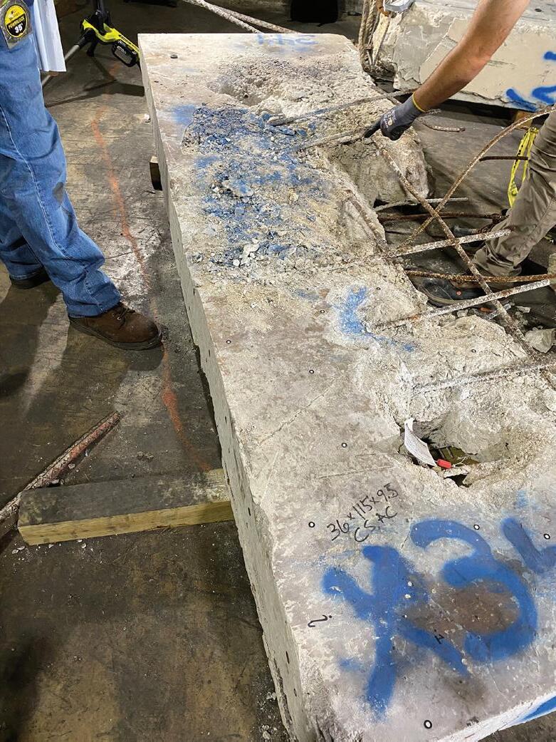
* Does not consider (1) the flexural reinforcement ratio, (2) sustained long-term load, and (3) the effects of the unbalanced moment
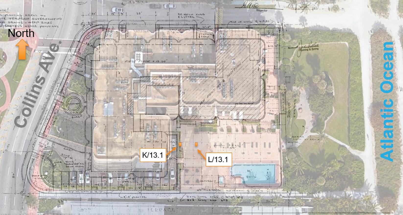
load-carrying capacity based on 4√ƒc'b0d. Further, the low top flexural reinforcement ratio (less than 1%) has resulted in a mechanism known as flexural-induced punching shear. As a result, the stress allowed by ACI 318-77 of 4√ƒc', can be unconservative. Experimental testing has shown this stress to be as low as 2√ƒc'. Reviewing the original drawings and site conditions showed that more planters were on the pool deck than originally designed (it is unclear if the engineer considered them). A 1996 pool deck renovation added further unanticipated loads to the deck, including concrete pavers on a sand bed (4+ inches thick in some locations). However, concrete testing found that the pool deck concrete’s average compressive strength was approximately 4,500 psi. These unanticipated loads significantly increased the load on the slab and contributed to its eventual
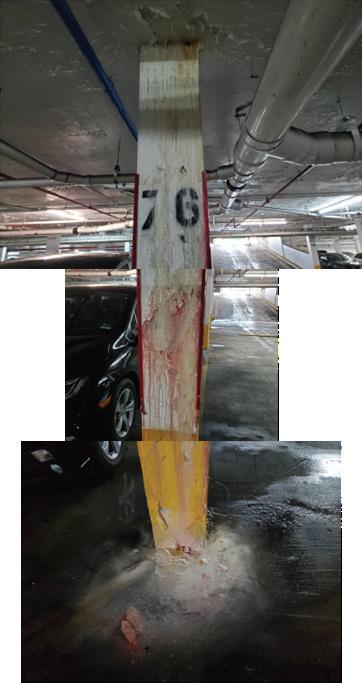
failure. Considering this information and ignoring any ponding water in planters or the pool deck due to poor drainage, the DCR for punching at collapse was approximately 0.85 (no load factors or reductions) (Table 1). The calculated DCR of 0.85 did not consider three important factors: (1) the flexural reinforcement ratio is exceedingly low, which reduces punching shear strength relative to the ACI 318 equation; (2) sustained long-term load reduces punching shear strength compared to normal loading, and (3) the effects of the transfer of unbalanced moment were not included. Quantitative consideration of these effects would result in a DCR substantially exceeding 1.0. In other words, the pool deck has been near its collapse capacity since at least 1996 (when sand and pavers were added).
The Warnings. During our document review, we discovered two sets of photos showing
punching shear and other slab distress present on the pool deck before the collapse of the structure (Fig. 5). Photos from November 12, 2020, 7 months and 11 days before the collapse, show evidence of efflorescence deposits due to water flowing down the face of column L/13.1 (adjacent to K/13.1), indicating that a punching shear-related crack had formed. Photos from June 2, 2021, 22 days before the collapse, show evidence of significant vertical slab movement above column K/13.1 (the most heavily loaded column in the pool deck) and manifesting in the masonry planter walls. An April 13, 2020, photo shows the wall absent this distress. As a result, punching shear-related distress manifested and spread around the slab before the collapse, and the failure mechanism likely took years to develop fully. Ultimately, both L/13.1 and K/13.1 punched through the pool deck slab during the collapse.
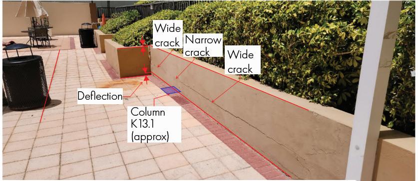
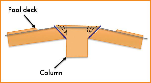
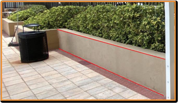
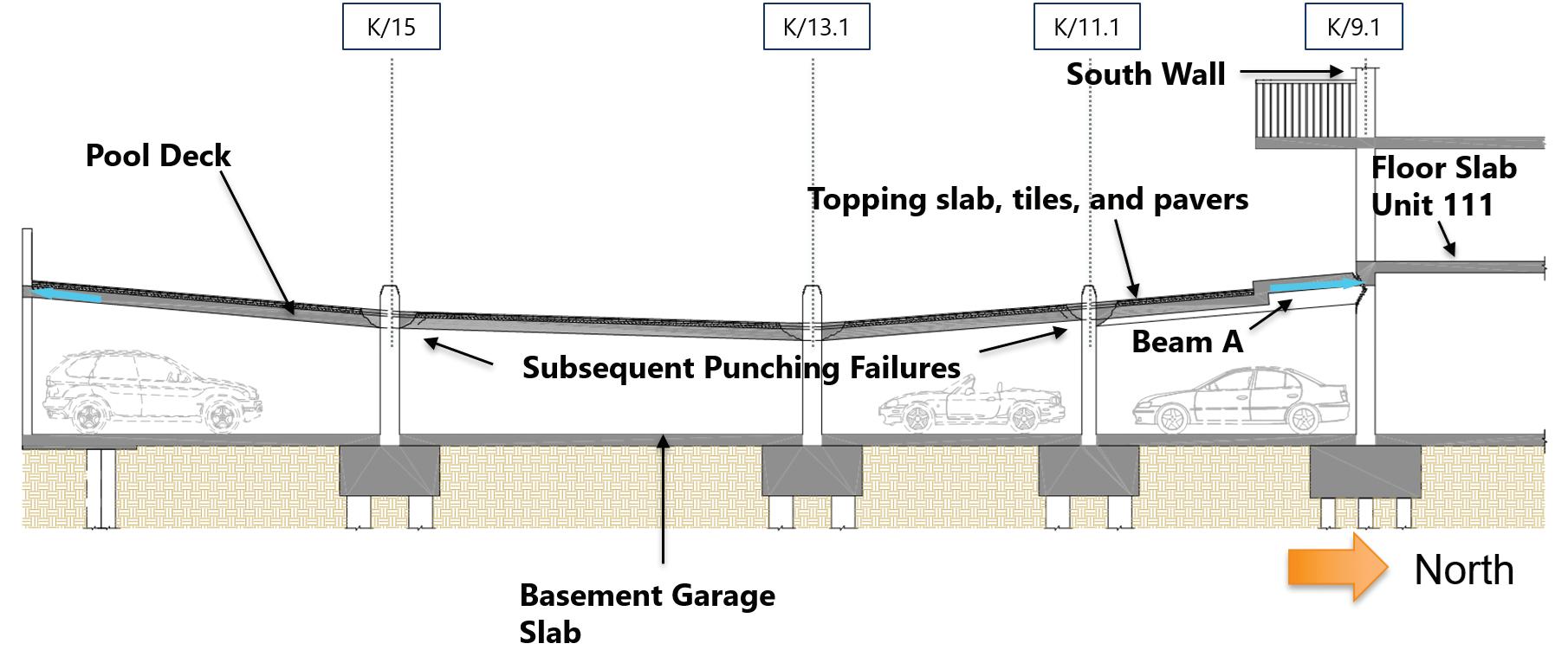
WJE Failure Theory. Our failure theory is based on our understanding of the as-built conditions, structural analysis, videos taken during the collapse and posted on social media, and eyewitness accounts as reported to news outlets. This sequence highlights how localized failures can rapidly escalate into fullscale structural collapses without sufficient redundancy. Our failure theory is outlined as follows:
1. The initial failure occurred when the pool deck to the south of the building collapsed between 1:10 and 1:15 AM. This failure was reported by residents in Unit 111 and others, as well as the security guard. A vacationer at the resort north of CTS captured a video documenting the pool deck collapse on TikTok, noting the noise and the rush of wind from the garage entrance, with visible debris on the garage floor (Fig. 6). Additionally, post-collapse observations of punching shear failures further support this sequence of events.
2. The failure of the pool deck exerted horizontal tension forces on the building’s columns, particularly those on the south face, leading to column failures and significant structural movement (Fig. 7). Horizontal forces, which are typically ignored in beam and slab design, became critical as large displacements occurred.
3. A step in the slab created reinforcement detailing at the building edge that reduced its strength, further compromising the structure.
4. Structural displacements were observed through eyewitness accounts, including reports of cracking walls in Unit 611 and security camera footage from Unit 711 (Fig. 8). These observed displacements ultimately indicate the failure of the columns along the south exterior wall of the east wing, which
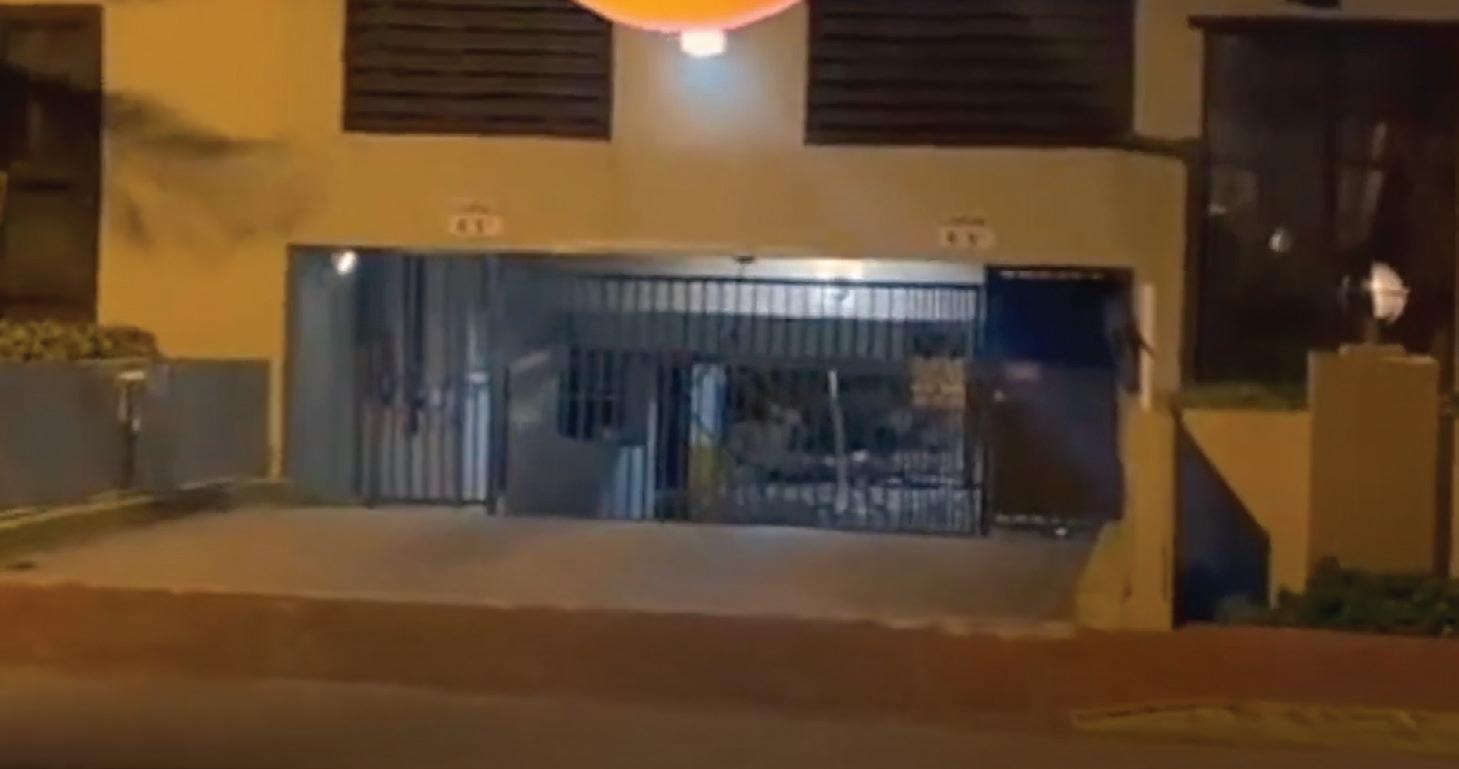
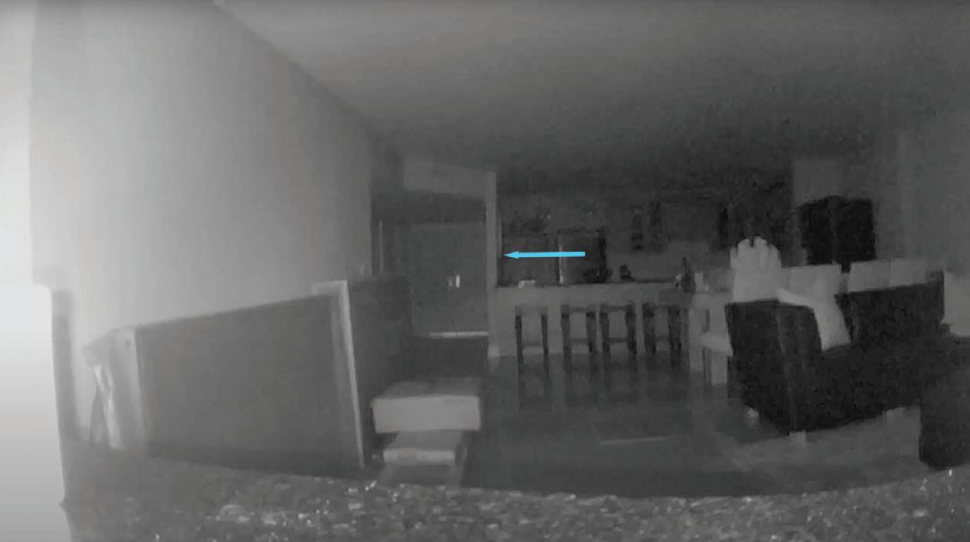
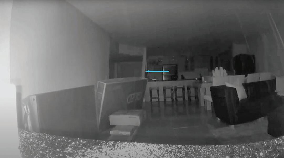
THE 1960 s
Reduce GWP of concrete mix designs using CSA cements
Less GHGs produced per metric ton
Reduced emissions from raw materials
Fewer natural resources consumed
Reduced energy consumption
Meets GSA’s definition of top 20% of low embodied carbon (LEC) cement
EPDs available
about
Cement’s role in lowembodied-carbon concrete.


triggered the progressive collapse of the eastern half of CTS approximately 7 to 12 minutes later, at 1:22 AM.
5. The final collapse was captured by security camera footage from the property south of CTS (Fig 9). Meanwhile, the remaining western portion of the building remained standing due to the presence of the shear wall at the elevator core.
Critical Factors. As shown by our investigation, the failure of the pool deck can be attributed to several critical factors.
1. One of the primary issues was the inadequate design of the pool deck slab, particularly in terms of punching shear capacity. The landscape feature loads on the deck only worsened the issues. It is unclear if the original designers accounted for the topping slab and the additional planters. Furthermore, adding pavers in 1996 placed additional load on the already deficient slab, further exacerbating its structural weaknesses.
2. Additionally, the shallow top reinforcement within the slab reduced the structural section’s effective depth, weakening its overall capacity to resist applied loads. This deficiency made the slab more susceptible to cracking and eventual failure. At the time of design, no integrity reinforcement was required, so the slab’s ability to redistribute load is further reduced (integrity reinforcement was introduced in ACI 318-89).
3. Finally, the visible signs of slab distress documented in columns L/13.1 and K/13.1 were missed and/or never diagnosed. This lack of intervention played a significant role in the ultimate collapse of the structure.
Contributing Factors. Additional factors exacerbated the vulnerability of the building and should be noted.
1. Long-term load effects (i.e., creep) play a significant role in concrete behavior at loads near the failure load.
2. Water buildup on the deck and in the planters was likely present due to the repeated repairs to the planters and the inadequate
drainage at the pool deck. However, we do not know the amount of water present at the time of collapse.
3. Finally, while corrosion was present in some areas, its significance remains unclear. We saw only limited corrosion during our investigation.
Regardless, the structural design, construction, and added load were the primary causes of the collapse.
The tragic collapse of CTS underscores important lessons for the structural engineering community. A thorough review of the failure highlights key areas where improvements in design, construction, and inspection protocols could prevent similar disasters in the future.
Importance
and Appropriate Design. The collapse demonstrated the consequences of inadequate punching shear capacity in the pool deck slab. The failure of a structural component triggered a progressive collapse, emphasizing the need for structural redundancy to prevent disproportionate failures. Thankfully, nearly all buildings are structurally safe, and those constructed after ACI 318-89 adoption include integrity reinforcement. More recently, ACI 318-19 adopted changes to attempt to prevent the formation of flexuralinduced punching failures. Appropriately designed and constructed flat plate slabs are both safe and economical. Furthermore, plan reviews and special inspections, which are increasingly common, can potentially catch design and construction errors.
Recognizing the Impact of Unanticipated Loads. The failure of the pool deck slab was exacerbated by excessive loading beyond its original design capacity. The best practice for engineers is to carefully evaluate any modifications or renovations that could impose additional loads on existing structures. Proper documentation and thorough structural assessments should happen before significant changes occur.
Effective Inspection Protocols. Visible signs of distress, including efflorescence deposits, cracking, and vertical slab displacement, were documented in the months leading up to the collapse. These warnings were either missed, misdiagnosed, or not acted upon in time at CTS. Recent examples of severe punching shear strength deficiencies discovered after analyses and testing include the Riverview Condominium in Cambridge, MA, and the Dockside Condominium in Charleston, SC.

In both cases, the buildings were evacuated. Regardless, there are countless other examples of punching shear strengthening retrofits after identification, analysis, and testing. If significant visible signs of distress are noted in flat plate construction, structural review of punching shear strength based on non-destructive assessment of as-built conditions is prudent. Engineers and building owners should be vigilant concerning newly forming distress. In Florida, a new milestone inspection law has been passed mandating the inspection of many condominiums (SB-4 and SB-154). Nevertheless, engineers and the general public should understand that no inspection can guarantee the structural performance of a building.
Continued Research. The tragedy caused by the CTS collapse highlights the need for additional structural engineering research. Punching shear-related research should consider the effects of time and environmental factors on punching shear capacity. The CTS
failure propagated rapidly, demonstrating the disproportionate impact of localized failures. Research should explore improved progressive collapse models and structural retrofitting methods to improve redundancy and failure resistance. Finally, the structural engineering community should develop strategies to better communicate with the public regarding structural integrity and the potential risks for their existing infrastructure.
This tragedy is a stark reminder of the need for effective design standards (including plan review and special inspections) and timely intervention to address structural concerns. By applying the lessons learned from this disaster, the structural engineering community can build safer, more resilient structures—ensuring that past failures drive future innovation rather than repeat mistakes. ■
Matthew Fadden, Ph.D, PE, is Associate Principal, Wiss, Janney, Elstner Associates, Inc., Ft. Lauderdale, FL, specializing in failure investigations, structural analysis, and repair design. His work includes high-profile failure investigations, such as the Champlain Towers South collapse, advanced finite element modeling and structural testing for evaluating reinforced concrete and steel structures. Fadden serves on AISC’s Committee on Specifications Task Committee 4 Member Design.
Sedona Iodice, EI, is an Associate III at Wiss, Janney, Elstner Associates, Inc. (WJE). She holds a BS and ME degree in Civil Engineering from the University of Florida. Ms. Iodice joined WJE in 2022 and has contributed to numerous structural investigations and repairs.
Gary J. Klein, PE, SE, is Executive Vice President and Senior Principal at Wiss, Janney, Elstner Associates (WJE). His work includes high-profile collapse investigations (Hyatt Regency Walkway, Koror-Babeldaob Bridge) and extensive research in concrete structures and volume change movements. Klein is a member of the National Academy of Engineering and the ACI 318 main committee, has served on the NIST National Construction Safety Team Advisory Committee, and received the University of Illinois Distinguished Alumni Award for his contributions to structural engineering.
Developing code provisions for a class of buildings that are relatively similar is difficult. A better approach is to define the problem, present information on past building performance during earthquakes, and then let the structural engineer decide on the appropriate design.
By John Dal Pino
Concrete tilt-up buildings were originally observed as requiring attention based on their poor performance in the 1971 San Fernando earthquake. For many buildings, either the exterior walls fell away from roofs and/or their roofs pulled apart internally leading to roof collapse, allowing the exterior walls to then fall or lean outward precariously. This was the result of roof to wall lateral force connections relying on cross-grain bending of the wood ledgers and the lack of internal cross-ties in the roof diaphragm.
It may come as a surprise to many engineers, but prior to 1971, there were no specific provisions for the design of tilt-up buildings in the building code since the structures did not fit neatly into any of the listed building systems. Tilt-ups weren’t concrete buildings, and they weren’t wood buildings either. And dynamically they don’t perform like any other building, then or now, but this was not recognized for many years. In some ways, the original concrete tilt-ups were like the original brick bearing wall buildings, with modern concrete instead of archaic brick.
For those unfamiliar with original concrete tilt-ups, they were typically constructed with:
• Concrete perimeter walls (5 to 6 inches thick).
• 1/2-inch-thick plywood roof sheathing.
• 2X4 wood sub-purlins spanning 8 feet to purlins.
• 4x14 wood purlins spanning 24 feet to girders.
• Glu-laminated timber girders (various spans).
• Steel columns.
Following the 1971 San Fernando earthquake, the design provisions for tilt-ups in the Uniform Building Code were changed on several occasions during the following decades, in a manner that some engineers have characterized as “trial and error.” The changes to the code mainly focused on the prescriptive out-of-plane wall anchorage forces. The required force coefficients were incrementally increased for 0.2g to 0.3g in the 1979 UBC, to 0.45g in the 1991 UBC (but only in the center of the diaphragm span) and to 0.63g in the 1997 UBC (now over the full diaphragm width) over a period of around 25 years. See Figure 1 for a graphical representation of the changes.
This incremental “trial and error” approach could have been avoided, in my opinion, had engineers spent more time assessing how concrete tilt-ups and their cousins—concrete masonry wall buildings—actually respond dynamically in earthquakes rather than attempting to develop prescriptive solutions that addressed observed performance in the last earthquake rather than the cause. Each time, these code changes were thought to have solved the problem until the next large earthquake occurred, and the code was found lacking again. Then the process was repeated. The performance in the 1994 Northridge earthquake showed that the code changes made over the previous two
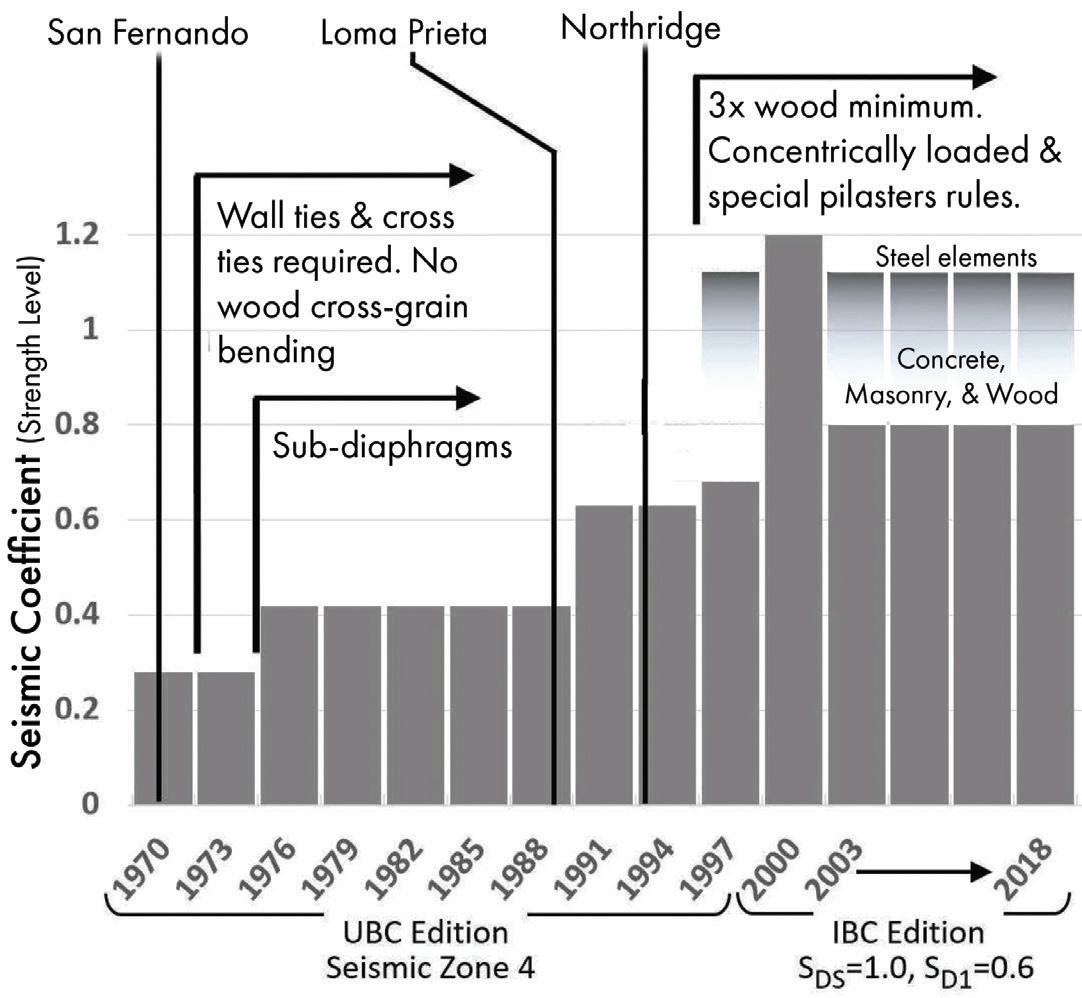
decades had not gotten to the root of the problem, as shown in Figure 2. The building was a modern structure with out-of-plane connection hardware (using holdowns) (Fig. 3).
Many cities in California have enacted their own retrofit ordinances, but somewhat surprisingly, given the large number of such structures throughout California, there is no statewide retrofit ordinance. The retrofit ordinances tended to focus on the early versions of these buildings which posed the greatest hazards, those designed using the 1976 UBC or earlier editions. The City of Fremont was an earlier adopter and enacted a retrofit ordinance titled Earthquake Hazard Reduction in Existing Tilt-up Concrete and Reinforced Masonry (TRM) Buildings. The ordinance required retrofit in accordance with 1997 Uniform Code for Building Conservation (UCBC), used for existing structures, which specifies lateral forces equal to 75% of the 1997 UBC provisions for new buildings. As the name of the ordinance suggests, the intent is hazard reduction.
The retrofit of tilt-ups is a quite straightforward affair, often done in two phases. The first phase involves adding or increasing the strength of the out-of-plane wall anchors and creating diaphragm cross-ties using off-the-shelf holdown anchors. Two carpenters on a scissor
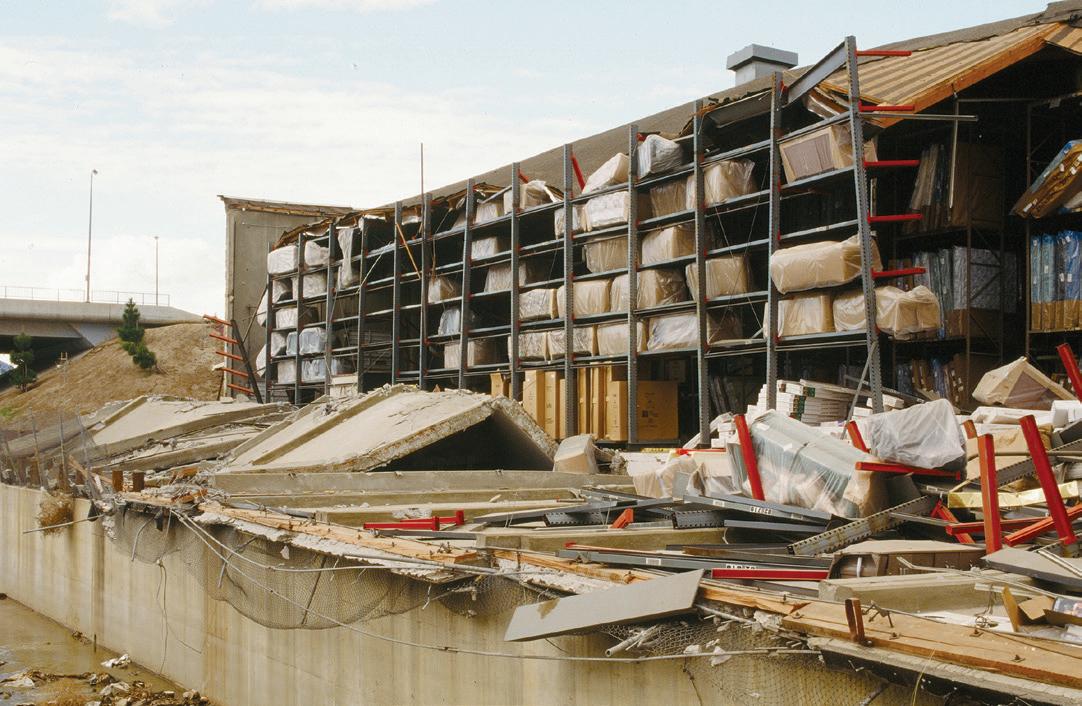
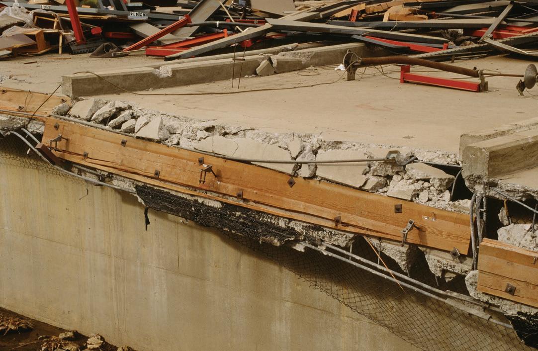
lift with a drill can accomplish the task. The second phase involves improvement to the diaphragm nailing. This work is usually put off until the next re-roofing project when the cost of additional nailing is small as a percentage of the entire project.
In a July/August 2003 STRUCTURE article by Dave McCormick of Simpson Gumpertz & Heger (SGH), Seismic Retrofit – Strengthening Tilt-up Structures, the authors state, “Along with unreinforced masonry buildings, older wood frame buildings with parking below, and older concrete frame buildings, older tilt-ups have proven to be among the worst performing building types in an earthquake.”
The Structural Engineers Association of California (SEAOC) developed two documents that can be used by engineers to reduce the vulnerabilities in existing tilt-ups: Guidelines for Seismic Evaluation and Rehabilitation of Tilt-up Buildings (Guidelines), and Chapter 2 of Guidelines for Seismic Retrofit of Existing Buildings (GSREB). The GSREB is an appendix to the 2003 International Existing Building Code. Both the GSREB and the Guidelines are based on extensive research, by SEAOC members, of tilt-ups in past earthquakes including the 1994 Northridge earthquake.
It can be argued (some would say with considerable hindsight) that the key to understanding the seismic performance of tilt-ups is to focus almost entirely on the roof diaphragm and the strength of the connections between the roof and the walls and within the roof itself since these components constitute the “system” that responds dynamically to an earthquake. Even today there is no designated structural system for tilt-ups with an appropriate R value. Tilt-ups are still characterized as concrete or masonry bearing wall buildings with the diaphragms designed for the same R and out-of-plane anchorage forces specified in a separate section. Some advancements have been included in ASCE 7-22, Chapter 12, Section 12.10.4 which contains provisions for roof diaphragm design. They are still too prescriptive to me.
What is still overlooked is that the wall panels, the foundations, and the connections of the wall panels to the foundations are essentially rigid and non-yielding, and regardless of the actual wall design details, are almost never the cause of poor seismic performance.
Dynamically, the wood roof diaphragm and the tributary out-of-plane mass from the concrete walls perpendicular to the earthquake load form a single degree of freedom system: essentially a weighted, simple span beam spanning between two reaction points (the walls parallel to the assumed EQ direction). The reaction points (the parallel walls) have far more strength than the force that the roof diaphragm can generate, so the roof diaphragm is where any yielding will occur. The roof diaphragm is the “yielding” element and the connections between the roof
and the walls and the walls themselves are the “non-yielding” elements.
Thinking back to structural dynamics, it only takes about 10 cycles of input for “things to blow up” when the frequency of input matches the natural period/frequency (resonance) of the structure even if the input demands are not that great. This is what happens with tilt-ups. The key to proper seismic performance is determining the actual strength of the roof, usually controlled by the diaphragm shear strength based on the provided plywood nailing and then designing the wall to roof connections for that load or greater with an appropriate R-factor, rather than a code-based out-of-plane load. Using more nails in the roof diaphragm than required, either by design or unintentionally by the contractor (isn’t more, better than less?) is a bad thing.
The required out-of-plane force is:
w (force per foot) = shear strength of diaphragm * length of diaphragm in direction of the load *2 / width of the diaphragm perpendicular to the load
This is an average force assuming a uniform acceleration across the length of the diaphragm. One could also assume that the acceleration shape is more of a bell curve, with higher accelerations in the center region of the diaphragm.
Once in this performance-based mindset, the designer will quickly realize that the out-of-plane connection loads will be highest in the longitudinal direction of a building. This is counterintuitive to many engineers. Minimum shear nail spacing of six inches on center in the longitudinal direction for a long building typically creates a diaphragm that is much, much stronger than it needs to be based on prescriptive code design provisions. Since something will fail, the out-of-plane connections becomes the weak link.
Those particularly interested in this topic should also review FEMA P-1026, Seismic Design of Rigid Wall-Flexible Diaphragm Buildings – An Alternative Procedure (Second Edition)
The key to proper seismic performance is determining the actual strength of the roof, usually controlled by the diaphragm shear strength based on the provided plywood nailing and then designing the wall to roof connections for that load or greater with an appropriate R-factor, rather than a code-based out-of-plane load.
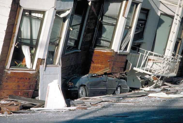
The 1989 Loma Prieta and 1994 Northridge earthquakes showed that “vintage” buildings with large open parking areas on the ground level or open areas in crawl spaces have significant seismic vulnerabilities and are prone to collapse in strong earthquake shaking. Many were designed before the advent of building codes, but many are more modern buildings with tuck-under parking, code-compliant at the time of their design. Figures 4 and 5 show damaged buildings in the Marina District of San Francsico after the 1989 Loma Prieta earthquake. Common design flaws include:
• The bottom story has significantly less lateral strength than the stories above.
• The floor diaphragm above the bottom story lacks sufficient strength to transfer the forces from the story above to the lateral force resisting elements.
• The bottom story has a torsional irregularity due to offset of shear walls (from the center of gravity) to create space for parking.
• The stiffness and strength of floor diaphragm above the bottom story is insufficient in resolving the torsion.
In addition, these buildings are mostly older structures that were designed to lower lateral forces levels than today, sometimes with straight sheathed walls or stucco clad stud walls without underlying sheathing (straight, diagonal or plywood).
In 2013, nearly 25 years after the 1989 Loma Prieta earthquake, the City of San Francisco embarked on an ambitious and groundbreaking endeavor: the mandatory seismic retrofit of its wood framed soft-story apartment buildings. The Loma Prieta earthquake caused considerable damage to such buildings in the Marina District and exposed the vulnerability of buildings with soft and weak first stories. Similar performance occurred in the 1994 Northridge earthquake. Yes, even wood framed buildings, thought by most engineers to be the most naturally earthquake resistant type of structure due to their lightweight nature and reserve strength, can collapse under the right (or perhaps wrong) circumstances. According to a 2016 report by the Association of Bay Area Governments, San Francisco had 6,700 soft-story buildings, far more than the rest of the region combined. The goal of the San Francisco Ordinance was two-fold: 1) address an obvious structural hazard with a threat to life-safety and 2) protect the city’s housing stock by improving resilience. Approximately 10% to 15% of the San Francisco population live in roughly 5,000 buildings covered by the ordinance. Since the enactment of the San Francisco Ordinance, Los Angeles, and Oakland have enacted similar ordinances.
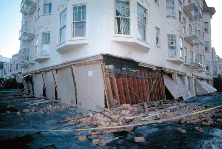
San Francisco, despite its downtown of steel and concrete highrises, is really the land of wood structures—long, narrow, multi-story buildings with zero side setbacks. Whether in single family homes or multi-tenant apartment buildings, parking on the ground level is almost universally nose-to-tail. Most of the oldest buildings, built before the automobile era, have been modified to allow for parking too. Linear parking configurations make transverse shear walls impossible to use and the result was thousands of weak and soft story buildings.
The Mandatory Seismic Retrofit Program addresses wood framed buildings three-stories or taller, or two-story buildings over a basement or crawl space, with five or more dwelling units, constructed under a permit dated before January 1, 1978, and with no prior seismic strengthening. Buildings were grouped into four Tiers, with the largest and most vulnerable in Tier 1 (special, institutional, and educational), then Tier 2 (15 or more units), then Tier 3 (5 to 14 units) and then Tier 4 (buildings with ground floor commercial spaces). Commercial buildings were placed last because it was judged (as it turned out rightly) that building owners would need additional time to plan and work with tenants. It turned out that businesses often had to close for several months or moved to other buildings to stay in business.
The Ordinance requires retrofit work in the weak/soft or “target” story only. The target story is considered weak/soft if the number of walls and the wall layout are significantly different from the typical stories above. San Francisco’s residential buildings commonly have identical or nearly identical plan layouts in the upper stories with a large number of interior walls around small rooms, and open ground levels consisting of undeveloped crawl spaces or developed ground levels with large unobstructed areas used for parking or storage. To be subject to the Ordinance, the lateral force resisting system in the target story must be wood framed elements.
Most retrofits involve the addition of plywood sheathing to the existing wood stud walls. When this is not feasible (due to parking or access requirements) steel moment-resting frames are often added in the parking stalls either in front of or behind the existing columns (Fig. 6). The size of frame elements can impact parking (this is the prime driver of any design) so having more frames means smaller columns and less demand on the existing structure (more attachment points). The frames can be of a traditional configuration or inverted, with the beams in the ground and the columns cantilevering upward
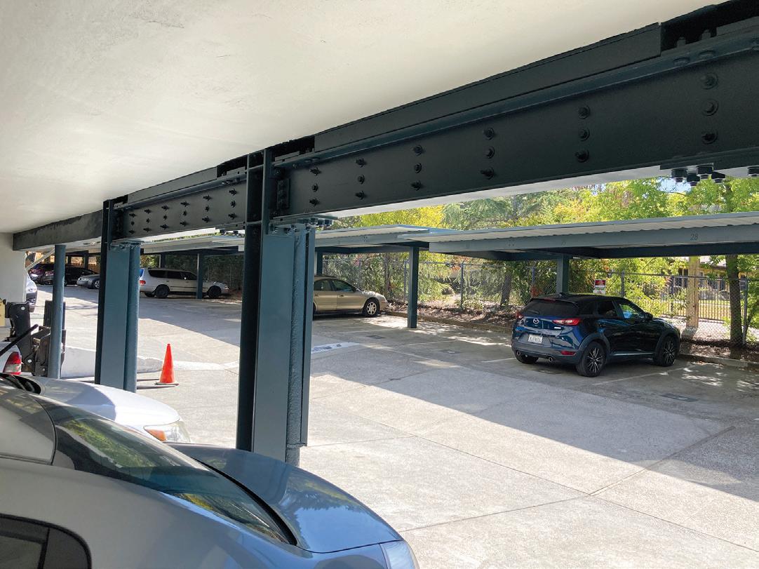
to the floor above (Figs. 7 and 8). Whenever possible, plywood shear walls or high capacity “strong walls” manufactured by Simpson and Mi-Tek are often used instead of steel moment frames to save money. Over time, as retrofits were designed and constructed, it became evident that the technical requirements were not as clear as originally hoped, which led to a problem with the consistency in the application of the program’s technical provisions. San Francisco looked to the Existing Building Committee of the Structural Engineers Association of Northern California (SEAONC) for guidance, which improved the situation but did not eliminate all inconsistencies.
• How Strong? —California Existing Building Code (CEBC), Appendix 4, allows retrofits to be designed to 75% of the design base shear coefficient used for new buildings which is based on the 475-year earthquake (i.e. repeat of the 1906 Earthquake). Engineers found that the strength of the stories above the target story, due to the considerable length of interior wood lath and plaster finishes and exterior wood siding, sometimes also with
stucco, in older buildings, often had lateral strengths far in excess of the base shear required as a result of their weight alone. As a result, designing to the code design base shear improved the expected performance but is considered by many engineers to be insufficient to eliminate the soft- or weak-story condition.
• Multiple R-Values—Retrofits often involved multiple systems with different R-values. Plywood shear walls are almost always used (R=6.5) but due to the parking issues, ordinary steel moment frames (R=3.5) and cantilevered column systems (R=2.5) are often used. After much debate, R values could be considered on a line-by-line basis, largely because of the assumption of flexible diaphragms.
• Foundations—Original continuous footings below the wood bearing walls are commonly of unreinforced concrete. In the oldest buildings, some footings are of brick, predating concrete. Although there was no consensus, standard practice was to not replace or strengthen the foundations unless there was a large overturning moment that the existing foundations could not resist. Providing new foundations to resist overturning moments or to address ACI anchor bolt provisions would increase construction costs astronomically and were judged to not significantly improve the expected performance relative to the extra cost.
As one can see, developing code provisions for a class of buildings that are relatively similar is difficult. It is far better to define the problem, present information on how such buildings have performed in past earthquakes and why, and then let the structural engineer decide on the appropriate design. There is still an important role for plan review by the building department to confirm that a proper design has been developed and constructed. ■
Part 2 of this series appeared in the March 2025 issue of STRUCTURE.
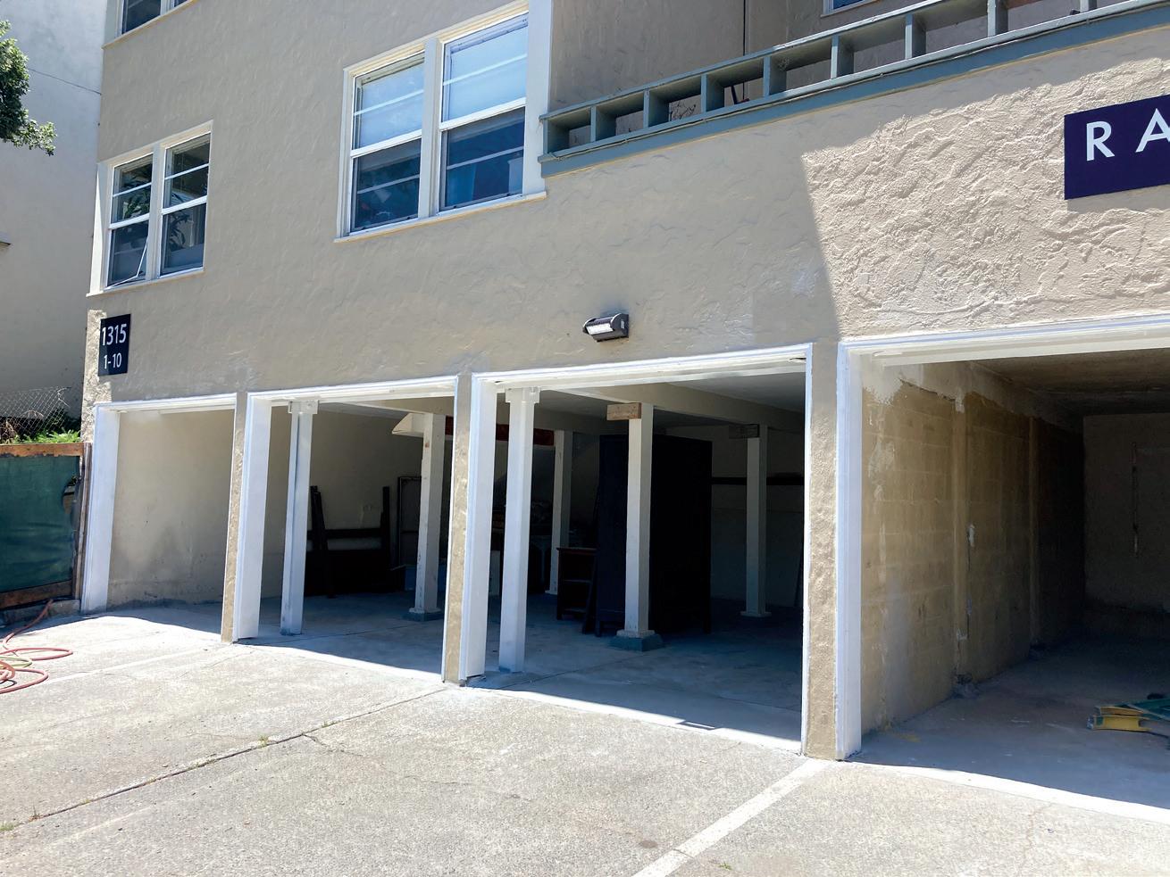
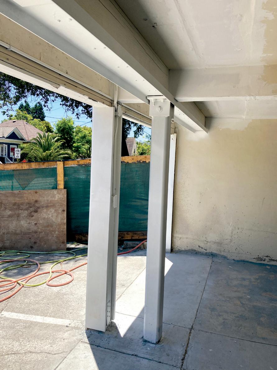
Risk management strategies, innovative technologies, and stakeholder engagement together can lead to structures that are better able to withstand disruptive events.
By Dr. Aamir Butt, PE
Infrastructure resilience refers to the ability of systems and communities to withstand and recover from disruptive events while maintaining essential functions. It encompasses robustness, adaptability, and preparedness in the face of challenges such as natural or man-caused disasters, cyber threats, or societal changes. Resilient infrastructure not only ensures the continuity of critical services like shelter, transportation, energy, and communication but also enhances overall community stability and economic vitality. By integrating risk management strategies, innovative technologies, and stakeholder engagement in design, construction, and operation, infrastructure resilience strengthens our capacity to thrive in a dynamic and interconnected world.
Conversely, the cost of inaction can be staggering, leading to increased vulnerability, economic losses, and compromised community wellbeing. By prioritizing resilience within the project execution and asset management protocols, structural engineers can prevent systemic breakdown and mitigate the consequences of unforeseen challenges, fostering long-term sustainability and prosperity.
Construction projects are capital-intensive endeavors and require continuous input by many parties with diverse expertise, roles, and responsibilities. Successful project execution demands a thorough understanding of technical aspects, managerial skill set, and informed consensus among all involved. Catastrophic failures during construc tion often indicate a lack of understanding, communication, and coordination between owners, design consultants, contractors, and regulatory agencies. They point to a disregard of expert advice, pro motion of unrealistic expectations, absence of accountability, and failure to report issues. They also suggest that the project team is experiencing fundamental weaknesses in its organization, operation, or management, requiring comprehensive interventions to restore functionality and stability. Overall, it leads to a situation where the project organization fails to operate effectively, resulting in a systemic breakdown, causing loss of control and widespread disruption. On the other hand, notwithstanding extreme weather events or external human-caused interference, catastrophic collapse of a facility during operation is most likely the result of poor asset management. It helps to recognize that although failure of any engineering system can be problematic, it is the structural failure which is usually the most devastating due to its high potential to cause loss of life. Other systems, if not functioning properly, can be isolated or switched off for repair or replacement, but the structural system has no such inherent isolation or shut-off mechanism. A structure must function
as intended every time, all the time! This recognition is essential for acknowledging that structural integrity is imperative to maintain asset resilience. From an asset management perspective, whether it is due to hesitation, indecision, or lack of awareness, failing to take prompt action has dire consequences, and often the cost can remain hidden until the consequences become devastatingly clear.
On March 15, 2018, a pedestrian bridge under construction at Florida International University (FIU) in Miami collapsed onto a busy street, resulting in six fatalities and multiple injuries. This bridge, designed to ensure pedestrian safety across a bustling road, had been installed just five days before the tragic incident. Investigations revealed that cracks had formed in the bridge's structure before it fell, highlighting potential structural problems. Despite these warning signs, no measures were taken to reinforce the bridge or close the street. Federal investigators attributed the collapse to calculation errors by engineers, as detailed in a report by the National Transportation Safety Board. The report also indicated that an independent peer review consultant failed to detect the Engineer of Record's (EOR) load and capacity calculation mistakes. Moreover, the EOR did not recognize the significance of
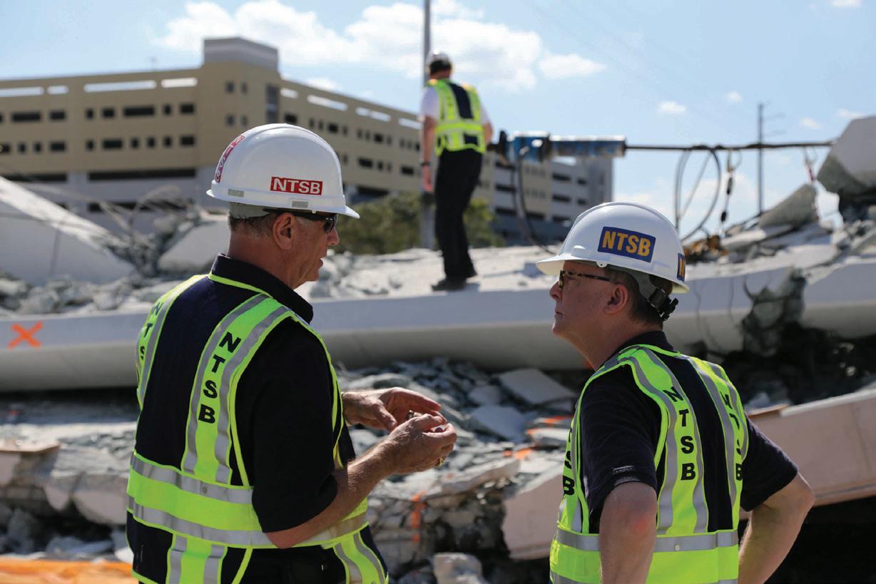
the structural cracks observed before the collapse and failed to seek an independent peer review for a remedial plan. Investigators believe that the responsible parties should have closed the street to ensure public safety and that the state's DOT should have halted the bridgework when the structural cracks became severe.
Since 2018, numerous other facility collapses have occurred including the Champlain Towers South condominium complex near Miami, Florida; an apartment building in Davenport, Iowa; a parking garage in New York City, New York; and the First Church of Christ in New London, Connecticut, with the last one occurring in January 2024.
These cases highlight critical systemic failures due to neglect, lack of accountability, and gaps in regulatory oversight across multiple aspects of design, construction, site supervision, and operation. Addressing these shortcomings through better engineering, monitoring, and governance could have improved resilience of the built environment, protecting lives and resources.
Systemic breakdown can be averted by improving an asset’s resilience so it can absorb, adapt to, and recover from disruptions. This requires that the asset is planned, designed, constructed, occupied, and operated to meet modern demands and challenges, ultimately contributing to a safer, more efficient, and sustainable built environment.
In case of the FIU Pedestrian Bridge collapse, the potential for systemic breakdown could have been eliminated, or at least minimized, by establishing, executing, monitoring, and tracking robust processes, elements, and functions, during planning, design, and construction phases. Technical and constructability reviews during planning and design stages provide opportunities to catch errors, omissions, and oversights detrimental to the asset. These phases also allow for consideration of likely risks and lead to the development of risk management and contingency plans. Following groundbreaking, construction projects can encounter unforeseen issues such as faulty material or equipment, material and labor shortages, inclement weather conditions, or on-site changes. Establishing and following robust counter measures prior to construction allows for better management of these scenarios during construction, and enhances the ability to adapt safely, quickly, and efficiently.
Since 2018, several building collapses have occurred while the facilities were already occupied and operational. This presents a different set of challenges to be addressed. Built assets must maintain a comfortable and functional environment for end users despite adverse events. This is a function of safety, security, occupant protection, and effective operations. Although all building systems including architectural, MEP, life safety etc. contribute to a facility’s operability, they depend on a robust structural system to function optimally and to maintain their effectiveness during extreme conditions. Because of this, integrity of structural systems is a vital component for sustaining the building’s ability to continue serving its intended purpose.
It is also important to recognize that the failure of other systems, such as an electrical fire or corrosion due to lack of proper waterproofing, may weaken a structure. Therefore, regular maintenance, routine
Humans have always sought to create infrastructure and settlements that could withstand natural disasters, adapt to environmental changes, and support the long-term sustainability of communities.
inspections, and conformance to updated codes and standards are essential for all architectural and engineering systems to maintain asset resilience.
1. Regular Maintenance: Built assets are exposed to various environmental factors, such as moisture, temperature fluctuations, and pollutants, which can cause deterioration. Identification and repair of minor issues is imperative to ensure they do not become major problems. Regular maintenance is often more cost-effective than major repairs or replacements. By investing in maintenance, owners can avoid the high costs associated with emergency repairs or complete failures.
2. Routine Inspections: Inspections can uncover damage that might not be immediately visible but could compromise building systems in the long run. This includes issues like site erosion, foundational settling, corrosion, or hidden damage due to extreme weather events.
3. Codes & Standards: Building codes and safety standards evolve over time. Compliance with updated codes and standards ensures that the facility conforms to regulatory requirements.
While the terminology of "resilience" may have gained prominence in modern discourse, the concept has been integral to human civilization for centuries. The tools and technologies have evolved, but humans have always sought to create infrastructure and settlements that could withstand natural disasters, adapt to environmental changes, and support the long-term sustainability of communities.
Disregarding resilience in the built environment poses complex challenges and has severe repercussions. Beyond the tragic loss of life, asset failures undermine trust in the industry, damage relationships, and squander opportunities. To prevent a negative outcome in modern construction and asset management sectors, business executives and project managers must consider the core principals of resilience, place safety at the highest level in the hierarchy of business decisions—and adhere to ethical leadership, regulatory oversight, established processes, and a commitment to transparency and quality. ■
Full references are included in the online version of the article at STRUCTUREmag.org .
Dr. Aamir Butt, PE, is a Senior Principal with STV and brings diverse experience with leading global design, construction and asset management organizations. His expertise include overall program management encompassing planning, pre-construction, design management, procurement and construction management on national and international capital programs/projects.
A new, free database provides engineers with reference-built examples demonstrating the successful implementation of circular construction practices.
By Tracy Huynh and Dan Bergsagel
As much as 75% of typical emissions associated with the construction of a building could be avoided with a single key principle: circular construction. These include activities such as:
• Material reuse: Sourcing components onsite or offsite from an existing construction for use in a new project.
• Adaptive reuse: Adapting an existing construction for a new use retaining existing elements.
• Deconstruction: Careful disassembly of the components of an existing construction for direct reuse in other projects with minimal processing as opposed to demolition and sending all material to landfill.
• Design for deconstruction: Ensuring that materials and assemblies can be readily disassembled and reused at the end of their service life.
• Design for adaptability: Ensuring that the construction can be readily adapted to different uses (e.g., commercial, residential, office) and loading conditions.
• Choosing recyclable and reusable products: Prioritizing the procurement of materials and construction products that are recyclable and reusable.
Circular construction can reduce pollution, minimize waste, and conserve more resources compared to the status quo. The unfortunate reality is that the current state of construction is not yet suitable for implementing circular strategies efficiently or economically. The construction sector operates in a highly linear fashion resulting in a system that often leads to excessive consumption, and as a result, greater pollution and waste. This further limits the availability of information on how circular economy principles are implemented in practice when example projects are few and far between.
Promisingly, numerous efforts are underway to shift the market towards a more circular model including digital reuse marketplaces (e.g., Rheaply, Cambium Carbon, Lifecycle Building Center), local deconstruction specialists (e.g., Re:Purpose Savannah, Vema Deconstruction, Urban Machine, RE-USE consulting), and national and regional networking hubs (e.g., BuildReuse, All For Reuse, Valley of the Sun Deconstruction and Reuse Working Group).
SEI’s Sustainability Committee recently launched a database featuring successful circular construction case studies involving structural components. This database provides structural engineers with reference-built examples demonstrating the successful implementation of circular construction principles. Engineers can readily learn about common strategies, challenges, and lessons learned alongside important aspects like cost and carbon impact.
The free SEI Circular Economy Case Studies database (bit.ly/SEI-CE-database) is a first step to accelerate the uptake of
1. Circular economy practices can significantly reduce construction-related emissions and in some cases reduce project costs.
2. This database provides key insights into timeline, cost, and design implications from the application of circular construction principles to set project teams up for success to pursue similar strategies.
3. Engineers are encouraged to submit case studies to grow the library, share knowledge, and facilitate more successful circular construction projects and meaningfully transform the industry.
circular construction practices in the sector through education and knowledge sharing. With increasing implementation of circular strategies, engineers can help prime the supply chain and transform the market for circular construction to become the norm.
Specifically aimed at structural engineers, the database is focused on structural component reuse, design for disassembly, and project deconstruction and stockpiling. It is construction material agnostic but focused on components that are reused structurally. The database aims to include projects from around the world but has a particular focus on case studies in the U.S. and Canada. The database features both building and bridge case studies.
The primary goal is to provide successfully completed projects examples that engineers can use as support in their future projects. These examples include useful technical, commercial, construction, and permit stories that can provide confidence to a future project team that a circular economy approach is practicable and beneficial.
The three case studies here demonstrate the sustainability and economic benefits of a circular economy approach, and a roadmap for working within the expanding network of circular economy-focused local regulations.
Projects in the database are listed in a simple table format where users can easily search and filter through all published case studies for specific project aspects like material, circular economy principle, and construction use (e.g., residential, office).
Each case study includes an overview of the project, the sustainability goals for the project, the circular economy strategies applied, key findings, lessons learned, and links to further information and resources. Quantitative information such as cost and carbon metrics are included as they are available.

K118 Kopfbau Halle (Winterthur, Switzerland) | Locally sourced salvaged steel beams were used to add three floors of office space to an old warehouse. An estimated 60% of greenhouse gas emissions savings was achieved compared to building with only new material. The characteristics of salvaged components heavily influenced the design and were sourced before the project officially started. The major cost drivers of reuse include the labor (dismantling, processing, and reassembling) and reuse expertise. Heavier and larger elements were found to be less economic to reuse compared to building new (e.g., foundations). Conversely, lightweight elements and those with complex manufacturing processes (e.g., windows) could achieve cost savings compared to new components.
Green Valley Road Bridge (Ohio, US) | An old bridge was replaced using steel members salvaged from a local bridge. There were specific requirements for the new bridge, including a minimum span and maximum depth. As such, verification of the load carrying capacity of the available steel members was important and accomplished with inspections and mock testing before being commissioned for installation. A key aspect was to source the beams before they are cut to shorter lengths so they can be resized to meet project requirements. This saved $51,000 compared to new material, a true win-win!
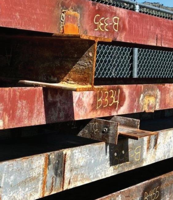
Boulder Community Hospital (Colorado, US) | Over 500 steel members were deconstructed from a community hospital and stockpiled for structural reuse. The deconstruction of the hospital diverted about 94% of material from landfill. Motivated by Deconstruction Ordinance 8366, the project team aimed to achieve 90% waste diversion. The steel stockpile is estimated to have carbon emissions savings of over 36 tons CO2e. However, the deconstruction exhibited additional labor and time costs amounting to about 20% higher costs than typical demolition. The commitment of the design and construction teams was necessary to meet the diversion requirements. The project demonstrated that structural component reuse at-scale is possible, though deconstruction and recovery costs will likely be a primary challenge for future projects.
Case study submissions are open to the general public. Design teams, developers, and all other interested parties are encouraged to submit new case studies to the library and can do so by using a simple submission form (bit.ly/SEI-CE-submit) which can also be found on the Case Studies webpage .
By growing the circular economy case studies library, design teams are better equipped with knowledge from built examples going into projects pursuing circular construction strategies. With a larger collection of case studies, the profession can gain visibility into patterns of successes and pitfalls that can inform industry-wide action and influence transformative policies. ■
Full references are included in the online version of the article at STRUCTUREmag.org
Dan Bergsagel is the international Sustainability Lead for schlaich bergermann partner (sbp) based in their NYC office and is a visiting scholar at Cornell AAP’s Circular Construction Lab. He chairs the Circular Economy Working Group for the ASCE Structural Engineering Institute Sustainability Committee.
Tracy Huynh is a senior associate in the Embodied Carbon team within the Carbon-Free Buildings Program. She leverages her expertise in structural engineering, mass timber construction, and life-cycle assessment analyses to support the team’s goals of reducing carbon embodied in building materials to meet rigorous climate targets.
By Jeannette Torrents, PE, SE
This quarterly article addresses some of the questions received about structural standards developed by the Structural Engineering Institute (SEI) of the American Society of Civil Engineers (ASCE). Questions from engineers, building officials, and other design professionals are often considered to develop future editions. These topics and more are discussed on the ASCE Peer-to-Peer Standards Exchange Forum. ASCE/SEI members can ask and answer questions in the forum. Visit https://collaborate.asce.org/standardsexchange/home to learn more and read about other topics.
I primarily design low-rise buildings in the Midwest. I know that our region has the potential for seismic activity with the New Madrid Seismic Zone, but I am surprised at how high the ground motions are for short periods in ASCE 7-22. Why such a big jump from ASCE 7-16?
Due to limited data available to inform the ground motion models in the Central and Eastern United States, the Multi-Period Design Response Spectrums in these areas exhibit a spike in spectral response accelerations at periods between 0.05 and 0.1 seconds. When using the Equivalent Lateral Force Procedure for structures with a fundamental period of less than 0.2 seconds, use the Two-Period Design Response Spectrum to obtain design seismic ground motion values. When using Modal Response Spectrum Analysis method, use the Multi-Period Design Response Spectrum to obtain design seismic ground motion values for use in the modal response spectrum analysis, then use the Two-Period Design Response Spectrum to compute the Equivalent Lateral Force Procedure Seismic Base Shear for scaling of the forces and drifts as required in 12.9.1.4. Effectively capping the design response in this way will result in safe, economical designs that comply with ASCE 7-22. For more information see “ASCE 7-22 Ground Motions – A Rational Approach for Structural Engineers” on SEI News at asce.org/sei.
When designing for drift against a relatively short projection, I don’t understand why the ASD design snow is effectively truncated at 70% of the projection height. When the drift height exceeds the clear height, shouldn’t my ASD load case be designed for the smaller of the projection height and 0.7(hb+hd) instead of for 0.7(hb+hc)?
The provisions in Chapter 7 provide a single design snow load to be used with the load combinations provided in Chapter 2. The load factors in the LRFD and ASD load combinations are applied to the design snow load, not to individual roof characteristics that
influence the design snow load. At a roof step condition, the load factor is applied to the magnitude of the load at the projection; it is not applied to the drift width or to the geometry of the roof. For a given roof, the ratio of the LRFD design load to the ASD design load when snow is the principal load is always (1.2D+1.0S)/(D+0.7S) so that the required strength determined by ASD is roughly equivalent to the required strength determined by LRFD. For the case of a short projection, the LRFD snow load (1.0S) corresponds to snow up to the top of the short projection, while the ASD snow load (0.7S) does not reach the top of the projection.
I am designing a roof and checking the thermal factor for snow loads. Why does Ct decrease as ground snow load increase? Wouldn’t a thicker layer of snow be less susceptible to heat loss than a thinner layer of snow?
Melting of roof snow due to heat flow from a heated interior space is a function of indoor temperature, roof insulation, depth of snow on the roof, and outdoor temperature. With a thin layer of snow on the roof, the temperature throughout the snow layer is more likely to be below freezing when the outdoor temperature is below freezing. With a thick layer of snow on the roof, the temperature at the roof surface is less likely to be below freezing, resulting in melting of a portion of the roof snow. For a more in-depth discussion of roof snow losses due to thermal effects, see O’Rourke, M., Ganguly, M., and Thompson, (2010), “Eave Ice Dams,” J. Architectural Engineering, ASCE Vol. 16, No. I, 9 Pages.
This article’s information is provided for general informational purposes only and is not intended in any fashion to be a substitute for professional consultation. Information provided does not constitute a formal interpretation of the standard. Under no circumstances does ASCE/ SEI, its affiliates, officers, directors, employees, or volunteers warrant the completeness, accuracy, or relevancy of any information or advice provided herein or its usefulness for any particular purpose. ASCE/SEI, its affiliates, officers, directors, employees, and volunteers expressly disclaim any and all responsibility for any liability, loss, or damage that you may cause or incur in reliance on any information or advice provided herein. If you have a question you want to be considered in a future issue, please send it to sei@asce.org with FAQ in the subject line. Visit asce. org/sei to learn more about ASCE/SEI Standards. ■
Jeannette Torrents, PE, SE, F.SEI, is the Technical Director of the Structural Engineering Institute.
Washington University School of Medicine in St. Louis has completed a six-floor vertical expansion on the Steven & Susan Lipstein BJC Institute of Health (BJCIH) building located in the center of the medical campus. The $165 million addition includes 160,000-square-feet of state-of-the-art laboratory space and was designed by St. Louisbased Lawrence Group architects.
The expansion houses a 7,400-square-foot Biologic Therapy Core Facility (BTCF), which follows Current Good Manufacturing Practice (cGMP) regulations (enforced by the Food and Drug Administration) for manufacturing cellular therapies to treat cancer; 100,000 square feet of expanded laboratory space; and about 43,000 square feet of mechanical building-support areas.
With the bulk of the project completed in December 2024, the vertical expansion includes the addition of six stories to the BJCIH building’s existing north

tower and a new elevator shaft at the northwest corner of the building.
“Lawrence Group’s design team collaborated closely with the owner’s critical facilities engineers
to develop design criteria, testing requirements, and construction details for the project and to ensure compliance with industry standards in the design,” said Lawrence Group Principal and
Healthcare Market Leader Ryan King. “The Lawrence Group team used its bank of healthcare expertise and creativity to design this unique solution for the university.”
Hannah Kessler, a PhD student at Georgia Tech is the 2025 recipient of the AISC Education Foundation’s Reidar Bjorhovde Outstanding Young Professional Award. She intends to become a structural engineering faculty member after completing her PhD this spring. Kessler holds a bachelor’s and master of science in civil engineering from Clemson University.
Kessler will attend NASCC: The Steel Conference in Louisville this month, where she’ll learn about the latest innovations in designing and building with structural steel.
Later this year, she’ll get a first-hand look at what goes on between the drawing table and the jobsite through visits to a structural steel mill and a fabrication shop. She’ll also attend the November meetings of the
AISC task committees responsible for the standards that govern structural steel design and construction.
About the Reidar Bjorhovde Outstanding Young Professional Award
Reidar Bjorhovde was a consummate professional, researcher, leader, and enormous contributor to the world's knowledge of steel structures. He had a life-long passion for mentoring bright young
professionals, whether in graduate school or just starting out in an engineering career. This award continues that legacy by introducing award recipients to steel industry leaders who will act as mentors and "connectors.”

“What is the future of structural design, and what will be the role of the structural engineer in this future?” asks James Norman, Professor of Sustainable Design at the University of Bristol, in his introduction to "The future of structural design," a new thought leadership book launched by IStructE.
As lead author, Norman is joined by other experts from academia and engineering firms to explain a possible future, founded on the theory of reliability and risk-based design.
The book explores how designers manage uncertainty now and in the future, as they look to develop new materials and work with existing buildings. A central theme is that safety must consider a wide variety of stakeholders, including those affected by climate change due to high-carbon materials usage.
"The future of structural design" advocates for the structural engineering profession to embrace a future where sustainable, circular, and regenerative approaches are considered as important as safety. It also brings advanced statistical analysis methods into the realm of the practicing engineer, using several future case studies to highlight how these tools could be used on future projects. A combination of case studies, theory and practice helps create a picture of a possible future for the profession, one which
adopts specialist methods that are currently used in fields such as earthquake engineering and offshore engineering.
The Future of Structural Design authors include:
• Dan Bergsagel, Structural Engineer, Schlaich Bergmann and Partners.
• Scott Boote, Founder, Agnos Studio.
• Flavia De Luca, Professor of Structural and Earthquake Engineering, University of Bristol.
• Raffaele De Risi, Associate Professor in Civil Engineering, University of Bristol.
• Alix Dietzel, Senior Lecturer in Climate Justice, University of Bristol, and the Associate Director for Impact and Innovation at the Cabot Institute for the Environment.
• Philip Isaac, Director and cofounder Simple Works.
• Gavin Knowles, Lecturer, Department of Architecture & Civil Engineering, University of Bath.
• Dan Maskell, Senior Lecturer, Department of Architecture & Civil Engineering, University of Bath.
• James Norman, Professor of Sustainable Design, University of Bristol and Fellow of IStructE (through the Eminent Person’s route).
Steel Deck Institute announces new edition of AISI S100 Standard for Cold-Formed Steel
The 2024 edition of this Standard replaces the 2016 editions with Supplements.
In 2023, the SDI assumed responsibility for 34 cold-formed steel standards from the American Iron and Steel Institute (AISI) when AISI withdrew from supporting those important standards. In 2024, the SDI either reaffirmed, updated, or in one case, finished the development of a new standard for 29

of the former AISI Standards. Since then, 17 standards related to cold-formed steel framing have been transferred to the Steel Framing Industry Association (SFIA) and four standards related to metal building systems have been transferred to the Metal Building Manufacturers Association (MBMA).
The 2024 edition of the S100 Standard incorporates all revisions that were approved at the time AISI withdrew from standards development. It, along with the 29 other revised standards, can be found on the SDI website for free download at sdi.org/codes-standards/former-aisi-standards/.
Products LLC
Phone: 888-704-8643
Email: connect@voidform.com
Web: voidform.com
Product: StormVoid and SureVoid
Description: Damaging soils cause significant financial loss every year. To mitigate the risk, engineers specify StormVoid and SureVoid to create space around structural concrete, allowing the soil to move without causing damage. Our forms protect beams/walls, slabs, and piers from expansive, seismic, and corrosive soil. Made in the U.S.A. and Canada.
Structural Software
Phone: 407-284-9202
Email: support@asdipsoft.com
Web: www.asdipsoft.com
Product: ASDIP Concrete
Description: Advanced software for the design of multi-span continuous beams, biaxial slender columns, concrete/masonry bearing walls, shear walls, one-way slabs and wall opening design, per the latest design codes. ASDIP Concrete easily integrates with other software to effortlessly maximize your designs with a few clicks.
Phone: 781-817-6053
Email: info@duroterra.com
Web: www.duroterra.com
Product: Ductile Iron Piles
Description: DuroTerra is a supplier of Ductile Iron Piles manufactured by Tiroler Rohre GmbH (TRM). Ductile Iron Piles provide a modular, fast, and low vibration, driven pile solution ideally suited for constrained sites with building additions and renovations with limited access and overhead clearance restrictions.
RISA Tech, Inc.
Phone:949-951-5815
Email: info@risa.com
Web: risa.com
Product: ADAPT-Builder
Description: ADAPT-Builder is powerful and easy-to-use 3D finite element software for multistory reinforced concrete and post-tensioned buildings and structures. Builder delivers comprehensive workflows for complete analysis and design. Combine gravity, lateral and post-tensioning actions for efficient, complete, and accurate design. Integrate with various BIM software for seamless project deliverables.
ENERCALC, LLC
Phone: 800-424-2252
Email: info@enercalc.com
Web: https://enercalc.com
Product: ENERCALC SEL/ENERCALC 3D
Description: ENERCALC quickly completes calculations for the design of footings, columns, beams, pedestals, slender walls, shear walls, and more. Powerful new quad meshing system simplifies complex mesh building tasks. ENERCALC includes detailed concrete earth retention design / calculation tools. ENERCALC's clear, concise reports are ideal for client/agency reviews.
ADVERTISEMENT–For Advertiser Information, visit STRUCTUREmag.org

Monthly 2025 Resource Guide forms are available on our website. www.structuremag.org
FEMA’s Building Resilient Infrastructure and Communities (BRIC) program enhances community resilience by helping states, local governments, tribes, and territories reduce hazard risks. A key principle is supporting building codes and standards that protect the public and consider climate change and future disasters.
Get immediate digital access to ASCE Standards and peer-reviewed manuals of practice instrumental to ensure compliance and required for participation in the FEMA-BRIC Program. Benefit from AMPLIFY’s exclusive features and interactive tools, making it faster and easier to work with ASCE standards.
View the full list of included publications at amplify.asce.org/fema-bric
Contact amplifytools@asce.org for more information.

In the early hours of June 24, 2021, the Champlain Towers South condominium in Surfside, Florida, partially collapsed, resulting in the tragic loss of 98 lives. In response, the National Institute of Standards and Technology (NIST) initiated a comprehensive investigation to determine the technical causes of the collapse and to recommend improvements to building codes, standards, and practices.
This special session at Structures Congress outlines NIST’s methodology, shares preliminary findings, and discusses potential implications for building design, construction, maintenance, and evaluation.


Speakers:
• Glenn Bell, Research Civil Engineer and NCST Member, NIST
• Jim Harris, PhD, Principal, J.R. Harris & Company and NCST Member, NIST
• Judith Mitrani-Reiser, PhD, Senior Research Scientist and NCST Member, NIST
New Sessions Added to Structures Congress 2025
SEI has added five sessions to Structures Congress 2025 to address current events. Topics include:
• An SEI Listening Session with SEI President Stephanie Slocum, SEI Managing Director Jennifer Goupil, and ASCE Director of Media Relations and Public Affairs Kevin Longley focused on how SEI is navigating shifts in regulatory and policy changes. This presentation includes an opportunity for attendees
to provide feedback on the challenges facing the structural engineering profession in 2025 and to explore near-term solutions and opportunities.
• Reconnaissance Insights on the Eaton and Palisade Fires: Erica Fischer, PhD, PE will present preliminary observations from reconnaissance efforts conducted in February 2025 following the LA Wildfires and will share how structural engineers can play a role in creating fire-adaptive communities.

• SEI’s SE Licensure Committee will present the complexities of obtaining licensure across various jurisdictions and the vital role of professional mobility in a global market. This session will examine landmark structures with critical public safety implications to demonstrate how licensure ensures expertise and accountability.
SEI’s Performance-Based Design Committee will review principles of performance-based design, report on the current state-of-the-art in performance-based design for fire, wind, and seismic, and preview the results of the March 2025 SEI Performance-Based Design Workshop including SEI’s 10-year vision for PBD.
SEI’s Education and Leadership Committee will engage attendees in a communication simulation designed to highlight assumptions about communication. This session supports the Education and Leadership Committee’s focus on future skilling: leading initiatives that promote leadership skills and professional growth within the SEI community.
Inspired by this year’s Congress? Submit your session or abstract for Structures Congress 2026 by June 4th, 2025, at 2026.structurescongress.org.
The nation’s most referenced infrastructure report is here! Released every four years, ASCE’s Report Card for America’s Infrastructure provides grades for 18 categories of infrastructure that Americans rely on daily—such as water pipelines, the energy grid, and transportation systems.
The report offers a snapshot of current conditions, future outlooks, and key recommendations to improve these critical systems nationwide. In 2021, the U.S. earned a “C minus”—how do we measure up today? Find out at infrastructurereportcard.org/.
The SEI Board of Governors is seeking passionate leaders to help shape the future of structural engineering. This year, three elected positions are open:
• SEI President-Elect
• At-Large Governor – Open to SEI members in good standing for at least one year
• Young Professional Governor – Open to Young Professional members in good standing for at least one year
Serving on the Board is an opportunity to influence the profession, drive key initiatives, and collaborate with industry leaders. Candidates must submit a Letter of Intent to Serve, along with a brief bio, resume or CV, and a professional photograph to sei@ asce.org by April 15.
The SEI Performance-Based Design Workshop, held in March at the ASCE Bechtel Conference Center convened leading structural engineers to redefine performance-based design (PBD). Participants explored the current state of PBD in fire, wind, and seismic design, moving beyond traditional prescriptive codes. Collaborative sessions produced a 10-year roadmap to enhance PBD standards,
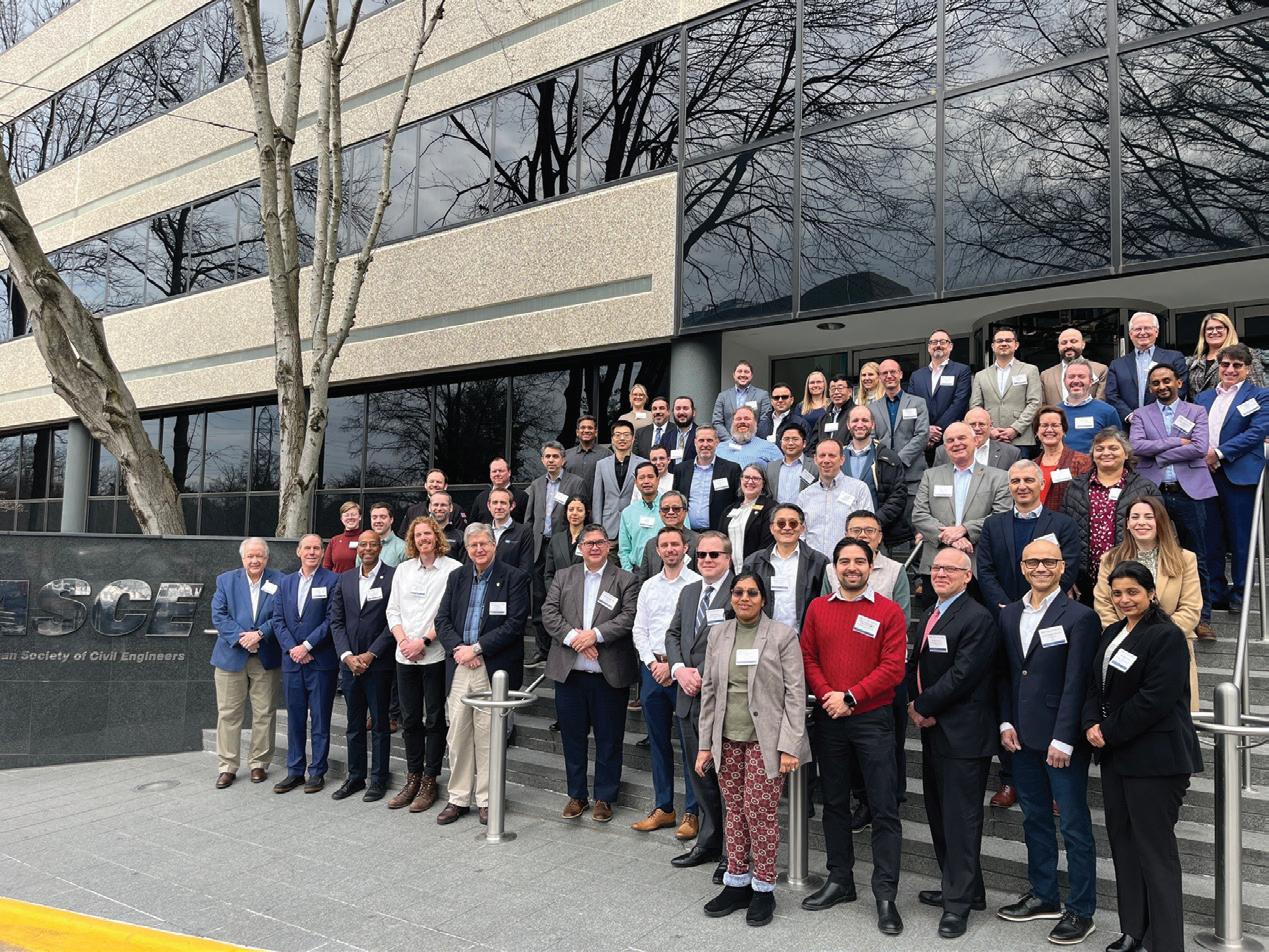
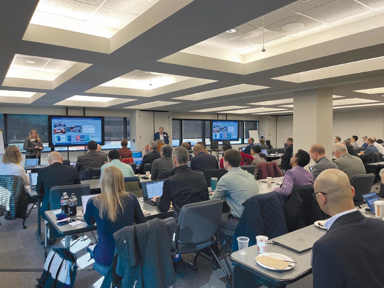
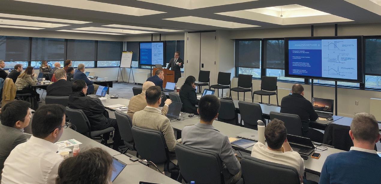
Structural engineering firm leaders from across the country convened in Napa Valley on March 5–7, 2025, for the inaugural NCSEA Structural Engineering Executive Retreat, a gathering designed to spark high-level discussions on leadership, business strategy, and the future of the profession. Approximately 75 executives participated in interactive sessions exploring firm growth, risk management, workforce challenges, and the evolving role of technology in engineering. The retreat featured a keynote address from Terry Malone, CEO and co-founder of the STEM Exploration Center, who shared insights on effective leadership in today’s evolving business environment. Attendees also explored the current state of the profession in a session led by Brian Raff of the American Institute of Steel Construction and Andrew Opdyke, CFA, Senior Economist. A panel on claims and liability, featuring Mark Blankenship (WTW A&E), Dan Allwardt (KPFF), and David Ericksen (Ericksen Legal PC), tackled key legal and financial risks facing engineering firms.
Workforce challenges were another major focus, with discussions on recruiting and retaining young engineers, ensuring competitive compensation and benefits, and leveraging AI to improve firm operations. The retreat concluded with a forward-looking discussion led by Ron Klemencic, CEO of Magnusson Klemencic Associates, on how firms can future-proof their businesses and foster innovation.
“The Executive Retreat was designed to provide structural engineering firm leaders with a space to step away from the daily demands of their work and engage in valuable conversations,” said NCSEA Executive Director Al Spada. “The level of engagement, the depth of discussions, and the connections made at this event are a testament to the strength and vision of our community.”
With strong participation and overwhelmingly positive feedback, NCSEA is already planning the next Executive Retreat, reinforcing its commitment to supporting structural engineering leaders in shaping the profession’s future.
The Perelman Performing Arts Center took center stage as the 2024 Structure of the Year during the kickoff of the 5th annual SEE Awards Webinar Series on March 13. Hosted by NCSEA and sponsored by Atlas Tube, this free webinar series highlights the achievements of each Outstanding Project winner from the Structural Engineering Excellence (SEE) Awards. Presenters are structural engineers who are deeply familiar with the intricacies of each respective project.
The series continues monthly through October: April 10 —Forensic / Renovation / Retrofit / Rehabilitation
Structures > $20 Million: The Baird Center Expansion
May 8 —New Bridges or Transportation Structures: Williams Crossing Pedestrian Bridge
June 12 —New Buildings < $30 Million: Fraser Mills Presentation Center
July 10 —New Buildings $30 Million to $80 Million: BCIT Tall Timber Student Housing
Aug. 14 —Other Structures: Minnesota Zoo Treetop Trail
Oct. 9 —New Buildings $80 Million to $200 Million: FORTH Hotel
To register, visit www.ncsea.com/seeawardswebinars. Webinars may be viewed live for 1.0 hours of continuing education, or streamed on demand at any time, with no PDHs attached to recordings. This webinar is part of the NCSEA Webinar Subscription, but all participants are asked to register to receive credit for the live event.
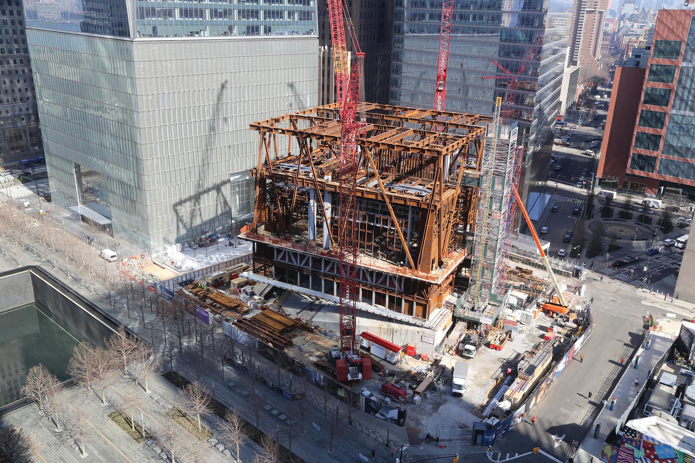
The Perelman Performing Arts Center project was the focus of the first webinar in the 5th Annual SEE Awards Webinar Series.
SEAOI members Eric Fleet and Alex Brown recently participated as special awards judges at the Illinois Regional Future City competition, held at Elmhurst University. The event featured 18 student teams from 12 schools, with SEAOI sponsoring the Most Innovative Structure award.
As judges, Eric and Alex engaged with middle school students, evaluated their creative future city models, and discussed structural considerations, including materials and design concepts. Longtime advocate of the Future City program, Bob Johnson, presented NCSEA swag to winners and photographed the event. They were all impressed by the students’ dedication, innovation, and problem-solving skills. A huge thank-you to the teachers, mentors, and SEAOI members who guided these students through the competition!
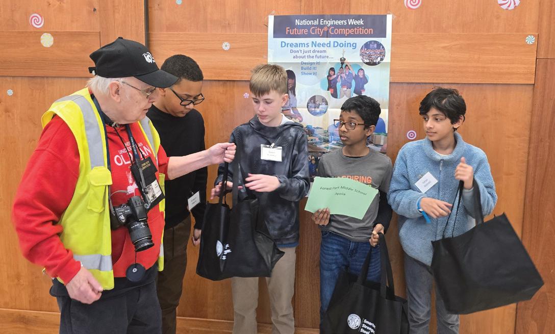


ACEC is monitoring the impact of the Trump White House on the engineering industry. You may find the link to this page on ACEC’s home page or though the QR code here.

ACEC is paying close attention to several key areas, including White House announcements to track policy changes affecting the engineering sector. Additionally, ACEC uses executive orders to understand new federal directives and actions that impact engineering practices. ACEC is also monitoring executive actions on freezing federal financial assistance to help our members navigate funding uncertainties. Finally, ACEC relies on agency memoranda and guidance to ensure compliance with regulations and support informed decision-making within the engineering field. ACEC will also host an Online Webinar on April 23 that will provide insights of the first 100 days of Trump’s Presidency. ACEC’s advocacy team will review the progress to date, provide insights on the path forward, and what it means for the engineering industry. This session is free to all ACEC members. If you would like to sign up for this event, please scan the QR code.


Consensus based Standard 240P: Harmonization of Building Industry Greenhouse Gas (GHG) Emissions will provide a methodology to quantify the embodied and operational GHG emissions associated with buildings and their sites. The standard will also provide minimum requirements for documentation of life cycle GHG emissions.
Beth Tomlinson, co-vice chair of ASHRAE/ICC Standard 240P, will provide an overview of the new standard covering whole life carbon assessment, calculation of GHG emissions, and reporting requirements.
Key Takeaways:
• Explain the pivotal role of ASHRAE’s new standards in promoting energy-efficiency and decarbonization in the built environment.
• Explore the latest updates in ASHRAE standards, focusing on whole life carbon assessment and calculation of greenhouse gas emissions.
• Explore the proposed standard’s structure of whole life greenhouse gas emissions accounting and reporting.
Presenter: Beth Tomlinson, Co-Vice Chair of ASHRAE/ICC Standard 240P
ACEC’s 2025 Annual Convention & Legislative Summit will take place May 18–21 in Washington, DC, at the Grand Hyatt, just steps from Capitol Hill. This year’s legislative agenda will have a profound impact on structural engineering firms, with Congress prioritizing tax reform, workforce policies, infrastructure investment, and regulatory streamlining. Key tax policies affecting engineers, including the 21% corporate tax rate, the 20% deduction for S corporations and passthrough firms, and the restoration of full R&D expense deductibility, will be at the center of the debate.
In addition to critical advocacy efforts, the Convention will host a CASE Roundtable with the MEP Coalition, where firm leaders will discuss pressing business issues, including risk management, liability concerns, and industry best practices.With 2025 shaping up to be a transformational year for engineering policy, your participation in ACEC’s Annual Convention & Legislative Summit is more important than ever. Join us in Washington, DC, to connect with industry leaders, advocate for your firm’s future, and stay ahead of the changes that will define the business of structural engineering for years to come.

Explore CASE’s top publications that inspire and inform professionals like you. From cutting-edge research to actionable insights, this year’s bestsellers are not to be missed. Plus, if you’re not a CASE member, don’t forget to use your discount code NCSEASEI2022 at checkout for exclusive savings.
CASE Tool 2-3: Employee Evaluations is intended to assist the structural engineering office in the task of evaluating employee performance. The evaluations provide a method to assess employee performance and serve as an integral part of the company’s risk management program.
The tool is set up as a document that can be selectively edited and customized by the user to best suit their engineering firm. It is understood that many if not all engineering offices already implement some form of an evaluation procedure, whether it be a formal and regularly scheduled event or an informal, more impromptu meeting that that is not regularly scheduled. In any case, the goal is not to advocate for the introduction of evaluations into a firm’s regular practice, as this should already be a firm policy. The goal is to present different options, new questions, new ideas and techniques that will make your firm’s evaluation procedure better.
The ability to develop young staff has always been a crucial com ponent of the success of any firm. CASE Tool No. 5-2: Milestone Checklist for Young Engineers is the second tool related to the Fifth Foundation of Risk Management – Education. The tool will help your engineers understand what engineering and leadership skills are required to become a competent engineer. It will also provide managers with a tool to evaluate engineering staff. Each item could be customized to fit your firm’s expectations.
CASE Tool No. 9-2: Quality Assurance Plan provides guidance to the structural engineering professional for developing a comprehensive detailed Quality Assurance Plan suitable for their firm. A well developed and implemented Quality Assurance Plan ensures consistent high-quality service on all projects and includes:
• Quality Control Review
• Firm-wide Standards
• Construction Quality Assurance
The complete library of coalitions documents is free to current ACEC Coalitions members. For information on joining ACEC Coalitions, please contact Alec Cherney, Coalitions Coordinator, at acherney@acec.org.

Education has the power to transform lives, but for many talented and hardworking students, financial barriers stand in the way of their dreams. The CASE Scholarship Fund is dedicated to breaking down those barriers—ensuring that every deserving student has the opportunity to pursue higher education, regardless of their financial circumstances. Right now, we have an opportunity to make a real and lasting impact. Every dollar raised goes directly toward helping students achieve their academic goals, empowering the next generation of leaders, innovators, and changemakers. These scholarships don’t just fund tuition—they fuel ambition, progress, and hope for a brighter future.

Do you know an aspiring engineer who could benefit from this opportunity? Share the CASE Scholarship with them and help open the door to a world of possibilities. To find out how to apply search “Scholarship” in the search bar on ACEC’s Home page. We need your support to continue this mission. Whether you contribute $10 or $1,000, your donation makes a difference. Together, we can open doors, create opportunities, and change lives. Join us in investing in the future. Donate to the CASE Scholarship Fund by scanning the QR code today.

SE firms face new challenges in the coming years, but strategic and proactive preparations can help firms take advantage of new opportunities.
By Kacey Clagett and Tiany Galaskas
Firm owners and leaders contend daily with the near-term challenges of finding work for their firms through market cycle ups and downs. But larger forces will increasingly play an outsized role in your company’s continuing health. Several stand out for their potential impact on your operations: demographic shifts in demand, surplus properties, shrinking labor pools, AI and other disruptive technologies, and hazard insurability. These changes could transform the ways you do business more drastically than the introduction of computer-assisted design and drafting some years ago. Smart firms will capitalize on the opportunities these disruptions will bring.
The U.S.-born population growth is declining, and thanks to advances in healthcare and a lower mortality rate among younger people, the median age is rising. According to the Congressional Budget Office, the U.S. fertility rate, which hovered around 2.02 births per woman and dropped after the Great Recession, should stabilize at about 1.70 births per woman through 2050, which is below the replacement rate for our current population. Dropping fertility rates are even more pronounced in many industrialized European and East Asian countries, whose populations are expected to shrink more. Net immigration, which has previously offset the U.S. fertility rate, is projected to drop dramatically, from 3.3 million in 2024 to 1.1 million annually from 2027 to 2054. At the same time, the Congressional Budget Office
projects the ratio of people ages 25 to 64 to people age 65 or older to drop from 2.9 to 1 in 2024 to 2.2 to 1 in 2054. The U.S. is already experiencing demographic shifts in demand. Unless fertility rates and immigration increase, firm owners should expect two things: 1) the education market will shrink, even with its new focus on lifelong learning, resulting in fewer new engineers, and 2) the healthcare and senior living markets will grow.
On a larger level, the drop in immigrant labor will prompt deeper changes felt in the national economy and in engineering businesses. Less-skilled immigrants have powered the service, construction, and agriculture industries, as well as many healthcare roles. Skilled immigrants work in engineering, as well as technology and science, and many come from countries experiencing drops in fertility rates. With a smaller native-born and immigrant workforce, economists worry that Social Security will not be able to offer the retirement incomes most older Americans depend upon, and many people would have to work longer to survive. Fewer people to fuel the economy and assist an aging population may accelerate the adoption of robotics and AI in American industry and daily life. For engineers, building expertise in changing construction technology, particularly fabrication, may expand their firm’s market position and profitability.
The Covid-related shift to hybrid and remote work has triggered
enduring changes to workplaces and to office district services. Many white-collar jobs have become partially or fully remote or stimulated demand for more offices in smaller business districts and outlying suburbs. A McKinsey Global Institute report projects office space demand in global “superstar” cities like Houston, New York, and San Francisco to drop through 2030. Engineering businesses that specialize in high rise construction have been affected by this shift for some time, and problems will persist until U.S. cities remake their office districts into vibrant places to both live and work. Engineering firms should consider advocating for downtown renewals, which may translate into business opportunities and greater professional stature.
On an operational level, if your main offices are located in such places, what will be the impact on your operations? While you may enjoy lower lease costs than before, you may face changing your business model to effectively work elsewhere without relocating.
Surplus properties
Many have suggested that office building conversions offer opportunities to recycle the existing building stock and produce needed housing while reducing construction-related carbon emissions. CommercialEdge data released in late 2024 noted that 30 U.S. cities, whose central business districts and surrounding urban submarkets hold about 167 million square feet of aging and underutilized office space, afford excellent conversion potential to residential and mixeduse, and they have even more buildings that are largely viable for conversion. Such conversions decarbonize construction.
City leaders are encouraging office-to-residential conversions and other adaptive reuses within their commercial business districts. Adaptive reuse is also attractive to institutional capital, which typically have carbon and greenhouse gas reduction goals to meet. As a global real estate investment executive commented, “the most sustainable thing is to repurpose and reuse, because ultimately, any kind of new development is adding to the current [climate change] problem.” But not every building is suitable for residential conversion, whether due to the price of the building or the need for fresh air and daylight. Some have raised more creative adaptive reuses, like data centers, or placing structural exoskeletons around obsolescent buildings, effectively converting them to podiums, and constructing towers on top of them. If carbon reduction remains a priority for the institutional capital partners funding the U.S. commercial real estate market, deconstruction and building material reuse may rise in popularity. This is already pioneered in Europe and promoted in AIA, ASLA, and Urban Land Institute conferences.
A declining population of U.S.-born citizens also affects building industry labor pools. According to Danny Bachman, former U.S. economist at Deloitte Touche, the growth of the prime labor pool of individuals between 25 to 55 years old has now slowed to 0.5% annually and will likely drop further, to 0.2% annually in the next several years, as the U.S. population ages. If our immigration policies restrict the influx of skilled professionals or the ability of recent graduates to stay in the U.S., engineering firms will have to rely on business models that use fewer people through software and other technologies, hire offshore staff, or partner with offshore firms.
Traditional growth may be more difficult to achieve, unless companies bulk up their recruitment and retention programs. Bachman says that reduced growth in available candidates will prompt companies to focus more on retention and encouraging former employees to
AI adoption is likely to underscore the importance of A/E professionals as trusted advisors and prompt firms to move into project management and fabrication.
“boomerang” back to their companies. Chris Petteys, CEO of Forell Elsesser, located in San Francisco, remarked recently that offering remote positions has given the firm stability and kept talent: “Our decision to allow people to go fully remote and move out of the area was a big retention decision. Had we not done that, my tone on the topic might be different.” Andrew Rastetter, San Francisco office director for Buro Happold, offered a slightly different angle, noting “besides the typical interest in attractive compensation—quality of life, the work environment and meaningful careers will come to the fore.” Rastetter said he focuses on getting employees to invest in their office time: “It makes a strong team ... People should prioritize this.”
Many firms already use AI to streamline work. 3-D scanners like Matterport have trimmed the time to document existing conditions and convert the data for Revit models. UpCodes speeds code research. ChatGPT and other AI technology can summarize large documents and provide findings, based on the queries they are given. Microsoft Office and Adobe Creative Cloud have AI features that can set up files and create graphics based on verbal prompts.
Autodesk continuously rolls out new advances: 3-D point clouds to map existing conditions and models that allow users to work simultaneously or manipulate datasets for different uses, and AR/VR for clash detection and virtual walkthroughs. But until the software becomes completely intuitive, firms should plan to both invest in people who can use AI to reduce their labor costs and anticipate increased hardware costs for operating AI-based software. As AI fully integrates into the market, the authors believe that clients will expect reduced fees for many traditional basic services, yet offering new services can make up for those shortfalls. Vicki Arbitrio, an Associate Principal at New York-based Gilsanz Murray Steficek said, “Harnessing AI is the only way where we can get the work done that we need to do.” Petteys agreed: “We aren’t trying to replace human positions but to enhance our work and respond to project demands,” he said. AI adoption is likely to underscore the importance of A/E professionals as trusted advisors and prompt firms to move into project management and fabrication.
Construction companies are likely to experience even more disruptions than engineers. Labor efficiency has increased in recent years, because technology and construction methods have plateaued. “We need to use robots and other machinery in construction to speed things up,” Arbitrio said. Rastetter stated, “I’ve seen a lot of evidence that this labor shortage is causing construction costs to go up. 2009 decimated the labor force and we haven’t yet recovered that, and it’s a big thing driving costs up. New technologies may help fill this shortfall … In construction, AI has the potential for bringing in quality control and reducing labor costs.”
Structural engineers could aid efficiency and reduce costs through
new technologies. “We need alternative solutions for steel and concrete,” Rastetter said. “By bringing AI and increased automation in the construction process, we can get more efficient material use. Now we design for the worstcase scenario, with all components being overbuilt, when only one needs to be. We can have in situ 3-D printing to shape a steel beam along its length. A straight extrusion is not needed, and we could reduce material and carbon. You don’t need so much material at the ends, because they don’t bend.”
Whatever your stance on climate change might be, the ability to obtain hazard insurance reckons to impact where construction will take place and how we build.
Whatever your stance on climate change might be, the ability to obtain hazard insurance reckons to impact where construction will take place and how we build. The National Oceanic and Atmospheric Administration’s “Billion-Dollar Weather and Climate Disasters” chart , which is adjusted for inflation, indicates the U.S. experienced an annual average of 3.3 “billion dollar” disasters in the 1980s. From 2013 to 2023, the annual average of such losses leapt to 19.1, with insurance rates trending upward each year. Severe storms, characterized as tornado outbreaks, high winds, and hailstorms, have risen the most. Catastrophic events like the January 2025 firestorms in Los Angeles will affect business and home insurance across the United States.
Insurability causes problems for real estate investment, both for individual building construction and for regional economies. Using the Fall 2024 windstorms in the Southeast as an example, commercial real estate executive Parren James said, “We have eliminated markets we would have typically invested in because they aren’t considered resilient. It’s not just about a hurricane striking Orlando, but the insurance costs in Florida are high, and they are increasing rapidly, which makes it difficult to underwrite the property because their share is increasing within the operating costs...You can find yourselves with an insurer who’s pulled out of the market. We can underwrite a 10% increase, but what if you can’t find an insurer? That becomes a very risky problem.” Moreover, approximately 31% of commercial mortgages are expected to expire in the next three years, 51% in the next five years, and almost 82% in the next 10 years.
Lenders expect properties to be insured. The higher interest rate environment also contributes to a greater level of refinancing risk that developers and owners must underwrite along with increased insurance prices, driving up development costs even more. The insurance industry is already responding with hazard-hardening requirements for buildings. By becoming familiar with climate resilience measures, engineers can help owners planning to build in a region experiencing insurability crises by improving the building’s resilience to flood, storms, fire, and other hazards, just as engineers in Florida have done with hurricane-proofing and seismic engineering in California. Otherwise, the owner may have to “go it on their own,” with no insurance and consequently, no outside financing, or resort to insurers with less financial capacity.
The global investment executive reinforced the problems hazard insurability poses on a regional scale, saying that their company factors in a location’s economic resilience. “I think there are markets and economies over time that will become unsustainable from a climate perspective; therefore, it doesn’t matter how good the asset performs.” Both executives noted that the real estate market will
likely bifurcate, with investors funding long-term investments in areas where climate risks are addressed, and areas with rising climate risks becoming shortterm plays for investors to walk away after a climate event, leaving communities saddled with marginal construction. The global investment executive said, “The disproportion of growth in this country is in places that are not sustainable … we might make a short-term investment while we own it, but we will expect to divest it.” If insurance and real estate capital partners pull out of high-risk areas, the U.S. could end up with greater geographic migration triggered by climate events. Engineering firms would face the choice of moving their companies elsewhere to retain their existing service offerings or adapting their business models to the owners who are willing to remain and self-finance construction.
New challenges for structural engineering companies will rise in the coming years, but these also present new opportunities, if one is willing to invest in new modes of practice to get a jump on the competition.
1. Prepare for Market Changes: Add or reinforce your expertise in market sectors that will likely grow, such as healthcare, data centers, and senior living. Expand your adaptive reuse capabilities, so owners can tap your firm as they buy up surplus properties.
2. Invest in R+D: AI and other technologies offer both costsavings and marketing differentiators for your business. Invest in staff training, software and hardware that will reduce your costs and enhance your service offerings. Investing in R+D will afford you a leg up on AI or robotic-assisted construction, help you keep your fees up, and improve your competitiveness.
3. Focus on Recruitment and Retention: Finding talent is not likely to get easier. Offer meaningful career pathways and work environments to retain your team at all stages of their careers. You may not be able to easily replace a staff member that leaves. Consider non-local or offshore staffing, which will affect your traditional workflows.
4. Customer Service Remains Central: Use new technologies to free up your team for customer service. While new technologies may minimize time spent on drafting, code checks, and calculations, your clients will always need a trusted advisor to help them navigate new construction technologies and changing codes. Be that firm.
5. Insurability Will Dominate: Owners will increasingly face situations where hardening their assets against weather and climate events will be the norm. Offer your clients regionally tailored solutions that will keep them in operation during weather events and permit them to be insured. ■
Kacey Clagett is the founder of Appleseed Strategy, which provides business strategy consulting to design and construction organizations.
Tiany Galaskas is a principal of Appleseed Strategy and founder of AECO, which provides online training in marketing and business development for the design and construction industry.