

WHERE VISION BECOMES STRUCTURE
RISA o ers a comprehensive suite of design software that work together to simplify even the most complex projects. As a result, engineers can work e ciently on a variety of structures in a mix of materials including steel, concrete, wood, masonry and aluminum. risa.com

COME VISIT US
NASCC: THE STEEL CONFERENCE Louisville, KY | April 2-4, 2025
BOOTH #211


Digital Issue

subscriptions@structuremag.org
EDITORIAL BOARD
Chair John A. Dal Pino, S.E. Claremont Engineers Inc., Oakland, CA chair@STRUCTUREmag.org
Kevin Adamson, PE Structural Focus, Gardena, CA
Marshall Carman, PE, SE Schaefer, Cincinnati, Ohio
Erin Conaway, PE AISC, Littleton, CO
Sarah Evans, PE Walter P Moore, Houston, TX
Linda M. Kaplan, PE Pennoni, Pittsburgh, PA
Nicholas Lang, PE Vice President Engineering & Advocacy, Masonry Concrete Masonry and Hardscapes Association (CMHA)
Jessica Mandrick, PE, SE, LEED AP Gilsanz Murray Steficek, LLP, New York, NY
Brian W. Miller Cast Connex Corporation, Davis, CA
Evans Mountzouris, PE Retired, Milford, CT
Kenneth Ogorzalek, PE, SE KPFF Consulting Engineers, San Francisco, CA (WI)
John “Buddy” Showalter, PE International Code Council, Washington, DC
Eytan Solomon, PE, LEED AP Silman, New York, NY
EDITORIAL STAFF
Executive Editor Alfred Spada aspada@ncsea.com
Managing Editor Shannon Wetzel swetzel@structuremag.org
Production production@structuremag.org
MARKETING & ADVERTISING SALES
Director for Sales, Marketing & Business Development
Monica Shripka Tel: 773-974-6561 monica.shripka@STRUCTUREmag.org
image by Remote Optix
STRONG. SECURE.

If seismic or high-wind challenges are important considerations for your next project, Vulcraft and Verco’s steel roof deck and PunchLok II® System is a valuable option to consider. Our team of experts can help you evaluate the variety of value-added sustainable solutions that Vulcraft and Verco offer to ensure that you have the right system in place.
Contact an expert today.

VULCRAFT VERCO

IMPROVED ECONOMY AND RESILIENCE WITH MAST FRAMES
By Jason Armes, SE; Gina Carlson, SE; and Leo Panian, SE
An innovative approach to seismic design of steel structures was taken for Samuel Merritt University’s new 10-story office, research, and academic building in downtown Oakland, California.
FEATURES


24
ENGINEERING ON DISPLAY
By Amy Barabas and Tom Barabas
With exposed CLT floors and steel framing, a large testing facility, and lattice brick work, the new building gives students numerous opportunities to see real-world engineering solutions
FOLLOWING THE EASTERN STAR
By Ryan Miller, SE, and Eric Fuller, SE
Converting a century-old meeting hall into a modern hotel requires meticulous attention to sequencing.

COLUMNS and DEPARTMENTS
Stephanie Slocum,
Michael O’Rourke, John Duntemann & John Cocca
Arun M. Puthanpurayil, Ph.D
John Dal Pino
Gwen P. Weisberg


Building Belonging in Structural Engineering
The
Thousand Little Things
By Stephanie Slocum, PE
Last week, I received a message from an earlycareer structural engineer—let’s call her Sarah. Despite graduating near the top of her class and landing a position at a prestigious firm, she was considering leaving the profession. “I just don’t feel like I belong here,” she wrote. “It’s not any one thing—it’s a thousand little things.”
Sarah’s story reflects an escalating workforce challenge. Employee engagement hit a 10-year low in 2024, costing an estimated $8.8 trillion in lost productivity globally. For structural engineers, NCSEA’s SE3 committee found that 55% of structural engineers have considered leaving the profession, with even higher percentages among women and non-white engineers. Only 30% consider our profession “attractive” compared to other STEM fields, and the top reasons cited for considering leaving were 1) stress and 2) work-life balance. Yet, those terms mean different things to different people, even those with identical qualifications. Successfully addressing these challenges requires understanding each individual’s unique context.
As structural engineers, we pride ourselves on systems thinking. We understand that structural performance depends on both individual components and how these components interact within the larger system. We analyze load paths, consider multiple failure modes, and account for how various elements influence each other. Yet, when it comes to supporting the people in our profession, we often forget these fundamental “systems-thinking” principles.
Ethical obligations within our profession are one place where systems thinking is commonly applied. For example, ASCE’s Code of Ethics, which I helped author, requires us to “treat all persons with respect, dignity, and fairness...” This professional obligation aligns with our core mission of protecting public health, safety, and welfare. Just as we wouldn’t design a structural component without understanding the complete system, we can’t effectively support our profession’s talent without understanding the personal, historical, and societal factors that influence workplace experiences.
The demographic trends speak to urgent action needed related to that talent pipeline. By 2030, the U.S. population over 65 will exceed those under 18. By 2045, the U.S. will be “minority white,” yet our engineers and architects together currently are 76.8% white and only 17.2% women. The impending student
“enrollment cliff” will further reduce our talent pool, with U.S. colleges expecting a 15% drop in students by 2039. These trends point to fewer structural professionals in the future; if we don’t create an environment where talented individuals want to stay, there may not be enough of us to meet demand—even if interest in STEM careers grows overall.
In structural analysis, we don’t assume every beam experiences the same loads or every foundation rests on identical soil conditions. Instead, good engineering requires us to investigate the specific site context, understand the unique challenges, and design solutions accordingly. Similarly, supporting individual success in our profession requires understanding each person’s unique context and creating environments where they can fully contribute their talents. Historical examples (severely limited due to max word count) demonstrate systemic barriers to success:
• Women’s financial autonomy was severely limited, with loans and credit cards requiring male cosigners until 1974.
• Discriminatory redlining prevented racial and ethnic minorities from accessing loans needed to buy homes or start businesses (illegal since 1968, with recent legal settlements as late as 2023).
• Escalating engineering education costs consume a much higher percentage of income and starting salaries compared to 20+ years ago.
These contexts do not define an individual’s potential to contribute to our profession, yet they (and many more often unseen challenges) directly impact how individuals relate to work. Instead, they represent systemic barriers that have historically constrained our profession’s ability to recruit and retain top talent.
The U.S.-based structural engineering profession’s nonprofits—ASCE’s SEI (of which I am currently President), ACEC’s CASE, and NCSEA—are uniquely positioned to address these challenges. With intentional, collaborative efforts and the ability to transcend regional political differences due to a broad national reach, we create pathways for learning, mentorship, and professional growth.
At SEI, our Professional and Technical Communities were designed to minimize silos. These communities serve as platforms for professional development. Focuses include developing codes and standards, creating sustainable design
resources, cultivating leadership, improving engineering education, and implementing mentorship programs. By bringing together people across the pro fession, we’re actively working to strengthen our profession’s talent pipeline.

Our path forward as a profession requires applying the same systems thinking we use in structural design to our professional ecosystem. This means:
• Creating intentional mentorship structures.
• Developing communication skills that bridge generational and cultural differences.
• Taking daily actions that recognize individual strengths and unique perspectives. Our profession’s future depends on creating systems that value the contributions of all types of structural professionals. We cannot allow political polarization to distract us from our fundamental ethical obligation to protect public health, safety, and welfare—an obligation that requires attracting and retaining talent from all backgrounds.
Take action today: join one of our professional associations like SEI, where you can mentor others and build connections across geographical and experiential boundaries. Seek out colleagues with different backgrounds and experiences. Understand that every human connection we build makes our profession stronger and better equipped to serve our communities. And remember—that small gesture of caring you make today could be the reason a talented engineer stays in our profession tomorrow. We all have this power. Will you use it? ■
Stephanie Slocum, PE, is the President of SEI and the Founder of Engineers Rising LLC, a firm that specializes in leadership and communications training and coaching.
structural DESIGN
Best Practices for Post-Tensioning Elongation Records
This article explores timeliness of review, the purpose of elongations and tolerances, evaluation of stressing records, and reasonable expectations for the involved parties.
By Bryan Allred, SE; Frank Malits, PE; and Neel Khosa
Reprinted with the permission of the Post-Tensioning Institute.
Post-tensioned (PT) structural systems provide effective framing solutions for a wide range of conditions, but cost effectiveness is heavily influenced by the timing of formwork cycling. For PT structures, review and approval of elongation records is a critical part of that process. This article focuses on cast in place concrete structures reinforced with unbonded post-tensioning strands which are typically used in one-way slabs, two-way slabs and beams/girder systems.
Timeliness of Review
The review process for stressing records can vary significantly across the country based on local jurisdictional requirements. In some areas, the Licensed Design Professional or Structural Engineer of Record (LDP/SEOR) does not need to be consulted if all measured elongations are within the ACI 318 allowed 7% tolerance. In these cases, the LDP/SEOR is only required to address out-of-tolerance conditions. In other areas, local jurisdictions require the LDP/SEOR to review and approve complete stressing records, even if all elongations are within tolerance, as a prerequisite step for the Contractor to cut tendon tails and continue with construction.
In the former case with out-of-tolerance conditions and in the latter case as a whole, the cycling of formwork is effectively halted until the LDP/SEOR responds. In the author’s experience, LDP/SEORs who exceed 2 days to review records do not prioritize their client and owner’s interests. In addition, reviewing elongation records for a concrete pour should take less than 60 minutes. If inattention persists, a delay claim may be forthcoming since the contractor is potentially losing significant time and money. Accordingly, the review and resolution of elongation records should be made a priority within design offices.
Timely review of stressing records also allows for faster completion of the tendon corrosion protection system. Starting with ACI 318-11, all structural building PT is required to be fully encapsulated in plastic sheathing and grease for corrosion protection. The tendon tails, however, are bare steel to accommodate stressing operations. The excess tendon tails cannot be cut until the stressing records are approved, at which time the encapsulation cap can be installed over the cut end to protect the tendon and the seated wedges. The longer the bare tendon is exposed to the elements, the potential for corrosion increases. Get the tendon ends protected as quickly as possible.

The Purpose of Elongation Records
Transferring the force from the PT strands to the concrete is critical to the performance of PT structures. Contractors must demonstrate they have complied with the contract documents, and the LDP/SEOR and building official must have confidence that the structural design has been successfully implemented. ACI 318-19 section 26.10.2(e) requires two separate actions to verify prestressing force and friction losses. First is a comparison of the measured strand elongation to a theoretical, calculated value. The second is verification of the jacking force for the rams, typically calibrated using a pressure gauge. These two actions are used individually as a check on the other.
The practical benefit of elongations is they can be observed and measured after installation of the PT force. If the inspector was not present during stressing, if the gauge pressure wasn’t recorded, or something unforeseen occurred, the elongations can still be measured as a simple way to estimate the approximate strand force. Another option would be to perform a lift-off test, which effectively is re-stressing the strands until the wedges release and recording that pressure/force. While lift-offs are performed for multiple reasons, it’s more efficient and safer for the field to measure the elongation at the tendon tail and back calculate the force. Lift-off tests can also damage the tendon. This is why elongation reports are so valuable for engineers, contractors, and inspectors. However, the elongation values need to be better understood and not used to generate unnecessary work.
Measuring elongations involves spray paint or construction keel, a straight edge, and a tape measure. Prior to stressing the strand, the inspector will place the straight edge against the slab edge and mark the exposed tendon (Fig. 1). After stressing, the same straight edge is placed against the slab edge and a tape measure shows the distance the mark has moved. This distance is the measured elongation of the strand, and the inspector will record a value for each tendon. The measuring process has its own built-in tolerance, as any measurement does.
The measured elongation is then compared to the theoretical, calculated value and the difference is documented in the report. The authors highly recommend the elongation record include the allowed +/-7% deviations from the theoretical value and the actual percentage difference between the measured and calculated values (Table 1). This helps the LDP/ SEOR quickly identify potential issues that may need contractor and
Fig. 1. Exposed strands of unseated wedges are marked with paint prior to stressing.
PT Supplier input to resolve. A typical report should provide a strand identification (color code), plan location, length of each strand and the gauge pressure of the jack.
The authors also strongly encourage the LDP/SEOR to review the equipment calibration prior to the start of construction. PT suppliers should calibrate their equipment between projects and within 6 months per PTI.
Understanding ACI 318 Elongation Tolerance
The tendon force and theoretical elongation are related based upon the strength and materials equation Δ = P*L / (A*E), where Δ is the strand elongation, P is technically the average force in the strand, but typically approximated by engineers as the anchorage force as prescribed in ACI 318-19 section 20.3.2.5, L is the length of the strand from anchor to anchor, and A and E are the strand cross-sectional area and modulus of elasticity, respectively. The theoretical elongation for each tendon is calculated by the PT supplier using the specific material properties and strand layout and is reported on the PT shop drawing submittal.
It is important for the LDP/SEOR to understand the force in the strand is not precisely proportional to the measured elongation. They are correlated, but an under-elongated strand does not immediately indicate a reduced force. There will always be differences between the theoretical and actual elongation. For example, PT suppliers, when calculating elongations, will typically use the straight-line distance between slab edges as the tendon length. In reality, a tendon is likely not to be straight due to penetrations, embedded elements or slab openings. Similar precision arguments can be made regarding friction loss, wedge seating, actual vertical tendon profile and the actual tolerance in the inspector measurements.
The ACI Code tolerance for elongations was implemented decades ago to account for numerous factors in stressing and measuring a PT strand. Concrete buildings are not constructed in a vacuum, and nothing is perfect. The 7% tolerance is not stating the code is “ok” with 93% of the force shown on the drawings. It acknowledges there will be slight differences between the theoretical and measured elongations, and provided they are small enough, that is expected and acceptable.
Out of Tolerance Elongation Records
When elongation measurements deviate from the allowable range, the design and construction team must collaboratively identify the cause. Generally, the PT supplier is to first reconfirm the elongation calculations by checking material properties and other calculation inputs. For example, on a recent project, a last-minute change to a construction joint location caused tendon lengths to differ from that used in the elongation calculations. The problem was quickly identified, and the elongation calculations were revised. If there are broken tendons or major elongation deviations, the PT supplier can conduct a more complex variable force calculation to provide additional information to the design team.
The role of the concrete contractor is to identify anomalies such as malfunctioning jacking equipment, observed anchorage slip, localized concrete defects, or other issues that could affect elongations. The role of the LDP/SEOR is to determine the impact of potentially deficient tendon forces on their structural design. All parties should collaborate on appropriate repair techniques should it come to that, to fix the problem and minimize further damage.
Short Tendon Effects
Another commonly misunderstood aspect of elongation reports is an out-of-tolerance result for short length tendons. Tiny differences between small elongation values can result in large percentage deviations. A 20-foot-long strand should elongate approximately 1-5/8 inches. However, an extra 3/16-inch wedge seating loss will produce a 12% out-of-tolerance deviation. This condition may incorrectly indicate a low force and possibly result in unnecessary remedial work. The Post-Tensioning Manual 7th Edition recommends ¼ inch be added to the theoretical elongation for strands shorter than 40 feet to account for these effects. In addition, the authors recommend relying more on verifying the applied jacking force and to view short tendon elongations with an informed eye.
Table 2. Strand “Force” from Measured Elongations
Friction Loss Calculations
The PT supplier prepares friction-loss calculations, which do not constitute a “design” of the PT system but are a verification of the theoretical tendon force for a given configuration. The tendon force is a function of many variables, but the material modulus of elasticity, angular coefficient, and wobble coefficient are specific to a given PT Supplier’s material.
The LDP/SEOR must assume a final effective PT force to produce a rationale design based on a finite number of tendons in a concrete member. Most seasoned PT designers assume a force of about 27 kips per tendon. This effective force assumption must be documented on the structural contract documents and should be verified by the friction loss calculations. The supplier is demonstrating their product can provide the force assumed as the basis of design by the LDP/SEOR. The PT supplier is not “designing” the PT system. An analogy would be rebar mill certs for deformed reinforcing steel. In many cases, LDP/ SEOR insist the PT supplier is the “PT designer” because of the friction loss calculations, which they then use as an improper basis to demand additional submittals and evaluations that are not properly the purview of the PT supplier.
Force Certifying Letters
In some areas of the U.S., PT suppliers are required by LDP/ SEORs to determine and “certify” the final installed forces based upon the measured elongations—even for tendons within the allowable 7% deviation range. Table 2 is an example of this process. This does not have a useful purpose other than to spread liability and slow the elongation review process. It is questionably unethical to require the PT supplier to “certify” construction put in place by others. The implied liability is enormous and may violate some State professional licensing laws. The authors strongly encourage all who engage in this practice to cease immediately.
Structural contract documents also might mandate: “PostTensioning Supplier shall have an Engineer supervise the stressing operations and issue a letter certifying that the prestressing forces have been transferred to the structure. The letter should also address and resolve any discrepancies.”
This specification is wildly inappropriate in the author’s opinion. The LDP/SEOR should understand the proper role of the PT supplier prior to requiring these types of letters. The PT Supplier controls the manufacturing process. The PT material is typically required to be fabricated at a PTI-certified plant, which is an ANSI certified program. Additionally, the PT Supplier has shared control over stressing equipment. After the initial calibration, onsite equipment maintenance is beyond the control of the PT supplier. The PT Supplier does not have a consistent field presence to supervise or monitor the construction phase. In the past, the PT Supplier might conduct a pre-pour jobsite visit, but this practice has become mostly obsolete due to the commonplace adoption of recognized PTI certification programs for installers, stressors and inspectors. Furthermore, the PT Supplier is not involved with the formwork, PT installation, rebar installation, concrete placement, stressing operations or elongation measurement and reporting.
Requiring the PT supplier to certify forces is not required by any code that we are aware of, adds time to the elongation review process, and increases the PT supplier’s liability for out-of-scope construction (which increases their cost to cover that risk). If the PT supplier is contracted to
fulfill the requirements shown on the structural documents, then they have already committed to providing the listed force.
Conclusion
The collective industry goal should be to advance practices and procedures that contribute to the sound design and construction of cost-effective PT structures, in a manner that is reliable, fair, and reasonable for all. ■
Bryan Allred, SE, F.P.T.I., is the Vice-President of Seneca Structural Engineering, Inc. in Newport Beach, California. He currently is a member of the Technical Advisor Board, Building Design and Education Committee of PTI, ACI 423 and is the co-author of the book “Post-Tensioned Concrete, Principles and Practice, 4th Edition”.
Frank Malits, PE, F.A.C.I., F.P.T.I. is a principal structural engineer with Cagley & Associates in Rockville, Maryland. He currently serves as a member of ACI 31825, ACI 301-26, and the PTI Technical Activities Board.
Neel Khosa is President of AMSYSCO, which is a PT Supplier in Chicago, IL. He
M-10 and
structural DESIGN
Adhesive Bond Performance of CFRP-Patched Concrete
Research shows epoxy adhesives fall short as gamechangers for CFRP patch bonding in damage resistance.
By Dr. Martin Brandtner-Hafner
In civil engineering, modern materials and techniques are crucial for enhancing the durability and strength of concrete structures. Carbon Fiber-Reinforced Polymer (CFRP) patches have emerged as an effective solution for rehabilitating beams, columns, slabs, and walls, offering high tensile strength, lightweight properties, and corrosion resistance. These patches improve load capacity and structural performance, addressing environmental and operational challenges. As the field advances toward sustainable solutions, refining CFRP patching techniques is key. This article discusses interfacial fracture analysis to evaluate the effectiveness of adhesively bonded CFRP patches in reinforcing and rehabilitating concrete structures.
A review of literature highlights extensive research on CFRP for strengthening and refurbishing concrete structures. Studies focus on improving load capacity, ductility, crack resistance, and durability to extend service life.
Key sources include Mays, Biolzi et al., and Frhaan et al., who demonstrate the effectiveness of externally bonded CFRP strips in boosting beam capacity. Research by Golham et al. and Wu et al. validates CFRP use for beams and slabs under varied conditions. Environmental impacts, such as tropical climates or heat, are examined by Hashim et al. and Al-Rousan. Methodologies range from experimental tests to finite element modeling for predicting structural behavior. The ACI Committee 440 provides a valuable design guide for Fiber-Reinforced Polymer (FRP) systems, while Nanni explores CFRP applications in civil engineering, highlighting
their versatility. Despite significant advancements, existing studies often focus on epoxy adhesives, limiting insights into CFRP-toconcrete interface failures with varied adhesives. Using a holistic fracture analysis addresses this gap by investigating shear-induced failures at adhesive-bonded CFRP interfaces, offering new insights into reinforcement techniques.
Materials and Methods
Basic Considerations
The evaluation of concrete structures falls into two categories: bulk assessment using continuum mechanics which focuses on technical stresses, and surface reinforcement assessment, where traditional methods may be insufficient. Various safety evaluation methods for bonded CFRP patches are documented, primarily using standardized continuum mechanics approaches such as compression, flexure, shear, and pull-off tests. Pull-off tests, standardized by the American Society for Testing and Materials’ ASTM D7234, Standard Test Method for Pull-Off Adhesion Strength of Coatings on Concrete Using Portable Pull-Off Adhesion Testers, 2021, and ASTM C1583, Standard Test Method for Tensile Strength of Concrete Surfaces and the Bond Strength or Tensile Strength of Concrete Repair and Overlay Materials by Direct Tension (Pull-Off Method), 2010, are particularly effective for assessing adhesion in multi-material composites.

Failure Analysis of Bonded CFRP Patches
Bonded CFRP patches aim to dampen, delay, or stop crack propagation. Figures 1 and 2 show the test specimen design: concrete blocks with U-shaped notches on each front, where CFRP strips were adhered. A cross-section view (Detail X) illustrates how CFRP patches counteract crack formation under mode-I bending-tensile stress, demonstrating their effectiveness in mitigating crack progression. Mode-I bending tensile stress refers to the stress
developed when a crack opens perpendicular to its plane under bending loads, such as in a beam or plate. Unlike pure tensile loading (like pull-off tests), bending focuses stress near the crack, better simulating how real structures fail under combined stresses. This method provides more realistic insights into material and joint behavior, especially under complex, service-like conditions.
In the study, three types of CFRP damage patches under mode-I loading were analyzed via interfacial fracture analysis. Figure 3 illustrates the damage types:
• Type A (left): The patch fails to stop crack propagation, as

mode-I loading and crack opening damage the fiber-matrix interface. This occurs due to brittle adhesives, like epoxy, which lack crack sensitivity and damping.
• Type B (middle): The crack initiates in the concrete and extends into the adhesive layer. Adhesive systems with high crackdamping properties can confine the crack within the adhesive, optimizing failure behavior. This makes Type B preferable for design.
• Type C (right): A combination of Types A and B, where the crack penetrates the adhesive and damages the patch. Although suboptimal, Type C performs better than Type A.
Evaluation Procedure
Test Candidates
The performance of various adhesive systems through fracture analysis was investigated to evaluate their interfacial reliability in CFRP-to-concrete bonding. The three adhesive types—epoxy, polyurethane, and silyl-modified polymers (SMP)—were tested for their effectiveness in bonding CFRP patches under shear loading. While epoxy adhesives dominate practical applications, research on alternative systems using fracture analysis remains limited. Details on the materials are provided in Tables 1 and 2.
Table 1 shows a compilation of the three types of adhesives used for bonding concrete structures of this study. Specifications are taken from product sheets of the manufacturers.

Fig. 2. Overview of prepared specimens. A) Pure notched concrete block; B) CFRP patch prepared with epoxy adhesive; C) CFRP patch prepared with polyurethane adhesive; D) CFRP patch prepared with silyl-modified polymer adhesive; and E) Specimen dimensions. Source & Credit: FRACTURE ANALYTICS.
Fig. 3. Schematic depiction of the three types of damage to bonded CFRP patches on concrete under mode-I loading. Source & Credit: FRACTURE ANALYTICS.
Table 1. Evaluated Adhesive Bonding Systems Used on Concrete Interfaces
Table 2. Compilation of Mode-I Loading Results of Bonded CFRP Patches Compared to Pure Concrete
Source: FRACTURE ANALYTICS. MPa = Megapascals. J/ mm² = Joules per millimeter squared. Std. Dev. = Standard Deviation
Test Setup
A setup was applied so that specimens were adhesively bonded to concrete plates and cured for seven days at room temperature (Figure 4). Testing was carried out in a laboratory on a universal testing machine. The fracture analytical events were accomplished in quasi-static loading for six samples per series. Several evaluation parameters were identified, with the results presented in Table 2. Further details about the method can be requested from FRACTURE ANALYTICS.
Results and Discussion
Basic Considerations
Two key fracture-analytical parameters—flexural notch strength
(σfn), and specific fracture energy (GF)—are used to derive an empirical structural safety factor (SF) according to Brandtner-Hafner. The results are summarized in Table 2.
The CFRP Patching Effect
A new method for evaluating the effectiveness of CFRP patching uses three adhesive systems under mode-I loading. Figure 5 illustrates the debonding process for a CFRP-patched concrete specimen. The dashed black line represents the quasi-brittle failure of an unreinforced specimen, where a primary crack forms after maximum load, propagating stably until complete separation. In contrast, the solid red line depicts the patched specimen using a SMP-based adhesive. At approximately half the maximum load (~60 Newtons (N)), Inflection Point 1 marks the onset of CFRP patch load-bearing, allowing the force to increase progressively. This increase continues until reaching 100 N, which corresponds


to 83% of the concrete-only strength of 120 N. At the peak stress point of the CFRP patches, a secondary crack initiates within their interface. The debonding process still remains stable and tough, as the flexible adhesive absorbs significant fracture energy, acting as a damping agent and providing a notable safety gain. Once the force drops to below half of the maximum load (Inflection Point 2), secondary cracks propagate until complete separation at rupture. The so-called "Safety Gain Zone," the area between Inflection Points 1 and 2, indicates the absorbed fracture energy, highlighting the desirable safety benefits of this reinforcement.
Finally, to foster a better understanding of how the bonding characteristics of the three adhesive systems influence the failure behavior of patched CFRP, Figure 6 illustrates the fracture patterns observed during the experiments.
• Section A: This shows fiber-matrix cracking in an epoxybonded patch. It corresponds to failure type A in Figure 3. Such failures arise from the brittle nature of epoxy adhesives, where cracks propagate along the fiber-matrix interface. This brittle behavior is a key limitation of epoxy-based systems.
• Section B: Here, interface delamination is evident in a

Fig. 4. Detailed illustration of test setup. Source & Credit: FRACTURE ANALYTICS.

polyurethane (PUR)-bonded patch. It corresponds to failure type B in Figure 3. The CFRP patch separates from the concrete substrate at the adhesive interface, often due to poor adhesion or mismatched mechanical properties between the CFRP and the PUR adhesive.
• Section C: This depicts a mixed failure mode in a patch bonded with silyl-modified polymer (SMP). It corresponds to failure type C in Figure 3. The failure combines fiber-matrix cracking and interface delamination, reflecting the material’s more complex behavior. SMP adhesives are tougher than epoxy, enabling better crack damping and stronger bond integrity, making them a more versatile option for such applications.
The investigation underscores the pivotal role of adhesive selection in the performance of CFRP patches for reinforcing concrete structures under mode-I loading. The analysis of epoxy, polyurethane, and silyl-modified polymers revealed significant differences in their ability to mitigate structural vulnerabilities. While epoxy allows primary cracks to propagate, polyurethane and SMP adhesives demonstrate superior crack damping and delay. Fracture analysis and Modified Compact Tension (MCT) measurements show that SMP adhesives absorb significantly more fracture energy than epoxy and polyurethane. Hybrid adhesives, combining epoxy’s strength with SMP’s fracture energy absorption, emerge as a promising solution for enhancing CFRP patch effectiveness. The findings
Fig. 5. Overview of the loading behavior of tested CFRP patch systems on the example of polyurethane adhesive. Source & Credit: FRACTURE ANALYTICS.
highlight the importance of balancing strength and fracture energy absorption in adhesive selection to optimize CFRP performance. Future applications should integrate these insights, particularly by exploring hybrid technologies to advance adhesive selection and application practices for concrete structures.
In conclusion, the study suggests reevaluating the industry’s reliance on epoxy adhesives. Emphasis should shift toward alternative systems and hybrid formulations, alongside long-term performance studies, to support the development of sustainable and resilient infrastructure. ■
Full references are included in the online version of the article at STRUCTUREmag.org
Dr. Martin Brandtner-Hafner, born in Austria, pursued his studies in industrial engineering and materials science at the Vienna University of Technology. Following his doctoral research on “The Empirical Safety Evaluation of Structural Adhesives,” he established FRACTURE ANALYTICS, a private R&D consultancy specializing in the empirical evaluation and certification of adhesives, composites, and multimaterial interfaces.

Fig. 6. Fracture patterns of various cracked CFRP patch variations. Section A: fiber-matrix cracking of EPOXY bonded patch, Section B: interface delamination of PUR bonded patch, Section C: Mixed failure of SMP bonded patch. Source: this study.
Engineering on Display
With exposed CLT floors and steel framing, a large testing facility, and lattice brick work, the building gives students numerous opportunities to see real-world engineering solutions.
By Amy Barabas and Tom Barabas

The Engineering Design and Innovation (EDI) building is the new gateway to innovation on the expanding west campus at Penn State University Park. With large, column-free spaces, exposed structure, lattice pattern brick, and expansive glass, the 105,000 square feet structure provides an opportunity to witness engineering at every turn. Sprinkled throughout the building are nearly 10,000 square feet of machine shops and manufacturing labs. Topped with five long-span raised roof monitors with clerestory windows for natural light, the fourth level open loft provides students and teachers with a flexible maker space. Isolated from the classroom portion, a three-story high bay housing two 20-ton gantry cranes and a substantial strong wall/reaction floor delivers a unique testing area for experimental research.
CLT Hybrid Structure—Design Challenge 1
Early design iterations for the classroom structure examined multiple solutions for the building framing system, and it appeared initially that a traditional concrete on metal deck with steel beam composite construction would be the least expensive option. However, as the push for sustainability gained momentum and the design and construction teams learned more about CLT and a possible hybrid solution, the decision to use CLT was made.
The project grid consists of a 32-foot spacing in the north-south direction and beam spans of 25-foot, 6 inch, 54 foot, 6 inch, and an additional 12 foot, 8 inch cantilever in the east-west direction. The dimensions were critical in the decision to switch from a traditional composite system to a hybrid system. With a composite floor, two beams would be required within each bay to keep the deck span to approximately 11 feet. However, with five-ply CLT, the deck span could increase to more than 16 feet, allowing one beam to be removed in each bay.
Floor framing design began with verifying allowable span lengths for the CLT panels with respect to strength and vibration. Various CLT manufacturer tables were reviewed to arrive at the final thickness of the CLT panel given the chosen beam spacing and the species of wood the architect preferred. The design team determined that 2 inches of normal weight concrete topping reinforced with 6x6-W1.4xW1.4 W.W.R. above the CLT panels would suffice for acoustic concerns. At the time of the design, limited references were available detailing design for vibration with a CLT hybrid system. The team chose to analyze the CLT by following Chapter 7 of the CLT Handbook and to analyze the

Photo by Warren Jagger
Photo by Warren Jagger
The CLT floor and steel beam framing were left exposed to highlight the building's structural characteristics.


non-composite steel beams by following the vibration requirements set forth in AISC Design Guide 11. Due to the long spans, many of the supporting steel beams increased in size and required the additional dead load that the 2 inch topping provided to remain under the recommended acceleration tolerance limit of 0.5%.
The lateral system for the classroom section consisted of steel braced frames and moment frames relying on the CLT panels to act as a diaphragm. Details between the CLT panels and the steel beams were carefully reviewed to ensure that the diaphragm forces were properly transferred into the lateral system. MTC ASSY Kombi screws were used between the underside of the top flange of the steel beams and the underside of the CLT for both CLT panel to steel beam typical connections as well as CLT chord splices. MTC ASSY Ecofast screws and ¾-inch thick sheathing strips were used along the top side of the CLT panels for panel splices. Both size and spacing were based on the shear per linear foot that need to be transferred.
The EDI building, designed under IBC 2015, is Type IIIB unprotected combustible construction with a 2- hour fire rated exterior bearing wall between the existing garage and the new building. As such, the steel beams and bottom of CLT could remain exposed.
Overall, because the steel beams were not composite, they increased in weight, while the total number of pieces used decreased. The combined weight of the CLT with the additional 2 inches of normal weight topping was very similar to that of the composite slab on deck, so column and footing sizes remained comparable to what they would have been with a traditional steel building. There was a learning curve for the entire design team and increased coordination between disciplines. However, the speed of installation of the CLT panels coupled with the reduced embodied carbon, confirmed that this was the correct design choice for the project.
Strong Wall/Reaction Floor—Design Challenge 2
Part of the high bay program required a strong wall and reaction floor that will be used to complete testing on new and innovative structural products and designs. The strong testing walls and floors each have a grid of pipe sleeves that run through the wall and floor allowing for Dywidag tie rods which are used to anchor the testing apparatus to the wall and floor.

Completed strong wall reinforcing prior to pouring concrete.
Isolation joint detail between high bay and classroom to mitigate vibration transmission.
Strong wall reinforcing layout.
The force is transmitted to the testing specimen by a hydraulic actuator that is set to deliver a specific force at a given frequency.
The strong wall is 30 feet tall and 2 feet thick between pilasters and buttresses. In plan, it is L-shaped with the long leg approximately 60 feet and the short leg 23 feet, 8 inches. The high bay’s west wall location was set by an adjacent existing parking garage. The space between the west wall and the back side of the strong wall, including testing wall pilasters, had to maintain clearance for a scissor lift to pass between the two. To provide the maximum amount of testing space in front of the strong wall, and maintain the clearance behind it, it was determined that the longer wall would be reinforced with shallower pilasters and allow for testing that required a lower loading capacity. The shorter wall reinforced with longer T- shaped buttresses provides areas for testing at a higher loading capacity.
The short wall was designed for 250 kips at the top and mid-height of the wall, while the long wall was designed for 150 kips at the top and mid-height of the wall, apart from the free end which had a reduced load of 110 kips. The reaction floor is 2 feet thick and has a clear span of 8 feet, 10 inches between 14-inch-thick walls below the testing floor. The wall and floor thickness were limited based on a request to keep the Dywidag rod length reasonable for the users of the facility. So, in addition to the vertical and horizontal reinforcement on each face, the walls and floor required #5 single leg stirrups at 6 inches on center in both directions. Post-tensioned tendons were also installed vertically within the wall to help limit cracking and improve overall performance.
For several reasons, the design team specified that the strong wall be poured monolithically with no joints. During the design team’s research, including discussions with other teams that had built strong walls, it was discovered that the difficulty of leveling the concrete and the preparation of the construction joint were common issues that this team chose to avoid. The alignment of formwork between separate pours
was also a concern that would be alleviated by a single pour. The wall was specified to limit surface irregularities to 1/16”, so eliminating any variables that could allow misalignment was critical.
The wall contains over 250 tons of reinforcing steel and 450 post tension cables, resulting in a level of congestion a standard concrete mix could not feasibly overcome. To meet this challenge, the concrete supplier designed a self-consolidating concrete mix that met all the specified requirements. Typically, full liquid hydrostatic head must be considered for self-consolidating concrete when designing the formwork. With a formwork height of 30 feet, the pressure on the forms at the base of the wall would be considerable. To ensure the proposed upgraded formwork would work, the concrete subcontractor performed mix specific studies to determine cure rates while keeping pressures below the allowable pressure of the upgraded formwork system. Additional mix considerations included a shrinkage reducing admixture and smaller aggregate due to the reinforcing congestion.
Isolation Joint—Design Challenge 3
While the high bay is a 3-story open space, the original design included a shared basement wall between the high bay and the classroom side, as well as shared framing between the high bay roof and the fourth level CLT floor. After discussions with the vibration consultant, consideration was given to mitigate vibrations created by both testing performed in the high bay and overhead crane use from impacting the classrooms and offices. This resulted in unique isolation details along the first floor and a full -height expansion joint above grade. The addition of the expansion joint lead to the need for a separate lateral system for the high bay, comprised of CMU shear walls, steel braced frames and moment frames.

by
Photo
Warren Jagger

to be 5 5/8 inches wide to satisfy the stress requirements.

RECORDS
Eliminate the hassle of resubmitting your
College transcripts
Exams results
Employment verifications
Professional references each time you apply for licensure in an additional state.
Build your NCEES Record today. ncees.org/records
Photo by Warren Jagger
The raised roof monitors with clerestory windows and open floor plan create a lively and energetic maker space.
Low Carbon Concrete—Design Challenge 5
Having significantly reduced the embodied carbon on the project by using CLT, the design team set their sights on lowering the carbon in the concrete. Since the addition of low carbon concrete was introduced late in the project, the requirements were considered an alternate to be vetted by the Construction Manager. Due to cure times of concrete with high supplemental cementitious materials (SCM), only certain elements of the building were included for the alternate mixes. These included elements that could take longer to reach strength without affecting the schedule, such as the footings, interior and exterior foundation walls, and the interior topping.
The concrete supplier used a combination of slag and E5 Liquid Fly Ash to replace the portland cement. The footing and interior wall mixes were able to receive the highest replacement of portland cement (48%), while the exterior walls and interior topping mixes were only marginally better due to w/c ratio and placement concerns. However, all the concrete mixes beat the National Ready Mixed Concrete Association regional benchmarks, which are typically less than 20% SCM, helping the project reach its sustainability goal.
From the CLT to the strong wall, many of the EDI’s challenges were novel to both the design and construction teams. Thanks to extensive coordination and collaboration, discussions with other engineers and builders and open communication, the project was completed successfully. With this project, along with the rest of the expanded west campus, it is an exciting time for Penn State Engineering. ■
Amy Barabas, PE and Tom Barabas, PE are both Principals at Hope Furrer Associates, State College Office. They are also both alumni of Penn State and truly proud to be a part of this project.

CRSI’s popular design Guides are indispensable resources for structural engineers, educators, students, building officials, and individuals studying for licensing exams.

Print and digital versions available! Visit the CRSI web store for specially priced packages!
Seismic Design Guide for Steel Reinforced Concrete Buildings
Design Guide on the ACI 318 Building Code Requirements for Structural Concrete
Photo by Warren Jagger

The purpose of this Design Guide is to assist in the proper application of the earthquake provisions in the 2019 edition of Building Code Requirements for Structural Concrete (ACI 318-19) and Commentary (ACI 318R19) for cast-in-place concrete buildings with nonprestressed steel reinforcing bars. Visit www.crsi.org
Design Checklists
With over 140 worked-out examples, this unique Design Guide assists in the proper application of the provisions in the 2019 edition of Building Code Requirements for Structural Concrete (ACI 318-19) for cast-inplace concrete buildings with nonprestressed reinforcement.
Companions to the CRSI Design Guides on ACI 318-19, these Design Checklists are easy-to-use lists of essential items that must be completed when designing and detailing steel reinforced concrete structural members in accordance with the 2019 edition of the ACI 318 Building Code.

ADVERTISEMENT–For Advertiser Information, visit STRUCTUREmag.org
The lattice brick above the glass pop-out maintains the facade aesthetic while allowing light into the interior lounge space.
Following the Eastern Star
Converting a century-old meeting hall into a modern hotel requires meticulous attention to sequencing.
By Ryan Miller, SE, and Eric Fuller, SE
Abuilding that sits vacant for decades is a target. Graffiti, broken windows, rodent infestation, roof leaks, and sun deterioration all attack it until it becomes a blight in the cityscape. If that building is an unreinforced brick masonry structure in seismic country, the odds of that building making a comeback are slim. Such was the case for the Eastern Star Hall in Sacramento, California. Thankfully the Eastern Star Hall's listing on the National Historic Register improved its chances of survival.


Top: A staircase leading to the mezzanine room, bar and restaurant above is a focal point of the finished entry lobby of the Eastern Star Hall.
Right: A temporary bracing platform was utilized at the lobby area gable walls.
Opposite page: Structural steel is installed around the temporary bracing.

The Order of the Eastern Star is an international organization that involves women in the Masonic Order. It was established in 1850 by Master Mason Dr. Rob Morris whose mission was to share Masonic principles with women. The first chapter in Sacramento, CA, was formed in 1879. The Order began to grow quickly such that by the 1920s there were five chapters in Sacramento. Scheduling events among the five chapters within the existing facilities at the Masonic Lodges proved challenging, so the Order of the Eastern Star held fundraising events to construct a new building. Local firm Coffman, Sahlberg, and Stafford Architects designed the Eastern Star Hall in the Classical Revival style, and it was built by the Masons themselves in 1928.
By the end of the 20th century, as membership in the Order was declining, the building went unused. They tried renting out the building to non-Masonic organizations, however the age of the building and resulting code violations, such as the lack of an elevator, eventually prevented its further use. By 1992, the Eastern Star Hall was the only surviving building out of four in the United States that were built specifically for the Order of the Eastern Star. The building was vacant for roughly two decades. Hume Development purchased the property in 2018 with a preservation-forward focus. Their vision to preserve the main facade, the entry lobby with its staircase, the portion of auditorium floor above the lobby, and the east and west brick walls for the full length of the building would bring a contemporary and much-needed revitalization of the property. Although foundation settlement had caused
cracking in the brick walls and the auditorium floor to be out of level, the finishes were in fairly good condition. The interior lodge rooms and most of the auditorium would be demolished and replaced with an eight-story, 128-room hotel while still retaining the original character and charm that the public once knew. Therein lies the intriguing structural challenge of demolition and reconstruction amid constraints of existing elements on a tight downtown site.
Purpose Built
With a footprint of 70 feet by 145 feet and an exterior wall height of 62 feet, the original building looks more like a five-story building even though it is only three stories. From the main entry lobby, a grand staircase wraps around each side of the atrium as it guides visitors up to either the main lodge rooms or to the third-floor auditorium 30 feet above the lobby. The two main lodge rooms are 60-foot square and boast ceiling heights of 20 feet. The auditorium features stadium seating at the south and a stage at the north, with 10-foot-deep steel angle roof trusses above that clear-span the building, providing a large open ballroom for special events. The building also has a full basement complete with a kitchen and stage used for banquet events.
The lobby with adjacent lounge rooms extends 36-feet from the main entry facade. Additional lounge room mezzanines are halfway up the staircase. The existing

structure comprised wood solid sawn floor joists supported by steel wide-flange girders and columns on shallow foundations. The exterior unreinforced masonry (URM) shear walls are largely non-load bearing due to the embedded steel columns within the walls.
While the construction materials of the original building are common among structures of this era, the unique geometry and layout of the interior spaces sets the stage for the complex conversion that revitalized the building.
Internal Bracing Systems
Achieving Hume Development’s vision proved to be a formidable task. The most challenging aspect of the project was the sequencing of demolition and reconstruction. An approach to stabilize the three facades and the lobby with its staircase was developed using a bracing system installed on the interior of the building; external bracing was not feasible due to the close proximity of adjacent buildings. The internal bracing was designed using loading criteria from American Society of Civil Engineers (ASCE) 37 Design Loads on Structures During Construction. It was carefully woven into the existing structure
so that it did not inhibit the removal of the existing structure while also staying out of the way of future permanent construction.
The predominant bracing for the east and west exterior walls involved a series of vertical steel trusses cantilevered from the foundation and spaced at about 16 feet on-center. The trusses integrated the existing W10 steel columns that were buried in the URM walls and one level of interior columns as the chords of the trusses. Additional columns were spliced onto the interior columns and interlaced with steel HSS diagonal braces. The bracing trusses were supported on existing exterior wall footings and new micropiles at the interior columns. Each individual piece of the bracing truss was located with an eye toward the future new construction so that it did not prevent installation of the final structural system.
The bracing at the existing lobby area required a different solution because a portion of the existing auditorium floor and the lounges below were to remain. The URM walls extended another 30 feet above the auditorium floor to the highest gable end peak. These were braced by adding two temporary levels of wood diaphragms above the existing auditorium floor. The diaphragms spanned to URM return walls or to temporary steel braced frames. Diagonal wood kicker braces stabilized the gable end walls down to the temporary floor.
Mat slab reinforcing within the exterior unreinforced masonry was 28 inches thick and installed at the existing basement level.
Additionally, the upper temporary floor had a waterproofing layer installed to help keep rainwater off the existing lobby finishes below. Installation and removal of all temporary elements were coordinated in tandem with the new structural elements. Where a temporary element passed through the new structural floor, it was treated as an opening in the floor and subsequently patched back after removal of the bracing. The only location where a new gravity beam conflicted with the bracing system was where the floor deck was vertically shored with temporary stud walls to complete the floor diaphragm and thereby brace the existing walls. Only then was the bracing system deconstructed and the final beam inserted to support the floor.
Integrating New Elements With Existing Construction
The new 86,000 square foot structure for the eight-story hotel consisted of concrete-over-metal-deck floors with steel beams and columns supported on a mat slab foundation. The steel beams were aligned with guestroom demising walls and corridor walls to implement 10-foot floor-to-floor heights. This system was inserted into the shell of the perimeter URM walls and enveloped the existing lobby at floors five through eight.
A mat slab foundation 28-inches-thick was installed at the existing basement level. The mat slab was analyzed using CSI SAFE which provided demands at the interface with the existing URM wall footing along the perimeter. This interface was evaluated and detailed with epoxy dowels to consider the mat and the wall footing as integral members. The new lateral system consisted of buckling-restrained braced frames tucked into corners and tightly placed along edges of the building. Where the braced frame columns landed on the existing wall footing, that portion of the footing was cut out and replaced with a new reinforced grade beam element within the mat slab. This was especially important at the corner columns to ensure that the frame column was properly supported by the mat.
The new lateral system serves as the primary lateral support for the existing structure. The 2016 California Building Code (CBC) governed design of all new systems, however the 2016 California Existing Building Code - Appendix A1 (CEBC) was used to evaluate the out-of-plane capability of the existing URM walls. These walls spanned the short 10-foot floor-to-floor distance where the concrete diaphragms delivered out-of-plane loads to steel buckling-restrained braced frames. The three-wythe URM walls easily met the heightto-thickness ratios of the CEBC. For loading parallel to the URM walls, the connection to the floor was detailed to allow movement of the floor relative to the wall such that the wall was decoupled from in-plane lateral forces of the new structure and only resisted its own inertial seismic loads. This was achieved by wrapping foam on the epoxy rebar dowel tension ties so that they had room to flex in-plane for the expected building drifts.
Two shotcrete shear walls were placed against the primary URM entry facade with cutouts where the existing windows occurred. The purpose of these shotcrete walls was two-fold: to support gravity loads from the new fifth-floor framing as it extended over the top of the existing lobby, as well as to provide in-plane shear resistance for the main facade. Since the new steel lateral system was decoupled from the perimeter URM walls, special care was taken at this level. The interface of the fifth floor to the existing URM wall included a seismic joint with slide bearings to allow the perimeter walls to only resist their own in-plane inertial loads, while out-of-plane loads
Project Team
SER: Buehler
Owner: Hume Development
Architect: HRGA
Contractors (primary and specialty): Market 1 Builders
Structural Software Used: CSI SAFE, ETABS, and RAM Structural System
were supported by the new concrete diaphragm. The new concrete walls rested on a pair of micropiles at each end and included pile caps detailed to underpin the existing facade wall to mitigate settlement that had opened up a 2-inch crack between the lobby area and the northern portion of the building.
Anchoring into the URM walls was achieved using drill and epoxy bolts or rebar. Concrete elements such as shear walls utilized epoxy rebar dowels while steel elements utilized threaded bolts. Capacities for the anchors were taken from the ICC code report for the epoxy system since most of the URM walls in the building were three-wythes in thickness as the code report requires. However, some anchors were required in the two-wythe former parapet of the east and west walls. For these instances, a project-specific anchor testing program was performed by pull-testing anchors installed in a portion of the parapet that was ultimately slated for demolition to justify usage of epoxy anchors in the 8-inch URM.
Keeping the eight stories below the CBC high-rise floor limit of 75 feet required that the new third floor be set 16 inches lower than the existing third floor level. Due to space constraints in the guestroom layout, it was determined that the recess to accommodate a wheelchair lift and stairs connecting the existing level to the new level needed to occur within the existing framing. This recess required about 10 inches of an existing 16-inch steel beam be cut out. The beam was strengthened by adding a new wide-flange beam welded to the underside that extended beyond the cutout portion to connect the existing beam to its supporting girder.
A New Beginning
The hotel welcomed its first guests in January 2023. Visitors can enjoy the renovated lobby and learn about the Order of the Eastern Star and Sacramento history in the reading room adjacent to the lobby. The guestrooms include a kitchenette and workstation which are attractive to those who need a longer-term stay option, perhaps when visiting patients at nearby Sutter Medical Center. The third-floor bar is open to the public to enjoy the character of this unique building. The Eastern Star Hall is once again thriving in the community thanks to the vision of the development and design teams. ■
Ryan Miller, SE, LEED AP, is an Associate Principal at Buehler (rmiller@ buehlerengineering.com). Eric Fuller, SE, is a Principal at Buehler (efuller@ buehlerengineering.com). Miller and Fuller have over 60 years of combined experience spelunking through existing buildings seeking hidden structural treasures.
Improved Economy & Resilience With Mast Frames

By Jason Armes, SE; Gina Carlson, SE; and Leo Panian, SE
The challenges of selecting the appropriate seismic system involve the trade-offs and compromises between architectural design, space planning, construction cost, and seismic performance. For Samuel Merritt University’s (SMU) new high-rise research, and academic building in downtown Oakland, California, an iterative design approach resulted in a novel and cost-effective structural system that provides an unobstructed floor plan and superior seismic performance. Working closely with the developer, contractor, and architect team, Tipping, as the structural engineering team, investigated different design strategies, including moment frames, dual systems, conventional Buckling Restrained Braced (BRB) frames, and Buckling Restrained Mast-Frames (BRBM) to develop the most effective approach. This allowed the team to make detailed comparisons of
Rendering of Samuel Merrit University's new campus headquarters in Oakland, California (Courtesy of Perkins & Will).
Project Team
Structural Engineer: TippingArchitect: Perkins&Will
Owner: Samuel Merritt University
Developer: Strada Investment Group
Contractor: Hathaway-Dinwiddie Construction Company
Steel Fabricator: The Herrick Corporation
BRB Supplier: CoreBrace
architectural impact, material use, and seismic performance to arrive at the preferred solution.
The system ultimately selected is a variation of the conventional BRB frame, which incorporates a vertical mast or strongback element. This configuration, referred to as a Buckling Restrained Braced Mast (BRBM) frame, effectively separates the elastic and energy dissipating components of the system resulting in a more resilient and reliable structure. The mast element consists of a vertical truss that is designed to stay elastic and work in conjunction with BRB devices, which yield and dissipate seismic energy.
The BRBM system has been used in previous projects, but the SMU example is the largest and tallest application of the innovative system. The compact footprint of the BRBM frames allowed them to be largely concealed within permanent demising walls. Their inherent redundancy allowed for fewer frames in the building and significantly reduced the number of BRB devices, both minimizing the impact to interior spaces and resulting in overall cost savings.
Case Study
The new high-rise building will serve as the flagship campus for Samuel Merritt University. The nursing and health science education

Structural System Summary
• Plan Dimensions: 218 feet by 115 feet
• Height: 146 feet to roof, with 23-foot deep basement
• Bay Spacing: 23 to 42 feet
• Floor Assembly: 6¼-inch lightweight concrete slab over metal decking on wide-flange beams and columns
• Seismic Load Resisting System: Buckling restrained braced frames with mast elements
• Foundation: Mat slab supported on unimproved soil


facility, which is slated to open in 2026, will feature classrooms, laboratories, clinics, offices, and community gathering spaces. Though the building is located on a dense urban site, setbacks from neighboring buildings allow for a large majority of the facade to consist of a glazed curtainwall providing views and access to natural light. An offset vertical circulation core allowed for large unobstructed classrooms and flexibility for lab planning.
Initial Design Concepts With Moment Frames & Dual Systems
During the conceptual design phase, Tipping initially investigated a moment frame system to ensure that the variety of uses could be flexibly accommodated. Frame member sizes were governed by seismic deflection criteria and were proportioned to limit the maximum interstory drift to 2.0%. The resulting system required numerous frame lines with deep beams, heavy columns and intersecting columns with custom shapes. It also came with a significant cost premium due to the relatively high quantity of steel required, estimated at 9 pounds per square foot of floor area. Due to its inherent flexibility and increased propensity for damage, the momentframe system provided the least resilient approach.

Estimated maximum drifts for the design basis earthquake (DBE), comparing response spectrum analysis (RSA) and non-linear response history analysis (NLRHA), with limits for Risk Categories (RC) II and III.

The structural design team also evaluated a dual system, which combined BRB frames in each direction to supplement the moment frames. The intent was to leverage the stiffness of the limited number of brace frames to limit drift and reduce the overall quantity of steel. Due to incompatibilities in stiffness between the moment frames and braced frames, effective load-sharing between them was difficult to achieve. This dual system would still rely on heavy moment frames to resist a minimum of 25% of the total seismic load, as required by the ASCE 7 code. With the addition of 40 BRBs, the dual system resulted in a slight reduction of overall steel quantity, with estimated total of 8.7 pounds per square foot of floor area, and a modest improvement in performance, with an estimated inter-story drift of 1.85%. While the dual system was an improvement over the moment-frames alone, it provided only limited gains in performance or economy.
Key advantages of the BRBM system include its ability to maintain an open floor plan and maximize facade transparency while significantly improving seismic performance.
Buckling Restrained Brace (BRB) System
In further exploring potential design solutions, the design team investigated concentrically braced frames relying entirely on BRBs. Due to the limited number of frame bays that were available to locate diagonal braces, the system needed to be designed for a 30% increase in lateral loads to account for the lack of redundancy
Illustration shows inelastic mechanism of BRBM frame, with yielding BRBs on the left half working in tandem with an elastic mast on the right. The mast truss incorporates W14x665 columns and W14x233 diagonals and is capacity-designed to protect against overload.
Construction of BRBM frame showing uniform member sizes and connections.
of the system. This led to heavy, built-up column sections and very large BRB members, particularly at the lower stories, where the lateral loads were the highest.
Despite the redundancy penalty, the BRB frame system offered a significant improvement in terms of cost, performance, and impact to the architectural design. This approach resulted in a significantly reduced quantity of steel for the lateral load resting system, estimated at 3.2 pounds per square foot of floor area. The system incorporated a total of 100 BRB devices and resulted in a significantly reduced maximum inter-story drift of 1.70%.
While this represented a reasonable and cost-effective solution that met the basic design goals, there was an opportunity to further improve the seismic resilience of the building. Our analysis showed that despite the fact that seismic drift was well below the code limit, the BRB devices were only partially mobilized to resist seismic shaking. The team observed that most of the lateral deformation and damage tends to concentrate at individual stories and components rather than being more evenly distributed, significantly limiting overall seismic resilience.
BRB Mast System
To mitigate these shortcomings and develop a more optimal scheme, the design team investigated a system that incorporates a vertical mast or strongback within the braced frame to augment the BRBs. This variation of the conventional BRB frame effectively separates the elastic and energy dissipating components of the system to better control structural response and improve seismic performance. This approach relies on a full-height truss, made of conventional wide-flange sections, that works in conjunction with the yielding BRB devices to improve the redundancy and performance of the system. The rigidity and strength of the mast significantly reduces the maximum expected seismic drift and ensures a more uniform drift distribution throughout the height of the building. This effectively eliminates story mechanisms and localization of damage resulting in a more resilient and reliable structure.
By interconnecting all of the BRB devices throughout the height of each frame, they are fully utilized and capable of sharing loads between stories. This effectively improves the redundancy of the system and eliminates the 30% penalty, leading to increased efficiency.
These advantages can be gained with minimal or no cost premium over a conventional BRB-only frame system. Ultimately, this approach resulted in an estimated steel quantity of 480 tons or 3.7 pounds per square foot of floor area for the lateral load resisting system. This represents a slight increase from the conventional BRB-only system, owing largely to the incorporation of the vertical truss that serves as the mast. However, this system used only 50 BRB devices, making up the cost of the additional steel quantity.
The maximum drift for the BRBM system under the design basis earthquake (DBE) was estimated to be 1.20% using a Response Spectrum Analysis (RSA) and 1.30% using a Non-linear Response History Analysis (NLRHA). The ratio of maximum-to-average drift over the height of the building was 1.09, indicating a relatively uniform drift profile with no concentration of story deformations. This

level of performance is a significant improvement over conventional practice that can provide measurable gains in seismic resilience.
The BRB mast frame system was designed using the prescriptive procedures outlined in Chapter 12 of ASCE 7-16 and the AISC Seismic Provisions for BRB frames described in Chapter 5.5, using an R-value of 8. The design method was adapted for the treatment of the mast truss and extensively validated using non-linear static and dynamic analyses.

Each frame-bay incorporates a mast truss on one side and a single BRB device on the other. The mast side is typically proportioned to be slightly narrower than the BRB-side, making the devices more efficient in resisting horizontal loads and longer allowing increased deformation capacity. Under elastic load levels, the mast truss resists roughly 40% of the total base shear. Because the truss is designed to remain elastic under all loading conditions, it can make all of the BRB devices in the frame to share the total load. This allows the BRBs to be more uniformly sized throughout the height rather than becoming increasingly larger towards the base, simplifying detailing and avoiding extreme proportions.
To ensure that the system performs as intended, the mast members were proportioned using capacity-design principles, an approach that is analogous
Illustration of BRBM base connection that uses a shear lug to transfer horizontal forces and four 10-foot long, 2.5-inch diameter, high-strength rods to resist overturning tension forces, while allowing rotational flexibility.
Mast frame construction with facade and fire proofing partially installed.
to the design of columns in the frames. Once the BRB sizes were determined using a preliminary response spectrum analysis and optimized for a more uniform distribution of forces, the forces in the mast truss were amplified to reflect the maximum anticipated loads that could be delivered by the yielding BRBs. Initially this consisted of applying an overstrength factor of 2.5 to estimate the required demands on mast members. This approach was reasonably effective for estimating the maximum loads on the mast truss. To validate this critical assumption, we deployed non-linear analyses to capture the inelastic response of the system and refine the design of the mast members and BRBs.
To allow the mast frames to rock and pivot more freely about its base and prevent overstressing the gravity support columns, the design team developed an improvised pin connection that could resist large shear and overturning axial forces while allowing rotation. The detail relied on direct steel-to-steel contact at the base connections to deliver axial compression and shear. To transfer tension forces, Tipping called for long high-strength rods to anchor the base of the mast.
The design was submitted for plan review and approved through a conventional permitting process, which did not require a special Alternate Materials and Methods Request or formal peer review.
Conclusions and Take-aways
The implementation of BRBM frames represents a significant advancement in the seismic design of steel structures, particularly for high-rise applications like Samuel Merritt University’s flagship campus. Through an iterative design process that evaluated various structural systems,
including moment frames, dual systems, and conventional BRB frames, the BRBM system emerged as the optimal solution, balancing costeffectiveness, architectural flexibility, and seismic resilience.
Key advantages of the BRBM system include its ability to maintain an open floor plan and maximize facade transparency while significantly improving seismic performance. By integrating a vertical mast truss with BRB devices, the system minimizes story drift, eliminates damage concentrations, and enhances system reliability, resulting in improved structural response during earthquakes. This innovative approach also reduces the overall number of BRB devices and avoids excessive column and beam sizes, addressing common architectural and economic challenges associated with traditional systems.
The design process underscores the importance of tailoring structural solutions to project-specific needs and site constraints. The use of advanced analytical techniques, such as non-linear static and dynamic analyses, further validated the BRBM system’s capacity to meet stringent safety, serviceability, and resilience requirements. This achievement not only sets a precedent for future seismic designs but also highlights the potential of collaborative engineering to drive innovation. ■
Leo Panian is a Principal with Tipping and served as the Structural Engineer of Record for the project. Gina Carlson is an Associate Principal with Tipping and served as the Project Director. Jason Armes is an Associate with Tipping and served as the Project Manager and Technical Lead.


codes and STANDARDS
Roof Snow Drifts Due to Ground Snow
In some circumstances, such as low eave height and strong winds, snow that originally fell on the ground can contribute to a roof top snow drift.
By Michael O’Rourke, John Duntemann & John Cocca
For the last 40 years, design provisions in the United States for roof snow drift loads have accounted for snow which originally fell on one portion of the roof and was transported by wind into a snow drift atop another portion of the roof. Specifically, for a leeward drift roof at a step, the upwind fetch lu references the upper-level roof snow source area. Similarly for a windward drift at a roof step, lu addresses the lowerlevel roof where the snow originally fell and eventually ended up in the drift. Finally, for a gable roof with a east-west ridgeline, the across the ridge drift (aka the unbalanced load) atop the northern portion of the roof, l u is that for the southern portion of the roof. Note in all these cases, snow which originally fell on the ground is not considered as an expected snow source for a roof top snow drift.
However, in certain circumstances, snow which originally fell on the ground can contribute to roof snow drift formation. In one real-world case, the building was a hog containment structure in the Midwest with a roof eave relatively close to the ground surface. The gable roof drift was larger than what one would expect for the roof’s upwind fetch lu
A second case involved a school building in the Buffalo area which experienced the Blizzard of 1977. According to Wikipedia, the total snow fall was over 8 feet in some places, while peak daily wind speeds were in the 45 to 70 mph range. As sketched in Figure 1, Roofs A and C were one story portions of the school while Roof B (thought to be a gymnasium space) had a higher elevation. A windward drift “snow
ramp” was on the ground upwind of Roof A (snow source being snow which originally fell on the ground). Similarly, a windward snow ramp was atop Roof A, immediately upwind of the exterior wall between Roofs A and B (snow source being snow which originally fell on the ground or fell on Roof A). Finally, a large leeward drift was atop Roof C (snow source being snow which originally fell on the ground, Roof A or Roof B).
The mechanism for such ground-to-roof snow transfer is a windward drift which forms at the building upwind wall. When this ground snow drift becomes large enough, it provides a “snow ramp” for windblown ground snow particles to end up atop the building roof.
The drift formation process for windward drift is more complicated than that for leeward drifts. Leeward drifts have a right triangular shape throughout the drift formation process. Initially the slope is about 1:4, thought to be the average angle of repose for drifted snow (i.e. 14°). As the top of the leeward drift approaches the upper-level roof, the slope flattens out until it reaches a rise-to-run of about 1:8. At this point, the drift becomes aerodynamically streamlined (region of aerodynamic shade eliminated) and the growth of the leeward drift stops. The trapping efficiency for leeward drifts during the drift formation process is about 50%, that is, about half of the snow that is blown off the upperlevel roof ends up in the leeward drift atop the lower-level roof.
The initial shape of a windward drift is an acute triangle, not a right

Fig. 1. Snow drifts at a Buffalo, New York, school after the 1977 blizzard is illustrated.
triangle. So, unlike leeward drifts, the high point of the initial windward drift surcharge is not at the wall. When the windward drift is small with respect to the wall height above the ground snow ho, (see Figure 2) the trapping efficiency towards the center of the wall (i.e., away from the corners) is nominally 100%. That is, during this initial phase, all the windblown snow stops upwind of the building wall and contributes to drift formation, as opposed to flowing up onto the roof.
When the windward drift obtains the shape shown in Figure 2, the snow ramp is large enough that some of the wind-transported ground snow particles reach the building roof and the trapping efficiency at the ground surface windward drift drops below 100%.
Using relations in ASCE 7-22, the expected height of the 50% trapping efficiency leeward drift, hd, is
where P g is the design ground snow load (pounds per square foot - psf), lu is the upwind fetch of the upper-level roof (ft). W2 is the winter wind parameter (i.e., percent time the wind speed is above 10 mph during October through April) as given in an ASCE 7-22 map and γ is the snow density (pounds per cubic foot-pcf). Equation 1 was based on simulated snow drifts with upwind fetch distances of 1,000 feet or less. Since the width of the leeward is taken to be 4hd, the corresponding cross-sectional area of the leeward 50% trapping drift Ad is
The cross-sectional area of the windward ground snow drift in Figure 2, Aw, is
However, due to the difference in trapping efficiencies (100% for windward, 50% for leeward), the windward drift Aw cross-sectional area is twice that for the leeward drift or
Hence, the upwind ground snow fetch lu* corresponding to wind transported ground snow particles beginning to flow up the snow ramp and onto the roof is
Table 1 presents lu* for ground surface to roof eave distances, h, of 6, 8, and 10 feet for various values of the Winter Wind parameter W2 and P g = 10 psf. Using the ASCE 7 relation for snow density, γ = 0.13 P g + 14, the ground snow depth for Pg = 10 psf is hg = 0.65 feet and the corresponding ho values in Table 1 are 5.35 (ho = h – h g = 6 – 0.65), 7.35 and 9.35 feet respectively. As one would expect, the transition upwind ground snow fetch lu* is an increasing function of the eave height, h, and a decreasing function of the Winter Wind Parameter W2
Note that for P g = 10 psf, if the eave height is 8 feet or larger, the upwind transition ground snow fetch lu* would need to be larger than a football field (approx. 360 feet) for wind driven ground snow to reach the building roof.
Tables 2 and 3 present the same lu* information for P g = 30 psf, (hg = 1.68 ft and corresponding ho values of 4.32, 6.32, 8.32 and 10.32 feet)
and for P g = 50 psf (hg = 2.43 ft and corresponding ho values of 3.57, 5.57, 7.57 and 9.57 feet).
For a location with a typical or average Winter Wind Parameter of 0.45, P g = 30 psf, and a ground snow upwind fetch of a football field (approximately 360 feet), one does not expect ground snow to reach the roof level and contribute to a roof top drift if the eave height is 10 feet (580 feet > 360 feet). For the same W2 value and ground snow fetch, if P g = 50 psf, one does not expect ground snow to contribute to a roof top drift if the eave height is 12 feet (610 feet > 360 feet).
Ground Snow Fetch
Besides the eave height, ground snow load, and the Winter Wind Parameter, the key parameter for ground snow contributing to the roof drift is the ground snow load fetch distance. While determination of the roof fetch is straight forward, the ground snow fetch distance is
Table 1. Transition Ground Snow Fetch lu* (in feet) for Pg = 10 psf
Table 2. Transition Ground Snow Fetch lu* (in feet) for Pg = 30 psf
Symbol + indicates fetch larger than 1,000 feet.
Table 3. Transition Ground Snow Fetch lu* (in feet) for Pg = 50 psf

more complex. Tabler (1994) has written “The upwind end of the fetch is any boundary across which there is no snow transport, such as forest margins, deep gullies or stream channels, row of trees, and shorelines of unfrozen bodies of water.” Tall brush can also be added to this list. For some locations (short eave height buildings close to a frozen lake) the upwind ground snow fetch could be measured in miles as opposed to a building roof fetch which typically is less than a thousand feet. As a matter of fact, as noted above, the largest building roof fetch considered in the determination of Equation 1 is 1,000 feet. For very large ground snow fetch distances, evaporation of ground snow as it is being transported comes into play, which was not considered in the development of Equation 1.
Roof Drift Due to Ground Snow
If the expected ground snow fetch from the previous paragraph, lg , is larger than the transition ground snow fetch lu* in Tables 1 through 3, some of the ground snow transport would add an amount Ad* to the “normal” drift cross-sectional area due to wind induced transport of snow which initially fell atop the roof. The additional amount is given by
Depending on the magnitude of the ground fetch lg, Ad* could be quite large. In such cases the size of the roof top snow drift would not be larger than the corresponding aerodynamically streamlined “maximum” drift. For either a leeward or windward roof step, the maximum drift would be a right triangle with height hc and a horizontal extent 8 h c where h c is the space available for roof step drift accumulation (roof step elevation distance minus balanced snow depth). For a gable roof geometry, the “maximum” drift is sketched in Figure 3. The top of the drift close to the ridgeline is nominally flat, while close to the eave the drift slope can conservatively be taken as 30˚ which is the assumed maximum angle of repose for drifted snow.
Conclusions
Currently roof snow drift provisions do not envision ground snow blowing up and onto the roof. However, there are certain circumstances, low eave height and strong winds, wherein snow which originally has fallen on the ground contribute to a roof top snow drift. This article has provided procedures for estimating the size of such roof drifts. ■
Full references are included in the online version of the article at STRUCTUREmag.org .

Michael O’Rourke is a Professor Emeritus of Civil Engineering at Rensselaer. He served as the chair of the ASCE 7 Snow and Rain Load subcommittee from 1997 thru 2017.
John F. Duntemann, P. E., S. E. is a Senior Principal at Wiss, Janney, Elstner Associates in Northbrook, Illinois. He is the current Chair of the ASCE 7 Snow and Rain Subcommittee and a Fellow of the Structural Engineering Institute (SEI).
John Cocca, P. E., is an Associate Principal at Wiss, Janney, Elstner Associates in New Haven, CT. He is the Vice Chair of the ASCE 7 Snow and Rain Subcommittee and a member of the Structural Engineering Institute (SEI).
Fig. 2. The shape of ground surface windward drift (snow ramp) at the transition to trapping efficiency less than 100%.
Fig. 3. The maximum snow drift for a gable roof is sketched.
structural FORUM
Sustainability in Structural Design in High Seismic Regions
Combining viscous dampers with advanced structural design technologies can be effective in identifying optimized retrofit solutions.
By Arun M. Puthanpurayil, Ph.D
With the growing focus on climate change and the pressing need to reduce construction-related carbon, the need for sustainable structural design is imperative. According to a 2019 World Green Building Council report, the built environment contributes 39% of global carbon emissions, with 11% from embodied carbon, which includes emissions from manufacturing, transport, construction, and end of life phases of the built environment. According to the studies, this percentage could rise to 50% of new construction's carbon footprint by 2050. Thus, a shift from building new structures to retrofitting and retaining existing ones is essential to minimize embodied carbon. Minimizing upfront and embodied carbon is the primary “focus."
“Seismic Issue” in Sustainabilty
In seismic regions, minimizing embodied carbon while ensuring seismic resilience presents a major challenge. Conventional ductiledesign strategies often lead to significant damage and rebuilding after earthquakes, as seen in events like the Christchurch earthquake, where about 70% of the buildings in the Central Business District had to be demolished (costing NZD $45 billion, which amounts to approximately 20% of New Zealand’s GDP). To retain existing buildings in such high seismic areas, a completely different approach is required. Retrofitting existing structures with solutions like viscous dampers is yielding cost-effective retrofit solutions and significantly enhanced seismic resilience.
Viscous Dampers—A Means to Seismic Resilience
Viscous dampers are highly effective in reducing earthquake impacts on buildings in seismic regions. These fluid-mechanical devices generate forces proportional to velocity, counteracting structural
displacements and accelerations. If properly designed, they reduce both drift and floor acceleration, helping to minimize building damage and downtime, providing enhanced resilience during and after an earthquake. Especially for retrofit, they are more efficient than other technologies like base isolation, as they require less extensive foundation work and superstructure stiffening which is often very costly. The key to their (viscous damper incorporated retrofit) effectiveness, however, lies in the quality of the retrofit design. The key question that arises is what do we really mean by “if properly designed” and why is it important to include this qualification? A typical section of a viscous damper is shown in Figure 1.
Why Do We Need a Properly Designed System?
Equation 1 in the sidebar "Mathematical Modeling of Viscous Dampers," describes the dynamics of a building equipped with viscous dampers during an earthquake. This equation may be visualized as a triangle, with three pivotal figures occupying the corners, symbolizing the key forces involved: Sir Isaac Newton (representing inertia), Robert Hooke FRS (representing the nonlinear restoring force), and Lord Rayleigh (representing damping). Together, they form the left-hand side of the equation (1). When an earthquake strikes a building, an inherent “debate” takes place on how the total load will be distributed among them—essentially, how much resistance each will contribute to counter the imposed earthquake forces. This complex interaction, or "load sharing," makes the problem of earthquake engineering highly complex. Adding mechanical devices like viscous dampers only amplifies this complexity, as they introduce additional layers of resistance and force distribution. Traditional methods of design for conventional structures (structures without dampers) incorporate numerous simplifications to this phenomenon of “load sharing” mainly for mathematical convenience.
Typically, the “proper design” of a viscous damper incorporated


Fig. 1. The damper consists of a stainless-steel piston inside a steel cylinder which is divided into two chambers by the piston head. The cylinder is filled with a compressible hydraulic fluid and a pressure accumulator for smooth fluid circulation. (Images courtesy Taylor Devices Inc.)
structure adopts the Performance Based Design (ASCE41/FEMA P58) using nonlinear time history analyses. This involves subjecting the proposed design to a suite of ground motions (usually 11 bi-directional ground motions) and establishing that it satisfies the relevant compliance requirements and target performance criteria. Variations in material properties also need to be factored into the design.
The standard industry approach is to extrapolate the simplified design approaches normally used for conventional structures to those incorporating viscous dampers. This results in an initial starting point. From there, we have observed engineers reverting to an intensive "brute force" process, where multiple analyses (in the range of 1,000s) are conducted to refine the system. This involves varying damper locations and parameters in an effort to optimize the design. Depending on the building size and complexity, this iterative process can take months or even years to arrive at a compliant design.
Each iteration requires significant computational effort. For one intensity level, a single iteration involves 22 nonlinear time history analyses. Since there are usually at least three intensity levels (Serviceability, DBE, and MCE), each with specific performance requirements, this means that one iteration realistically entails 66 analyses, if all intensity levels are considered simultaneously. Depending on the building's complexities, multiple intensity levels may need to be considered simultaneously during the design process and hundreds to thousands of iterations may be necessary, making the process computationally intensive and extremely time-consuming. As a consequence, engineers have needed at times to terminate their efforts once they have achieved what they deem to be a compliant design as opposed to persisting in pursuit of an optimized design that consumes less material and achieves superior performance. The resulting designs tend to be material intensive, driving up cost and carbon emissions, while often falling short of achieving optimal performance.
Now why does this happen? The primary reason for this inefficiency lies in the "brute force" approach itself. In this method, engineers lack the ability to assess the complex load-sharing process that is crucial for determining the ideal placement and sizing of the dampers. Without a clear understanding of how loads are distributed across the system, it becomes nearly impossible to strategically quantify and position the dampers. This lack of insight leads to a

Mathematical Modeling of Viscous Dampers
The equation of motion (EOM) incorporating the viscous dampers is:
Mü(t)+C structure ů(t)+f damper (t)+f NL (t)=-MIü g (t) (1)
where:
Mü(t) represents the inertia of the system.
Cstructureů(t) represents the inherent damping in the system. fdamper is the vector of forces in the structure due to the dampers. fNL is the vector of nonlinear restoring forces in the structure.
MIüg(t) represents the seismic loading.
Depending on how fdamper is represented in the analytical formulation, the viscously damped system may be analytically classified as either a pure-viscous system or as a Maxwell system.
In a normal time-history analysis for seismic engineering, the semi-discretized equations given in Equation 1 is temporally discretized and solved using implicit integration schemes.
To address these challenges and facilitate smooth commercially viable applications of Performance Based Design approaches (ASCE41/FEMA P58), a proprietary smart design platform called MOODD, based on advanced PBSD principles was developed. This platform produces design solutions explicitly accounting for these intricate physical interactions. By optimally tuning these “load sharing” interactions, the platform generates designs that not only enhance seismic resilience for a given cost, but also promote sustainability through reduced upfront carbon emissions. In addition to PBSD, the platform also has the capability to generate designs based on Performance Based Wind Design (PBWD) principles where the wind dynamic loading is considered which maybe applied for tall and super tall buildings. Two real life applications of the platform for retrofit for seismic loading are described in this article.
8 Willis Street, Wellington, New Zealand

8 Willis Street is in the Central Business District of Wellington. The city rests on the meeting point of two tectonic plates and is prone to large earthquakes. Major fault lines very close to the city include the Wellington Fault, the Wairarapa Fault, and the Ohariu Fault.
The Wellington fault may be able to generate earthquakes larger than magnitude 8.0 and may generate ground velocities around or larger than 1.5 meters/second and ground displacements greater than 2 meters. Obviously a retrofit design in Wellington should cater to these sorts of extreme seismic demands.
The seismic rating of the existing structure built in the 1980s (Fig. 2) had fallen below what is acceptable for a commercial office space.
To improve the commercial viability and future-proof of the existing asset, property developer Argosy, headquartered in Auckland, New Zealand, decided to retrofit the building to be 130% New Building Standard (NBS) along with increasing the floor area from 6,500 square meters to 11,750 square meters.
The primary structural system of the original building was comprised of reinforced concrete moment frames in one direction and shear
Figures 2-3. This 3D image on the left depicts 8 Willis Street in the 1980s with floor area of 6,500 square meters. At right is the building as of 2022 after the retrofit.
walls in the other direction. The floor system was precast hollow-core concrete floors, and the foundation system was shallow pads.
Recent earthquakes like Kaikoura (2016) revealed the vulnerability of hollowcore flooring systems during earthquakes. The main issues relate to loss of seating (where a unit slips away from its support), positive moment failure, negative moment failure, and web splitting which are all drift/ rotations related very similar to issues exhibited by preNorthridge connections. These issues were all present at 8 Willis Street.


33 Bowen Street, Wellington
The increase in floor area was achieved by adding five stories on the top of the existing eight stories and a 13 meter extension to the street front (Fig. 4). Figure 5 shows the retrofitted and enhanced 8 Willis Street building in the present day.
Performance based seismic design using the smart design platform was applied for the retrofit design incorporating fluid viscous dampers. The primary retrofit scheme includes twelve viscous dampers arranged in the moment frame direction. The fluid viscous dampers are tuned in such a way that the overall building performance met the target requirement of the client with no additional foundation work for seismic loading. Seventy ground motions scaled to NZ 1170.5:2004 were used for the design. Aleatoric and epistemic uncertainties were explicitly accounted for in the design. An independent peer review of the entire retrofitted structure was done by the world-renowned Earthquake Structural Engineer and Structural Dynamist Prof. Emeritus Athol J. Carr (author of 3D Ruaumoko software) from University of Canterbury, New Zealand.
The final retrofit had more floors without dampers than with dampers and met the Architectural requirements of having uninhibited floor plates for maximum functionality. A typical arrangement of fluid viscous dampers is shown in Figure 6.
The adaptive reuse of the structure alone resulted in saving a whopping 1904 tons of carbon.

33 Bowen is a 12-story reinforced concrete moment-frame building designed and constructed in the 1980s, incorporating precast hollow-core floors (Fig. 7). The moment frames were well-designed and detailed for expected design level according to NZ 4203:1984 which is the predecessor of the current New Zealand code NZ 1170.5:2004. Figure 7 shows the existing side elevation of the building.
Beca's seismic assessment rated the building at 35% NBS, just above "earthquake prone" status, with the low rating due to hollow-core diaphragm issues and the frames nearing code drift limits. Coupled with shear failure concerns from beam overstrength not accounting for slab reinforcement, the deficiencies identified led to tenants vacating. The situation was further exacerbated by new GNS Science data indicating a 90% hazard increase for the site.
The commercial chaos caused by the tenants vacating due to the low seismic rating made the owners decide that the retrofit needed to account for potential future changes to the loading standard that are anticipated to incorporate the updated National Seismic Hazard Model. It was decided that for future proofing, 80% of new seismic hazard will be the target. This sets the target strengthening for the existing building at 150% NBS based on current hazard.
To achieve the target of 150% NBS, nearly a four-fold increase in seismic resistance was required. Even to achieve 70% NBS (twice the current rating of 35%) through conventional means of strengthening would demand an enormous amount of intervention, both in the foundations and in the superstructure. So, achieving 150%
Fig. 6. A typical viscous damper in 8 Willis Street is shown.
Fig. 7. 33 Bowen Street in Wellington, New Zealand, is a 12-story reinforced concrete moment-frame building constructed in the 1980s.
Figure 4. The scale of the retrofit 1980s structure and the 2022 structure is illustrated.
Fig. 5. The adaptive reuse of 8 Willis Street (shown today) resulted in a savings of 1,904 tons of carbon.


NBS through traditional means of strengthening was impractical from a cost perspective with an associated negative consequence from a carbon perspective. In addition to financial infeasibility, this intervention will also affect the functional and aesthetic aspects of the building, rendering it un-lettable. To ensure an attractive commercial outcome, a smart retrofit strategy was necessary—one that would deliver significantly higher performance with minimal intervention and at a more acceptable cost.
Viscous dampers were chosen for the project due to their "out of phase" response to structural forces. However, to achieve the desired performance, the retrofitted system had to be “properly designed” considering the “load sharing” phenomena. Traditional design methods, which conveniently and incorrectly ignored these effects, couldn't meet the project's objectives of performance and cost. The client only considered the project to be financially/ commercially feasible, if 150% NBS rating could be achieved at a cost which is less than the cost of conventional strengthening for a target of 70% NBS. To achieve this, the PBSD using the smart design platform was employed to generate the design. The obtained design was then evaluated using the NZ 1170.5:2004 alternative solution compliance pathway to demonstrate compliance.
Figure 8 shows the ADRS (AccelerationDisplacement Response spectrum) curve for the existing structural system, the drift of the uncontrolled (without dampers/ original structure) was around 9% in MCE earthquake (blue line in Figure 8) and 5% in the DBE (green line in Figure 8). The target drift was chosen as less than 1% in DBE (a five-fold reduction) and less than 2.0% in MCE (a four-fold reduction) to mitigate the hollow-core issues as per the recent experimental research guidance from SESOC (The Structural Engineering Society of New Zealand). To put these drift targets in perspective, it is worth noting that the standard compliance drift target for NZ codes is 2.5% for DBE.
Figure 9 represents the drift plots for both longitudinal and transverse directions of the
building when subjected to multi-directional earthquakes. Maximum inter-story drift in DBE is around 0.8% and the maximum inter-story drift for MCE is <1.8%.
Implementing the smart design platform at 33 Bowen dramatically reduced on-floor work, making the retrofit process far more cost-effective than conventional design approaches. As shown in Figure 10, the comparison between traditional and PBSD designs using this advanced framework reveals that the design solutions incorporating the “load sharing” effects of physics results in significantly more sustainable solutions with minimal initial carbon footprint. Moreover, the smartly designed viscous dampers negated the necessity for any foundation work due to substantial reduction in the base shear.
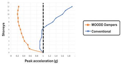

Figure 11 illustrates the viscous damper arrangements in 33 Bowen. The damper locations are confined to the perimeter frames to avoid introducing any obstructions on the open-plan floor plates.
Conclusions
The article highlights the effectiveness of combining viscous dampers with advanced structural design technologies, such as the smart design platform, to identify optimized retrofit solutions. This approach has proven successful in enabling cost-efficient seismic retrofitting of buildings with significant vulnerabilities (drift and acceleration related) in high seismic regions. The resultant retrofit solutions achieved a substantial reduction in total cost and embodied carbon compared to that possible using conventional analysis and design techniques and obviously even greater savings when compared to the alternative of the demolition and reconstruction of a replacement building. ■
Arun
M. Puthanpurayil is a Technical Fellow in Advanced Seismic and Wind Design and a Technical Director of Structural Dynamics at Beca Ltd., New Zealand
Fig. 9. Inter-story drift plot of the damped structure.
Figure 8. Acceleration-Displacement Response spectrum curve for 33 Bowen Street.
Fig. 11. Typical damper layouts of viscous dampers are shown for 33 Bowen.
Fig. 10. Floor acceleration plot for 33 Bowen.
structural FORUM
Seismic Retrofit Ordinances Part 2— Understanding Earthquakes
Besides the structural aspects of a building, geologic effects as well as non-structural hazards need to be addressed in any retrofit.
By John Dal Pino
Ihave heard that many engineers from non-seismic regions are scared by seismic design. I feel the same about wind design, and after listening to other presentations at the Alabama conference I attended, that feeling has only been reinforced. However, to put the non-seismic regions at ease, if you can understand the basics of the vibration of a single-degree of freedom, lumped-mass system and follow a load path from the roof to the ground, you know enough to design most structures for earthquakes.
In terms of behavior, the underlying basis of seismic design is that certain elements in the building need to survive the earthquake with a degree of damage permitted (called deformation-controlled elements or perhaps better, yielding elements) and some elements in the building (called force-controlled or non-yielding elements) cannot be damaged because they are relied upon to deliver the seismic load generated by the mass of the building to the yielding elements. This simple concept exists implicitly in the provisions of the building code, but the code unfortunately never states it explicitly as its foundational basis.
Like windstorms, earthquakes come in all “shapes and sizes” with different durations, ground shaking intensity, frequency content, etc. But the goal of the building code is for the building to hang together until the shaking stops in what might be considered a repairable condition in the design basis earthquake. The design basis earthquake (DBE) is nothing more than the envelope of seismic design forces for all structures, from short, stiff structures (short fundamental period of vibration, say 1 second or less) to tall, less stiff structures (long fundamental period of vibration, say 3 seconds or more) in what is called a spectrum. The engineer can achieve the repairable condition goal with either (1) massive strength so that no or little damage occurs or (2) reliably ductile elements that are damaged during the earthquake and then repaired after.
The engineer, in consultation with their client, can select from several commonly defined seismic performance goals, unless the building code otherwise establishes a minimum goal based on occupancy:
• Operational—Essentially no damage meaningful to operations. Think nuclear power plants.
• Immediate Occupancy—Some minor damage but still able to operate. In California, hospitals are designed to this goal, K-14 schools similarly.
• Life Safety—Significant damage but most occupants are safe and can exit the building. The building should be economically repairable. This is the default goal for most new buildings, except schools and hospitals in California.
• Collapse Prevention—The building remains standing with
some residual strength but may be a total economic loss. In California, this is the goal that is often used for the seismic retrofit of historic structures.
In general, the earthquakes that have largely shaped the current seismic provisions of building codes are:
• 1971 San Fernando Earthquake (Los Angeles)—Known mostly for damage to concrete buildings (Olive View Hospital and Veterans Administration Hospital) and concrete highway structures (Caltrans overpasses).
• 1989 Loma Prieta Earthquake (San Francisco Bay Area)— Known mostly for the collapse of the double deck, concrete Cypress Structure (elevated Caltrans roadway in Oakland), wood-framed apartment buildings with “soft” first stories (San Francisco Marina District), and damage to a few buildings with welded steel moment frame connections. At the time, the enormity of the impending welded connection issue was not widely understood nor appreciated.
• 1994 Northridge Earthquake (Los Angeles)—Concrete parking garages, welded steel moment frame connections, concrete Caltrans overpasses and wood-framed apartment buildings, with open, tuck under parking.
Frankly, an engineer needs to be my age or older to personally remember any of them. Even the Northridge earthquake occurred 30 years ago. Prior to 1971, there hadn’t been a major earthquake in a heavily populated area in the continental U.S. in a very long time, and there really hasn’t been one since.
The remainder of this article, and the next part in the series which will be published later, will focus on seismic retrofit ordinances. However to really understand the seismic engineering field and what constitutes a complete retrofit, it is important to note that in any retrofit, besides the structural issues i.e the building itself, geologic effects need to be considered (fault rupture, soil liquefaction, settlement, landsliding, etc.) as well as non-structural hazards (contents, ceilings, walls, MEP systems, etc.). See Figures 1 and 2 for ground effects at bridge abutments and soil liquefaction.
A very good book that contains a great collection of historic
Seismic retrofits of a mandatory nature have an implied performance target, but the structural engineer needs to educate the owner and determine if a higher goal should be targeted.


earthquake damage photos, basically showing everything that “could go wrong,” is Earthquakes, Volcanoes, and Tsunamis – An Anatomy of Hazards by Karl V. Steinbrugge, published in 1982. Used copies are available for about $50.
Mandatory Seismic Retrofit Ordinances
Besides modifying the building code provisions for new buildings, over the years, California has enacted seismic retrofit ordinances to address seismic deficiencies in existing structures that were originally designed according to the standards of the day or more recently to the building code. To some degree this explains my feelings about relying on the building code (a dose of healthy skepticism), remembering that the code represents a minimum standard and the complexity of the building code, which often obscures the goal (too detailed and probably not entirely correct anyway in terms of achieving the desired performance objective, despite our best efforts as noted previously).
The adopted retrofit ordinances are typically phased in terms of implementation, starting with an initial inventory and screening phase performed by the local building department to gauge the extent of the “problem” in their jurisdiction, an evaluation and reporting phase performed by the building owner to decide whether their building actually falls under the purview of the ordinance, and then construction documents and construction phases for buildings requiring retrofit. To allow for adequate planning and financing of the project by the building owner, the overall schedule can be 20 years or longer. To the dismay of many, sometimes it is a better decision to demolish an old building than to retrofit it, since when retrofitted, it is still an old building. California has had four mandatory seismic retrofit ordinances:
• San Francisco Parapet Ordinance (Life-Safety Performance Goal).
• Unreinforced Masonry Buildings (Performance Goal between Collapse Prevention and Life-Safety Performance Goals).
• Tilt-Up Concrete Buildings (Life-Safety Performance Goal).
• Soft-Story Wood-Framed Apartment Buildings (Life-Safety Performance Goal).
Seismic retrofits of a mandatory nature have an implied performance target, but the structural engineer needs to educate the owner and determine if a higher goal should be targeted.
Two additional mandatory seismic retrofit ordinances are under devel opment, except as noted below:
• Non-Ductile Concrete Buildings (Life-Safety Performance Goal). First enacted in Los Angeles and then by West Hollywood and
Santa Monica, this ordinance applies to older concrete structures and also to more modern “pure” concrete frame structures. San Francisco is considering a similar ordinance, likely to be enacted in the next few years, although COVID-19 has probably thrown a financial wrench into this.
• Pre-Northridge Welded Moment Frame Connections. Down the road, probably Life-Safety Performance Goal. In the 1994 Northridge Earthquake, code-prescribed complete penetration welds of beam flanges to columns were found to be susceptible to un-controlled weld failure, more likely in the bottom flange, with cracking in the weld often extending into the face of the column (base metal) or entirely through the column flange. As noted previously, this happened in the 1989 Loma Prieta Earthquake too, but due to the distance from the epicenter to the largest population of such buildings in San Francisco and Oakland, the damage was far less.
San Francisco Parapet Ordinance
Tall cantilevering parapets have been known seismic hazards for a very long time, probably as long as parapets on buildings located in high seismic regions have existed (Fig. 3). Dynamically, an unbraced,

Figs. 1-2. Ground effects from the Superstition Hills earthquare in 1987 included bridge abutments (left) and liquefaction (right).
Fig. 3. A parapet collapse from the Loma Prieta 1989 earthquake is shown. Note the debris on the sidewalk. This is why running outside when an earthquake starts is a bad idea.
cantilevering element can generate four or five times the lateral force of a similarly configured braced element. In terms of California earthquake history, the 1906 Great San Francisco Earthquake and Fire produced such extensive damage and devastation that the contribution from parapets themselves was probably not seen as noteworthy. For the next half-century, except for earthquakes in Santa Barbara (1925 – M 6.6, MM IX) and Long Beach (1933 – M6.4, MM VII) there were not any other damaging earthquakes in densely populated areas.
Truth be told, earthquakes are rather rare events compared to strong wind events such as tornados and hurricanes. During the middle decades of the 20th century, as California experienced tremendous growth, particularly in the south with the Los Angeles region surpassing the San Francisco Bay Area in population, retrofitting older buildings didn’t appear to be a priority. One might reasonably speculate that the construction industry and building officials reasoned that older buildings would eventually be demolished making way for new and larger modern buildings. Also, people naturally tend to forget or lose interest as time passes. It takes a really concerted effort to effect a change.
In 1964, the Great Alaska Earthquake and Tsunami, the second largest instrumentally recorded in history, occurred (M 9.2). According to the book titled San Francisco’s Parapet Ordinance (Paul Newman, Jay Turnbull and Sarah Haugh—published 1977) the Alaska earthquake generated local interest in requiring the bracing of parapets in San Francisco. San Francisco’s older building stock, many of which are historic structures, have tall and often elaborate parapets and cornices, constructed structurally from clay brick. In addition to structural engineers, some of the city’s leading architects were involved in the effort partly out of concern that architecturally significant buildings would be demolished, or the parapets removed as the most cost-effective solution to hazard reduction. One can only imagine what the parapets might look like if engineering and cost were the only concerns.
The Parapet Ordinance was enacted in 1969 and became the “original” seismic retrofit ordinance. Like most of the ordinances discussed herein, the authors started small by focusing on just a part of a masonry building, although they clearly knew the larger hazard presented by brick masonry buildings themselves. Passing the ordinance was the start, but it was not until 1975 that San Francisco budgeted sufficient funds to start the screening and inventory process and enforce the Ordinance.
The Ordinance was very successful. If one walks around San Francisco

today, and looks closely, you will see evidence of braced parapets on almost all brick buildings. In the early 1970s, the UBC prescriptively required that bracing be designed for 0.20g, while a true cantilever parapet had to be designed for 1g (five times as much), demonstrating the benefit of bracing. Diagonal steel braces, spaced roughly 6 to 8 feet, are the most common design connecting the back of the parapet with the roof structure.
As the architects feared, the least expensive bracing design involves steel rod anchors that pass through the parapet wall and anchored with a steel plate washer. Structurally, this is better than an anchor that is only grouted into the thickness of the brick, since the through-anchor generates tension through bearing while the grouted anchor relies on the less reliable break-out in the brick matrix to develop the tension force. Aesthetically the through-bolt approach is inferior but is mostly used on ordinary commercial buildings or in locations hidden from public view rather than on the fronts of historically significant buildings located on the major streets. San Francisco’s parapets performed well in the 1989 Loma Prieta Earthquake.
Unreinforced Masonry Building Ordinance
Just like masonry parapets, un-strengthened brick masonry structures have been collapsing and falling onto sidewalks in earthquakes as long as masonry buildings and sidewalks have existed. Throughout the former Roman world (east and west and farther east than that) when archeologists talk about several destroyed cities stacked on top of one another, I think this is what they are referring to.
Prior to the parapet ordinance, brick walls and brick parapets were nominally connected or not connected at all (as engineers think about it) to the horizontal roof or floor framing. If the walls were connected to the horizontal structure, it was often by means of what is often called a “government anchor.” Legend has it that these anchors were called “government anchors” as in the “government made me do it.” I can’t vouch for this bit of history, but it makes sense as a prescriptive requirement. Such anchors consisted of a round steel rod attached to the wall and fitted into a hole in the wood joist or rafter by means of a 90-degree bent tip, basically a J-bolt (Fig. 4). The attachment to the wall was either by means of a nut and plate washer on the exterior (and sometimes a steel rod, see Figure 5) or a nut and plate washer

Fig. 5. Steel rod is used to attach an anchor to a wall.
Fig. 4. Shown is an example of a "government anchor" into the top of a brick wall.


embedded into the middle of the brick as the wall was constructed. The later approach didn’t perform as well during earthquakes due to its lower natural strength and often the poor quality of the mortar used in the masonry.
Earthquakes such as those which occurred in Santa Barbara (1925) and Long Beach (1931) demonstrated the vulnerability of brick masonry buildings. However, it wasn’t until 1981 that Los Angeles became the first city to enact a retrofit program (Division 88 of the Los Angeles Building Code). To quote the code,
“The purpose of this division is to promote public safety and welfare by reducing the risk of death or injury that may result from the effects of earthquakes on unreinforced masonry bearing wall buildings constructed before 1934. Such buildings have been widely recognized for their sustaining of life hazardous damage as a result of partial or complete collapse during past moderate to strong earthquakes. (Figures 6 and 7 show typical damage the ordinance was designed to address.)

"The provisions of this division are minimum standards for structural seismic resistance established primarily to reduce the risk of loss of life or injury and will not necessarily prevent loss of life or injury or prevent earthquake damage to an existing building which complies with these standards. This division shall not require existing electrical, plumbing, mechanical or fire-safety systems to be altered unless they constitute a hazard to life or property.
“The owner of each building within the scope of this division shall cause a structural analysis to be made of the building by a civil or structural engineer or architect licensed by the state of California, and if the building does not meet the minimum earthquake standards specified in this division, the owner shall cause it to be structurally altered to conform to such standards or cause the building to be demolished.”
In terms of seismic performance, the intent appears to be somewhere between life-safety and collapse prevention. The State of California enacted a statewide plan in 1986. San Francisco followed with its own plan in 1992.
The overall intent was for the structure to be able to withstand a certain minimum horizontal base shear, to have adequate anchorage of the walls to the horizontal structure and for there to be a “complete, continuous stress path from the part or portion of the building to the ground.” In common parlance, this and similar ordinances came to be called “Bolts Plus” meaning anchoring the walls to the roof and floors with bolts (the Bolts part) and making sure the walls had adequate in-plane and out-of-plane bending strength (the Plus part). See Figure 8 for a retrofitted building in San Francisco’s Chinatown.
Part 1 of this series appeared in the February 2025 issue of STRUCTURE.
John A. Dal Pino is a Principal with Claremont Engineers, Inc. in Oakland, California. He serves as the Chair of the STRUCTURE Editorial Board (jdalpino@claremontengineers.com).
Fig. 8. A retrofitted building in San Francisco's Chinatown is shown. San Francisco began following its own seismic performance plan beginning in 1992.
Fig. 7. A wall collapse occurred following the Whittier Narrows earthquake in 1987.
Fig. 6. Failures still occurred after new seismic prevention plans were put in place in California, like this wall collapse following the Whittier Narrows earthquake in 1987.
Oregon Tech’s new $35 million mass timber residence hall
Oregon Institute of Technology (Oregon Tech) has started construction of its new $35 million mass timber residence hall at the Klamath Falls campus. The 86,170-square-foot, fourstory building will house 517 students, addressing the university’s growing need for additional on-campus housing.
Construction is expected to be completed in December 2025.
The vision for this new residence hall was directed by a steering committee at Oregon Tech, which included students. The concept is to provide a dynamic and enriched community experience through a high-quality, long-lasting building that feeds curiosity and is a place to retreat and relax. With these qualities in mind, the facility is designed to showcase mass timber construction—a renewable building material that significantly reduces the building’s carbon footprint while supporting Oregon Tech’s commitment to sustainability.
“Utilizing mass timber aligns with Oregon Tech’s history of sustainable design and environmental stewardship,” said Kurt Haapala, a Partner at Mahlum Architects, the firm that designed the structure. “Mass timber provides aesthetic and functional benefits, such as exposed wood ceilings and efficient manufacturing techniques that reduce waste and improve construction timelines.”
Associate Principal Joseph Mayo at Mahlum Architects describes the building as a biophilic design, which aims to connect people with nature by incorporating natural elements into buildings. “Biophilic

material has a number of health and well-being benefits, such as reduced stress, greater relaxation, connection to nature, and connection to local and regional forests,” said Mayo.
“This new residence hall demonstrates how Oregon Tech continues to lead in sustainability and innovation while addressing the needs of our growing student community,” said Oregon Tech President Dr. Nagi Naganathan. “With support from the Oregon Legislature and the Office of the Governor, Oregon Tech is constructing one of the first residence halls in Oregon to utilize mass timber floors and roofs with panelized wood frame walls, and it will serve as a landmark example of carbonefficient construction in higher education.”
Eighty-nine percent of the project’s construction work is being provided by firms within a 100-mile radius of campus, with 57% based in
Klamath Falls and 32% from Southern Oregon. The lead construction company, Bogatay Construction, Inc., is based in Klamath Falls, with offices adjacent to the campus.
Matt Bogatay, President of Bogatay Construction, highlighted the sustainability and efficiency of cross-laminated timber (CLT) as the primary superstructure for all four stories. “Using prefabricated CLT panels reduces labor, material waste, and the building’s carbon footprint, all while creating a high-quality, safe living environment for students.” (Timber is also a fire-resistive material that chars and insulates the unburned wood beneath, which slows the spread and growth of fire.)
Student involvement has been central to the project. Through steering committee participation, students contributed ideas for community spaces and shared their vision for the building. “Students wanted a
place of pride, a place to return to, and a place to thrive,” said Haapala. “Their input guided key decisions throughout the design process.”
In mid-March, students in the College of Engineering, Technology, and Management will participate in Mass Timber Days, where they will receive hands-on training from the architects and construction management team at the construction site. These activities provide practical experience, preparing students for careers in architecture, engineering, and construction.
“This new residence hall offers real-world, project-based learning opportunities for our students, consistent with the mission of our polytechnic university,” said President Naganathan. “It allows our students to connect directly with industry professionals and experience the use of innovative materials and methods in action.”
Presidio Tunnel Tops wins OCEA Honor award
The American Society of Civil Engineers (ASCE) awarded Seattle-based engineering firm Magnusson Klemencic Associates’ (MKA) Presidio Tunnel Tops (PTT) Park project with an Outstanding Civil Engineering Achievement (OCEA) Honor Award at its 2024 ASCE OPAL Gala in San Diego. MKA Senior Principal and Civil Engineering Practice leader Matt Jones accepted the Honor Award.
Established in 1960, the OCEA awards honor the projects that best illustrate superior civil engineering skills and represent a significant contribution to civil engineering progress and society. Honoring projects rather than individuals, the awards celebrate the contributions of many engineers.
The 14-acre, $118-million PTT park in San Francisco is a model for collaborative, cohesive, and innovative civil engineering, with MKA presenting civil design solutions that explore novel ways to restore the natural landscape, overcome challenging site conditions, improve the environment, reconnect visitors to nature, prepare for earthquakes, and address climate change.
PTT is a landmark destination replacing a 75-year-old elevated highway with “the most engineered park ever built.” Blanketing Highway 101 tunnels, PTT reconnects the parade grounds to the Bay’s waterfront for the first time in 80 years and offers ample recreation opportunities—including overlooks with sweeping views, nature-based play areas inviting children to explore, and plazas/ gardens making nature free and accessible to all.


Project Team
Owner: Presidio Trust
Landscape Architect: Field Operations Architect: EHDD
Contractor: Swinerton
Geotechnical Engineer: Miller Pacific Engineering Group
American Concrete Institute Releases
ACI CODE-318-25
The American Concrete Institute (ACI) released the 2025 edition of its flagship document, ACI CODE-318-25: Building Code for Structural Concrete – Code Requirements and Commentary. This updated edition is now available to ACI 318 PLUS platform subscribers and will be offered for purchase in print and digital formats through the ACI Store in early Spring 2025.
ACI CODE-318-25 remains the definitive resource for the materials, design, and detailing requirements of structural concrete buildings and nonbuilding structures. Developed through an extensive consensus process, the document addresses all major structural systems, including cast-in-place, precast, shotcrete, plain, nonprestressed, prestressed, and composite construction.
This latest edition introduces significant updates, including a new sustainability appendix that reflects modern construction practices, revised requirements for post-installed reinforcing bars, and enhanced provisions for shear friction. Additional updates include improvements to deep foundation requirements across all seismic design categories and clarified guidelines for cantilever and basement wall shear design. For more information about ACI 318 PLUS and to purchase the newest edition, visit concrete.org/ACI318PLUS. To stay updated on the latest developments, visit concrete.org/newsandevents.
AISC Releases Design Guide for Assessment and Repair of Structural Steel in Existing Buildings
The American Institute of Steel Construction has published its Design Guide 16, Assessment and Repair of Structural Steel in Existing Buildings. The publication gathers expert insights on common considerations for initial assessments as well as methods for detailed inspection, evaluation, and nondestructive examination. The design guide also explores several types of damage or deterioration commonly found in existing steel buildings and approaches for evaluating their structural effects.
Design Guide 16 is now available as a free download for members at aisc.org/dg. Print editions are also available for purchase.
SEISMIC guide
Quake Brace Mfg. Co.
Phone: 510-495-1575
Email: info@quakebracing.com
Web: quakebracing.com
Product: Magnitude10 Braces
Description:
The Magnitude10 brace has the best strength-towidth ratio of any seismic component or frame. Fits where other systems can't. Compatible with WSP shear walls. Code evaluation report allows streamlined approvals. Learn how it works and why it's the most reliable, cost-effective retrofit solution for soft-story buildings.
ASDIP Structural Software
Phone: 407-284-9202
Email: support@asdipsoft.com
Web: www.asdipsoft.com
Product: ASDIP Suite
Description: ASDIP Suite consists of 5 software products with over 26 intuitive structural modules, conceived by structural engineers, deigned for all your daily engineering design tasks. For over 30 years, we have been developing powerful yet simple-to-use tools to easily analyze, design, optimize and check your structural members.
Chance Foundation Solutions
Phone: 573-682-5521
Email: civilconstruction@hubbell.com
Web: www.chancefoundationsolutions.com
Product: Helical Piles
Description: Chance helical piles have gained acceptance as building-code-approved products for seismic design categories D, E, & F. Be prepared for seismic activity by using Chance helical piles for a new construction foundation. Remediate a damaged foundation and improve stability by retrofitting a foundation with helical piles.
ENERCALC, LLC
Phone: 800-424-2252
Email: info@enercalc.com
Web: https://enercalc.com
Product: ENERCALC SEL/ENERCALC 3D
Description: ENERCALC automatically incorporates seismic loads in load combinations, including the vertical component, redundancy & system overstrength factors, as applicable. ENERCALC supports ASCE 7's Base Shear, Demands on Non-Structural Components & Wall Anchorage. ENERCALC also includes earth retention wall modules - including substantial segmental wall improvements, & ENERCALC 3D FEM.
RISA Tech, Inc.
Phone:949-951-5815
Email: info@risa.com
Web: risa.com
Product: RISA-3D
Description: Feeling overwhelmed with seismic design procedures? RISA-3D has you covered with seismic detailing features including full AISC-341/358 code checks. Whether you’re using RISA-3D’s automated seismic load generator, or using the built-in dynamic response spectra &amp; time history analysis/design capabilities, you’ll get designs and reports that meet all your needs.
Monthly 2025 Resource Guide forms are available on our website. www.structuremag.org Not listed?
IN BRIEF
Seattle Aquarium’s Ocean Pavilion wins ACEC-WA top award
The Seattle Aquarium’s new Ocean Pavilion (SAOP) took home the top Platinum Award presented by the American Council of Engineering Companies of Washington at the organization’s 2025 Engineering Excellence Awards Gala in Bellevue, recognizing Magnusson Klemencic Associates’ (MKA’s) innovative structural and civil engineering. This award ceremony recognizes the year’s top engineering achievements by Washington member firms for their work across the country and around the world at the state level.
SAOP celebrated its grand opening in August 2024, the keystone piece in Seattle’s
complex waterfront redevelopment vision. The mathematically generated geometry of the complex 500,000-gallon aquarium habitat and 50-foot cantilevered section hovering over the main entrance was one of the most challenging concrete structures ever designed and executed by MKA.
Henderson Rogers
Structural Engineers rebrands as Rogers DiSimone
Henderson Rogers Structural Engineers, LLC, a Houston firm founded in 2005, has announced it has rebranded as Rogers DeSimone Structural Engineers, LLC, upon the retirement of founding partner Matt Henderson, PE. Leadership
will continue under company President K. Elaine Rogers, PE, also a founding partner. Rogers DeSimone will retain its status as a certified WBE company providing structural engineering and related services for buildings across a broad range of sectors, from educational, healthcare, and commercial facilities to civic/community buildings and mixed-use facilities, with a special expertise in aviation projects. The company’s website is now www.rogersdesimone.com.
Zetterstrom Named Distinguished Member of the Year by SAME Houston/Galveston Post
Lars Zetterstrom, PE, vice president and manager of
Federal Programs at Lockwood, Andrews & Newnam, Inc. (LAN), has been recognized as a Distinguished Member of the Year by the Society of American Military Engineers (SAME) Houston/Galveston Post. The award acknowledged Zetterstrom's outstanding contributions to engineering and long-standing commitment to SAME’s mission of advancing technical knowledge and fostering collaboration between government and industry on infrastructure solutions.
A retired U.S. Army Colonel, Zetterstrom has been an active member of SAME for more than two decades. As the leader in LAN’s Federal Programs division, he oversees infrastructure projects that serve federal agencies and initiatives supporting the Harris County Flood Control District.


SEI Update
Shape the future of structural engineering: Run for the
SEI
Board of Governors
Are you interested in being on the SEI Board of Governors?
This year the Board has three open-elected positions, including the SEI President-Elect, one At-Large Governor, and one Young Professional Governor of the Board of Governors. Any SEI member in good standing for a period of at least one year at the time of election is eligible for the At-Large slot, and any Young Professional member in good standing for at least one year is eligible for the Young Professional role! The SEI Nominations and Elections Committee, led by the SEI Past-President each year, makes the final selection for who is on the ballot, and we anticipate at least two candidates for each position. Keep an eye out for the call for nominations that will
be distributed to SEI members, and for the election itself during the summer. The process and requirements for At-Large and Young Professional Candidates include:
1. All Candidates for elected office shall submit to the Chair of the Nominations and Elections Committee by April 15 a Letter of Intent to Serve and the required Election Materials.
2. Election Materials include a Letter of Intent, Photograph, Brief Bio, and a current Resume or CV.
The SEI Board of Governors encourages all members to consider service at the highest level of the Institute. Learn more at www.asce.org/SEI.

Building community: Putting people first in
an
era of environmental extremes
n February, SEI and the SE 2050 Committee hosted a virtual event—the North American Structural Engineering Sustainability Symposium—featuring a keynote by Kate Simonen, founding director of the Carbon Leadership Forum and Professor of Architecture at the University of Washington. The symposium included three sessions with speakers sharing practical strategies—beyond Sustainability 101—to cut embodied carbon now. Discussions covered leveraging LCA insights, procuring better
Continue the conversation, join us at the Embodied Carbon Workshop this June 26-27, 2025, hosted at CU Boulder. Follow us on Linkedin for updates @SEI - Structural Engineering Institute.

Futures Fund Scholarship recipients announced
Congratulations to SEI Futures Fund Scholarship Recipients! These awardees will be honored at this year’s Structures Congress. To celebrate their success and surround yourself with other members of the Structural Engineering Institute register now! View the list at www.asce.org/SEINews, and thank you to SEI Futures Fund Donors!
Students: Have you thought about a rewarding career in Electrical Transmission and Substation Engineering?
Gain invaluable mentorship and engage with top professionals at the SEI Electrical Transmission & Substation Structures Conference, September 14-18, 2025, in Dallas, TX. Scholarships are available to support registration and travel, giving you the opportunity to explore a career in structural engineering, learn about industry challenges, and build connections that shape the future. Apply today at https:// www.etsconference.org/student-scholarship. Applications are due April 15.
Check out Local SEI Chapter and Graduate Student Chapters and get involved. www.asce.org/SEILocal
HDirector
of the Natural Hazards Center and Professor of Sociology at the University of Colorado Boulder, at Structures Congress 2025. A leading expert in disaster resilience, Peek has conducted extensive research on the human impact of extreme events and collaborates with engineers to design for a safer future. Her keynote will highlight the importance of prioritizing people and communities in resilient design. Don’t miss this opportunity to gain powerful insights at the intersection of social science and structural engineering. Visit www.structurescongress.org/ registration to register.
News of the Structural Engineering Institute of ASCE
Congratulations to the 2024 Opal Award winners
ASCE recently celebrated the prestigious 2024 OPAL Awards, recognizing outstanding civil engineering leaders. Congratulations to SEI members James R. Harris Ph.D., P.E., F.SEI, NAE, Dist.M.ASCE, (Design), Cary Kopczynski , PE, SE, M.ASCE (Construction), and Bilal M. Ayyub Ph.D., P.E., F.SEI, Dist.M.ASCE (Education) for receiving this esteemed honor!


Access ASCE’s Publications
ASCE has recently released two new publications, available for purchase at asce.library.org:
Now Available, ASCE 24- 24: ASCE/SEI 24-24 delivers cutting-edge requirements for designing structures in flood hazard areas, addressing expanded flood zones, sea level rise, and updated flood load calculations. Aligned with ASCE 7-22 and exceeding FEMA standards, it protects lives and property with enhanced elevation criteria, tailored guidelines for critical facilities, and
innovative flood mitigation measures. This essential resource empowers professionals to build safer, more resilient communities in the face of rising flood risks. E-book Available, SE2050 Commitment Program: Data Analysis and Findings Report: This book explores the goals, methodologies, and results from the analysis of building structures and embodied carbon emissions to inform decision-making and support benchmarks for sustainability in structural design.

NCSEA News
Call for speakers issued for 2025 Structural Engineering Summit in NYC
The National Council of Structural Engineers Associations (NCSEA) invites prospective speakers to submit abstracts for the 2025 Structural Engineering Summit, taking place Oct. 14–17, 2025, at the New York Hilton Midtown in New York City.
The Structural Engineering Summit is a premier event for practicing structural engineers, offering a range of educational sessions designed to deliver valuable, actionable insights. With both technical and non-technical tracks, the Summit attracts professionals from across the field, creating a dynamic platform for learning and innovation.
Topics of Interest
NCSEA welcomes proposals on a variety of topics, including but not limited to:
• Structural materials (concrete, masonry, steel, and wood)
• Best-design practices
• New codes and standards
• Recent project case studies
• Advanced analysis techniques
• Technology updates (AI, new platforms, etc.)
• Management and business practices
• Ethics
• Diversity and inclusion
• Resilience
• Sustainability
Proposals may appeal to seasoned professionals, those early in their careers, or both. Speakers will receive presentation guidelines and a reduced registration rate for the Summit.
Submission Details
The deadline to submit abstracts is Sunday, April 6, 2025, at 11:59 PM (CT). To submit a proposal, visit the Online Submission Portal at bit.ly/ncsea-summit-submission.
For inquiries about the abstract submission process, contact Amelia

NCSEA releases new guide to address structural irregularities in buildings
Understanding and addressing structural irregularities is critical to ensuring building safety and resilience. To help engineers navigate these challenges, NCSEA has released Guide to the Design of Common Irregularities in Buildings , a comprehensive resource that provides expert insights, practical strategies, and real-world case studies to support the effective design of irregular structures.
The guide explores how irregularities impact structural performance and outlines solutions to enhance seismic resilience. It incorporates lessons learned from past earthquakes and follows the latest standards from the 2021 International Building Code (IBC) and ASCE/SEI 7-22. Engineers will find detailed design examples for concrete, steel, and wood structures illustrating solutions to common design challenges. Developed by leading experts in structural engineering, this guide is authored by Badri K. Prasad, Douglas Thompson, and Rafael Sabelli.

Badri K. Prasad, S.E., President and CEO of OLMM Consulting Engineers, Inc., has over 30 years of experience in structural design and seismic retrofit projects. Douglas Thompson, S.E., SECB, is former president of STB Structural Engineers, Inc. and a past president of the Structural Engineers Association of Southern California and an expert in wood-frame and seismic design standards. Rafael Sabelli, S.E., Senior Principal and Director of Seismic Design at Walter P Moore, has been recognized for his contributions to seismic design standards and the SEAOC Seismic Design Manual. The Guide to the Design of Common Irregularities in Buildings is available for pre-order in print and digital formats. The print (pre-order) + digital bundle is priced at $295 for NCSEA members and $445 for nonmembers. A digital-only version is available for $195 for members and $345 for nonmembers. The guide can be purchased through the NCSEA Online Store at www. ncsea.com/store.
News from the National Council of Structural Engineers Associations
SE3 establishes endowed diversity scholarship through NCSEA Foundation
NCSEA’s Structural Engineering Engagement and Equity Committee (SE3) recently informed the NCSEA Foundation of an anonymous $50,000 donation to establish the SE3 Diversity in Structural Engineering Scholarship, a permanent endowed scholarship to annually support a historically underrepresented student in structural engineering.
The permanent endowed scholarship provides a recipient $3,000 toward their education to assist with tuition, fees, and other mandatory education costs. The scholarship is open to all applicants enrolling or continuing at the junior college or undergraduate level, including senior-level students continuing their education to pursue advanced degrees. The recipient will also be paired with a mentor from the SE3 committee who will provide support and introduce the recipient to an inclusive and inviting community within the profession.
“Funding a diversity scholarship is more than an investment in education; it’s a commitment to fostering a future where all voices, backgrounds, and perspectives have the opportunity to thrive, enriching both the structural engineering profession and society as a whole. We are deeply grateful for the generosity of a community-minded anonymous donor who has made this legacy possible,” said Lisa Hartley, Co-Chair of the NCSEA SE3 Committee.
NCSEA Webinars
The Structural Engineering Engagement and Equity Committee (SE3) raises awareness and promotes dialogue on professional practice issues to improve engagement and equity in the structural engineering profession. These efforts advance NCSEA’s mission to support structural engineers to be successful leaders and NCSEA’s commitment to improving equity, diversity, and opportunity in the profession.

The NCSEA Diversity in Structural Engineering Scholarship program was established by the NCSEA Foundation in 2021 to award funding to students who have been historically underrecognized in structural engineering (including but not limited to Black/African Americans, Native/Indigenous Americans, Hispanics/Latinos, other people of color, those with disabilities, veterans, and members of the LGBTQIA+ community). Multiple scholarships are presented annually to junior college students, undergraduate students, and/or graduate students pursuing degrees in structural engineering.
To learn more about the NCSEA Foundation or to donate, visit www.ncsea.com/foundation.


CASE in Point
Project management course starts April 29
Even the smallest of projects can bring big rewards – and big challenges. But with the right approach –and the right set of skills – those challenges can become great opportunities for firms and clients alike.
Register now (https://www.acec.org/education-events/education/online-education/managing-small-projects-successfully-how-to-prevent-small-projects-from-becoming-big-problems/) for the course, “Managing Small Projects Successfully: How to Prevent Small Projects from Becoming Big Problems” and learn the skills, hacks, secrets, formulas, trouble-shooters and problem-solvers that make engineering firm executives and clients delighted with small project progress and outcomes.
From planning, scheduling and budgeting to risk control and crisis management, this live online program packs everything you need into just 8 hours of instruction, broken into two-hour sessions to work with your busy schedule. Even better, it is packed with proven insight from the engineering project management experts at PSMJ Resources, Inc.
Earn up to eight PDHs. Course starts April 29.

Join CASE at ACEC’s 2025 Annual Convention & Legislative Summit
ACEC’s 2025 Annual Convention & Legislative Summit will take place May 18–21 in Washington, DC, at the Grand Hyatt, just steps from Capitol Hill. This year’s legislative agenda will have a profound impact on structural engineering firms, with Congress prioritizing tax reform, workforce policies, infrastructure investment, and regulatory streamlining. Key tax policies affecting engineers, including the 21% corporate tax rate, the 20% deduction for S corporations and passthrough firms, and the restoration of full R&D expense deductibility, will be at the center of the debate.
The Convention will put ACEC’s lobbying efforts front and center, with key congressional leaders addressing the status of tax reform and other legislative priorities. A strong turnout from CASE members is essential to ensuring that lawmakers understand the unique challenges facing structural engineers and the broader engineering industry. Your engagement in Washington will help shape policies that impact your firm’s profitability, operations, and future growth.
In addition to critical advocacy efforts, the Convention will host a CASE Roundtable with the MEP Coalition, where firm leaders will discuss pressing business issues, including risk management, liability concerns, and industry best practices. The CEO Roundtable will provide an exclusive opportunity for high-level strategic discussions on leadership and business growth.

With 2025 shaping up to be a transformational year for engineering policy, your participation in ACEC’s Annual Convention & Legislative Summit is more important than ever. Join us in Washington, DC, to connect with industry leaders, advocate for your firm’s future, and stay ahead of the changes that will define the business of structural engineering for years to come. Register at https://www.acec.org/education-events/events/annual-convention/
Investing in the future: Support the CASE Scholarship Fund
Education has the power to transform lives, but for many talented and hardworking students, financial barriers stand in the way of their dreams. The CASE Scholarship Fund is dedicated to breaking down those barriers—ensuring that every deserving student has the opportunity to pursue higher education, regardless of their financial circumstances.
Right now, we have an opportunity to make a real and lasting impact. Every dollar raised goes directly toward helping students achieve their academic goals, empowering the next generation of leaders, innovators, and changemakers. These scholarships don’t just fund tuition—they fuel ambition, progress, and hope for a brighter future.
Do you know an aspiring engineer who could benefit from this opportunity? Share the CASE Scholarship with them and help open the door to a world of possibilities. To find out how to apply, scan the QR code.

We need your support to continue this mission. Whether you contribute $10 or $1,000, your donation makes a difference. Together, we can open doors, create opportunities, and change lives.
Join us in investing in the future. Donate to the CASE Scholarship Fund today. To find out more, visit https://www.acec.org/ research-institute/scholarships/.
News of the Coalition of American Structural Engineers
Explore CASE’s bestsellsers of 2025
Explore CASE’s top publications that inspire and inform professionals like you. From cutting-edge research to actionable insights, this year’s bestsellers are not to be missed. Plus, if you’re not a CASE member, don’t forget to use your discount code NCSEASEI2022 at checkout for exclusive savings.
CASE 962-D: A Guideline Addressing Coordination and Completeness of Structural Construction Documents
Since the mid-1990s, owners, contractors, and design professionals have expressed concern about the level of quality of structural construction documents. They have observed that the quality of these documents has deteriorated, resulting, at times, in poorly coordinated and incomplete design drawings. Inadequate and/or incomplete design drawings often result in inaccurate competitive bids; delays in schedule; a multiplicity of requests for information (RFIs), change orders and revision costs; increased project costs; and a general dissatisfaction with the project.
To address these concerns, the Council of American Structural Engineers (CASE) has prepared this Guideline. This book discusses the purpose of this guideline, the background behind the issue, the important aspects of design relationships, communication, coordination and completeness, guidance for dimensioning of structural drawings, effects of various project delivery systems, document revisions, and closes with recommendations for development and application of quality management procedures. A Drawing Review Checklist is attached.
A companion document is also available: CASE Tool 9-1: A Guideline Addressing Coordination and Completeness of Structural Construction Documents
CASE #6: An Agreement Between Client and Structural Engineer for a Structural Condition Assessment
The purpose of this Document is to provide a sample Agreement for structural engineers to use when providing a structural condition assessment directly to a client. This may be required for upgrading the structure for an increase in imposed loads; for damage from fire, wind, or earthquake; for seismic retrofitting; for historic preservation or change in occupancy; or for adding new structures upon or adjacent to an existing structure.
As of 2019, the document was legally reviewed and updated. ***Updated in November 2021 to include a Force Majeure clause. Available for immediate download. Hard copy not available.
CASE 9-1: A Guideline Addressing Coordination and Completeness of Structural Construction
Inadequate and/or incomplete design drawings often result in inaccurate competitive bids; delays in schedule; a multiplicity of requests for information (RFIs), change orders and revision costs; increased project costs; and a general dissatisfaction with the project. The guidelines presented in this document will assist not only the structural engineer of record (SER) but also everyone involved with building design and construction in improving the process by which the owner is provided with a successfully completed project.
There are two PDF files included with the Tool: one with Tool 9-1 and the other with the CASE Drawing Review Checklist. Please see companion document, CASE 962-D – Practice Guidelines Addressing Coordination and Completeness of Structural Construction Documents

Available for immediate download.
CASE Resources
Explore these agreements and other indispensable CASE publications at CASE Resources.
Got ideas for tools that could enhance your business? We’d love to hear them! Reach out to us at coalitions@acec.org and help shape the future of structural engineering resources.
Fundamental Contracting Strategies to Mitigate Project Risk
Take the time to understand all aspects of a given project and memorialize those elements in the contract.
By Gwen P. Weisberg

While the importance of well-drafted contracts for design professionals cannot be understated, the design professional’s work begins before the terms are negotiated. A good contract begins with a realistic sense of the parties—their needs, expectations, and goals. The possibility that a project will be difficult and fraught with
disputes can be mitigated when a design professional has a realistic perception of its client. Prospective clients will certainly engage in an internet search of a design professional to review prior projects and reputation in the professional community. Likewise, a design professional should not hesitate to evaluate prospective clients: their financial
capacity to undertake and complete a given project, whether they have had positive relationships with prior designers and project teams or have a penchant for litigation. Understanding whether a prospective client is sophisticated, or a newcomer who could benefit from a design professional’s guidance, is equally important to determine whether
A well-constructed, equitably negotiated contract can mitigate a design professional’s exposure for risk and resulting damages.
the client and its project are a good fit.
This understanding does not guarantee a dispute-free, or claim-free, project, but sets the stage for a more transparent, open relationship between the parties, allowing them to develop a path for resolving issues and to avoid serial crises that can arise due to misunderstandings. While a good relationship between a design professional and its client is critical, it is a mistake to assume that a client’s needs, expectations and goals will not change from project to project. Taking the time to understand all aspects of a given project, and memorializing those elements in the contract, goes a long way to avoiding costly redesign and delays, for which the design professional may be found liable.
A design professional should understand the nature of the proposed project, realizing that some projects are riskier than others, and must weigh the potential risk associated with a project against the financial and reputational benefit of engaging in the project. Some projects are worth deviating from this tolerance, others are not; an honest inquiry is essential to the determination.
Once a design professional has decided to proceed with a project, it must strategically negotiate the terms of the contract. A thoughtfully drafted contract can be the design professional’s most formidable tool to avoid or mitigate
project issues and claims. The other party’s refusal to negotiate and agree upon fair terms should raise a red flag as to the project’s chance of success.
Although the specific contract terms will turn on, among other things, the type of project, nature of the owner, and the delivery method, certain fundamental clauses should be incorporated into a contract including, but not limited to: delineation of roles and responsibilities, nonheightened standard of care, appropriately aligned limitation of liability, equitable indemnification obligation, and reasonable termination conditions. These provisions are further addressed here.
Scope of the design professional’s
services.
Always incorporate the design professional’s scope of services into the body of the contract. This minimizes ambiguity as to the design professional’s obligations. It is equally important to identify any services that are excluded from the design professional’s project scope. In many instances, a clearly defined list of exclusions in the contract can bring a claim to a screeching halt.
Roles and responsibilities of project participants.
Because many entities are responsible for successfully completing a project, explicitly delineate which project participant is responsible for each aspect of the project. Clearly defined roles will help a design professional resolve issues with other project participants and enable the parties to mitigate, if not avoid, claims.
Standard of care.
A design professional’s performance is evaluated by comparing how it renders its project services as compared to other design professionals practicing in the same discipline, geographical area, and time frame. The design
professional should never warrant its professional performance, nor include terms like “the highest” or “the best,” or ensure that the services will be “fit for a particular purpose.” This is a rational standard that reflects reality because no design is, or is expected to be, perfect. As long as the standard of care in the parties’ contract is typical and non-heightened, a claimant will be required to retain an expert to demonstrate that the design professional has failed to meet that standard of care, as measured against its peers.
Limitation
of design professional’s liability.
Design professionals do not typically have sufficient assets to satisfy a judgment that might be entered against it. What they do have are professional liability insurance policies, and their skill, knowledge, expertise, and education, the latter of which are intangible assets.
If a judgment is entered against a design professional in an amount exceeding its available insurance, the design professional’s livelihood could be placed at risk.
To avoid that risk, a design professional should incorporate a limitation of liability in its contract that aligns with its contractual scope of services and its fee. An example of one limitation, as suggested by design professional trade organizations, is a limitation of liability to the available proceeds of insurance that the design professional is required to maintain under its contract.
Another way to limit a design professional’s liability is to include a mutual waiver of consequential damages which might preclude recovery of, among other damages, indirect, special or punitive damages, lost revenue, reputational damages and insurance or finance costs.
Indemnification.
If a design professional is required to provide indemnification, that
indemnification obligation should be limited to the design professional’s client and its officers, directors, and employees. The design professional should never agree to indemnify its client, or third parties, for damages caused by the client’s or a third party’s conduct. The indemnification obligation should be further limited “to the extent to which” the design professional is actually determined liable, which is equivalent to its proportional liability for damages.
Finally, the indemnification should be limited to the design professional’s negligent conduct, not “any and all acts or omissions.”
Termination.
A contract should be terminated only for a serious default that goes to the heart of the contract. A design professional should craft the contract so it is subject to termination only for cause: for violating the standard of care, applicable laws, codes, and regulations, and/or for “persistent” or “repeated” “material” breaches of the contract. Likewise, a design professional should be entitled to terminate a contract in the event of a material breach by its client including, but not limited to, the client’s breach of its payment obligations to the design professional. Although no contract is ever litigation-proof, a well-constructed, equitably negotiated contract can mitigate a design professional’s exposure for risk and resulting damages. ■
Gwen P. Weisberg is Of Counsel, Tanowitz Law Office, P.C. Attorney Weisberg’s practice focuses on assisting design professionals in managing risk and minimizing exposure associated with construction projects.
in FOCUS
Engineer Yourself First
The concept of "strong column, weak beam" is a fundamental design principle that ensures the stability and resilience of buildings during seismic events. This principle can be applied to how we approach personal and professional development.
By Jake Kennington PE, SE
An engineer I know, let’s call him John, had allowed his professional life to take up all his time, attention and focus for over a decade. Since high school, he felt like he had put his life on hold for his career. One major side effect was his poor physical health.
He had always been active, playing sports throughout his adolescence. He even had big dreams of becoming a professional MMA fighter. Then, during college and for several years afterward, he didn’t make time for his physical health and gained a significant amount of weight. More importantly, he wasn’t happy with the life he was living. The person looking back at him in the mirror wasn’t the person he wanted to be.
This story may sound familiar. Perhaps it’s your story. The good news is that it doesn’t need to keep repeating itself.
In structural engineering, we understand the concept of "strong column, weak beam"—the idea that a column should be stronger than the beam it supports. Strong columns help the structure remain standing, even if weaker beams fail. This concept is also directly applicable to the lives we build. But too often, we focus largely on professional development while neglecting personal growth. This flawed approach mirrors a dangerous structural design, leading to instability and eventual burnout.
We need to reverse that focus and have our personal development be the strong column, with our professional development as one of the beams it supports. Not the other way around.
So, how do we do it? How do we ensure our lives aren’t put on hold while we chase our careers? How do we avoid the trap of losing ourselves? And if we’re already sinking in the quicksand, how do we get out?
Own the Morning
Get the most important stuff done first. Or as Richie Norton says in his book Anti-Time Management, “Stop managing your time and start prioritizing your attention.” We need to prioritize our priorities and get the most important stuff done first, or else it usually doesn’t get done.
This might be exercise, meditation, reading, taking your kids to school, or anything else important to you. Everyone has different priorities. And to be clear: Your mornings are always better without distractions like phones, email, and TV. Cut out all distractions and focus on what’s most important. Own the morning. Don’t let it own you.
This is one way to prioritize your attention. Because paying yourself first applies to more than just finances. An hour for you in the morning is a great way to ensure you pay yourself what you’re worth.
Write to Think
Figure out who you want to become, and then you’ll know what to do. This is no joke. It requires some serious soul-searching. And it requires a tremendous amount of honesty and patience with oneself. This can be difficult because to do so we must first slow down. We are constantly surrounded by the busyness of life: 8 hours at work, commutes, children’s football practice, piano lessons, making dinner, bedtime routines, going to the gym, rinse and repeat. The daily to-do list never ends. And somehow, in between all these
activities, we manage to squeeze in a podcast or an audiobook. We listen to our favorite playlist while we run on the treadmill. We even check Instagram while we’re stopped at a traffic light. This frenetic pace has to end.
To figure out who you want to become, you need to slow down.
One of the best ways to do this is to sit down and write. Write about your goals. Write about your passions. Write about what you want your life to look like 3 years from now. Write about the type of person you want to become. Sit down and put pen to paper. Hash these things out with yourself. Write to think. And do it often. Slowing down every day to write is a worthwhile ambition. It’s simple but not easy.
The prolific author Ryan Holiday describes this process beautifully. He believes that “this is what the best journals look like. They aren’t for the reader. They are for the writer. To slow the mind down. To wage peace with oneself.” What a wonderful idea it is to “wage peace” instead of chasing the busy preoccupation that normally fills our daily lives.
Your thoughts will become clearer as you slow down your mind to write. You will refine your thinking. And ultimately, you will know who you want to be, and that will tell you which direction to head.
Always Be Creating
For most people, controlled creativity at work doesn’t seem to cut it. You also need creative projects outside of your career. Projects where you are the architect, and you set the direction. This form of creativity will better align with your priorities and values. Aligned creativity will help you find the lost version of yourself.
Steve Jobs said, “The only way to do great work is to love what you do.” This aligned creativity comes from working on projects you’re passionate about, not just those dictated by external forces like clients or employers. So, what is it that you love to do? If you were in charge, where would you focus your time and effort? If money wasn’t an issue, how would you spend your time? Start doing those things now. Always be creating. Develop projects around your priorities and passions where you are in the driver's seat. Doing so will engage your whole self: head, hands, heart, and soul. Spend more time creating this way and you’ll find yourself working on the “right” problems.
Engineer Yourself First
The previous three ideas are fundamental to engineering yourself first. When you change your primary focus to building your life and becoming the person you want to be, you’ll wake up every morning excited about the day ahead. You’ll close the gap between the life you live and the life you want. And you’ll feel less busy because you’ll be getting more of what you want done. Remember, you are personally responsible for the life you live. You require your full-time effort. And you are in charge. So, get started. ■
BUILD TALL WITH POWER COLUMN ®

STRONG, EFFICIENT, SUSTAINABLE
POWER COLUMN® FEATURES
• Complement to Mass Timber wood framing systems
• Sustainable Forestry Initiative (SFI®) Certified
• Manufactured with superior strength southern yellow pine MSR Lumber
• Available in range of appearance grades for structural and architectural applications
• Superior alternative for Tall Wall applications
• Load path solution for Engineered Beam and Header Products
• Framing members such as Power Beam® can easily be attached to Power Column® with simple connection detailing


Anthony Forest Products is part of the Canfor Group of Companies
