A
s voluminous as our codes have become, they do not provide guidance to all situations. Students in structural design classes often ask the professor, “What is the procedure I need to follow?” The question they should be asking is “What is the underlying behavior?” Only then will they begin to develop engineering judgment and be able to correctly implement code provisions in their designs. Experienced engineers know that there are many instances in which engineering judgment is needed to move a design forward; the code allows for judgment based on a “rational analysis.” The underlying structural behavior informed by fundamental engineering principles can be used to build on a code provision. An engineer’s willingness to provide a client a design based on a rational analysis will be subject to the perceived risks and benefits associated with the design. The following are lessons learned from a limited number of tests performed on structural connections between steel and masonry elements of hybrid masonry seismic structural systems. The goal of this article is to help practitioners gain a better understanding of the behavior of throughbolted masonry connections so that they can appropriately implement existing code provisions into designs prior to more data being developed.
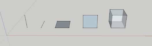
Hybrid Masonry Overview Hybrid masonry was introduced as a structural system concept in 2007. The system is composed of a structural steel frame and reinforced concrete masonry panels. Hybrid masonry offers a design alternative to braced frames and moment-resisting frames that are appropriate for low and mid-rise construction. It is best suited for cases where a structural steel framing system and masonry walls would naturally be chosen due to structural and architectural efficiency. Hybrid masonry includes three distinct types of load transfer, which are shown in Figure 1. In Type I Hybrid Masonry (Figure 1a), steel connectors transfer in-plane shear between the steel frame and the top of the masonry panel. These connectors can be either rigid link plates or ductile fuse plates. The connectors do not transfer any vertical
(a)
load to the masonry wall, but their design can have a significant influence on the overall performance of the system. In Type II and III Hybrid Masonry (Figure 1b and Figure 1c), headed studs are used to transfer shear from the beam and/or columns to the masonry panel. Vertical load is also transferred directly through contact from the beam to the top of the masonry panel. In its simplest form (Type I), hybrid masonry consists of reinforced concrete masonry panels connected to the surrounding steel frame such that story shears can be transferred from the floor beams to the masonry. The masonry panel is constructed in-plane with the steel frame, supported on the floor beam or foundation below the panel. Steel connector plates between the masonry panel and the floor beam above the panel transfer only horizontal story shears (Figure 1a). The masonry does not make contact with the upper beam or columns other than through-bolts in vertically slotted holes in the connector plates, which are designed either as ductile “fuse” or elastic “link” connectors. The structural masonry panel acts as a surrogate-bracing member and can be reinforced both vertically and horizontally to resist in-plane and out of plane lateral forces. Hybrid Masonry Types II and III are designed to transfer both shear and vertical load from the steel beam to the top of the masonry panel and, in the case of Type III, to transfer shear between the panel and the steel columns (Figure 1b and Figure 1c). Shear transfer is achieved through the use of headed studs welded to the beam and columns and embedded in the grouted cells, or formed bond beams, of the concrete masonry panel. All inelastic activity is focused in the masonry panel, while the steel frame and headed studs are designed with an overstrength factor to remain elastic during a design level seismic event.
Lessons Learned problems and solutions encountered by practicing structural engineers
Hybrid Masonry Connections and Through-Bolts
Through-Bolt Connectors The performance of hybrid masonry is highly dependent upon the performance of the connectors. Therefore, much of the research on hybrid masonry
(b)
(c)
Figure 1. Hybrid Masonry Systems: (a) Type I; (b) Type II; (c) Type III.
STRUCTURE magazine
11
By Gaur Johnson, Ph.D., S.E. and Ian Robertson, Ph.D., S.E.
Gaur Johnson is an Assistant Professor at the University of Hawaii at Manoa. Gaur can be reached at gaur@hawaii.edu. Ian Robertson is a Professor of Structural Engineering in the Department of Civil and Environmental Engineering at the University of Hawaii at Manoa. Ian can be reached at ianrob@hawaii.edu.