TECHNOLOGY information and updates on the impact of technology on structural engineering
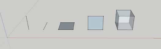
Line elements. | Plate/shell elements. | Solid (brick) element.
S
oftware programs for structural engineers continue to escalate in complexity, as engineers become increasingly reliant on those tools to increase accuracy in analysis and efficiency during design. To solve complex problems efficiently, and to gain a more in-depth understanding of the elements being analyzed, structural engineers are using Finite Element Analysis (FEA). Of course, each of the different FEA programs has their idiosyncrasies, all of which require designers to pay close attention when using these programs. What exactly is finite element analysis? It is the process of reducing (simplifying) a problem with infinite degrees of freedom to a finite number of elements with unique material properties. FEA programs can resolve even the most complex problems in a reasonable amount of time. The process of finite element modeling and analysis is an approximate solution which closely mimics an actual structure in a way that allows structural engineers to design for the stresses, forces, and deflections that are determined using the FEA method. Some of the more commonly used software programs for FEA with masonry design are RAM Elements (soon to be released as STAAD(X) from Bentley Systems, Inc.), as well as RISA Floor and RISA 3D (from RISA Technologies). Other FEA programs with high-end analysis features, such as SCIA Engineer, are important tools for structural engineers because they offer more options for
Finite Element Modeling, Analysis, and Design for Masonry By Samuel M. Rubenzer, P.E., S.E.
Samuel M. Rubenzer is the founder of FORSE Consulting and assists with designs on a variety of projects and building types. He has also been the structural engineering consultant to Structural Masonry Coalitions in several states. He can be reached at sam@forseconsulting.com.
Node Ty Rz Tz
General Comments about Finite Element Modeling Finite element models are created by modeling line, plate/shell, and solid (or brick) elements, with associated end nodes. Complicated three-dimensional elements, such as solid (or brick) elements, are not usually available in most commercial design software. In structural engineering, most problems can be modeled with one-dimensional line elements, or two-dimensional plate or shell elements, and result in reasonably accurate solutions. When creating a model, the line and plate/ shell elements with their associated properties are defined, and the end nodes are defined with translational or rotational degrees of freedom. The properties assigned to the line and plate elements must be defined to associate a reasonable stiffness with each element. Columns and beams (not masonry lintels) can be modeled with line elements, and walls and slabs can be modeled with plate/shell elements. Many software programs allow you to define the geometric boundaries of entire wall panels from movement joint to movement joint (a movement joint is either an expansion joint in brick or control joint in concrete masonry) and discretize those large geometries into smaller finite elements by a process called meshing. Sometimes meshing is a manual process, and other times software programs will offer automatic meshing.
Wall Element
Ry R
creating elements that more closely represent a structural component’s behavior.
Tx
Properties: • Axial • Vertical Bending • Horizontal Bending • Torsion • Vertical Shear • Horizontal Shear
x
Node degrees of freedom and wall element properties.
14 May 2016