11 minute read
acid plant debottlenecking strategies
Feature acid plant debottlenecking strategies
By: Guy Cooper, P. Eng.; Dr. Andres Mahecha-Botero, P. Eng.; Dr. Werner Vorster, P. Eng.; Neal Londry, E.I.T.; NORAM Engineering and Constructors Ltd., Vancouver, Canada.
take advantage of your assets
NORAM receives many requests for strategies to increase the capacity of an acid plant. Each plant has a unique set of debottlenecking solutions which can result in capacity increases between 10-30% or even higher. Compared to the cost of a new acid plant, a plant upgrade taking maximum advantage of existing assets is a much more economical approach. And if equipment needs to be replaced for maintenance reasons, so much the better, because the new equipment can be sized for the target capacity.
Play to your (so2) strengths
One of the first things we ask of a client who is looking for more capacity is to provide us with the current operating data, including SO2 concentrations. A plant operating with an SO2 strength to the first converter pass of, say, 10%, could achieve a 15% increase in capacity by increasing the gas strength to 11.5% SO2. Of course, emissions and heat exchange equipment will need to be assessed and may need upgrades/replacement. Cesiumpromoted and recently introduced highactivity vanadium catalysts make it possible to accommodate increased SO2 loadings within the existing converter. Heat removal from the sulfuric acid loop can be handled with acid side upgrades. More on that later.
Checking the pressure (drops)
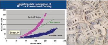
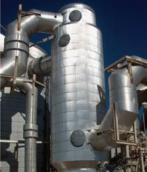
We also ask for recent pressure surveys. Routine pressure surveys (say, monthly) are one of the best ways to track plant performance and equipment condition. Typically, measurements are taken across all gas-side equipment with a digital manometer and recorded with the production rate, blower rate/rpm, and the SO2 strength. In one plant, we found an extremely high pressure drop across a cold gas exchanger due to fouling and the design. A replacement cold exchanger with a hot sweep feature (see Fig. 1) designed for low pressure drop contributed to that plant achieving and maintaining a 20% increase in capacity. In another plant, we identified high pressure drops in the towers and addressed this by upgrading to a low-pressure drop packing (see Fig. 2). Replacing high pressure drop equipment, even if more capacity is not immediately required, will often improve overall plant performance and lower blower energy costs.
Fig. 2: NORaM Hp™ Low pressure Drop Saddle.
Metallurgical acid plant opportunities
Temperature limits for catalysts restrict SO2 concentration to the first pass to a maximum of about 12% with standard catalyst, and 13-14% with cesiumpromoted catalyst operating at a lower inlet gas temperature. Smelters with oxygen enrichment may produce an SO2 gas with up to 30% strength prior to air dilution upstream of the acid plant. NORAM has designed pre-converter systems for such plants, which take a portion of the high strength gas flow, dilute it, then convert two thirds of the SO2 to SO3 which is then removed as acid. The low-concentration SO2 residue gas is mixed with the highstrength gas upstream of the existing acid plant. The preconverter system uses standard processing steps found in every acid plant, including a converter, a gasto-gas heat exchanger, and an absorbing tower. NORAM has designed pre-converter systems to increase capacity by 20-35%.
Blower enhancements
One may be tempted to go out and purchase a bigger blower to increase gas flow through the plant. A word of caution here: pressure drop increases with the square of the flow. So a 20% increase in flow results in a 44% increase in pressure drop corresponding to much larger energy requirements. A large pressure increase may cause mechanical challenges with downstream equipment, in addition to the significant price tag for a full-flow, highhead 200” W.C. (5,000 mm) blower and drivers.
However, there are some blower techniques that we use for modest increases in flow and capacity. For a sulfur burning plant with the blower taking suction on the dry tower, rerouting some ducting can allow the blower to take suction on the air filter and then discharge the air into the dry tower. This arrangement has the advantage of cooler air going into the blower, allowing more air flow for the same horsepower and an increased compression ratio (discharge/ suction pressure), which also improves performance. Flow and corresponding capacity increase of 3-7% are possible for this ducting reconfiguration. There is a slight loss of energy efficiency per ton of sulfur burned because the blower’s heat of compression now is removed by the dry tower acid cooler instead of the waste heat boiler, but the increased production actually results in a net increase in steam produced compared to that produced before the upgrade.
Booster blowers designed for full gas flow and low head, less than 50” W.C. (1250 mm), are sometimes used for increased capacity by supplementing a main blower. They can be located either downstream of an interpass tower (stiffening of the candle housing shell may be necessary) or take suction on the air filter and supplement a blower taking suction on the dry tower. The increased capacity offsets the increased energy operating cost of a second blower.
high pressure drop sulfur furnace and boiler?
For plants where the sulfur furnace and boiler experience a high pressure drop, we have the solution for you: A furnace and boiler bypass system. With this ducting arrangement, a slip stream of cold air bypasses the sulfur furnace (increasing the gas strength and furnace temperature), mixes with the hot furnace gas that bypasses the waste heat boiler, and combines with the main process stream downstream of the boiler. A schematic is shown in Fig. 3.
This simple arrangement gives several benefits. First off, there is a reduced pressure drop which varies to the second power with flow. For example, a 10% bypass results in a 21% reduction in the total furnace/blower pressure drop. If you have a total furnace and boiler pressure drop of 20” W.C. (500 mm), there would be a pressure reduction of 4.2” W.C. (105 mm) for the 10% bypass. For a 2,400 TPD acid plant, this could add 35 TPD of production.
The reduced flow to the sulfur furnaces increases the residence time, which improves sulfur combustion and reduces the chances of uncombusted sulfur. The higher temperature improves the thermal driving force (LMTD) of the boiler, resulting in better heat transfer. The furnace refractory needs to be checked that it can accommodate the higher furnace temperatures.
And as a final benefit, this arrangement may permit replacement of the maintenance-prone jug valve controlling the hot furnace gas split with a stainless-
steel damper controlling a much cooler air/furnace gas stream.
upgrades to the acid system
With an increase in gas flow to the acid towers, more acid flow will often be required, especially for the interpass tower. An increased flow will keep the acid concentration and the acid temperature at the bottom of the tower in the proper range. The good news is that acid side upgrades are relatively inexpensive compared to replacing gas side equipment. Changes here depend on the amount of capacity increase, but can range from simply installing a larger pump impeller to replacing an acid cooler, acid pump, and acid piping.
A new acid distributor may be required for the higher acid flow and if there are blanks on the candle tubesheet, a few more candles may be added to limit pressure drop increase with the higher gas flow. Fortunately, Brownian diffusion candles operate in the laminar flow range and pressure drop only increases linearly with flow. As mentioned earlier, consider low-pressure drop packing so that increases in gas flow do not result in higher tower pressure drops.
your mileage may vary
How much of a capacity increase makes sense for your plant? That raises another question: How much do you plan to spend? For a plant study, we rank the cost of each upgrade option versus the incremental capacity increase, and we compare that to the unit cost of acid produced for a new acid plant.
Your mileage may vary, but we have seen plants increase in capacity by 20-30% economically compared to the capital cost/acid production ($/ton) for a new acid plant. Older plants may have older high-pressure drop equipment which provides more opportunities for easier savings. Newer acid plants often have less maintenance downtime and may require less peripheral equipment to be replaced as part of the upgrade.
And if your plant has frequent shutdowns due to ducting leaks, acid piping leaks, and fouled equipment, improving reliability with new equipment can be a simple
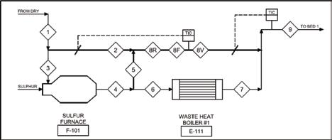
Fig. 3: Schematic of NORaM Furnace Bypass System.
way to increase annual acid and steam production. But that is a topic for another day!
NORAM Engineering and Constructors Limited designs and supplies sulfuric acid plant equipment for improving reliability and capacity. Over the past 30 years, they have performed over 250 acid plant engineering studies. They offer low-pressure drop cold exchangers with hot sweep, low-pressure drop packing, and proprietary furnace bypass systems.
For more information, email sulfuric@noram-eng.com; or contact C. Guy Cooper at gcooper@noram-eng.com or (604) 696-6910. q
Plant Audit
Start-up & plant operation


Construction & commissioning Sulphurnet successfully installed the first fully automatic
Self Cleaning Liquid Sulphur Filter.
E&P Phase
Department PrOdUCT NEWS
sensotech’s Liquisonic® simultaneously monitors gas scrubber liquid and salt in real time
Environmentally harmful, corrosive, or toxic gases are used in many industrial processes. To protect people and the environment, the treatment of these gases is subject to strict regulations, in particular the specific purification criteria a gas scrubber must achieve. Ensuring the complete conversion of toxic components while using scrubbing liquid efficiently is often a challenge for process engineers. The effectiveness of a gas scrubber depends on the exact dosage of the scrubbing liquid, for example, caustic soda.
To enable an exact determination of the concentration of the scrubbing liquid and the salts, two physical measurands have to be combined. Conventional measuring methods often map only one measurand and neglect the influence of the resulting salts. In addition, in many cases the process is monitored in a very time-consuming manner by sampling and titration. The LiquiSonic® process measuring system analyzes concentrations of both the washing liquid and the salt in real time. This allows exact dosing and adjustment of the washing liquid, making the washing process much more efficient and safer. Thanks to the explosion-proof inline measuring system, no intervention in the process is necessary. The exact concentration of the scrubbing liquid and the salt content are available at

The controller reliably displays concentrations of both scrubbing liquid and salt content.
all times. Critical situations in which toxic and environmentally harmful gases could escape can be detected at an early stage by LiquiSonic® and countermeasures can be initiated quickly.
The maintenance-free measuring devices from SensoTech GmbH are very durable and can be easily integrated into the process control system. Automated documentation and various diagnostic tools provide a comprehensive analysis of the process and can be used for further improvements. LiquiSonic® reduces hazards for the environment and employees and ensures efficient, time-saving process analysis.
For three decades, SensoTech GmbH has been involved in the development, manufacture, and sale of inline analysis systems for processes in liquids. Installed worldwide, SensoTech’s high-precision and innovative measuring systems monitor concentrations, compositions, property changes or substance transformations directly in the process. Special calculation methods and highly developed sensor technologies enable reliable and fast measurement results even under difficult process conditions. For more information, visit www. sensotech.com. q


416.444.4880
admin@mercad.com ● www.mercad.com


