
16 minute read
UAV and UGV Autonomous Cooperation for Wildfire Hotspot Surveillance
from PCR - Fall 2022
by Charles Jiang (VI), Diego Pasini (VI), Dr. Marie-Pierre Jolly
Abstract
As wildfires burn millions of acres each year around the globe and have become more severe due to climate change, wildfire prevention is more important now than ever. Existing wildfire surveying techniques such as hotspotting and cold trailing require human interventions that can lead to dangerous situations or satellite imagery which does not provide real time data on hotspots. To address this problem, we propose a low-cost and effective integrated system of robots composed of an unmanned aerial vehicle (UAV, or drone) and unmanned ground vehicle (UGV, or rover) that autonomously cooperate and pathfind to detect and investigate hotspots. The UAV monitors a post-forest fire area from the air and uses aerial footage to create long-term direction for the UGV to inspect specific suspected hotspots. The UGV then follows the path to investigate each hotspot with centimeter-level accuracy. Testing of the pathfinding system with satellite imagery yielded highly accurate and consistent results necessary for high-precision autonomous navigation when investigating hotspots in dynamic environments.
Wildfires have an enormous human, environmental, and economic impact on society. In addition to lost human lives and massive carbon emissions, wildfires cost over $16 billion in damages to structures and fire management alone in the US in 2020 [1]. An essential part of wildfire prevention is identifying hotspots which are loose embers that stem out of a larger fire and light smaller pockets of fire. Currently, hotspotting relies on different techniques: watch towers, firefighters, satellite imagery, and aircraft. Watch towers can be expensive as they require around-the-clock staffing and only provide a limited detection range and angle of view. Firefighters can be deployed to detect hotspots and cold trails, which involves putting their hands in the ground to check for small pockets of embers after the wildfire has died down, but this procedure can lead to dangerous situations and requires extensive human resources. Satellite imagery, albeit precise for hotspot detection, cannot provide real-time data about these hotspots [2]. Finally, aircraft such as helicopters and planes can provide imagery for hotspot detection, but they require space to take off and are expensive to maintain and fly. The solution we investigate in this paper involves the integration of a UAV and UGV into a single autonomous system where the UAV finds a path between suspected hotspots and the UGV investigates them on the ground. The UGV also avoids undetected obstacles using our short-term correction algorithm. Previous research has demonstrated that UAV and UGV cooperative systems are useful for mapping environments and search and rescue [3], [4]. These systems, however, have not been specifically developed to address wildfire prevention through hotspot mapping. II. METHODS
In this paper, we propose a low-cost scalable system of UAVs (drones) and UGVs (rovers) to automate hotspotting. Using a protocol called LDSC (long-term direction, short-term correc tion), a drone flies up and creates a long-term path for the rover based on aerial footage. The rover follows that path and avoids obstacles unidentified by the drone using short-term correction.
Figure 1. Overview of the UAV and UGV Cooperative System
A. System Overview
The system consists of three main components: a drone, a rover, and a ground station, as seen in Fig 1. All devices are connected through a server powered by Apache Kafka to which data and commands are sent [5]. The order of operations for the system is: 1) The drone lifts off, travels to its designated waypoint, and takes a photo of the area in which the rover will be moving. 2) The image is then sent to the ground station which creates a path using a modified pixel weighting A* pathfinding algorithm [6]. The path includes points of interest detected by the drone (suspected hotspots). Each pixel in the path is converted to GPS coordinates. 3) The GPS coordinates are then sent to the rover. The rover follows the path and adjusts to any obstacles overlooked by A* with an obstacle-avoidance algorithm.
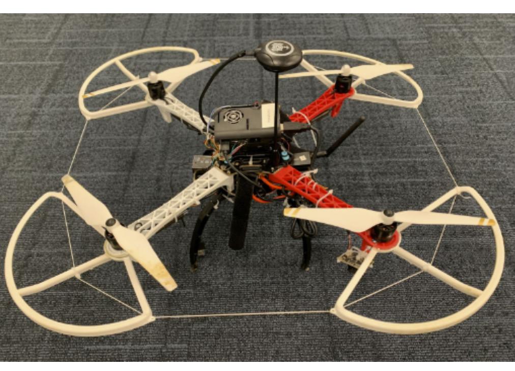
Figure 2. The Drone
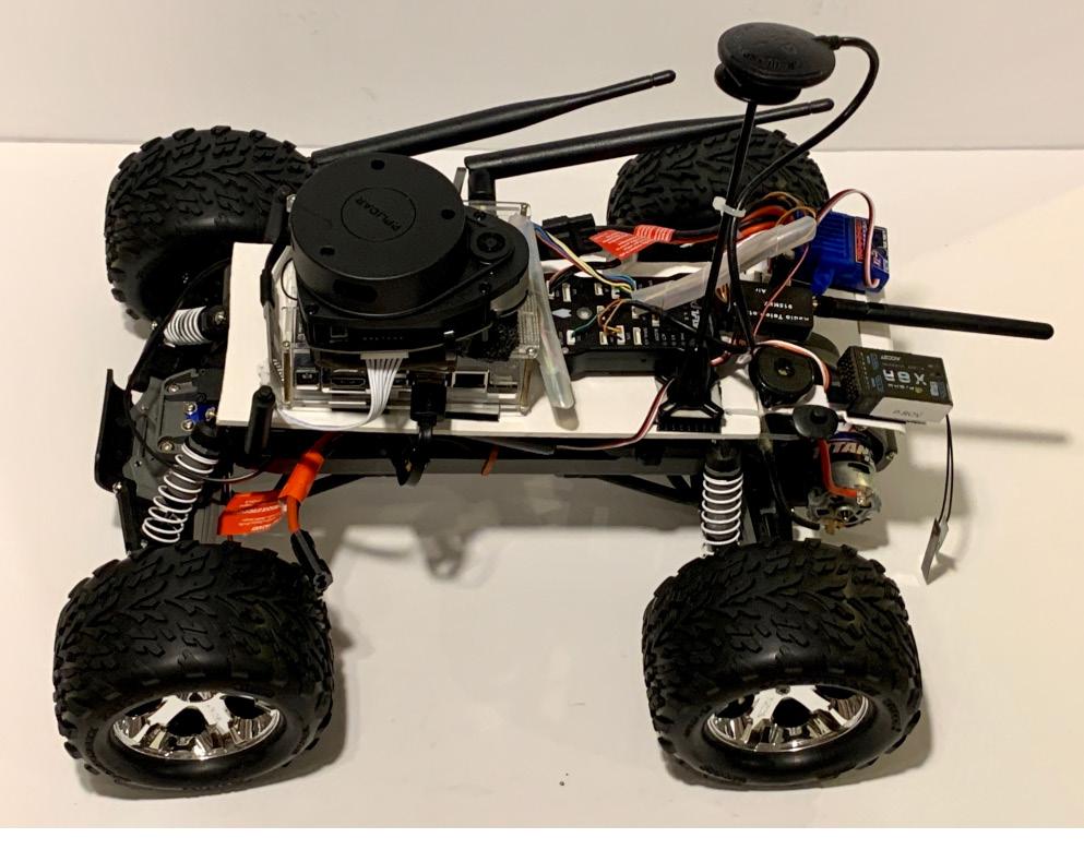
Figure 3. The Rover C. Software
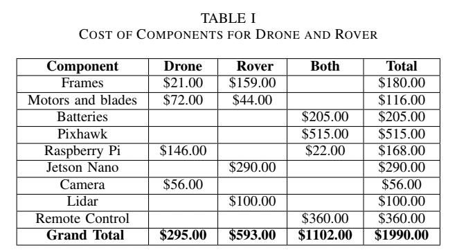
B. Hardware Design
In this paper, we built a drone and rover from scratch as shown in Fig. 2 and Fig. 3. As the drone and rover need to navigate autonomously, make intelligent decisions, and communicate with each other during navigation, the vehicles need to be computationally capable yet physically small. Seen in Fig. 2 and Fig. 3, both the drone and rover use a pixhawk 2.4.8 as the flight controller [7]. Attached companion computers allow for communication, autonomous movement, and computationally heavy tasks. The drone uses a Raspberry Pi 4B+ to minimize weight, while the rover uses a Nvidia Jetson Nano for higher computational power [8], [9]. The vehicles are powered by lithium polymer (LiPo) batteries, and the companion computers are powered by separate USB battery packs. Both vehicles localize themselves using a GPS compatible with an APM serial port. The drone holds a gyroscopic camera gimbal with 9g servos and an Arducam Wide Angle lens camera [10]. The rover is driven by one motor in the back and a servo in the front to steer. It is also equipped with a SlamTec RPLIDAR A1 unit to provide a 2D map of surrounding obstacles [11]. All hardware components were purchased from common marketplaces for less than $2,000, shown in Table I. In total, half of the budget was spent on components usable for both the drone and the rover. A detailed list of components and their costs is available in the Github repository for this article.
The rover and drone use Python 2.7 and several Python libraries, including MAVProxy 1.8.46, DroneKit 2.9.2, OpenCV, and PyGeodesy 22.7.22 [12]–[15]. A startup script launches MAVProxy, which connects to the vehicles’ pixhawks. To begin navigation, DroneKit navigation commands are sent to MAVProxy. Computer vision is handled with OpenCV for camera calibration, the A* pathfinding algorithm, and capturing images, while PyGeodesy helps in the process of converting image pixels to GPS coordinates.
D. Data Communication & Network Software and Design
The drone, rover, and ground station all communicate using Apache Kafka. Each device has a consumer that listens to a topic on a server created on the ground station. Commands are sent by the producers as JSON serializables. After a consumer receives a command that is labeled for its device, it analyzes the command and executes its operations. The device then communicates to its respective producer to send any data back to the topic. Any number of devices can be added to this network using this framework, making the number of vehicles in the system scalable. E. Drone
The drone, shown in Fig. 2, is a quadcopter designed to capture an aerial map of the target area and design a path between hotspots for the rover to follow. Using dronekit and waypoint finding, the drone autonomously flies to a target altitude and GPS coordinates, takes a photo using a gyroscopic camera mount, and sends that photo to the ground station for further processing. 1) Gyroscopic Camera Mount: To ensure accurate conversion of pixels into latitude and longitude coordinates, a 2-axis servo mount is used in conjunction with a mpu6050 to keep the camera facing the ground irrespective of the drone’s movement [16]. During the flight, the program starts a subprocess that perpetually adjusts the x and y-angles of the camera mount to compensate for tilting. 2) Camera Calibration: The drone uses a camera with a wide-angle lens to capture 2D images of the ground. Due to the innate characteristics of a wide-angle lens, optical barrel distortion causes objects in images to appear closer or further apart than they actually are. Distinct from the rest of the system, camera calibration was conducted using the OpenCV checkerboard test in order to undistort images and ensure accurate mapping [17]. Several images of a checkerboard were taken from different viewpoints to estimate distortion coefficients and parameters of the camera. The mean reprojection error, a measure of the calibration’s accuracy, was 0.0459 pixels, well below the value of 1 that typically represents accurate estimations. Images were then able to be undistorted using the estimated distortion coefficients [18]. After taking the undistorted image, the drone waits until it is connected to the Apache Kafka server, converts the image into a bitmap/JSON serializable, and sends the image to the Kafka topic. The drone then returns to its starting waypoint and lands. F. Groundstation
After the ground station’s Apache Kafka consumer receives the image from the drone, the ground station converts the image back into an OpenCV numpy array and performs the A* algorithm to create a path connecting the nodes of interest (i.e. the suspected hotspots). In a further embodiment of this research, existing thermal imaging techniques could be used to detect the exact location of the hotspots, but this example used aerial camera footage and manually selected nodes [19]. 1) A*: A* is a search algorithm that finds the most efficient path between two nodes using a heuristic value (the distance to the end node) and the cost value of moving between each node. The algorithm is run on an image, representing each pixel as a node in the graph with up to eight neighboring nodes. Compared to other algorithms such as Dijkstra, A* is significantly faster. In this version, the cost (c) of moving between nodes is represented as a three-dimensional euclidean distance between the RGB values (each ranging from a value of 0 to 255) of both nodes shown in the equation below:
Weighting pixels based on color is used for the cost of the path, as it provides a way to determine changes in terrain using a visual camera which is more affordable than other sensors such as 3D LIDAR or stereo vision. Us-

ing color as the cost means that the path prioritizes roads and other areas of the map that have similar terrain for the rover to travel on.
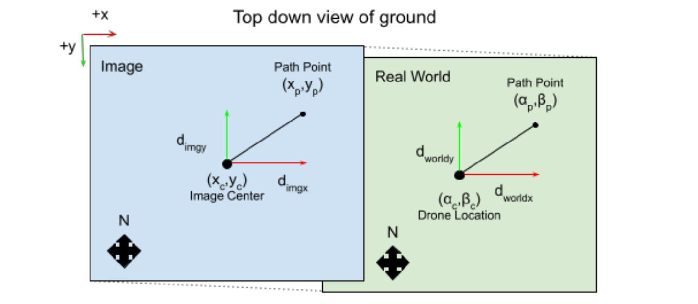
Figure 4. Diagram of pixel to GPS coordinate algorithm: the blue box represents the image plane, the green box represents the real world
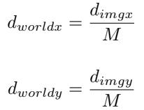
2) Pixel to GPS Coordinates: The center of the image (χc, γc) is taken as the GPS drone location (αc, βc) where α is latitude and β is longitude. The altitude and drone location are known when the image is taken. The degree of the camera mount in relation to the compass of the drone is also known and is used to adjust the heading of the photo to face North. The algorithm to convert a single pixel to GPS coordinate works as follows. First, the pixel distance between (χp, γp) and (χc, γc) is converted into meter based distance dimgx and dimgy as shown in Fig. 4. dimg is calculated by dividing the number of pixels between (χp, γp) and (χc, γc) by the resolution (pixels per meter) of the image. Second, the magnification (M) of the image is calculated with the following formula:
where odist is the height of the drone, and idist is the distance between the lens and the image sensor of the camera. idist is derived from the lens equation: Where f is the focal length, which was estimated during camera calibration. Third, the real-world distance dworldx and dworldy are calculated as shown in Fig. 4.
Finally, the latitude and longitude coordinates (αc, βc) of the pixel are calculated using the Vincenty formula from PyGeodesy which combines computational efficiency and accuracy up to a meter [20]. The NAD83 datum model of Earth’s surface was incorporated to to improve the formula’s accuracy. G. Rover
The rover, shown in Fig. 3, is designed to follow the long-term path and avoid obstacles not seen by the drone. After receiving the GPS path from the ground station, the rover uses dronekit to autonomously travel to coordinates on the path representing the suspected hotspots. 1) Short-Term Correction: As the drone has only one camera and the A* algorithm relies on color, some obstacles on the path may be missed. GPS drift may also cause the rover to deviate from the path. To prevent collisions, an obstacle avoidance protocol based on the bug algorithm was implemented, enabling the rover to avoid objects in the short term before returning to the drone’s long-term path [21]. If the rover’s LIDAR detects an obstacle on the upcoming 2 meters of the path, the rover turns in the direction that brings it closer to the final destination and begins wall-following. Assuming that the final destination of the path is not located inside the obstacle, the rover returns to the long-term path when the path re-emerges from the obstacle. Because leaving the path is dangerous, the conservative design of this protocol ensures that the rover only
launches obstacle avoidance when necessary. III. RESULTS
Tests were conducted on satellite images, but the methods were consistent with the steps outlined above except that the magnification was calculated using Google Earth scale factors.
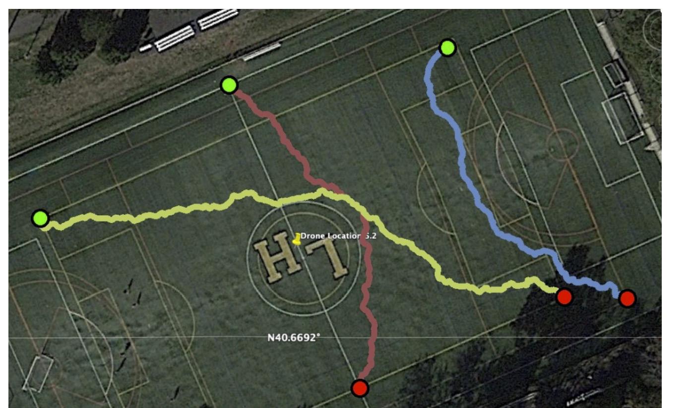
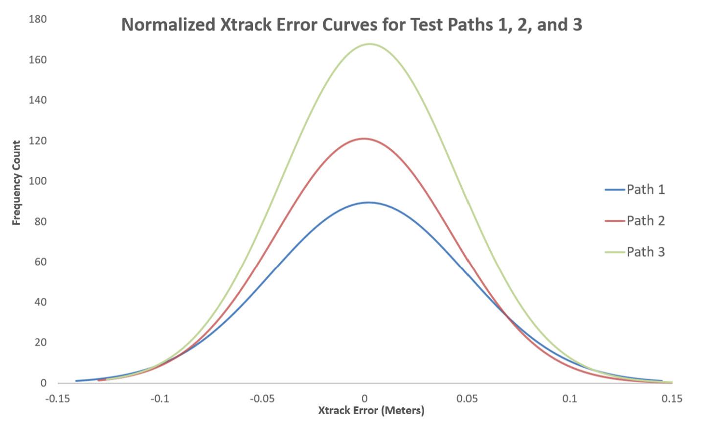
Figure 5. A* Path and GPS path comparison. Left: image of A* path run on satellite image with multiple hotspots as intermediary nodes. Path line thickened for ease of viewing. Right: Image of KML file containing GPA path generated from the path on the left shown in Google Earth. The point of each pin marks a point on the path. Figure 6. The A* results for the three paths tested: green circles represent start points and red circles represent end points
Figure 7. Xtrack Error from the rover following the three different paths
A. A* pathfinding and mapping to GPS coordinates

First, a satellite image was selected to mimic a possible forest fire with dead trees and roads. Three target points labeled hotspots 1, 2, and 3, as seen in the left image of Fig. 5, were manually selected for the rover to investigate. The A* algorithm was then run to generate a path that connects each hotspot, starting with the start node and ending with hotspot 3. The resulting path is shown in the left image of Fig. 5. When there was a clear road, the algorithm tended to stay on it as shown in the first and third parts of the path colored in cyan and magenta. Also, in this test, the color of the brush and ground was difficult to differentiate, resulting in the path crossing the brush. However, it’s important to note that the rover would adjust during navigation using the short-term correction algorithm. Next, the pixel to GPS coordinates algorithm was used to convert the pixel path into GPS coordinates. The coordinates were saved to a KML file, a file to share Google Earth coordinate information, as shown in the right image of Fig. 5. The GPS coordinates form a path that is nearly identical to the original pixel path in the left image of Fig. 5.
B. Rover Path Accuracy
To test the rover’s accuracy in following the A* path, the xtrack error (i.e. the deviation from the desired GPS path in meters) was recorded
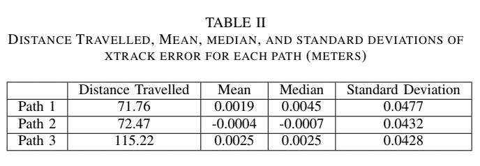
for three new paths of varying lengths and turns shown in Fig. 6. Each path was followed three times by the rover. Path 1 was the shortest and path 3 was the longest, and 400 to 800 data points were measured for each path. Fig. 7 shows the normalized distribution of xtrack errors for each path, and Table II summarizes the key results. As seen in Fig. 7, the xtrack error ranges ±15 cm, with standard deviations below 5 cm across all paths. The small interval of xtrack error shows the rover’s ability to stick to its path consistently despite GPS drift and environmental factors. The fact that the standard deviation in Table II decreases as the path’s length increases reinforces the system’s consistency. IV. CONCLUSIONS AND FUTURE RESEARCH
A system of unmanned drones and rovers cooperating together is an effective solution to investigate hotspots. Due to its low costs (below $2,000 for the entire system), the solution is scalable and could be used to complement human efforts and satellite and aerial surveillance. As seen in the results, the system can create a path from aerial footage, convert it into real-world coordinates, and guide the rover to accurately follow the path. The accuracy and consistency of the system indicate practical applications in high-precision autonomous navigation such as investigating hotspots in a dynamic environment. To view the code created for this project and the indepth parts list, please visit the GitHub link at: https://github.com/IRT-Drover/UAV-and-UGVAutonomous-Cooperation-for-Wild fire-Hotspot-Surveillance Further embodiments of this research could include a drone with more sensors including a thermal camera to implement current imaging techniques to detect the hotspots from an aerial view. The pixel to coordinates algorithm’s accuracy could be improved by using a visual odometry library. The rover needs to be equipped with sensors to determine the severity of a hotspot to prioritize and give information to firefighting organizations. Finally, further testing could be done to increase the number of drones and rovers in the system.
V. ACKNOWLEDGMENTS
We would like to extend our thanks to the Pingry School for funding this project and providing us with useful resources and opportunities. We would also like to thank the past and current members of the Drover project at the Pingry School, in particular, Nicholas Meng, Ayush Basu, and Shaan Lehal. We would also like to thank Olivia Taylor for her support.
Works Cited
[1] M. Wibbenmeyer and A. McDarris, “Wildfires in the United States 101: Context and Consequences,” Resources for the Future, Jul. 30, 2021. https://www. rff.org/publications/explainers/wildfires-in-theunited-states-101-context-and-consequences/ [2] R. Allison, J. Johnston, G. Craig, and S. Jennings, “Airborne Optical and Thermal Remote Sensing for Wildfire Detection and Monitoring,” Sensors, vol. 16, no. 8, p. 1310, Aug. 2016, doi: 10.3390/s16081310. [3] J. Delmerico, E. Mueggler, J. Nitsch, and D. Scaramuzza, “Active Autonomous Aerial Exploration for Ground Robot Path Planning,” IEEE Robotics and Automation Letters, vol. 2, no. 2, pp. 664–671, Apr. 2017, doi: 10.1109/lra.2017.2651163. [4] I. D. Miller, F. Cladera, T. Smith, C. J. Taylor, and V. Kumar, “Stronger Together: Air-Ground Robotic Collaboration Using Semantics,” arXiv:2206.14289 [cs], Jun. 2022, Accessed: Jul. 31, 2022. [Online]. Available: https://arxiv.org/abs/2206.14289#: :text=Stronger%20 Together%3A%20Air%2DGround%20Robotic%20 Collaboration%20Using%20Semantics [5] “Apache Kafka,” Apache Kafka. [Online]. Available: https://kafka.apache.org/documentation/ [6] “Introduction to A*,” theory.stanford.edu. https //theory.stanford.edu/ amitp/GameProgramming/ AStarComparison.html (accessed Jul. 31, 2022). [7] “Pixhawk Overview—Copter documentation,” ardupilot.org. https://ardupilot.org/copter/docs/common-pixhawk-overview.html [8] R. P. (Trading) Ltd, “Raspberry Pi 4 Model B specifications,” Raspberry Pi. [Online]. Available: https:// www.raspberrypi.com/products/raspberry-pi-4-modelb/specifications/ [9] “Jetson Nano Developer Kit,” NVIDIA Developer, Mar. 06, 2019. [Online]. Available: https://developer.
nvidia.com/embedded/jetson-nano-developer-kit [10] “USB Webcam Camera Modules,” Arducam. https://www.arducam.com/usb-board-cameras-uvcmodules-webcams/#wp-block-themeisle-blocks-advanced-columns-1d97200c (accessed Aug. 01, 2022). [11] “RPLIDAR A1 Low Cost 360 Degree Laser Range Scanner Development Kit User Manual Model: A1M8,” 2016. [12] “MAVProxy — MAVProxy documentation,” ardupilot.org. https://ardupilot.org/mavproxy/#: :text=MAVProxy%20is%20a%20fully%2Dfunctioning (accessed Jul. 31, 2022). [13] ”Welcome to DroneKit-Python’s documentation!,” dronekit python.readthedocs.io. https://dronekit-python.readthedocs.io/en/latest/ (accessed Jul. 31, 2022). [14] “OpenCV: OpenCV modules,” docs.opencv.org. https://docs.opencv.org/4.x/ (accessed Jul. 31, 2022). [15] “PyGeodesy,” mrjean1.github.io. https://mrjean1. github.io/PyGeodesy/ (accessed Jul. 31, 2022). [16] “MPU-6000 and MPU-6050 Register Map and Descriptions Revision 4.2 MPU-6000/MPU-6050 Register Map and Descriptions,” 2013. [17] “OpenCV: Camera Calibration,” docs.opencv.org. https://docs.opencv.org/4.x/dc/dbb/tutorial py calibration.html (accessed Jul. 31, 2022). [18] “Reprojection error,” https://support.pix4d.com/. https://support.pix4d.com/hc/en-us/arti cles/202559369-Reprojection-error (accessed Jul. 31, 2022). [19] A. Viseras, J. Marchal, M. Schaab, J. Pages, and L. Estivill, “Wildfire Monitoring and Hotspots Detection with Aerial Robots: Measurement Campaign and First Results.” [20] C. V. www.movable-type.co.uk , “Vincenty solutions of geodesics on the ellipsoid in JavaScript — Movable Type Scripts,” www.movabletype.co.uk. http://www.movable-type.co.uk/scripts/latlong-vincenty.html (accessed Jul. 31, 2022). [21] Howie Choset, K. M. Lynch, and S. Hutchinson, Principles of robot motion: theory, algoritms, and implementations. Cambridge, Mass. Bradford, 2005. Accessed: Jul. 31, 2022. [Online]. Available: https://www. scholars.northwestern.edu/en/publications/principles-of-robot-motion-theory-algorithms-and-implementations


