25 minute read
Table 6-10 Parameter description
Parameter Description
You can select General or Event.
● General means the system takes snapshot as scheduled
Snapshot type
Image Size
Quality
Interval
HeatMap in Jpeg
Step 4 Click Save
● Event means snapshot functions when video\audio detection, event or alarm is triggered.
The same resolution with main stream.
Snapshot quality. The bigger the value, the better the snapshot quality.
Snapshot frequency.
Select Customized to manually configure snapshot frequency.
When you select channel 2, you can configure this parameter. Select the checkbox and snapshots of thermal images will carry the temperature-measurement information.
6.1.2.3 Configuring Video Overlay
Configure overlay information, and it will be displayed on the Live page.
6.1.2.3.1 Configuring Privacy Masking
You can enable this function when you need to protect the privacy of some area on the image.
Step 1 Select Setting > Camera > Video > Overlay
Step 2 Select the channel
● Select 1 in Channel to configure the parameters for the visible channel.
● Select 2 in Channel to configure the parameters for the thermal channel.
Step 3 Click the Privacy Masking tab.
Step 4 Select the Enable checkbox, drags the corners of the blocks to adjust the block size, and then drag the block to the area that you need to cover.
Click Remove All to delete all the area boxes; you can also just select one box, and click Delete or right-click to delete it.
Step 5 Click Save.
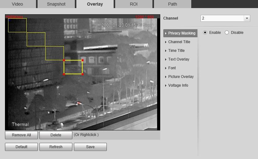
6.1.2.3.2 Configuring Channel Title
You can enable this function if you need to display Channel title in the video image.
Step 1 Select Setting > Camera > Video > Overlay.
Step 2 Select the channel
● Select 1 in Channel to configure the parameters for the visible channel.
● Select 2 in Channel to configure the parameters for the thermal channel.
Step 3 Click Channel Title
Step 4 Select the Enable checkbox, and then enter channel title. The title displays in the video image.
You can drag the Channel Title box on the video image with your mouse to adjust the location of the box.
Step 5 Click Save
6.1.2.3.3 Configuring Time Title
You can enable this function if you need to display time on the video image.
Step 1 Select Setting > Camera > Video > Overlay
Step 2 Select the channel
● Select 1 in Channel to configure the parameters for the visible channel.
● Select 2 in Channel to configure the parameters for the thermal channel.
Step 3 Click Time Title.
Step 4 Select the Enable checkbox, and the time is displayed on the video image.
Step 5 Click Week Display, and then the week information is displayed on the video image.
You can drag the Time Title box on the video image with your mouse to adjust the box’s location.
Step 6 Click Save.
6.1.2.3.4 Configuring Text Overlay
You can enable this function if you want to display words on the video image.
Text Overlay and Picture Overlay cannot work at the same time.
Step 1 Select Setting > Camera > Video > Overlay

Step 2 Select the channel
● Select 1 in Channel to configure the parameters for the visible channel.
● Select 2 in Channel to configure the parameters for the thermal channel.
Step 3 Click Text Overlay.
Step 4 Select the Enable checkbox, and then enter text as needed. Then select the text align method, and the Text Overlay box is displayed on the video image.
You can drag the Text Overlay box on the video image with your mouse to adjust the location of the box.
Step 5 Click Save.
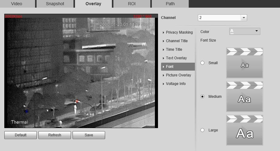
6.1.2.3.5 Configuring Font
You can adjust size and color of the font on the video images based on your own needs.
Step 1 Select Setting > Camera > Video > Overlay

Step 2 Select the channel
● Select 1 in Channel to configure the parameters for the visible channel.
● Select 2 in Channel to configure the parameters for the thermal channel.
Step 3 Click the Font tab.
Step 5 Click Save.
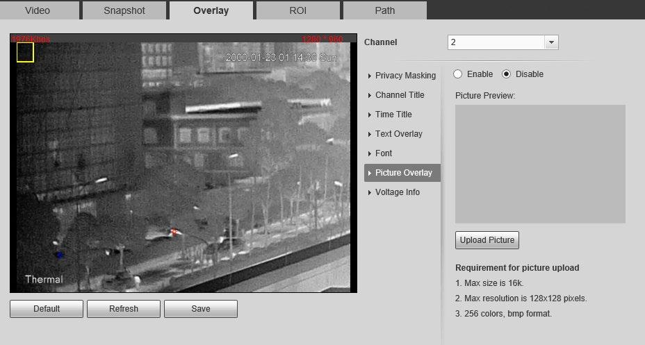
6.1.2.3.6 Configuring Picture Overlay
You can enable this function if you need to display picture information on the video image.
Text overlay and picture overlay cannot work at the same time.
Step 1 Select Setting > Camera > Video > Overlay
Step 2 Select the channel
● Select 1 in Channel to configure the parameters for the visible channel.
● Select 2 in Channel to configure the parameters for the thermal channel.
Step 3 Click the Picture Overlay tab.
Step 4 Select the Enable checkbox.
You will be informed that OSD information is to be closed. Click Save
Step 5 Click Upload Picture, and select a picture. The picture is displayed in video images.
You can drag the Picture Overlay box in the video image with your mouse to adjust the box’s location.
Step 6 Click Save
6.1.2.3.7 Configuring Voltage Information
After enabling this function, the voltage information will be displayed on the image when the camera voltage is abnormal.
Step 1 Select Setting > Camera > Video > Overlay.
Step 2 Select the channel
● Select 1 in Channel to configure the parameters for the visible channel.
● Select 2 in Channel to configure the parameters for the thermal channel.
Step 3 Click the Voltage Info tab.
Step 4 Select On.
The picture overlay function will be disabled after the voltage information function is enabled.
Step 5 Click Save
When the camera voltage is abnormal, the voltage information will be displayed om the image.
For example, for a Camera requires 12V voltage, when the voltage exceeds± 15%, the abnormal voltage information will be displayed on the image, prompting the customer to check the voltage.
6.1.2.4 Configuring ROI
Select ROI in the image, and then the selected image would display with configured quality.
Step 1 Select Setting > Camera > Video > ROI
Step 2 Select the channel
● Select 1 in Channel to configure the parameters for the visible channel.
● Select 2 in Channel to configure the parameters for the thermal channel.
Step 3 Select the Enable checkbox.
Step 4 Hold the left mouse button to draw a ROI area on video images. You can also configure the display quality OF ROI.

● You can draw at most four ROI areas.
● Click Remove All to delete all the area boxes; you can also just select one box, and click Delete or right-click to delete it.
Step 5 Click Save
6.1.2.5 Configuring Storage Path
Configure storage paths covering Live Snapshot, Live Record, Playback Snapshot, Playback Download, Video Clips, and Heat Map

Step 1 Select Setting > Camera > Video > Path
Figure 6-23 Storage path
Step 2 Click Browse, and configure storage paths of live snapshot, live record, playback snapshot, playback download, video clips, and heat map.

Table 6-11 Storage path description
Path Description
Live Snapshot
Live Record
Live snapshot refers to the snapshot of live page.
C:\Users\admin\WebDownload\LiveSnapshot is the default path.
Live record refers to the recorded video of live page.
C:\Users\admin\WebDownload\LiveSnapshot is the default path.
Path Description
Playback Snapshot
Playback Download
Video Clips
Heat Map
Playback snapshot refers to the snapshot of playback page.
C:\Users\admin\WebDownload\LiveSnapshot is the default path.
Playback download refers to the downloaded video of playback page.
C:\Users\admin\WebDownload\LiveSnapshot is the default path.
Video clips refer to the clipped video of playback page.
C:\Users\admin\WebDownload\LiveSnapshot is the default path.
Heat map comes from the location Setting > Temperature.
C:\Users\admin\WebDownload\LiveSnapshot is the default path.
Administrator in the default path is the user account.
Step 3 Click Save
6.1.3 Configuring Audio Parameters
Configure audio parameters covering Encode Mode, Sampling Frequency, Audio in Type, and Noise Filter
Functions of different cameras might vary.
Step 1 Select Setting > Camera > Audio.
Step 2 Configure Audio parameters.
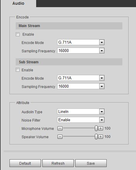
Parameters Description
Enable
Audio can be enabled only when video is enabled. Enable Main Stream or Sub Stream, and the network stream is composed of both audio and video streams. If you do not select Main Stream or Sub Stream, then only video images are transmitted.
Encode Mode
Sampling Frequency
Audioin Type
You can select audio encode mode. G.711A, G.711Mu, and AAC are included.
The configured audio encode mode applies to audio and intercom.
Audio’s sampling frequency. 8K and 16K are included.
Two audio types are selectable.
● LineIn: External audio input source is required.
● Mic: External audio input source is not required.
Noise Filter Enable this function, and the system auto filters ambient Noise.
Parameters Description
Microphone Volume
Adjusts microphone volume.
This function is available on select models.
Adjusts speaker volume.
Speaker Volume
Step 3 Click Save.
This function is available on select models.
6.2 Configuring Network
6.2.1 Configuring TCP/IP
You can configure IP address, DNS (Domain Name System) server and so more according to network planning.
Prerequisites
You have connected the Camera to network.
Procedure
Step 1 Select Setting > Network > TCP/IP.
Step 2 Configure TCP/IP parameters.

Table 6-13 TCP/IP parameters
Parameter Description
Host Name
Enter the host name, 15 characters at most.
Ethernet Card Wire (Default) is set by default.
● Static: You need to manually configure IP Address, Subnet Mask and Default Gateway.
Mode
● DHCP: Obtains IP address automatically. With DHCP enabled, IP Address, Subnet Mask and Default Gateway cannot be configured. You can check the current IP address whether the DHCP takes effect or not.
MAC Address Host’s MAC address, cannot be modified.
IP Version Select IPv4 or IPv6.
IP Address Enter the IP address and subnet mask according to your own needs.
Subnet Mask
All the IPv6 addresses will be validated, so ensure IP address and subnet mask are in the same network segment, which means the front parts of the IP address and the default gateway are the same one.
Default Gateway
Configure it as needed, the default gateway must be in the same network segment with the IP address.
Preferred DNS IP address of the preferred DNS.
Alternate DNS IP address of the alternate DNS.
Parameter Description
Select the checkbox, get the camera MAC address, and then you can modify and configure the camera IP address with ARP/ping command. It is enabled by default. During restarting, you will have no more than two minutes to configure the camera IP address with a ping packet which has certain length. The server will be turned off in 2 minutes, or it will be turned off immediately after IP address configuration. If it is not enabled, the IP address cannot be configured with ping packet. A demonstration of configuring IP address with ARP/Ping.
To obtain a free IP address, you need to ensure that the Camera and your PC are in the same LAN.
Get MAC address from the Camera label.
Open command editor on your PC and enter the following command.
Enable ARP/Ping to set IP address service.

Restart through power or network. Check your PC command line. If there is information such as "Reply from 192.168.0.125…", you have done configuration successfully. Turn it off then.
Enter http://(IP address) in the browser address bar to log in.
Step 3 Click Save.
6.2.2 Configuring Port
Configure the port numbers and the maximum number of users (includes web, platform client, and mobile phone client) that can connect to the device simultaneously.
Step 1 Select Setting > Network > Port
Step 2 Configure parameters.
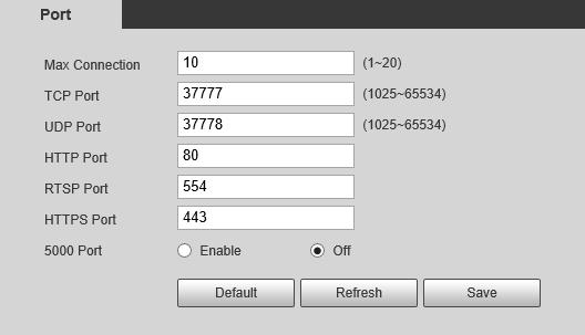
● 0–1024, 1900, 3800, 5000, 5050, 9999, 37776, 37780–37880, 39999, 42323 are occupied for specific uses.
● Do not use the same value of any other port during port configuration.
Parameter Description
Max Connection
The maximum number of users (web client, platform client or mobile phone client) that can connect to the Camera simultaneously, the value is 10 by default.
TCP Port Port of transmission control protocol. The value is 37777 by default.
UDP Port User datagram protocol port, the value is 37778 by default.
HTTP Port
HTTP communication port. The default value is 80. If you have modified the default value, when logging in through a browser, you need to add the latest port number to the end of IP address.
Parameter Description
● 554 is the default port number. If you play live view through Apple’s QuickTime or VLC, the following format is available. This function is also available for Blackberry.
● When the URL format requiring RTSP, you need to specify channel number and bit stream type in the URL, and also user name and password if needed.
● When playing live view with Blackberry smart phone, you need to turn off the audio, and then set the code mode to H.264B and resolution to CIF.
RTSP Port
● Username: admin, for example.
● password rtsp://ip:port/cam/realmonitor?channel=1&subtype=0
● IP: your Camera IP.
● Port: leave it if the value is 554 by default.
● Channel 1: Channel number, starts from 1. For example, if you are using channel 2, then the channel=2.
● Subtype refers to Bit stream type; 0 means main stream (Subtype=0) and 1 means sub stream (Subtype=1).
HTTPS Port Real Time Messaging Protocol. The port that RTMP provides service. It is 1935 by default.
HTTPS Port HTTPS communication port. It is 443 by default.
5000 Port The service port for Windows XP. It is Off by default.
Step 3 Click Save.
The configuration of Max Connection takes effect immediately, and others will take effect after restart the Camera.
6.2.3 Configuring PPPoE
Point-to-Point Protocol over Ethernet, is one of the protocols that device uses to connect to the internet. Get the PPPoE username and password from the internet service provider, and then set up network connection through PPPoE, the camera will acquire a WAN dynamic IP address.
● The Camera has connected to the network.
● You have gotten the account and password from Internet Service Provider.
Step 1 Select Setting > Network > PPPoE.
Step 2 Select the Enable checkbox, and then enter the user name and password.
● Disable UPnP while using PPPoE to avoid possible influence.
● After making PPPoE connection, the camera IP address cannot be modified through web page.
Step 3 Click Save.
The successful prompt displays, and then the real-time WAN IP address is displayed. You can visit the Camera through this IP address.
6.2.4 Configuring DDNS
Properly configure DDNS, and then the domain name on the DNS server matches your IP address and the matching relation refreshes in real time. You can always visit the Camera with the same domain name no matter how the IP address changes.
Prerequisites
Check the DNS server types that the Camera supports.
● Third party server might collect your device information after DDNS is enabled.
● Register and log in to the DDNS website, and then you can view the information of all the connected devices in your account.
Procedure
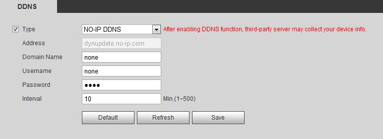
Step 1 Select Setting > Network > DDNS.
Step 2 Select the Type checkbox, and then configure the parameters as needed.
Parameter Description
Type
See the name and web site of DDNS service provides below:
Parameter Description
● "members.dyndns.org" is the IP address of Dyndns DDNS.
Address
Domain name
● "dynupdate.no-ip.com" is the IP address of NO-IP DDNS.
● "members.3322.org" is the IP address of CN99 DDNS.
The domain name that you registered on the DDNS website.
User name Enter the user name and password that you got from DDNS service provide. You need to register an account (with user name and password) on the DDNS service provides’ website.
Password
Update period
Step 3 Click Save
The update cycle of the connection between your Camera and the server. 10 minutes are set by default.
Open your browser, and type the domain name into address bar. Press Enter. If a web page is displayed, the configuration is finished successfully.
6.2.5 Configuring SMTP
Configure SMTP (Email) parameter and enable email linkage. The system sends email to the defined address when the corresponding alarm is triggered.
Step 1 Select Setting > Network > SMTP (Email).
Step

Table 6-16 SMTP (Email) parameter description
Parameter Description
SMTP Server SMTP server address
Port The port number of the SMTP server.
Username The account of SMTP server.
Password The password of SMTP server.
For details, see Table 6-17
Anonymous Select the ckeckbox, and the sender's information is not displayed in the email.
Sender Sender’s email address.
Select from None, SSL and TLS.
Encryption Type
For details, see Table 6-17
Subject
Enter maximum 63 characters in Chinese, English, and Arabic numerals. Click + to select title type, including Device Name, Device ID, and Event Type, and you can set maximum 2 titles.
Attachment Select the checkbox to support attachment in the email.
● Receiver’s email address. Supports 3 addresses at most.
Receiver
● After entering the receiver's email address, the Test button is display. Click Test to test whether the emails can be sent and received successfully.
Health Mail
The system sends test mail to check if the connection is successfully configured. Click the checkbox and configure the Sending Interval, and then the system sends test mail as the set interval.
For the configuration of major mailboxes, see Table 6-17
Table 6-17
Description of major mailbox configuration
Step 3 Click Save to save the configuration.
Step 4 Click Test to test whether the email works normally.
6.2.6 Configuring UPnP
UPnP (Universal Plug and Play) is a protocol that establishes mapping relation between local area and wide area networks. This function enables you to visit local area device through wide area IP address.
Prerequisites
● Make sure that the UPnP service is installed in the system.
● Log in to the router, and configure WAN IP address to set up internet connection.
● Enable UPnP in the router.
● Connect your Camera to the LAN port of the router.
● Set IP address of your router as that of your Camera, or select DHCP to obtain IP address
Procedure
Step 1 Select Setting > Network > UPnP
Step 2 Select the Enable checkbox.
Step 3 Select the mode, and service name in the port mapping list. UPnP can be classified as custom mode and default mode.

● Select Custom, click , and then you can change external port as needed.
● Select Default, and then the system finishes mapping with unoccupied port automatically, and you cannot edit mapping relation.
Step 4 Click Save.
Type "http://external network IP address: external port number" to access Cameras in Intranet whose ports correspond to your router.
6.2.7 Configuring SNMP

SNMP (Simple Network Management Protocol), which can be used to enable software such as MIB Builder and MG-SOFT MIB Browser to connect to the Camera and manage and monitor the Camera.
Prerequisites
● Install SNMP monitoring and managing tools such as MIB Builder and MG-SOFT MIB Browser.
● You can contact technical support for the MIB file that matches the current version.
Procedure
Step 1 Select Setting > Network > SNMP
Step 2 Select SNMP version to enable SNMP.
● Select V1, and the system can only process information of V1 version.
● Select V2, and the system can only process information of V2 version.
● Select V3, and then V1 and V2 become unavailable. You can configure username, password and authentication type. It requires corresponding username, password and authentication type to visit your device from the server.

Using V1 and V2 might cause data leakage, and V3 is recommended.
Step 3 In Trap Address, enter the IP address of the PC that has MIB Builder and MG-SOFT MIB Browser installed, and leave other parameters to the default.
Parameter
SNMP Port
Table 6-18 SNMP parameter description
Description
The listening port of the software agent in the device.
The read and write community string that the software agent supports.
Read Community, Write Community
You can enter number, letter, underline and dash to form the name. Trap Address
The target address of the Trap information sent by the software agent in the device.
Parameter Description
Trap Port
Keep Alive
Result
Read-only Username
The target port of the Trap information sent by the software agent in the device.
Select the checkbox, and then set the period. During the configured period, the system checks whether the camera is online.
Set the read-only username accessing device, and it is public by default.
You can enter number, letter, and underline to form the name.
Set the read/write username access device, and it is private by default.
Read&Write Username
You can enter number, letter, and underline to form the name.
Authentication Type You can select from MD5 and SHA. It is MD5 by default.
Authentication Password It should be no less than 8 digits.
Encryption Type It is CBC-DES by default.
Encryption Password It should be no less than 8 digits.
Step 4 Click Save.
View device configuration through MIB Builder or MG-SOFT MIB Browser.
1. Run MIB Builder and MG-SOFT MIB Browser.
2. Compile the two MIB files with MIB Builder.
3. Load the generated modules with MG-SOFT MIB Browser.
4. Enter the IP address of the device that you need to manage in the MG-SOFT MIB Browser, and then select version to search.
5. Unfold all the tree lists displayed in the MG-SOFT MIB Browser, and then you can view the configuration information, video channel amount, audio channel amount, and software version.
Use PC with Windows and disable SNMP Trap service. The MG-SOFT MIB Browser will display prompt when alarm is triggered.
6.2.8 Configuring Bonjour
Enable this function, and the OS and clients that support Bonjour would find the Camera automatically. You can have quick visit to the Camera with Safari browser.
Bonjour is enabled by default.
Step 1 Select Setting > Network > Bonjour.
Step 2 Select the Enable checkbox, and then configure the server name.
Step 3 Click Save
Result
In the OS and clients that support Bonjour, follow the steps below to visit the network camera with Safari browser.
1. Click Show All Bookmarks in Safari.
2. Enable Bonjour. The OS or client automatically detects the network cameras with Bonjour enabled in the LAN.
3. Click the camera to visit the corresponding web page.
6.2.9 Configuring Multicast
When multiple users are viewing the device video image simultaneously through network, it might fail due to limited bandwidth. You can solve this problem by setting up a multicast IP (224.0.1.0–238.255.255.255) for the Camera and adopt the multicast protocol.
Procedure
Step 1 Select Setting > Network > Multicast
Figure 6-34 Multicast
Step 2 Select the channel
● Select 1 in Channel to configure the parameters for the visible channel.
● Select 2 in Channel to configure the parameters for the thermal channel.
Step 3 Select Enable, and then enter IP address and port number.
Table 6-19 Multicast
Parameter Description
Multicast Address
Port
The multicast IP address of Main Stream/Sub Stream is 224.1.2.4 by default, and the range is 224.0.0.0–239.255.255.255.
The multicast port of corresponding stream: Main Stream: 40000; Sub Stream1: 40016; Sub Stream2: 40032, and all the range is 1025–65500.
Step 4 Click Save, and the login page is displayed. The configuration finishes.

Result
On the Live page, select RTSP in Multicast, and then you can view the video image with multicast protocol.
6.2.10 Configuring Auto Registration
After you enable this function, when the Camera is connected into Internet, it will report the current location to the specified server which acts as the transit to make it easier for the client software to access the Camera.
Step 1 Select Setting > Network > Auto Register.
Step 2 Select the Enable checkbox.
Step 3 Set auto registration parameters.
Parameter
IP Address
Description
IP address or domain name to which the camera transmits its location.
Port The port for auto registration.
Sub-Camera ID Your Camera ID given by the server.
Step 4 Click Save
6.2.11 Configuring 802.1X
802.1X can control the Camera’s access to LAN.
Step 1 Select Setting > Network > 802.1x.

Step 2 Select the Enable checkbox.
Step 3 Set 802.1x parameters.
Parameter Description
Authentication PEAP (protected EAP protocol).

Username The username that was authenticated on the server.
Password Password of your username.
Step 4 Click Save
6.2.12 Configuring QoS
You can solve problems such as network delay and congestion with this function. It helps to assure bandwidth, reduce transmission delay, packet loss rate, and delay jitter to improve experience. 0–63 means 64 degrees of priority; 0 for the lowest and 63 the highest.
Step 1 Select Setting > Network > QoS
Step 2 Set QoS parameters.
Parameters
Real-time Monitor
Command
Step 3 Click Save.
Description
Configure the priority of the data packets that used for network surveillance. 0 for the lowest and 63 the highest.
Configure the priority of the data packets that used for configure or checking.
6.2.13 Platform Access
6.2.13.1 P2P
P2P (peer-to-peer) technology enables users to manage devices easily without requiring DDNS, port mapping or transit server.
Scan the QR code with your smart phone, and then you can add and manage more devices on the mobile phone client.
Step 1 Select Setting > Network > Access Platform > P2P
● When P2P is enabled, remote management on device is supported.
● When P2P is enabled and the device accesses to the network, the status shows online. The information of the IP address, MAC address, device name, and device SN will be collected. The collected information is for remote access only. You can cancel the Enable selection to reject the collection.

Step 2 Log in to mobile phone client and tap Device management
Step 3 Tap + at the upper-right corner.
Step 4 Scan the QR code on the P2P page.
Step 5 Follow the instructions to finish the settings.
6.2.13.2 ONVIF
The ONVIF verification is enabled by default, which allows the network video products (including video recording device and other recording devices) from other manufacturers to connect to your device.
ONVIF is enabled by default.
Step 1 Select Setting > Network > Access Platform > ONVIF
Step 2 Select On
Step 3 Click Save.
Through RTMP, you can access the third-party platform (such as Ali and YouTube) to realize video live view.
● RTMP can be configured by admin only.
● RTMP supports the H.264, H.264 B and H.264H video formats, and the AAC audio format only.
Step 1 Select Setting > Network > Access Platform > RTMP
Step 2 Select the Enable checkbox.
Make sure that the IP address is trustable when enabling RTMP.
Step 3 Configure RTMP parameters.
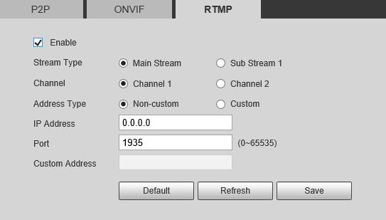
Table 6-23 Description of RTMP parameters
Parameter Description
Stream Type
Address Type
IP Address
Port
Custom Address
Step 4 Click Save.
6.3 Storage
The stream for live view. Make sure that the video format is the H.264, H.264 B and H.264H, and the audio format is AAC.
Includes Non-custom and Custom
● Non-custom: Enter the server IP and domain name.
● Custom: Enter the path allocated by the server.
When selecting Non-custom, you need to enter server IP address and port.
● IP address: Support IPv4 or domain name.
● Port: We recommend that you use the default one.
When selecting Custom, you need to enter the path allocated by the server.
The system can link record channel when an alarm event occurs. After alarm, the system stops recording after an extended time period according to the Record Delay setting.
To use the record linkage function, set record plan for motion detection alarm and enable auto recording in record control.
6.3.1 Configuring Schedule
6.3.1.1 Configuring Record Plan
After the corresponding alarm type (Normal, Motion, or Alarm) is enabled, the record channel links recording.
Step 1 Select Setting > Storage > Schedule > Record
Step 2 Select the channel
● Select 1 in Channel to configure the parameters for the visible channel.
● Select 2 in Channel to configure the parameters for the thermal channel.
Step 3 Set record plan.
Green represents normal record plan (such as timing recording); yellow represents motion record plan (such as recording triggered by intelligent events); red represents alarm record plan (such as recording triggered by alarm-in).
● Method one: Select a record type, such as Normal, and directly press and drag the left mouse button to set the time period for normal record on the timeline.
● Method two: Enter an actual time period.
1. Click Setting next to a day.
Figure 6-42 Setting (record time period)
2. Select a day, and the alarm type next to a period, and then set the period.
◇ Select All or checkboxes of some days to set the time period of multiple days at one time.

◇ You can set 6 time periods per day.
Step 4 Click Save.
6.3.1.2 Configuring Snapshot Plan

According to the configured snapshot plan, the system enables or disables snapshot at corresponding time.
Step 1 Select Setting > Storage > Schedule > Snapshot
Step 2 Select the channel
● Select 1 in Channel to configure the parameters for the visible channel.
● Select 2 in Channel to configure the parameters for the thermal channel.
Step 3 Select snapshot type and set time period.
Green represents normal snapshot plan (such as timing snapshot); yellow represents motion snapshot plan (such as snapshot triggered by intelligent events); red represents alarm snapshot plan (such as snapshot triggered by alarm-in).

● Method one: Select snapshot type, such as Normal, and directly press and drag the left mouse button to set time period for normal snapshot on the timeline.
● Method two: Enter an actual time period.
1. Click Setting next to a day.
2. Select a day, and the alarm type next to a period. Then set the period.
◇ Select All or checkboxes of some days to set the time period of multiple days at one time.

◇ You can set 6 time periods per day.
3. You can set 6 time periods per day.
Step 4 Click Save
6.3.1.3 Configuring Holiday Schedule
Select a day as the holiday and video recording and snapshots will be enabled on the holiday.
● To use holiday recording function, you need to configure holiday recording schedule. For details, see "6.3.1.1 Configuring Record Plan".
● To use holiday snapshot function, you need to configure holiday record and snapshot schedule. For details, see "6.3.1.2 Configuring Snapshot Plan"
Step 1 Select Setting > Storage > Schedule > Holiday Schedule.
Step 2 Select from record and snapshot.
Step 3 Select days that you need, and then set them as the holiday. Those days with yellow color indicates that they were set as holidays.

6.3.2 Configuring Storage Method
6.3.2.1 Configuring Storage Path
You can set the storage methods of video recording and snapshot according to event types. You can save them in SD card, FTP or NAS.
Local storage is available only on models that support SD card.
Step 1 Select Setting > Storage > Destination > Path.
Step 2 Select different storage paths for the recorded videos and snapshots which belong to different event types.
Table 6-24 Path parameters
Parameter Description
Event type Select from Scheduled, Event and Alarm


Local Save in the internal SD card.
FTP Save in the FTP server.
NAS Save in the NAS (network attached storage).
Step 3 Click Save
6.3.2.2 Configuring Local Storage
Displays the information of the local SD card. You can set it as read only or read & write; you can also hot swap and format SD card.
Select Setting > Storage > Destination > Local
● Click Read Only, and then the SD card is set to read only.
● Click Read & Write, and then the SD card is set to read & write.
● Click Hot Swap, and then you can pull out the SD card.
● Click Refresh, and then you can format the SD card.
● Click Format, and you can format the SD card.
6.3.2.3 Configuring FTP Server
FTP can be enabled only when it was selected as a destination path. When the network does not work, you can save all the files to the internal SD card for emergency.
Step 1 Select Setting > Storage > Destination > FTP.
Step 2 Select the Enable checkbox, and then select the service type.
Select FTP or SFPT from the drop-down list. SFTP is recommended to enhance network security.
Step 3 Configure FTP parameters.
Parameter Description
Server Address The IP address of the SFTP or FTP server.

Port The port of the SFTP or FTP server.
User name The username to log in to the server.
Password The password to log in to the server.
Remote Directory The destination path in to the server.
Emergency (Local) Select the Emergency (Local) checkbox, and when the FTP server does not work, all the files are saved to the internal SD card.
Step 4 Click Save. Click Test to check whether the server has been properly connected.
6.3.2.4 Configuring NAS Server
This function can be enabled only when NAS has been selected as destination path. Click the NAS tab and you can save files in NAS server.
Step 1 Select Setting > Storage > Destination > NAS.
Step 2 Select the Enable checkbox.
Step 3 Configure NAS parameters.
Parameter Description
Server Address
The IP address of the NAS server.
Remote Directory The destination path in the NAS server.
Step 4 Click Save.
6.3.3 Setting Record Control
Set parameters such as pack duration, pre-event record, disk full, record mode, and record stream.
Step 1 Select Setting > Storage > Record Control

Step 2 Set parameters.
Parameter Description
Pack Duration
The time for packing each video file.
The time to record the video in advance of a triggered alarm event. For example, if the pre-event record is set to be 5 s, the system saves the recorded video of 5 s before the alarm is triggered.
Pre-event Record
When an alarm or motion detection links recording, and the recording is not enabled, the system saves the video data within the pre-event record time to the video file.
Recording strategy when the disk is full.
● Stop: Stop recording when the disk is full.
Disk Full
● Overwrite: Cyclically overwrite the earliest video when the disk is full.
Record Mode
When you select Manual, the system starts recording; when you select Auto, the system starts recording in the configured time period of record plan.
Record Stream Select record stream, including Main Stream and Sub Stream.
Step 3 Click Save
6.4 Peripheral
6.4.1 Configuring Illuminator
Step 1 Select Setting > Peripheral > Illuminator
Step 2
Configure the running mode of the illuminator.
● Auto: Turn on or off the illuminator automatically according to the actual situation.
● Manual: Manually adjust the brightness of the illuminator to realize the best image display effect under night vision condition.
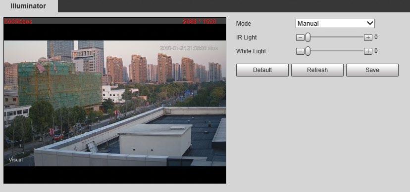
Step 3 Click Save
6.4.2 Configuring Wiper
Step 1 Select Setting > Peripheral > Wiper.
Step 2
Configure the running mode.
● Timing: You can configure the Interval Time and Period
1. Interval Time: Interval from the point when the wiper starts to the point when the wiper stops.
2. Period: The working time of the wiper.
3. Click Save.
● Manual: Turn on and off the wiper manually.
1. Interval Time: Interval from the point when the wiper starts to the point when the wiper stops.
2. Click Start to get the wiper work in the interval time that you have just configured, and click Stop to stop it; click Once to get the wiper work for one round.
● Auto: Adjust the sensitivity according to the actual situation.
Step 3 Click Save
6.4.3 Configuring Fan
Step 1 Select Setting > Peripheral > Fan
Figure 6-53 Fan
Step 2 Select the Enable checkbox.
Step 3 Configure the running mode.
● Auto: Click Save, and the fan works automatically.
● Manual: Select the Enable checkbox to manually start the fan.
Step 4 Click Save.
6.4.4 Configuring Heater
Step 1 Select Setting > Peripheral > Heater
Figure 6-54 Heater
Step 2 Select the heat type as needed.
Step 3 Configure the heater parameter.
● Auto: Select Start Tem and Stop Tem as the temperature range for heater to start, and click Save. When the sensor temperature is in the range, heater works automatically.
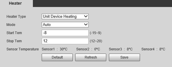
● Manual: When you think it is cold enough and you want to let the Camera work in a warm condition, you can select Manual as the Mode. Select the On checkbox, and then click Save
Step 4 Click Save


