


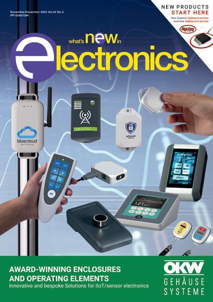
November/December 2022 Vol.42 No.3 PP100007394


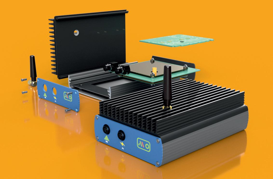
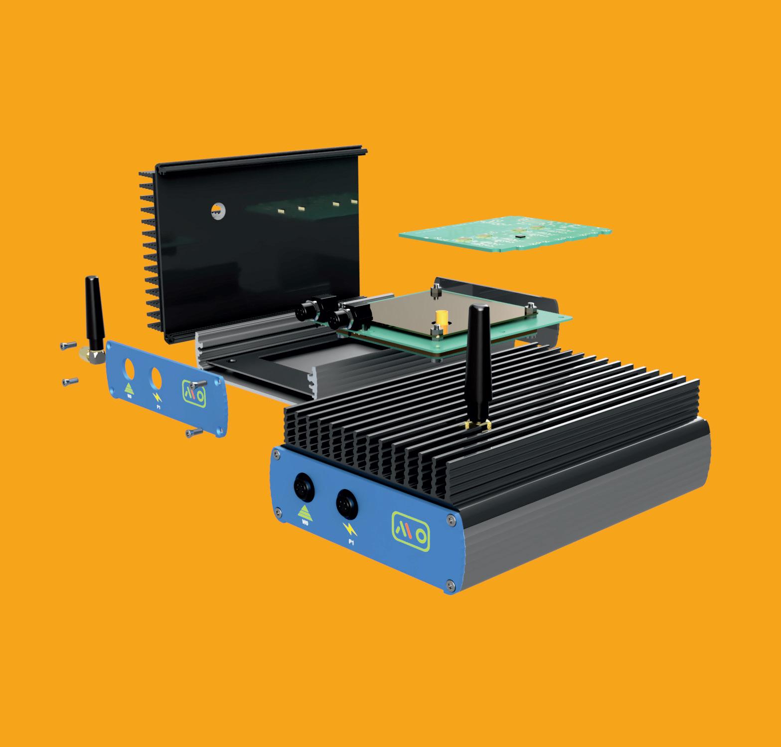
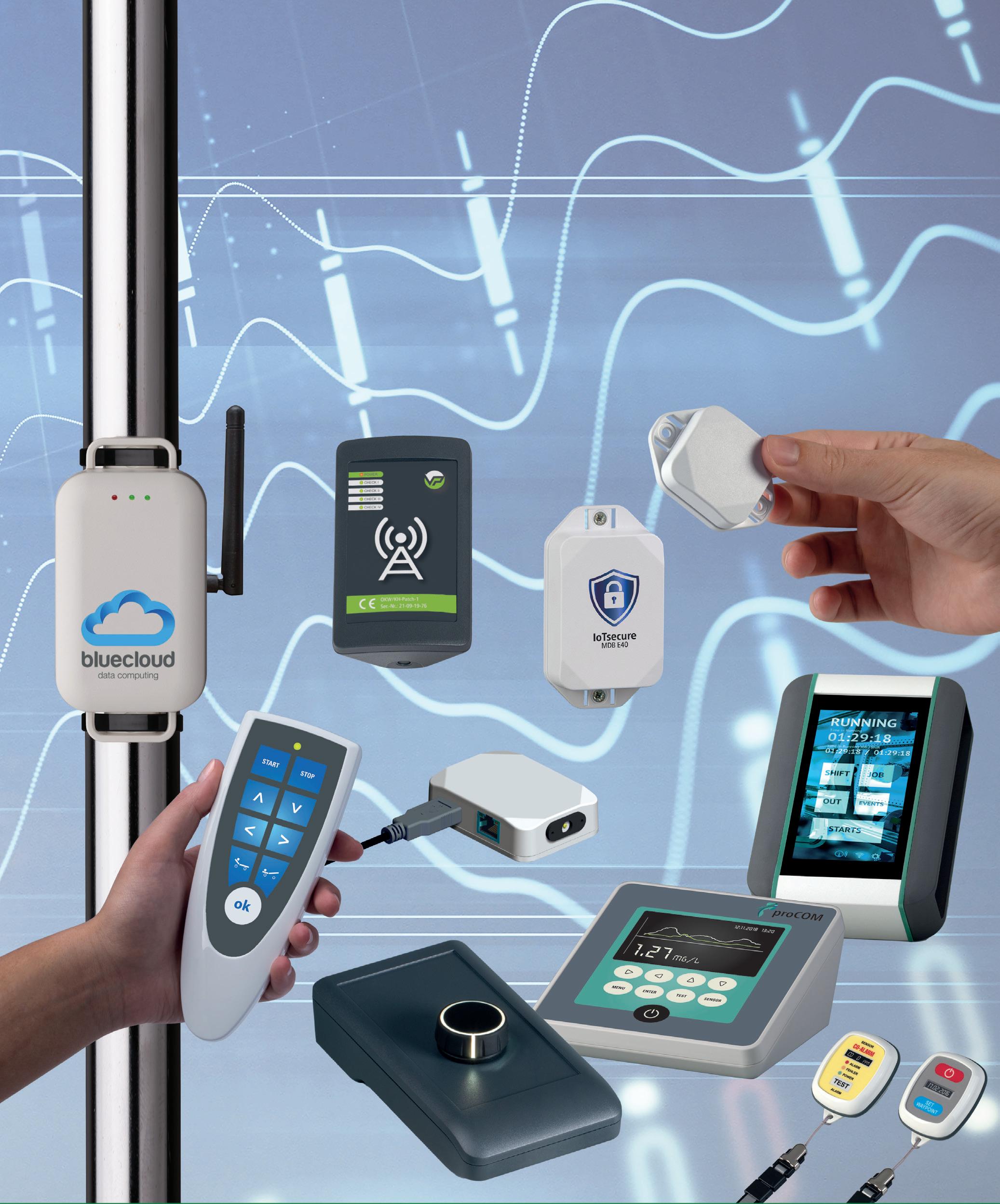
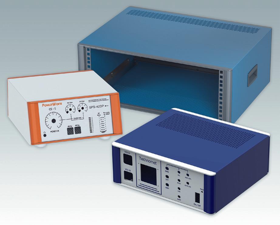
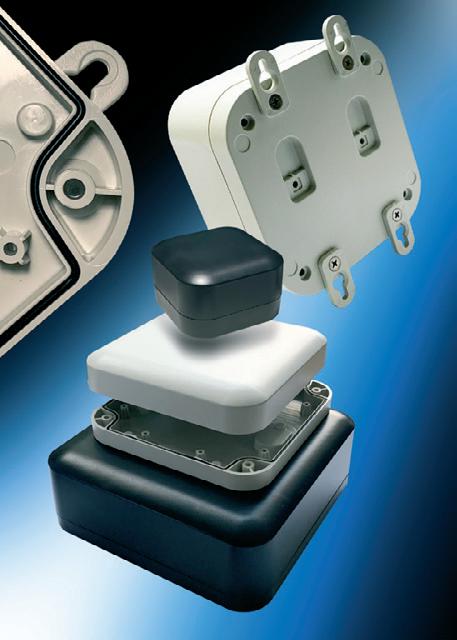
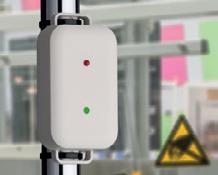
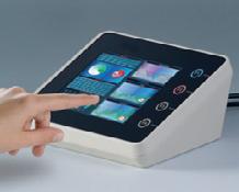
Award-winning plastic and aluminium enclo sures and operating elements are a suitable solution for IoT/IIoT sensor housings. The extensive range includes handheld, wear able, desktop, wall-mount and flush-mount enclosures, portable instrument cases, DIN rail enclosures, potting boxes and accessories. Potentiometer and tuning knobs include the latest models for menu-driven electronics.

Enclosures and tuning knobs provide solutions for a wide variety of different ap plications, including medical, laboratory and wellness equipment, test and measurement, control, automation, mechanical engineer ing, plant building, automotive engineering, climate control, construction equipment, security and building management systems, military/aerospace, communications and network technology.
The enclosures’ technical features include solutions for power supply and for installation of standardised displays; high protection classes; high-quality and easy-to-clean materials; recessed tops for membrane keypads and displays; and recesses for interfaces and connectors.
OKW’s wide range of enclosures ac cessories enables electronics designers to specify extra functionality. Accessories include docking stations, battery compart ments and contacts, belt clips, wrist straps, lanyards, bedrail clamps, wall-mounting kits, tilt and anti-slide feet, cable glands, grom mets and strain relief kits, IP sealing kits and Torx screws to help prevent tampering.
Customising options include CNC machining, lacquering, printing or laser marking of legends and logos, decor foils, special materials, EMC shielding, installation and assembly.
OKW Australia New Zealand P/L www.okw.com.au
ROLEC
WWW.ELECTRONICSONLINE.NET.AU CONTENTS COVER STORY WHAT'S NEW IN ELECTRONICS NOVEMBER/DECEMBER 2022 Your copy of What's New in Electronics is available as an online eMag. READ ONLINE! www.electronicsonline.net.au/magazine 4 The History of USB Standards from 1.0 to USB4 14 Do I specify IDC ribbon cables or discrete cables? 20 Enhancing communication efficiency for drones and IoT 25 Miniature cold-atom inertial sensors help navigation without GPS 29 What’s the difference between traditional resins and bio-based resins? 33 Nanocomposite films used to keep thin electronics cool 34 Australian solar pioneer receives European innovation prize
THE HISTORY OF USB STANDARDS FROM 1.0 TO USB4
 Smoot, CUI Devices
4 NOVEMBER/DECEMBER 2022 WWW.ELECTRONICSONLINE.NET.AU
Jeff
iStock.com/matejmo
The term USB is short for Universal Serial Bus. A “bus” is a circuit connection used to transfer data or power between components in an electronic system. A “serial” bus transmits data one bit at a time over a single wire.
USB is an engineering standard that establishes specifications for the connectors and cable used to link the various devices in an electronic system.

In a very simple sense, the USB standard allows for easy and convenient interconnect and data communication between devices. But it has evolved to do a great deal more. The development of the USB protocol and products associated with it was driven by the problem of interconnect complexity and slow data transfer inherent in computer systems of the early 1990s. The debut of the USB standard in 1996 simplified and streamlined the patchwork interconnect process. Since then, USB has been, quite literally, a story of speed bumps.
The refinement of the USB protocol and the products based on it spans a 25-year period and continues to evolve. The goal of the USB Implementers Forum (USB-IF), a consortium of more than 700 companies guiding the standard, has consistently been increased data communication speed, along with power delivery. The outcome has been broader adoption of computer technology across the business and computer markets based on easier device set-up and replacement.
Here are some of the specific develop ments in the USB standard and accompany ing hardware over the years since its initial release. To avoid confusion, we will initially refer to the original naming convention prior to changes made by the USB-IF in 2013. We will address those changes and confusion surrounding them throughout this article.
The interconnect landscape pre-1996
Prior to the development of USB, computer manufacturers used both serial and parallel ports, proprietary plugs, connectors, and cables to accomplish data transfer, often necessitating dedicated drivers and cards. Data transfer rates were slow, from 100 kilobytes (kB) per second for parallel to 450 kilobits (kb) per second for serial, and connection of devices often required the host computer to be disconnected or restarted.
Initial development of the USB standard began by the USB-IF in 1994. Several ver sions of the standard (USB 0.8 and USB 0.9) were announced that year as “pre-releases” that were not available commercially. An additional pre-release (USB 0.99) was an nounced in 1995 but was again not com mercially available.
USB 1.0
Early in 1996, USB 1.0 was issued as the first major release in the USB line. It of fered data transfer rates of 1.5 megabits per second (Mbps) at low speed and 12 Mbps at full speed. It was also self-configuring, eliminating user changes to device settings to accommodate peripherals. The interface was also hot-swappable, so devices could be changed without re-booting the host computer. Even though it was the first commercial version of USB, it was not widely accepted by the market and few devices were available to consumers.
WWW.ELECTRONICSONLINE.NET.AU NOVEMBER/DECEMBER 2022 5 CONNECTIVITY
its introduction, USB 3.0 has been updated with 3.2 naming conventions, and is now technically referred to as USB 3.2 Gen 1.
The USB 3.0 standard also increased the power transfer capability to 5 V and 900 mA. It supports physical connectors USB 3.0 Type A & B and USB Type C. To differentiate the connectors used with 3.0, elements in the devices are coloured blue.
USB 3.1 (or USB 3.2 Gen 2x1)
USB 1.1
A revised version of the initial standard was released in 1998. Labelled USB 1.1, it matched the data transfer rates of version 1.0, but could also operate at slower speeds for lower bandwidth devices. It was branded as Full Speed. Apple’s iMac G3 adopted the new USB standard and discontinued the use of serial and parallel ports in its machines. This move helped pave the way for wider adoption of the USB protocol by the industry and wide consumer adoption of USB products. Ver sion 1.0 and 1.1 specified the use of standard Type A (rectangular) or Type B (square with bevelled top corners) connectors.
USB 2.0
As the acceptance of PCs and their various peripherals increased in the market, and as the applications got more complex, the need for increased data transfer speed was apparent. USB 2.0 was released in April of 2000 with a data transfer rate of 480 Mbps. However, bus limitations reduced this to 280 Mbps. It was branded for marketing purposes as High Speed. The new version could also operate at 12 and 1.5 Mbps for devices requiring less bandwidth. It also of fered plug and play capability for multimedia and storage devices as well as support for power sources using USB connectors up to 5 V and 500 mA.
Additionally, it offered the ability for two devices to interact without the need for a separate USB host, also known as USB On-the-Go . USB 2.0 is compatible with USB Type A, B, and C connectors, as well as USB Mini and Micro A & B connectors. The release of Micro A & B connectors, however, did not happen until 2007.
In 2000, the first USB flash drives were also released commercially with up to 8 megabytes of storage capacity, furthering the acceptance of the USB standard. In today’s world, flash drives are available with storage in the terabyte range.
Wireless USB
The wireless USB standard (W-USB) was announced in May of 2005 for wireless short range network communication with a 10-metre range limit and a speed of 480 Mbps. This standard is no longer in use.
USB Micro
USB Micro connectors made their debut in 2007. Essentially smaller versions of the USB Mini-B connectors, they offered quicker charging speeds and data transfer than the mini devices. USB Micro connectors were largely introduced for use in standardising connections in Android mobile devices. Also, it should be clearly stated that the USB Micro connectors are a physical standard, not directly related to the communications standards such as USB 1.0, 1.1, and 2.0.
USB 3.0 (now USB 3.2 Gen 1)
The third major release of the USB stand ard acknowledged continuing demand for increased digital storage and bandwidth in the market. The USB 3.0 standard was re leased in November of 2008. It allowed data transfer rates up to a maximum of 5 gigabits per second (Gbps), but typically functioned at around 3 Gbps. This capability led to the standard being branded as SuperSpeedUSB USB 3.0 doubled the four connection lines of USB 2.0 hardware to eight and allowed for bi-directional transfer of data. It remains backwards compatible with USB 2.0. Since
Clarifying USB 3.2 naming conventions
Maximum Alternate Previous Name speed name name
USB 3.2 Gen 2x2 20 Gbps
USB 3.2 Gen 2 10 Gbps
SuperSpeed USB 20 Gbps USB 3.2
SuperSpeed USB 10 Gbps USB 3.1 Gen 2
USB 3.2 Gen 1 5 Gbps SuperSpeed USB 5 Gbps USB 3.1 Gen 1 or USB 3.0
The USB 3.1 version was an interim standard that is identical to 3.0, except that it increased data transfer rates up to 10 Gbps (USB 3.1 Gen 2). As with USB 3.0, the name for USB 3.1 was updated and is now called USB 3.2 Gen 2. With the upgraded transfer speeds, this earned it the designation SuperSpeed+. Released in July of 2013, version 3.1 used the same connectors (USB A, B, Mini & Micro) as 3.0.
In 2014, USB Type C connectors were also announced. First proposed in 2012, the Type C connector provides data, display, and power signals through a single, small connector that is also reversible. At about one third the size of the original USB Type A connector, the Type C is oval-shaped and somewhat thicker than the USB Mini and Micro versions. It incorporated additional wires and pins that added to its data potential.

USB 3.2 and USB Type C
USB 3.2 replaced the USB 3.0/USB 3.1 stand ards and made certain retroactive changes to those standards. With a continuing need for increased speed being the driving fac tor, USB version 3.2, another interim step, was introduced in September of 2017 and effectively doubled the data transfer speed to 20 Gbps (USB 3.2 Gen 2x2) by increasing the data transfer channels from a single lane to two. This was accomplished by adding USB Type C connectors. The increase to 20 Gbps is only possible using USB Type C cables which can transmit 10 Gbps in each direction over two wire pairs.
USB 4.0
USB 4.0, which was released in August of 2019, is based on the Thunderbolt 3 protocol. It features up to 40 Gbps of data transfer and, with the more recent Power Delivery 3.1 standard, power transfer of up to 240 W. Thunderbolt 3 was a protocol developed by Intel in 2015 to support high speed data and video transfer.
The USB 4.0 version does not need new connectors and uses the existing Type C con nectors. This allows data and video signals to effectively share lanes and achieve the
6 NOVEMBER/DECEMBER 2022 WWW.ELECTRONICSONLINE.NET.AU
CONNECTIVITY
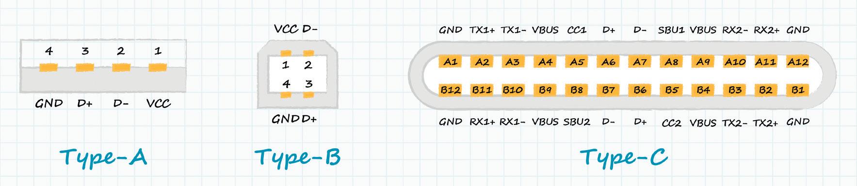
Physical Type A and Type B USB connectors.
>
Image credit: CUI Devices.

STM32H7 STM32H723/733, STM32H725/735, and STM32H730 • Cortex-M7 core running at the record-breaking frequency of 550 MHz • Up to 1MB internal flash • External memory interface: FMC and Octal SPI memory interface • FMAC (filtering) and Cordic (trigonometric) for mathematical acceleration • Advanced analog peripherals including two 16-bit ADCs and one 12-bit ADC • Interfaces to popular industrial connectivity standards, including three FD-CAN ports, Ethernet, and Parallel Synchronous Slave Interface • Chrom-ART Accelerator™ for superior graphics performance • Scalable architecture with state-of-the-art cyber protection • Graphic, AI, Security solutions and STM32Cube ecosystem supported STMicroelectronics Suite 703, 247 Coward Street, Mascot, 2020, NSW Australia Tel: +61 2 9158 7201 Email: clifford.shi@st.com Authorized Distributors ARROW Electronics Australia Pty Ltd - Tel +61 2 9737 4900 Future Electronics - Tel: +61 2 8064 0000 Avnet Electronics (Australia) Ltd - Tel: 1300 791 695 st.com/stm32h7
maximum bandwidth usage of the device, optimising data transfer speeds. It is also backwards compatible (using adapters) with USB versions 2.0 and 3.2, although speeds will suffer.
This newest version of the USB standard also offers Intelligent Power Delivery, al lowing a USB 4.0 cable to deliver as much power as a connected device requires, up to 240 Watts and 5 Amps. Power delivery is also bi-directional, meaning it can flow to or from the connected device.
A word about connectors
As has been mentioned, the different ver sions of the USB standard have spawned a variety of connectors — 14 so far, to be exact. Even though the physical form fac tor and the USB protocol are technically independent, there is an interrelationship in regards to which protocols work with particular form factors. With that in mind, here is a quick review of some of the most prominent types used.
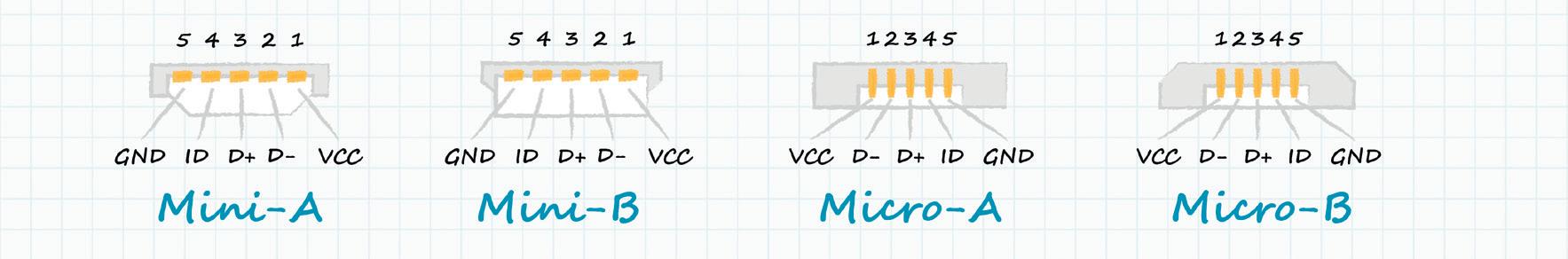
• USB Type A: the first, and most widelyknown USB connector has been in use since the standard was first released. It has a flat, rectangular shape and is only insertable in one orientation.
• USB Type B: smaller than Type A and is square in shape with slightly bevelled corners on the top and a large space on the inside.
• USB Mini-B: compact sized, 5-pin con nector used in older cell phones and digital cameras, largely replaced by the Micro-B.
• USB Micro-B: smaller and flatter than the Mini-B, used in many smart phones.
• USB 3.0 Type A: flat and rectangular similar to Type A, but with square pins and blue internals for identification. Also known as SuperSpeed.
• USB 3.0 Type B: designed for Super Speed applications, with two stacked rectangular sections and blue internals for identification.
• USB 3.0 Micro-B: small, flat and rectan gular with two distinct sections. Designed to carry data and power for SuperSpeed applications.
• USB Type C: reversible symmetrical de sign with rectangular shape and rounded corners. Newest USB connector device.
Decoding USB naming conventions
In an attempt to clear up market confusion, beginning with the USB 3.2 standard, the USB-IF has implemented a series of nam ing changes. The original USB 3.0 and USB 3.1 terms were dropped and replaced by a three-tiered scheme.
The first tier was known as USB 3.2 Gen 1 (previously USB 3.0 and USB 3.1 Gen 1). It was initially branded as SuperSpeed USB , with data transfer rates up to 5 Gbps. The Gen label refers to generation and the number following it refers to the number of data lines. The most recent branding for this has been changed to SuperSpeed USB 5 Gbps
The second tier is labelled USB 3.2 Gen 2 (formerly USB 3.1 Gen 2). It was initially branded as SuperSpeed 10 Gbps with data transfer up to 10 Gbps. This marketing term remains the same.
The third tier is USB 3.2 Gen 2x2 (formerly USB 3.2). This level was initially branded as SuperSpeed USB 20 Gbps and this term remains in place. It has data transfer speeds up to 20 Gbps.
The USB-IF has also refined the USB 4.0 naming, changing it to USB4 with the following two tiers:
• USB4 20 Gbps (data speed matches its naming)
• USB4 40 Gbps (data speed matches its naming)
Each of these tiers has a new logo associ ated with it for use on products. It is hoped that this will help to clear up any consumer confusion in the marketplace. The variety of names for the USB standards continues to cause some concern and confusion in the market, however, as devices are still often referred to under the old naming scheme.
The continuing relevancy of USB
The USB standard served to clear up the hornet’s nest of connectors and cables that were originally used to link peripheral devices to host computers. The ongoing evolution of this standard, and the devices that support it, has meant increased data speeds and power delivery via a small, inexpensive, and easy-to-use interface.
What began as a way to connect pe ripherals, became a way to improve the user experience with all types of products, including smart phones and other mobile devices, games, toys, smart home products, and industrial networking. USB devices are also frequently used today simply for charging purposes.
These features have helped to make USB the dominant signal transfer technol ogy in use around the world today, while the applications for USB technology will only continue to grow. CUI Devices offers a range of USB connectors and USB cables in various form factors designed to meet multiple USB standards.
This article has been reprinted with permission from CUI Devices. It was originally published on the CUI Devices website.
CUI Devices www.cuidevices.com
8 NOVEMBER/DECEMBER 2022 WWW.ELECTRONICSONLINE.NET.AU
USB physical connector form factors. CONNECTIVITY
Image credit: CUI Devices.

SHORTcircuits
COMMUNICATION SIGNAL DEVELOPED FROM ENVIRONMENTALLY FRIENDLY BATTERY
The NTT Corporation and the Graduate School of Frontier Sciences, the University of Tokyo (GSFS) have produced what is reportedly the world’s first communication signal using a battery and a circuit composed of environmentally friendly materials, free of scarce elements and hazardous substances. As the Internet of Things (IoT) proliferates, all sorts of objects are being transformed into devices, expanding their range of services and applications. However, concerns exist about the environmental impact of the disposal of consumables converted into sensor devices.
To address this issue, the NTT is promoting the research and development of devices using materials that have a lot environmental impact once discarded.
NTT and GSFS are exploring improvements to environmentally friendly batteries by eliminating the use of scarce materials and hazardous substances; the two organisations have manufactured a proof of concept (PoC) sensor device made from an environmentally friendly circuit using organic semiconductor technology and have succeeded in generating what is reportedly the world’s first communication signal using these types of sustainable materials. This technology could be used for sensing devices in unsealing detection (for example, in single-use water bottles), sensing devices in pill packages to determine if a patient has
STRENGTH IN NUMBERS WHEN IT COMES TO INERTIAL SENSORS
Researchers working in the field of navigation and supported by the Swiss National Science Foundation (SNSF) have developed a method that allows several low-cost inertial sensors working in combination to replace a single expensive sensor.
Inertial sensors such as accelerometers and gyroscopes are used nearly everywhere, from smart watches to submarines, drones, spacecraft, vacuum cleaners and even game controllers. The purpose of these sensors is to indicate the position, speed or direction of an object. Their drawback is their lack of precision, at least when it comes to the low-cost versions used in many devices.
Now there may be a way to solve this problem, with researchers from the University of Geneva reporting that networking several inexpensive sensors is a viable alternative to more powerful sensors. By combining the measurements of several low-cost, individual sensors, the researchers succeeded in obtaining a very precise navigational measurement. Their breakthrough was published in the journal IEEE Transactions on Signal Processing
“It is as if we had created a virtual sensor, and it is particularly efficient because it uses all the information provided by the individual sensors,” said Yuming Zhang, a PhD candidate in statistics and lead author of the new study. These virtual sensors not only offer the same performance as actual sensors but are also less expensive
forgotten to take their prescribed medication or reducing the environmental impact of observational weather buoys.
In 2018, the NTT manufactured and verified the battery operation of the Return-to-the-Earth-Battery (composed of fertiliser ingredients and organic materials). Then, the collaborators interviewed experts in the field of waste management to determine what materials should be selected to achieve low environmental impact. In response the pair eliminated materials containing scarce elements and hazardous substances. Using these materials, researchers at NTT collaborated with Professor Junichi Takeya’s laboratory at GSFS to create an environmentally friendly circuit.
This was achieved by developing an organic transistor manufacturing process in which all electrodes are made of carbon material (carbonelectrode organic transistors) and are used to construct analog oscillation circuits and digital modulation circuits with CMOS. Researchers formed a three-dimensional conductive porous structure, applied carbon as an electrode and increased the voltage by serialising the batteries.
The NTT will continue developing related technologies, collaborating with external organisations and companies to explore use cases unique to ‘low environmental impact’ and jointly implementing novel services. More details about this research are available in Scientific Reports

and can be more flexibly configured. They could therefore be used in a number of consumer devices without increasing their cost.
The idea of combining information from different sensors is not new, but until now technical constraints have limited its application. As explained by Zhang, “Sensor measurement errors are very complex to handle individually, and even more so when several sensors are combined.” The team solved the problem using a new signal decomposition approach, which makes it possible to understand and deal with errors that affect measurements and to process them using a novel statistical method.
According to the researchers, the potential applications of the new technique widely range from aerial mapping using drones to autonomous vehicles. In addition, the ability to optimally combine different sensor technologies could help develop a new generation of global positioning systems.
10 NOVEMBER/DECEMBER 2022 WWW.ELECTRONICSONLINE.NET.AU
iStock.com/Petmal
iStock.com/seregalsv

SHORTcircuits
AUSTRALIAN QUANTUM INDUSTRY POISED TO REACH $6 BILLION BY 2045
Quantum technology is forecast to reach $6 billion and generate more than 19,000 jobs in Australia by 2045, according to updated market projections released by CSIRO, Australia’s national science agency. CSIRO’s original Growing Australia’s Quantum Technology Industry Roadmap has been updated two years on and reflects the growth trajectory of quantum technology across the report’s three key domains of quantum computing, sensing and measurement, and communications. The report provides estimates and refinements of the original modelling and extends the forecast from 2040 to 2045 while affirming the economy results from the earlier report.
CSIRO Senior Economist Mingji Liu said that the updated figures reflected recent domestic and global developments in quantum technology opportunities. “Our updated modelling reaffirms that quantum technology continues to be a significant opportunity for Australia in the years to come. Although there is still uncertainty as to how quantum technology will be commercialised both around the world and domestically, the startup funding and investment in quantum is encouraging,” Liu said.

The economic modelling forecasts that by 2030, Australia’s quantum technology opportunity in revenue terms could conservatively reach $2.2 billion and could generate 8700 jobs. In five years, this could reach $3.3 billion by 2035, and then reach $4.6 billion by 2040 and could generate 16,100 jobs (the same as original projections in 2020). According to CSIRO Quantum Technologies Director Jim Rabeau, the last 18 months have seen a significant increase in focus to strengthen Australia’s position in the emerging global quantum industry. “CSIRO has launched its Future Science Platform, a number of new companies have been backed or reached key milestones, a tech industry group has been formed and we’re seeing an intensive national focus. The key now will be to sustain and grow over the long term,” Rabeau said.
CSIRO Chief Executive Larry Marshall said that Australia is at a pivotal stage of growing its quantum industry and is at a tipping point between research and commercial development. “We need to harness our bold vision for what this breakthrough technology could mean for some of our largest industries,” Marshall said.
PHYSICISTS DESIGN NEW TYPE OF UNIVERSAL QUANTUM COMPUTER
The computing power of quantum machines is low and increasing it can be challenging. Physicists from the University of Innsbruck have presented a new architecture for a universal quantum computer that overcomes such limitations and could be the basis of the next generation of quantum computers.
Quantum bits (qubits) in a quantum computer serve as a computing unit and memory at the same time. Because quantum information cannot be copied, it cannot be stored in a memory as in a classical computer. Due to this limitation, all qubits in a quantum computer must be able to interact with each other; this still presents a challenge for building powerful quantum computers. In 2015, theoretical physicist Wolfgang Lechner, together with Philipp Hauke and Peter Zoller, proposed a new architecture for a quantum computer, now named LHZ architecture after the authors. According to Lechner, the architecture was originally designed for optimisation problems, but in the process, the physicists reduced the architecture to a minimum in order to solve these optimisation problems as efficiently as possible. The physical qubits in this architecture do not represent the individual bits but encode the relative coordination between the bits. “This means that not all qubits have to interact with each other anymore,” Lechner said.
Lechner has now shown that this parity concept is also suitable for a universal quantum computer. Parity computers can perform operations between two or more qubits on a single qubit. “Existing quantum computers already implement such operations very well on a small scale. However, as the number of qubits increases, it becomes more and more complex to implement these gate operations,” said Michael Fellner, one of the scientists on Lechner’s team.
In two publications in Physical Review Letters and Physical Review A , the Innsbruck scientists have shown that parity computers can, for example, perform quantum Fourier transformations — a fundamental building block of many quantum algorithms — with fewer computation steps and thus more quickly. “The high parallelism of our architecture means that, for example, the well-known Shor algorithm for factoring numbers can be executed very efficiently,” Fellner said.
The new concept also offers hardware-efficient error correction; because quantum systems are very sensitive to disturbances, quantum computers must correct errors continuously. Significant resources must be devoted to protecting quantum information, which increases the number of qubits required.
12 NOVEMBER/DECEMBER 2022 WWW.ELECTRONICSONLINE.NET.AU
Image credit: CSIRO
iStock.com/Bartlomiej
Australia has strong research capabilities in quantum hardware development and quantum information science, both of which are critical to the development of the hardware and software stack needed to enable functional quantum computing applications.
Wroblewski
CEA’S RF CHIP ENABLES IoT CONNECTIVITY FOR REMOTE DEVICES


CEA, a French technology-research organisation, and Astrocast, a global satellite Internet of Things network operator, have announced their successful collaboration on a low-cost, bidirectional communication module that enables corporations to communicate with their remote assets in areas not covered by terrestrial networks.

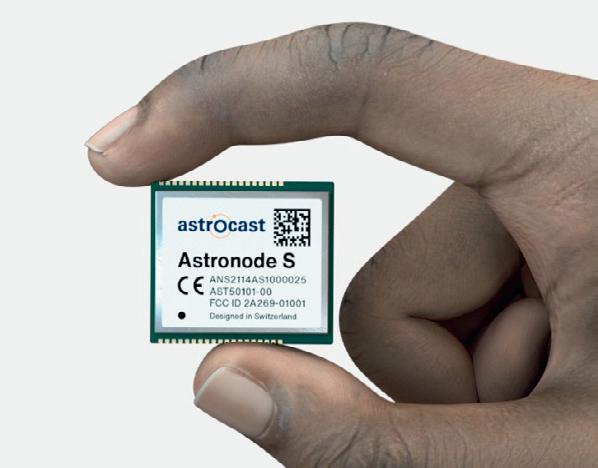
The module’s L-band chip, based on a new architecture developed by CEA’s Laboratory of Electronics Information Technology (CEA-Leti), is a key hardware component that enables Astrocast customers to benefit from cost-efficient communication with their assets in the field through its network. Completed earlier this year in an expedited project between the research institute and Astrocast, it is embedded in Astrocast’s RF module, Astronode S.
The chip’s architecture is split over the RF core and digital processing and control units. It is fully optimised to support Astrocast’s dedicated bidirectional ground-to-satellite protocol and provides an optimal trade-off between link budget and low-power and low-cost constraints. The chip also embeds all low-Earth orbit (LEO), satellite-specific features such as satellite detection and robustness to Doppler shift.
The miniaturised, surface-mount module communicates with terrestrial devices via Astrocast’s constellation of LEO satellites.
Using the L-band spectrum, the network primarily targets maritime, oil and gas, agriculture, land transport and environmental applications in which ubiquitous coverage is required.
“Terrestrial IoT networks cover only about 15%, which leaves vast remote and rural areas where our global satellite network provides coverage that is crucial for our target markets,” said Laurent Vieira de Mello, COO, Astrocast. “Leveraging its expertise embedded in a preliminary version of the RF chip, CEA-Leti developed its chip and delivered the final prototype to meet our requirements and timeto-market goals. They managed the chip technology transfer to our industrialisation, qualification and production partner.”
The project was managed through a flexible collaboration model covering both prototype and industrialisation phases. Michael Durr, Business Development Manager at CEA-Leti, said: “An accelerated time-to-market goal drove this project … We pioneered this RF technology in 2019, and our team customised it for Astrocast up to production in only three years.”
WWW.ELECTRONICSONLINE.NET.AU NOVEMBER/DECEMBER 2022 13
Image credit: Astrocast
DO I SPECIFY IDC RIBBON CABLES OR DISCRETE CABLES?
Wendy Preston, Senior Technical Sales Engineer, Harwin
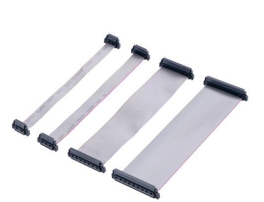
Despite the rise of wireless, cables are still vitally important in modern electronics, and necessary within equipment enclosures.
Both ribbon cabling and individual (discrete) wires are common, and both IDC and single crimp con nections give reliable connectivity. So how do you choose?
What is an IDC connection?
IDC is an initialism for Insulation Displace ment Contact or Connector. That name also describes the way the contact makes connection to the cable conductor.
The rear of the connector, where the cable connection is located, has two rows of twin fork shapes. Each of these shapes has sharp points and a U channel between. The two rows of forks are offset by half a pitch — for instance, a 1.27 mm pitch con nector has the rows offset by 0.635 mm, ready for a 0.635 mm pitch ribbon cable.
When you push the ribbon cable onto the rows of contacts, the sharp points pierce through the insulating rubber material, push ing it out of the way (displacing it). As you push the cable further down, the sides of the centre conductor are now in contact with the inside faces of the U channel. The conductor is squeezed slightly, ensuring a good connec tion joint between the cable and the contact.
This is where the name comes from — the insulation is displaced by the contact beams.
What is a discrete cable?
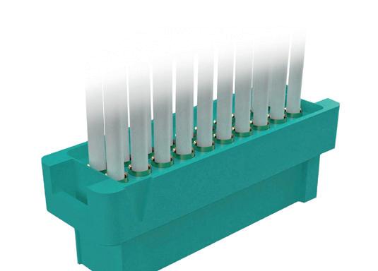
To make sure we’re comparing like-for-like, we’ll quickly define discrete cabling. This is a connection method that involves single cables with a single conductor (stranded or solid). These are often called equipment wires. You would attach them to single contacts, one at a time — whether that’s by crimping or soldering. Solder cup contacts may be pre-assembled into the connector, but crimp contacts will also need assembling to the housing.
The BIG advantage of IDC
It’s a really big advantage in terms of as sembly processes — with IDC and ribbon cables, you’ll connect all your conductors in one action.
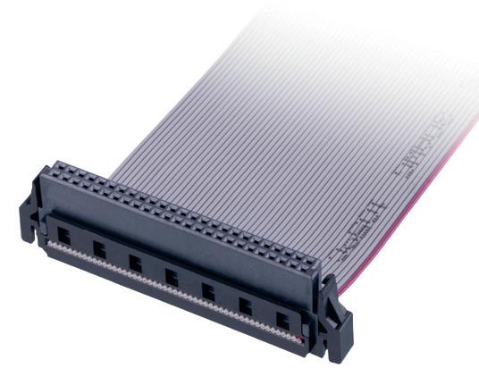

An IDC connector has a bar that goes over the back of the connections. This bar helps push the ribbon down into the right position. It also makes sure that in use, the cable stays on the contacts, and that the sharp beam ends are covered up.
If you’ve only got a few contacts in your connector, it might be possible to do this assembly just by hand. But the more contacts you have the more force you’ll need, so tooling is available to help. This tool works like a vice or clamp and helps push the contact, cable and bar together.
Clearly, this process is much quicker than discrete single cables, where every single contact must be (a) stripped, (b) crimped or soldered, (c) inspected and (d) assembled into the housing (depending on contact type).
This is a big saving in time, which means saving in costs. So why are aren’t all cable assemblies using IDC and ribbon cables?
Why discrete cables win over IDC:
• Cable sizing: To make sure the ribbon cable conductor makes a good connection with the IDC contact, it’s important that the forks and U channel are exactly the right size. The IDC end of the contact must be designed for a specific cable size and type — including the difference between solid and stranded core. And all those connections must be the exact same wire size — no mixing cable sizes in one connector. With discrete contacts and cables, mixing is possible.
14 NOVEMBER/DECEMBER 2022 WWW.ELECTRONICSONLINE.NET.AU
Image credit: Harwin
DISCRETE CABLING IS A CONNECTION METHOD THAT INVOLVES SINGLE CABLES WITH A SINGLE CONDUCTOR (STRANDED OR SOLID).
• Cable duplication: If you have multiple connectors in your designs for, say, 10, 20 and 40 contacts, then you also need to keep stock of 10, 20 and 40 conductor ribbon cables. With discrete cabling, you just use the same reel of cable for every connection. IDC requires more storage space for cabling, and less chance of discounts due to economies of scale.

• Cable routing: Ribbon construction can limit the amount of routing you can do with the cables. Bundles of individual cables are often more flexible, and each wire moves independently to get your harness through and around obstacles.
• Connector availability: Because IDC con tacts are more difficult to design and the sizing issue limits their flexibility, there are just fewer connector choices out there. And ribbon cable sizes normally stop at 22 AWG, so that’s no good if you have higher current requirements.
Finally, IDC contacts are not generally a good design choice for high reliability con nectors that need to withstand the extremes of vibration, shock and temperature.
The performance of the contact design for IDC contacts often doesn’t match the more rugged and capable contact design we use on connectors like Datamate and Gecko.
Making the decision
So how do you choose? Consider that your options will often be dictated by the con nector performance you need. Make sure you first know what specifications you need from the connector, as that may eliminate one or other connector type.
If you still have a cabling choice, con sider if it’s a one-off, whether you have cable routing restrictions, and whether there are ready-made cables available. If you’re making cable assemblies in-house, do you have the tooling or training for a particular type already? Harwin’s experts are ready to help guide you through the variety of cable connection styles and can eliminate the problems of in-house limitations with ready-made cable assemblies.
This article has been reprinted with permission from Harwin. It was originally published on the Harwin website.
Harwin
https://www.harwin.com/
WWW.ELECTRONICSONLINE.NET.AU NOVEMBER/DECEMBER 2022 15
iStock.com/Vera Aksionava
CABLING
LINEAR ACTUATOR
The L series Linear Actuator from FAULHABER of fers a turnkey solution for a range of applications. The innovative design of the L series provides high performance in compact dimensions and can support large input speed or high output force. Therefore, it is well suited for a range of applications like robotics, industrial machines and laboratory equipment.
The Series includes 22L (22 mm diameter) and 32L (32 mm diameter) options which use GPT gear technology. These can be combined with a range of DC motors, 4-pole and 2-pole brushless mo tors or stepper motors. A range of gear reduction ratios is also available, so it is simple to select a configuration to fit various force or speed operating points for the application in question.
Options such as different screws or various flange and nut configurations are also available to match different ambient conditions making mechanical integration in applications easier. Customer-specific modifications are also possible in order to enhance performance and fulfil specific needs, like accuracy.
Product options can refer to the coupler, to the screw or both. For example, screw type and length, and nut type and length. Other options include ambient conditions like particular temperature range or special environmental conditions as vacuum; and different motor cable or terminals orientation when integrating the combination unit inside the application.
ERNTEC Pty Ltd www.erntec.net
CUSTOM ALUMINIUM ELECTRONIC ENCLOSURES
Metal electronic enclosures manufacturer METCASE has extended its range of ‘no extra cost’ custom paint colours and finishes. METCASE has added eight new shades to its range of always-in-stock paints — bringing the total to 37 colours plus anodising, passivate, pre-treatment and anti-corrosion finishes.
The new paint colours are violet blue (RAL 5000), cobalt blue (RAL 5013), pigeon blue (RAL 5014), yellow (Pantone 1235C), medium dark orange (Pantone 159C), salmon orange (Pantone 2027C), teal (Pantone 2238C) and anthracite (Pantone 432C).
METCASE can supply its 19 ″ enclosures and desktop/portable instru ment enclosures in any specified RAL or Pantone colour. However, there is no extra charge if the customer chooses a colour from the alwaysin-stock range.
METCASE has a range of in-house facilities, including a powder paint line and a wet paint cubicle. Its team can supply enclosures and front panels in any custom colour or special finish. There is usually a minimum order of 10–25 units but this does not apply to always-in-stock colours.
Finishes include tough powder polyester painting, chip-resistant wet painting, nickel-loaded EMC shielding lacquers for plastic parts, blemishfree finishing, anodising, Iridite NCP (conductive/anti-corrosion), plus zinc and clear passivate of CR4 steel panels.
Other customisation services include bespoke sizes, custom front panels, CNC machining, fixings and inserts, and photo-quality digital printing of graphics, legends and logos.
ROLEC OKW Australia New Zealand P/L www.metcase.com.au
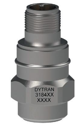
RUGGED INDUSTRIAL ACCELEROMETER
The Dytran model 3184F is a rugged IEPE piezoelectric accelerometer with a built-in Faraday shield for elec trostatic noise immunity, a sensitivity of 100 mV/g and a good low-frequency response.
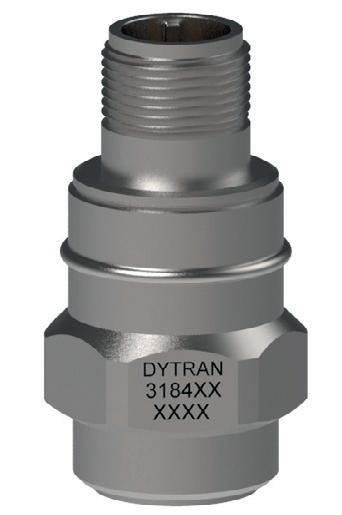
The model incorporates a ceramic shear sensing element, packaged in a stainless steel housing with a 2-pin MIL-C-5015 axial connector. It is also directly compatible with the series 6194 Immersion Proof sealing boot. When used together, the sensor remains fully functional in an IP65 environment. Case isolated to avoid EMI/ ground loop interference, the product is hermetically sealed for operation in high humidity and dirty environments.
The device has a 50g range and EMI/RFI protection. It weighs 135 g and operates at temperatures from -4.5 to +70°C. Applications include industrial vibration monitoring, turbo engine testing, walkabout data collection and general-purpose vibration monitoring.
Metromatics Pty Ltd www.metromatics.com.au
16 NOVEMBER/DECEMBER 2022 WWW.ELECTRONICSONLINE.NET.AU
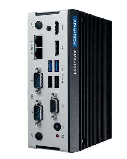
DIN-RAIL EDGE COMPUTERS

The ARK-1221L and ARK-1250L computers feature ultra-compact, rugged and fanless designs that support wide operating temperature ranges (-40 to 60°C; -40 to 140°F) and voltage input. Both com puters support 5G/LTE integration, enabling higher efficiency and increased productivity when used in factory and smart city applications. They also support Windows 10 and Ubuntu for easy deployment and integration. In addition, by adding TPM chips on request, they enable high-level hardware-based security. This series is designed with front-facing I/O that support integration in cabinets and spacelimited environments common in machine vision, equipment control and smart factory applications.
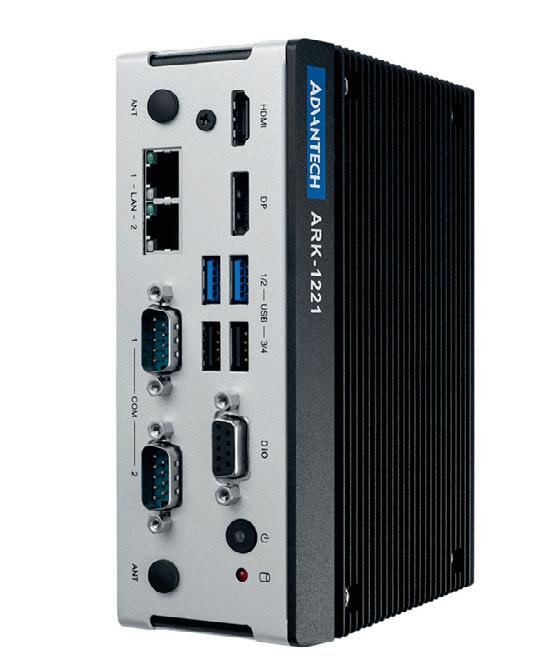
The ARK-1221L features the Intel Atom x6413E Quad Core CPU (Elkhart Lake) and supports up to 32 GB DDR4-2666 memory for computing-intensive IoT operations. ARK-1221L utilises WISE-DeviceOn to provide a 5G-ready IoT gateway for remotely managing edge devices, reducing downtime and maintenance costs, and increasing processing efficiency and productivity.
Powered by 11th Gen Intel Core i5/i3 processors (Tiger Lake), ARK-1250L delivers responsive, highperformance computing power with AI/deep learning capabilities and low power consumption. ARK-1250L supports versatile I/O connection and over 10 selected iDoor I/O expansion modules. These modules are designed to provide high flexibility for a range of AOI, AGV/AMR and industrial equipment control applications. Likewise, ARK-1250L features 4 x RS-232/422/485 for motor and radar sensors, 1 x optional CANbus for robotic arms, 3 x USB 3.2 for peripherals like vision cameras and 3 x GbE (2 x are up to 2500 Mbps) for connectivity. Advantech Australia Pty Ltd www.advantech.net.au
180 x 135 mm - australia
WWW.ELECTRONICSONLINE.NET.AU NOVEMBER/DECEMBER 2022 17
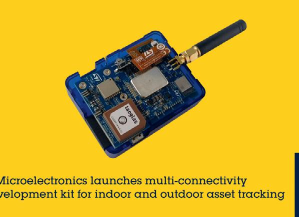
MULTI-CONNECTIVITY EVALUATION PLATFORM
The STMicroelectronics STEVAL-ASTRA1B multi-connectivity evaluation platform is designed to provide a complete ecosystem for building proof of concept for asset tracking systems. Battery-powered, and with a small form factor, the evaluation kit includes firmware to simplify development targeted applications such as livestock monitoring, fleet management and logistics.
The kit helps users evaluate short- and long-range STM32 wireless System-on-Chip (SoC) devices.
The STM32WL55JC sub-GHz SoC for long-range connectivity (LPWAN) implements the LoRaWAN protocol and provides LoRa, (G)FSK, (G)MSK and BPSK modulations. The other wireless SoC is the STM32WB5MMG module for 2.4 GHz Bluetooth Low Energy and Zigbee connectivity. Each device has an Arm Cortex-M4 core for application processing with a dedicated Cortex-M0+ to manage the radio.
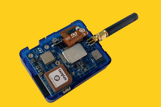
The development kit includes an ST25DV64K near-field communication (NFC) contactless chip for secure pairing and com munication and an STSAFE-A110 secure element for privacy and to guard against hacking. A Teseo-LIV3F miniature GNSS module also provides outdoor positioning. Numerous ST sensors are integrated for monitoring asset condition and environment. These include an STTS22H low-voltage, ultra-low-power temperature sensor with ±0.5°C accuracy, HTS221 digital humidity and temperature sensor, LPS22HH barometric pressure sensor and LIS2DTW12 ultra-low-power 3-axis accelerometer. There is also an LSM6DSO32X always-on inertial module, which contains a 3D accelerometer and 3D gyroscope with machine-learning core.
The evaluation platform has a smart power and battery-management architecture to help increase application runtime. It also includes the ST1PS02 nano-quiescent synchronous step-down converter, STBC03 Li-ion battery charging controller and TCPP01-M12 USB-C port-protection IC. The evaluation platform also includes a comprehensive ecosystem that includes software and tools to help users ‘road-test’ applications in development — these include the FP-ATR-ASTRA1 STM32Cube software function pack with firmware libraries and typical application examples. In addition, the DSH-ASSETRACKING web-based cloud dashboard simplifies the creation of an end-to-end proof of concept and is free of charge for demonstration purposes.
STMicroelectronics Pty Ltd www.st.com

TYPE C RECEPTACLES AND PLUGS
Würth Elektronik offers OSB 2.0 Type C receptacles and plugs for devel opers who want to use the USB-C connector format for their application, but don’t need the high data rates that come with the USB 3.1 standard. Under the name WR-COM USB 2.0 Type-C, Würth Elektronik presents a horizontal receptacle and vertical plug versions of the symmetrical connector based on the older USB standard.
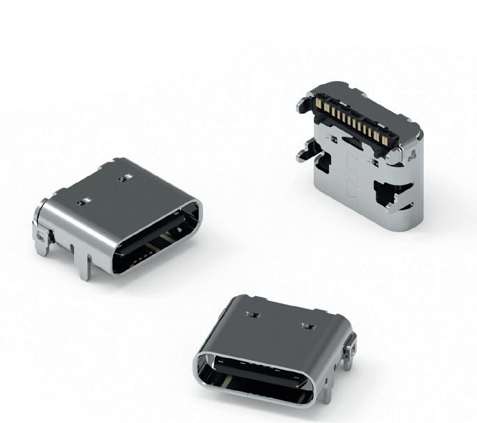
Those who use the USB 2.0 version of type-C plugs can nevertheless use the higher charging current of the 3.1 standard and transfer up to 100 watts of power.
WR-COM USB 2.0 Type C is designed for longevity. The SMT-mountable components come with additional solder pads for strong mechanical fixation on the PCB. The doubled contacts are gold-plated. The durabil ity of the connectors is approximately 10,000 mating cycles. They are designed for the industrial operating temperature range of –40 to +85°C.

The cost-effective solution for charging mobile devices via USB-C is now available from stock without a minimum order quantity. Free samples are available.
Wurth Electronics Australia Pty www.we-online.com
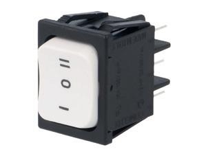
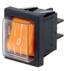
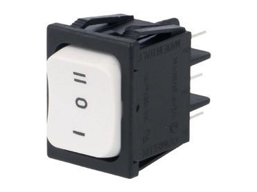
ROCKER SWITCHES
Illuminated rocker switches are used in many different areas — from industrial applications to consumer equipment (such as home appliances). Mounted on a panel, the switches are a safe way of turning high-voltage circuits on. COMELUX’s 40 series of durable rocker switches can handle currents up to 16 A and standard mains voltages, ie, 250 VAC. The switches are plugged into the circuit with the use of flat, slide-in, standard size connectors. They are bistable components of different illumination colours. Additionally, selected models have been equipped with elastic covers that upgrade their IP rating. This means the user never has to directly touch the switching mechanism, protecting operators from electric shock in the event of spilling liquid on the panel of a live device.
Transfer Multisort Elektronik www.tme.eu
18 NOVEMBER/DECEMBER 2022 WWW.ELECTRONICSONLINE.NET.AU
VORTEX TUBES
EXAIR Vortex Tubes provide a maintenance-free solution to a variety of industrial spot cooling problems. Using an ordinary supply of compressed air as a power source, vortex tubes create two streams of air, one hot and one cold, with no moving parts.
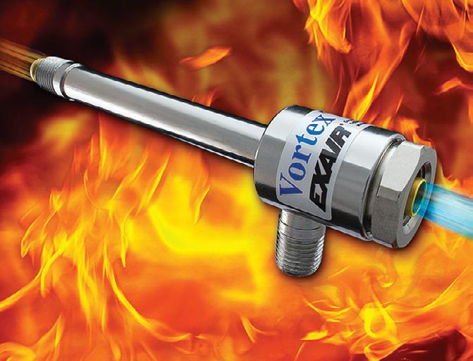
Vortex tubes can produce temperatures from -46 to +127°C, flow rates from 1 to 150 SCFM (28 to 4248 SLPM) and refrigeration up to 10,200 Btu/h (2571 Kcal/h). Temperatures, flows and cooling power are adjustable over a wide range using the control valve on the hot end exhaust.
Over the years, the basic vortex tube has been used in a multitude of industrial cooling applications, leading to the development of applied products de signed to suit the specific application. These include the Adjustable Spot Cooler, Mini Cooler, Cold Gun and Cabinet Coolers for cooling and purging electronic control panels.
Standard vortex tubes are suitable for ambient tem peratures up to 52°C. High-temperature vortex tubes for ambient temperatures above 93°C are also available.
Applications include cooling electronic controls, cooling machining operations, cooling CCTV cameras, setting hot melts, cooling soldered parts, cooling gas samples, electronic component cooling, cooling heat seals and cooling environmental chambers.
Compressed Air Australia Pty Ltd www.caasafety.com.au
INDUSTRIAL THERMAL SOLUTIONS
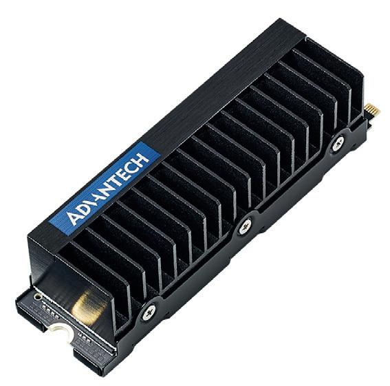
Advantech, a global embedded computing leader, has released a pair of SQFlash PCIe Gen.4 SSD solutions: the SQF 930 and SQF ER-1.
The Advantech SQF 930 and ER-1 series are designed with PCIe Gen. 4 specifications, delivering double data streaming performance when compared with Gen. 3 solutions. In addition, these solutions are also available in M.2 2280 and U.2 (SFF-8639) sizes to accom modate diverse requirements. In order to fulfil various industrial ap plications, SQFlash provides different types of general, read-intensive and mixed-use options that enable edge storage devices to keep up with multiple, diverse real-time streaming data sources. In addition, the SQF 930 and ER-1 series support three Drive Writes per Day (DWPD) and one DWPD level to meet different industrial requirements. These also support wide temperature capabilities (-40 – 85°C) for missioncritical applications. The Advantech ER-1 series is built with low power consumption credentials that meet modern ESG high-power and lowcarbon expectations.
The series adopts thermal glue with mechanical flexibility to avoid the risk of physical damage to SSD components during sudden temperature changes. The combination of thermal throttling design and real-time I/O adjustment is designed to balance temperature and performance. The adoption of IoT has led to rising inter-connectivity and increased security concerns. Accordingly, the series meets these chal lenges by protecting data stored on the SQFlash SSD. This is achieved by providing support for real-time monitoring and using a complete security solution at the SSD firmware level.
Advantech Australia Pty Ltd www.advantech.net.au
WWW.ELECTRONICSONLINE.NET.AU NOVEMBER/DECEMBER 2022 19 new! 1557 Polycarbonate IP68 and ABS IP66 enclosures Learn more: hammfg.com/1557 ausales@hammfg.com • 08 8240 2244
ENHANCING COMMUNICATION EFFICIENCY FOR DRONES AND IoT

The Internet of Things (IoT) is a system in which data is transferred between physical objects, with smart IoT devices continuing to appear in smart homes, medical devices and urban infrastructure.
At the same time, the workload also increases, making it neces sary to provide a reliable and fast connection for these devices and to create new protocols and connec tion schemes.
Now, mathematicians from RUDN Uni versity, together with colleagues from Egypt and Saudi Arabia, have proposed a solution — to use LiFi technology for the Internet of Things. This is a method of transmitting data using visible light, in which LEDs act as a ‘router’. The research findings were published in the journal Electronics . The researchers from RUDN University have also proposed a way to calculate the probability
of a connection break and how to improve the reliability of the 5G/6G connection for drones. These research findings were published in Sensors
Ammar Muthanna, PhD, Junior Re searcher at RUDN University, said that the Internet of Things has become widespread, from automated cars and wearable devices to smart homes and cities, with connectiv ity now a vital component of IoT. “We have developed a network using LiFi. It provides dense deployment, increases the reliability and availability of the connection, and also reduces delays,” Muthanna said.
The researchers have proposed a new scheme for deploying IoT; unlike the tradi
20 NOVEMBER/DECEMBER 2022 WWW.ELECTRONICSONLINE.NET.AU
tional scheme, it has two additional layers between the router and the end device. The first layer is distributed edge computing. These are ‘clouds’ that are not located on a remote server, but next to the end user. The second layer is LiFi. To test the new circuit, mathematicians conducted a simu lation experiment. The test model included 12 LiFi access points and 30 end devices, with all of them located in an area meas uring 16 by 12 metres. The devices had to perform a total of 100 heterogeneous tasks, which corresponded to real applications. Compared to a conventional network when WiFi is used, the new scheme reduced the time taken to establish the connection by
48%. Resources were used 14% more and productivity increased by 67%.
“The introduction of LiFi allows you to provide an Internet of Things network. The proposed network is based on real applica tions. The two-tier model of edge comput ing improves system availability by more than 1.5 times compared to the traditional structure. At the same time, the connection costs are approximately two times lower,” Muthanna said.
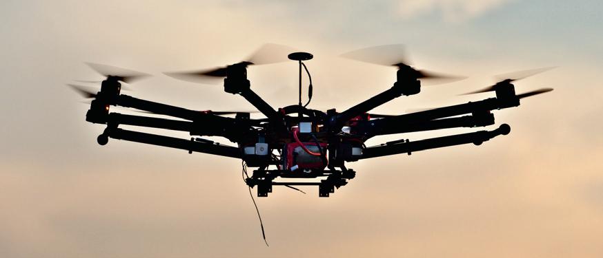
Unmanned aerial vehicles (UAVs) were originally used for military purposes, but their scope has since widened. They are now used for rescue operations or emergency man agement and can also perform the function
of repeaters. UAVs must therefore transmit a large amount of information quickly and efficiently. The next generation networks — 5G and 6G — can satisfy such a request. They work on New Radio technology with a wavelength of millimetre range. However, such waves have a drawback — any object can be an obstacle for them and break the connection.

Vyacheslav Begishev, PhD and Associ ate Professor at RUDN University, said that UAVs are expected to use 5G/6G networks, with the new NR technology operating in the millimetre frequency range to sup port services such as video surveillance. However, Begishev notes that buildings can get in the way of direct connection between base stations and UAVs, leading to connection failures.
To address the issue, mathematicians at RUDN University calculated the probability of blockage by an obstacle. It was possible to express it through the parameters of the deployed system — the width of the streets, the height of the stations and the height of the UAV flight. The mathematicians conducted numerical experiments and found out which parameter affects the reliability of the connection more than others and how it can be improved.
One possible way to reduce the probability of a break is to place base stations on the roofs of buildings, with the mathematicians showing that the station located on the roof is approximately equal in efficiency to 6–12 ground stations. The exact estimate will be different for each system depending on the given parameters. Most of all, the probability of a drop was affected by the width of the street. For example, a width of 20 metres reduced the likelihood of blockage by 50% compared to a width of 10 metres, all other things being equal.
“We foresee two areas of application of the proposed model. The first concerns cases where it is necessary to use simple models to determine the probability of block ing. In addition, the model can be used to estimate the required base station density for a given blocking probability. Moreover, the accuracy of the model increases with an increase in the deployment area. That is, it can be applied to large urban areas,” said Konstantin Samuilov, Doctor of Sci ence in Technical Sciences, Director of the Institute of Applied Mathematics and Telecommunications at RUDN University.
WWW.ELECTRONICSONLINE.NET.AU NOVEMBER/DECEMBER 2022 21
RELIABILITY
iStock.com/XH4D
Ricoh chooses u-blox module for
GNSS performance
u-blox, a provider of positioning and wireless communication technologies and services, has integrated its ZOE-M8B GNSS (global navigation satellite system) module into the new RICOH THETA X. Ricoh’s camera allows users to shoot 360-degree spherical images and videos in one click and to visualise them immediately on a large LCD touch panel.
The u-blox ZOE-M8B enables the RICOH THETA X’s built-in GPS. The GPS (QZSS) and A-GPS automatically embed accurate location information to each image taken without the need for a smartphone or another external device. An icon on the LCD touch panel displays the availability of the GPS signals depending on the user’s location, so that the location information can be acquired before starting shooting. This new function is designed to enhance the THETA X’s location accuracy down to a five-metre radius and is therefore suitable for a range of industrial and consumer applications. It is for instance a suitable tool for the construction and architecture professions — which can digitise sites through 360-degree scenery imagery and capture any project phase — as well as for the mapping industry, insurance providers and realtors.

The u-blox module is a small (4.5 x 4.5 x 1.0 mm) systemin-package (SiP) GNSS module offering positioning with concurrent reception of up to three satellite constellations. The Super-E (Super-Efficient) mode provides power consumption as low as 12 mW, and built-in SAW and LNA make it suitable for passive antennas.
“We chose to integrate the u-blox ZOE-M8B GNSS module into our THETA X because of the highly accurate location information it offers, alongside easy integration thanks to its small size and low power consumption. In other words, the module offers what we needed in terms of a small antenna design whilst not compromising on highly accurate positioning performance — a function essential to our customers,” said Kenji Daigo, GPS Function Developer for THETA X at Ricoh. u-blox Singapore Pte Ltd www.u-blox.com
MULTI-PROTOCOL BLE MODULES
Mouser Electronics, Inc. now stocks the BL5340 multi-core multi-protocol Bluetooth modules from Laird Con nectivity. Featuring the Nordic Semi conductor nRF5340 system-on-chip (SoC), the modules include a dualcore Arm Cortex-M33 microcontroller to support wireless connectivity and end applications.
The BL5340 modules, available from Mouser Electronic, highlight the hardware capabilities of the nRF5340 SoC, including support for Bluetooth 5.2 Low Energy, 802.15.4 (Thread and Zigbee) and NFC. The Cortex-M33 mi crocontroller includes two cores, each supporting their own power manage ment system, enabling designers to use one core solely for wireless operations and the other for application needs.
The modules come with enhanced security from Arm TrustZone, Arm CryptoCell-312 and more. Other fea tures include USB access, random number generator, temperature sensor, inter-processor communication and watchdog timer. The modules include integrated PCB antenna options for overall design simplicity or trace pin variants for connecting external anten nas. The modules support power supply from 1.7 to 5.5 V and offer low-power performance with consumption of 5.1 mA transmit and 2.7 mA receive.
Mouser also offers the DVK-BL5340 development kits, which provide a platform for rapid wireless connectiv ity prototyping, making it possible for customers to test and validate the mod ule’s hardware interfaces. To enable development flexibility, the modules support programming via the Nordic nRFConnect SDK and Zephyr RTOS.
The modules come certified to FCC, CE, ISED, RCM, MIC, UKCA and Bluetooth SIG, and support applica tions such as asset tracking, smart buildings, secure medical peripherals and industrial automation.
Mouser Electronics au.mouser.com
22 NOVEMBER/DECEMBER 2022 WWW.ELECTRONICSONLINE.NET.AU
long-lasting
Image credit: u-blox
JUNCTION SLAVE MODULE

ICP Australia has introduced the ICP DAS ECAT-2517, an 8-port EtherCAT junction slave module. The module is designed for realising flexible wiring by daisy chain and branch. The device cannot be used as a standard Ethernet switch. The module has an input range of +10 to +30 VDC, with the consumption range being 0.23 A at 24 VDC, allowing the module to function optimally, per industry standards. The construction of the module is metal so it can endure tough operating conditions.
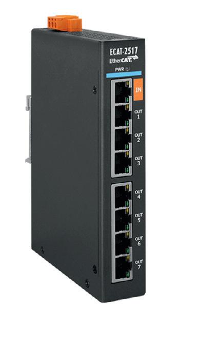
The module is also compact, measuring 28 x 154 x 110 mm, so that it can fit in space constraint ap plications. The module comes with a DIN-Rail installation option, making it user-friendly. The module is also designed to survive extreme temperatures with its operating temperature ranging from –25 to +75°C, making the module an asset in tough industrial environments.


Key features include powerful MCU that can handle efficient network traffic and ESD Protection 4 kV con tact for each port. The device features 100BASE-TX with a maximum distance between stations up to 100 m. The device is also EtherCAT conformance test tool verified.
ICP Electronics Australia Pty Ltd www.icp-australia.com.au


PANEL PC
Backplane Systems Technology now offers IBASE’s BYTEM-101-PC, which is an allin-one 10.1 ″ panel PC with an Intel Atom processor. The panel PC has low power consumption, making it cost-effective and viable.

The panel PC has a flat panel design with a projected capacitive display with IP65 front-panel waterproof protection that enables the panel PC to survive tough environments, where there is dust or exposure from splashes and low-pressure jets. The panel PC is constructed from aluminium and can withstand temperatures ranging from 0 to 40°C, allowing it to take on tough conditions.


The panel PC also has accessible storage and internal expansion; one mPCI-E(x1) comes with a USB signal and one mSATA/mPCI-E(x1) comes with a USB signal and mSATA supports. The panel PC also supports a VESA mount to enhance user experience; it is also compact, allowing it to be deployed in applications where there are space constraints.
The panel PC features a fanless design, with a 9–30 V DC wide-range power input.
Backplane Systems Technology Pty Ltd www.backplane.com.au
WWW.ELECTRONICSONLINE.NET.AU NOVEMBER/DECEMBER 2022 23 ROLEC OKW Australia New Zealand Pty Ltd Unit 6/29 Coombes Drive, Penrith NSW 2750 ENCLOSURES AND TUNING KNOBS FOR TODAY‘S ELECTRONICS EQUIPMENT!
+61 2 4722 3388 E-Mail: sales@rolec-okw.com.au
www.okw.com.au Phone:
DEAD RECKONING MODULE
The u-blox F9 GNSS technology platform provides high loca tion accuracy. Designed to serve mass market industrial and automotive applications, the F9 platform combines multi-band global navigation satellite system (GNSS) technology with dead reckoning and high precision algorithms, and is compatible with a variety of GNSS correction data services to achieve accuracy down to the centimetre level.
The F9 platform is designed to deliver a fast time to first fix (TTFF) by using multi-band (L1/L2/L5) GNSS signals to provide robustness against interference and errors caused by ionospheric effects. By concurrently receiving signals from four GNSS constellations (GPS, GLONASS, Galileo, BeiDou), it lever ages a range of satellite signals to increase the availability of high-precision positioning even in difficult urban environments. Using a multi-band real-time kinematic (RTK) correction service and an embedded RTK algorithm, the platform is designed to achieve centimetre-level accuracy with an RTK update rate of up to 20 Hz.
OPEN FUSE HOLDER
The SCHURTER OGN series open fuse holder for 5 x 20 mm fuses is a compact high-performance fuse holder. The series now offers a version that is compatible with Through-Hole Reflow (THR) solder processes, in addition to the existing THT and SMT versions.
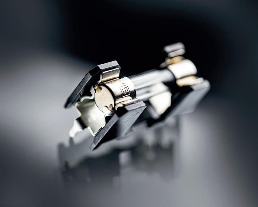


SMT components are used for PCB assemblies. Ideally, these components are compatible with solder reflow processes to fully automate the assembly. While THT components offer a board mounted solution, they are typically not designed for the rigors of a reflow process. In these cases, a second solder ing step is necessary. The additional manual step required for THT assembly is time-consuming and allows additional margin for error.
The F9 platform includes built-in jamming and spoofing detection systems that protect against intentional and unin tentional interference. Dead reckoning technology based on inertial sensors extends high-precision performance to otherwise challenging urban environments.

u-blox Singapore Pte Ltd www.u-blox.com
The solution is THR components, combining the features of PCB THT mounting with a component capable of withstanding the high thermal stress of a reflow oven. The THR component is first printed into the pin vias, and then pushed through the solder paste. As the paste melts in the reflow oven, the liquid solder retracts into the vias, due to wetting and capillary forces, to form the solder joint.
As with existing OGN series open fuse holders, the OGN THR is designed for various types of 5 x 20 mm fuses. The series is rated 16 A at 500 VAC/VDC according to UL and CSA and 10/16 A at 500 VAC according to VDE. The series can be enclosed with an optional cover. Rated power acceptance according to IEC is 4 W/16 A at Ta 23°C for the version without cover. A black cover offers a power acceptance of 4 W/10 A and a transparent cover is approved at 2.5 W/10 A. Admis sible ambient air temperature range is –40 to 85°C. The OGN series also complies with enhanced fire safety requirements and features glow wire resistance according to IEC 60335-1. The OGN THR is fully backwards compatible with the OGN THT. SCHURTER (S) PTE LTD www.schurter.com
24 NOVEMBER/DECEMBER 2022 WWW.ELECTRONICSONLINE.NET.AU
Bayswater
Accredited testing and global product approvals since 1992
MINIATURE COLD-ATOM INERTIAL SENSORS
A quantum inertial sensor is designed to measure motion more accurately than devices that help navigate missiles, aircraft and drones. However, its delicate array of components that includes a laser and vacuum system has kept the technology grounded and confined to the controlled settings of a lab.

Atomic physicist Jongmin Lee, part of a team at Sandia National Laboratories, aims to reengineer the sensor into a compact, rugged device that can safely guide vehicles where GPS signals are jammed or lost.
The research team has built a cold-atom interferometer, a core component of quantum sensors, designed to be smaller and tougher than typical lab set-ups. The prototype was described in Nature Communications, with researchers showing how to integrate sev eral normally separated components into a single monolithic structure. In doing so, the researchers reduced the key components of a system that existed on a large optical table down to a sturdy package roughly the size of a shoebox. The paper also describes a roadmap for further miniaturising the sys tem using technologies under development.
“Very high sensitivity has been demon strated in the lab, but the practical matters are, for real-world application, that people need to shrink down the size, weight and power, and then overcome various issues in a dynamic environment,” Lee said.
The prototype demonstrates the strides taken towards moving advanced navigation
technology out of the lab and into vehicles on the ground, underground, in the air and even in space. As a jet does a barrel roll through the sky, current onboard naviga tion technology can measure the aircraft’s tilts, turns and accelerations to calculate its position without GPS, for a time. Small measurement errors gradually push a vehi cle off course unless it periodically syncs with the satellites. Quantum sensing would operate in the same way, but the improved accuracy would mean onboard navigation wouldn’t need to cross-check its calcula tions as often, reducing its reliance on satellite systems.
Roger Ding, a postdoctoral researcher on the project, said that in principle, there are no manufacturing variations and calibrations, compared to conventional sensors that can change over time and require recalibration. Aaron Ison, the lead engineer on the project, said to prepare the atom interferometer for a dynamic environment, the team used materi als suitable for extreme environments. Parts that are normally separate and freestanding were integrated together and fixed in place, or built with manual lockout mechanisms. “A monolithic structure having as few bolted
interfaces as possible was key to creating a more rugged atom interferometer struc ture,” Ison said.
The team used calculations called fi nite element analysis to predict that any deformation of the system in conventional environments would fall within required allowances. “The overall small, compact design naturally leads towards a stiffer more robust structure,” Ison said.
Most modern atom interferometry experi ments use a system of lasers mounted to a large optical table for stability reasons. While Sandia’s device is comparatively compact, the team has also devised further design improvements to make the sensors smaller using integrated photonic technologies. “There are tens to hundreds of elements that can be placed on a chip smaller than a penny,” said Peter Schwindt, the principal investigator on the project.
In their paper, the researchers outlined a future design in which most of their laser set-up is replaced by a single photonic integrated circuit, about eight millimetres on each side. Integrating the optical com ponents into a circuit would make the atom interferometer smaller and more rugged, by fixing the components in place. While the researchers can’t do this yet, the necessary technologies are in development at Sandia. Lee said that integrated photonic circuits would lower costs and improve scalability for future manufacturing. “Sandia has shown an ambitious vision for the future of quantum sensing in navigation,” Lee said.
WWW.ELECTRONICSONLINE.NET.AU NOVEMBER/DECEMBER 2022 25
iStock.com/ismagilov NAVIGATION
HELP
NAVIGATION WITHOUT GPS
Q&A WITH MARK BURR-LONNON

To date, Mouser has received 28 business awards from its manufacturer partners during 2021 and 2022, recognising bestin-class global logistics among other things. Was this the result of a particular strategy on Mouser’s part, or just business as usual?
It is never “business as usual” for Mouser Electronics — we work to deliver on the high standards that our customers have come to expect from us. Mouser is an authorized distributor for more than 1,200 manufacturer brands, with a focus on stocking the widest selection of semiconductors and electronic components — in stock, and ready to ship. Mouser’s customers can expect 100% certified, genuine products that are fully traceable from each of its manufacturer partners. Mouser’s strategy has been to invest in inventory regardless of business conditions. This positions us well to absorb disruptions, of which today there are many, and ensure business continuity for our customers.
Besides supply assurance, Mouser’s core value proposition is the rapid introduction of new products and technologies irrespective of market challenges. As the world’s leading semiconductor and electronic component distributor focused on New Product Introductions from its leading manufacturer partners, Mouser continues to introduce new products and alternatives to support innovation from the engineering and design community.
Mouser has invested heavily in state-of-the-art automation in the global distribution centre, which features the world’s largest installation of vertical lift modules, with automated extractors to bring the components to the employee workstations, plus a variety of automated packaging systems for sealing and labelling shipments. The state-of-the-art automation enables processing up to 14 orders per minute, which, in turn helps our customers gain the edge they need to reduce their time-to-market.
We understand that buyers need to easily find the right information on products and applications, and to this end we have created a Technical Resource Centre to help speed customers’ designs. Over half of our business today comes via the internet, so we continue to expand mouser.com with search enhancements, buying tools and technical resources for buyers and engineers. Overall, Mouser has strong engineering design support and buyer focus aimed at serving the global electronic design engineer and buyer communities.
26 NOVEMBER/DECEMBER 2022 WWW.ELECTRONICSONLINE.NET.AU
SPONSORED CONTENT
Mark Burr-Lonnon, Senior Vice President of Global Service & EMEA and APAC Business, Mouser Electronics
A recent report from IDC found that worldwide semiconductor revenue is expected to reach a whopping US$661 billion in 2022, up 13.7% from 2021. Have you noticed this increased demand in your business, and what industries/applications do you think are driving it?
The use of electronic devices and systems is exceptionally strong worldwide as we are still shipping hundreds of thousands of components daily. Manufacturers and distributors worldwide are facing a challenge to keep up with the rising demand for semiconductors. A large part of the demand is being driven by the industrial and automotive sectors. Leading technologies like 5G, Industry 4.0, artificial intelligence, robotics, industrial automation, transportation, power management, and home automation are expected to drive demand as they keep transforming our industries, homes and cities well into the next decade and beyond. There are exciting developments in new sensor technologies from our manufacturers, as well as in power management and microprocessors. We also expect to see an increased need for components for 5G phones, game consoles, wearables, data centres, and wireless, mobile and telecommunications-related devices. Mouser continuously adds new manufacturers and new product offerings and is the fastestgrowing distributor in our industry. We are committed to being the industry’s one-stop source for the board-level components and development tools needed for complete project designs.
Are electronics distributors still noticing supply chain issues as a result of the pandemic, and are you expecting further shortages due to the war in Ukraine? How are you adjusting to these disruptions? The pandemic severely disrupted manufacturing across many industries, and some supply chains across the globe remain in a state of flux. Distributors are not immune to global market conditions, and there have been extended lead times and restricted allocation on some product lines. Mouser has weathered these challenges through a variety of approaches and closely monitors supply and demand while working to stock inventory for customers.
With our wide breadth of inventory — including many alternate products — we can help customers weather supply chain instabilities. We have approximately 1 million part numbers in stock, giving design engineers a wide range of choices for their upcoming prototypes. Customers rely on us because they know we are a well-resourced, authorized distributor with the widest product selection in the industry. Our strategy remains to invest in inventory and today we have over $1 billion of inventory available to ship.
With many workers taking sick leave over winter due to COVID and flu, how important is automation to keeping factories and similar environments going, and how has Mouser serviced this sector?

Automation is a business imperative today, regardless of disruptions and uncertainty. From the earliest attempts of James Watt in 1788, industry has constantly strived for greater control and automation on the factory floor. With the confluence of a host of emergent technologies, Industry 4.0 and smart manufacturing offer new modes of autonomous corrective feedback in factory machines and systems. Autonomous intelligent machines deliver higher accuracy and allow mass customization while ensuring greater safety. Organizations can thus gain more strategic value from the greater process efficiencies and higher productivity.
All this has become possible due to advances in sensor technologies, PLCs, power management systems, microprocessors, and wireless and mobile communications. Mouser stocks a wide inventory of the latest offerings of PLCs, sensors, actuators, switchgears, connectors and other components and devices that cater to the automation industry.
Finally, for businesses who are dealing with rising costs due to inflation, do you have any tips on how the smart deployment of electronic components can have a positive impact on the bottom line?
With inflationary pressures continuing, it looks like the industry can expect to see continued price increases for in-demand products. Prices will likely stabilize when lead times get back to normal. At Mouser, we are working directly with our manufacturers to minimize any impact for customers. Planning and ordering in advance for popular product lines that require regular replenishment can help. Mouser’s depth of inventory, extensive logistic support and state-of-the-art shipping and delivery can bring reassurance to customers. Our transparent pricing policy helps to maintain steady prices, even in volatile markets. I believe that despite the current instabilities and pressures, there are reasons for optimism and confidence as we look ahead to the future of the industry. Innovation is still happening and some of the major growth drivers are 5G, artificial intelligence, robotics, industrial automation and transportation.
WWW.ELECTRONICSONLINE.NET.AU NOVEMBER/DECEMBER 2022 27
Mouser
Electronics au.mouser.com Image credit: Mouser Electronics
DIN-RAIL MOUNT ADAPTOR KITS FOR PANEL MOUNT FILTERS
SCHURTER DIN-Rail mount adaptor kits provide a simple solution for converting panel mount block filters to DIN-Rail mount for use inside control cabinets. Simply affix the clip to the filter using the screws provided in the kit, then snap the converted filter onto the DIN-Rail.
Panel mount block filters are commonly used in equipment to filter interferences that are potentially harmful to the operation of the equipment and other equipment nearby. With more applications using intelligent devices emerging in the industrial market, the need for EMC filters is also increasing, although identifying and sourcing DIN-Rail mount types for use in control cabinets can be a challenge. Like DIN-Rail adaptors for other types of products, SCHURTER’s DIN-Rail adaptor kit addresses this need with a simple design for quick and easy installation.
Sustaining a good ground connection is carefully considered in the clip design, which uses heavy-duty metal for a constant ground connection of the filter housing to the rail. The DIN-Rail mount adapter kit fits with SCHURTER’s compact range of EMC filter series: FMAB NEO, FMAB HV, FMBB NEO, FMBB EP and FMAD CP. It is also suitable for use with other panel mount filters, provided the mounting holes are the same.
SCHURTER (S) PTE LTD www.schurter.com
ANTENNA TEST CHAMBER
The R&S ATS1500C antenna test system from Rohde & Schwarz now offers an added temperature test option and feed antenna, enabling temperature-controlled measure ments in a wide temperature range as well as parallel access to both polarisations, increasing test efficiency and flexibility. The compact antenna test range (CATR)-based antenna test chamber is carefully designed to eliminate ghost targets within the chamber during target simulation tests and includes a positioner for angular measurements.
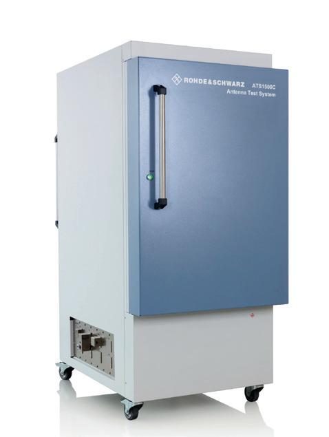
The R&S ARC-TEMP temperature test option cre ates a temperature-controlled environment for the radar under test and supports a wide range from -40 to +85°C. The heated or cooled air is provided by an external thermal air stream system that supplies the air to the temperature bubble mounted on the positioner. This changes the temperature without affecting the chamber’s measurement performance. This feature makes it possible to automate measurements at different temperatures without a separate climatic chamber, which increases radar testing speed.
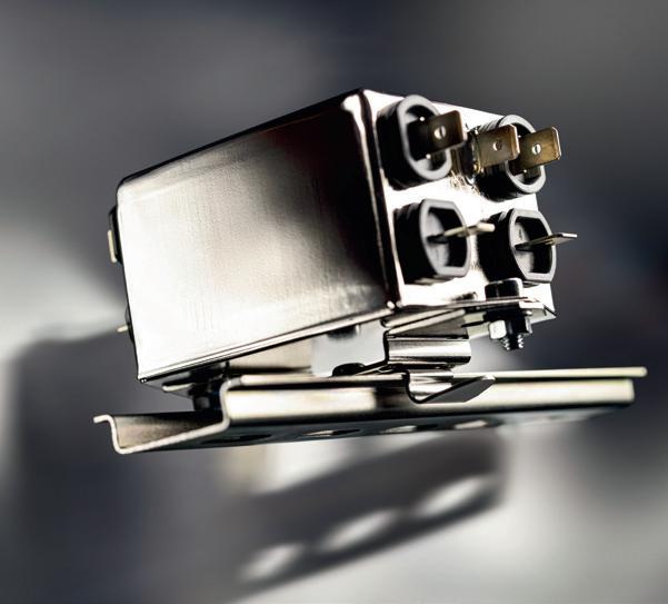
The R&S ARC-FX90 universal feed antenna, which supports 60 to 90 GHz, can be added to the test chamber. The antenna includes an orthomode transducer, which enables parallel access to vertical and horizontal polarisations.
With these options for the test chamber, developers can efficiently character ise RF transmitters, calibrate antenna manifolds, measure antenna patterns, test robustness against interference, check compliance with regulations such as ETSI and FCC, and plan testing and calibration procedures for later mass production. The chamber is used as a reference environment before porting the procedures to a production tester.
The test chamber can be used for automotive radar module development, validation, calibration and compliance testing. The universal feed antenna and temperature test option are both hardware extensions to the R&S ATS1500C and can be retrofitted. Rohde & Schwarz (Australia) Pty Ltd www.rohde-schwarz.com.au
HANDHELD INSTRUMENT HOUSING
Hammond’s IP54 sealed general-pur pose 1593 ABS family general-purpose handheld instrument housing has a number of options as standard. 15 sizes, from 60 x 105 x 35 mm to 140 x 66 x 28 mm, are all available in three colours, black, grey or translucent blue. There’s even a size optimised for use as a card reader. Variants with two end panels, or one end panel and an integral battery compartment, plus options of plain or contoured plastic panels, IR transpar ent panels or plain aluminium panels make the 1593 one of Hammond’s most versatile families.
Key features include: ergonomic design; 15 sizes: 60 x 105 x 35 mm to 140 x 66 x 28 mm; membrane keypad or display recess; nine sizes with two end panels; five sizes with one end panel and a battery compartment; one size (1593J, 66 x 66 x 28 mm) without end panels; the 1593N, 109 x 74 x 25 mm accepts many card readers; plain plastic panels for 14 sizes; sculptured plastic panels for five sizes; plain alu minium panels for 14 sizes; infra-red transparent panels for 12 sizes; moulded in general-purpose ABS with a satin finish; construction gives IP54 sealing; available in grey, black and translucent blue; belt clip accessory.
Hammond Electronics Pty Ltd www.hammfg.com
28 NOVEMBER/DECEMBER 2022 WWW.ELECTRONICSONLINE.NET.AU
WHAT’S THE DIFFERENCE BETWEEN TRADITIONAL RESINS AND BIO-BASED RESINS?
 Beth Massey and Beth Turner
Two of Electrolube’s leading resin specialists have collaborated to give readers the clearest focus on how introducing bio-based resins systems will impact production processes and the benefits they bring in terms of performance.
Beth Turner is Electrolube’s Senior Technical Specialist and Beth Massey is Electrolube’s Global Product Manager for Resins. Hav ing two Beths working on resins may be a little confusing, but this column should help demonstrate the different input each party has and alleviate any confusion. We are going to dive deeper into Electrolube’s new range of bio-based resins and explore how they differ from traditional resins, aside from their obvious sustainable and environmentally friendly benefits.
WWW.ELECTRONICSONLINE.NET.AU NOVEMBER/DECEMBER 2022 29
COATINGS
iStock.com/JeanRee
COATINGS
What percentage of the overall content can reasonably be bio-based without causing a detrimental effect to the performance of the product, and is the bio content added to part A or B?
The honest answer to this question is quite simply it depends. Realistically up to 70% of content can be bio-based, and both A and B can contain bio-based materials. The 70% limit is more to do with availability of bio-based alternatives than due to high levels having a detrimental effect. It’s likely that some components of the formulation will never have a bio-based alternative, but the benefits we are seeing from changing to bio-based raw materials where possible do suggest we should push to include as high a content as possible. It goes without saying that bio-coatings have significantly less impact on the environment and meet the ethical needs of manufacturers and end users. However, the most surprising benefit observed has been the improvement in terms of performance. Even additives such as powders can be bio-based.
Does a particular chemistry, ie, epoxy or PU lend itself to removing some of the chemicals present and substituting them for bio-based content? If yes, why is this?
Both are suited. If we refer to Beth Turner’s award-winning white paper on next-generation bio-resins, Turner states, “Nature offers an abundance of macro molecules and smaller molecular weight compounds that provide renewable sources for polymers, as opposed to crude oil. These renewable resources make ideal structural backbones for the synthesis of biopolymers, renewable-based monomers, fillers and additives, the key ingredients for polyurethane and epoxy thermoset materials. Research and development to promote innovative solutions that lead to a sustainable economy shows that bio-based materials can deliver a viable alternative to materials derived from crude oil, even in electronic encapsulation applications.”
Interestingly, bio-based resins show the same dispensing behaviour and cure profiles as conventional resins, so there is no need to invest in adaptive equipment. There is no negative effect on processability or curing from using bio-based materials and perfor mance is equivalent. However, we do see significant benefits in cured properties when select bio-based raw materials are used. Combining a bio-based polymer matrix and hardener with a biogenic filler offers a sig nificant improvement in thermal conductivity
to a fully synthetic polyurethane using a synthetic polymer matrix derived from crude oil and mineral rock filler. The bio-based resin also offers better electrical

insulation and thermal stability while also having a higher resistance to hydrolysis vs a synthetic polyurethane resin.
Initial interest is often sparked because of the increasing focus on sustainability but this is then extended by research that has shown significant performance benefits for bio-based resins. The best way to succeed with bio-based products is to ensure consum ers do not have to compromise on quality in order to make the more sustainable choice. As was documented in Beth Turner’s white paper, use of certain bio-based raw materials offers substantial benefits in terms of the cured resin’s electrical and thermal perfor mance vs synthetic based raw materials. The fact that these high-performance bio-based
30 NOVEMBER/DECEMBER 2022 WWW.ELECTRONICSONLINE.NET.AU
Do bio-based resins behave in a different way when being poured or when curing compared to their chemical versions, and are the tech data sheets almost identical in terms of the qualities exhibited?
compared
Are bio-based products gaining popularity purely due to their association with sustainability or do they exhibit qualities that are superior to their chemical alternatives?
BIO-COATINGS HAVE SIGNIFICANTLY LESS IMPACT ON THE ENVIRONMENT AND MEET THE ETHICAL NEEDS OF MANUFACTURERS AND END USERS.
materials are a more sustainable solution is really an added bonus. It’s especially exciting that some of the raw materials tested were from biogenic waste, adding another layer of sustainability by repurposing waste material from other industries.
In your experience, is sustainability something that genuinely affects manufacturers and their reputation in the market as doing their absolute best to reduce their carbon footprint, or is this more of a box-ticking exercise?


I think we are seeing a sea change in attitude at the moment, from sustainability having been seen as a niche focus area to now being a big concern for society as a whole. In the past, the focus has almost been on sustainability as a marketing tool, leading to ‘greenwashing’, but more and more manu facturers are realising that sustainability

needs to be at the core of what they do, both to meet increasing consumer demands for sustainable products and to future-proof their business. We’ve seen supply short ages and price volatility making synthetic materials, such as those derived from crude oil, a much less attractive choice, which adds an additional commercial incentive towards using more sustainable bio-based materials. The fact that our research shows using certain bio-based materials in the formulation improves resin properties also means a bio-based resin doesn’t need to be sold on sustainability credentials alone, its performance speaks for itself, as can be seen with our UR5645 high temperature, chemically resistant polyurethane resin.
Electrolube’s extensive research and findings conclude that the future looks extremely promising for bio-based resins, which bring distinct performance advan tages in harsh environments, including underwater applications as well as hot and humid operating environments. Bio-based chemicals are highly suited to a wide va
riety of applications within the electronics industry and even lend themselves to RF applications. Electrolube’s UR5645 has a bio-sourced content of over 60% and has been used in many sensor applications. It is likely that the bio-based chemical share within the electrochemical production seg ment will increase, and electrochemical manufacturers and associated OEMs will become an important part of the bio-economy of the future. Please contact our Technical Support team to learn more about how bio-based resins can be implemented into your application.
Electrolube www.electrolube.com.au
WWW.ELECTRONICSONLINE.NET.AU NOVEMBER/DECEMBER 2022 31
Beth Massey Beth Turner
iStock.com/Adrian Pacurariu COATINGS
to industry and business professionals


The magazine you are reading is just one of 11 published by Westwick-Farrow Media. To receive your free subscription (magazine and eNewsletter), visit the link below.


www.WFMedia.com.au/subscribe FREE
NANOCOMPOSITE FILMS USED TO KEEP THIN ELECTRONICS COOL

Heat dissipation is essential for maintaining the performance of electronic devices; however, efficient heat dissipation is a concern for thin-film electronics, as conventional heat sinks are bulky and cannot be integrated into them. Thus, there is a need for thermal diffusion materials that are thin and flexible and can be implemented in thin-film devices for efficient heat dissipation.
Researchers from Japan have found that using sea squirts or ascidians can help solve this problem. The researchers prepared flexible na nocomposite films using an ascidian-derived cellulose nanofibre matrix and carbon fibre fillers — the prepared films demonstrated “excellent” anisotropic in-plane heat con duction and the carbon fibre fillers inside are reusable.
Currently, several substrate materials can act as heat diffusers as thin films, but most diffuse heat in the in-plane direction isotropically. This could create thermal inter ference with the neighbouring components of a device. Junior Associate Professor Kojiro Uetani from the Tokyo University of Science (TUS) said that for substrates on which multiple devices are mounted in high density, it is necessary to control the direc tion of thermal diffusion and find an effective heat removal path while thermally insulating between the devices. “The development of substrate films with high anisotropy in inplane thermal conductivity is, therefore, an important target,” said Uetani.
In a recent study published in ACS Ap plied Materials & Interfaces , Uetani and his team, comprising Assistant Professor Shota Tsuneyasu from the National Institute of Technology, Oita College, and Professor Toshifumi Satoh from Tokyo Polytechnic
University, reported a newly developed nano composite film made of cellulose nanofibres and carbon fibre-fillers that demonstrated in-plane anisotropic thermal conductivity. Many polymer composites with thermally conductive fillers have been proposed to enhance thermal conductivity; however, there are few reports on materials with particu late or plate-like fillers that exhibit thermal conductivity anisotropy, which is important to prevent thermal interference between adjacent devices. Fibrous fillers such as carbon fibres (CF), however, can provide in-place anisotropy in two-dimensional materials due to their structural anisotropy.
It is important to select matrices with high thermal conductivity. Cellulose nanofibres (CNFs) extracted from the mantle of ascid ians have been reported to exhibit higher thermal conductivity (about 2.5 W/mK) than conventional polymers, making it suitable for use as a heat-dissipating material. Cellulose has a high affinity for carbon materials and is easy to combine with CF fillers. For exam ple, hydrophobic CF cannot be dispersed in water by itself, but in the presence of CNF, it is easily dispersed in water. Accordingly, the researchers chose bio-based ascidian derived CNFs as the matrix.
For material synthesis, the team prepared an aqueous suspension of CFs and CNFs and then used a technique called liquid
3D patterning. The process resulted in a nanocomposite consisting of a cellulose matrix with uniaxially aligned carbon fibres. To test the thermal conductivity of the films, the researchers used laser-spot periodic heating radiation thermometry and found that the material showed a high in-plane thermal conductivity anisotropy of 433% along with conductivity of 7.8 W/mK in the aligned direction and 1.8 W/mK in the inplane orthogonal direction.
The researchers also installed a powder electroluminescent (EL) device on a CF/CNF film to demonstrate the effective heat dis sipation. In addition, the nanocomposite film could cool two closely placed pseudo heat sources without any thermal interference. Another major advantage of the CF/CNF films is their recyclability. The researchers were able to extract the CFs by burning the cellulose matrix, allowing them to be reused.
Overall, these findings can act as a framework for designing 2D films with novel heat-dissipating patterns and can also en courage sustainability in the process. “The waste that we humans generate has a huge environmental impact. Heat transfer fillers, in particular, are often specialised and expensive materials. As a result, we wanted to create a material that does not go to waste after usage but can be recovered and reused for further applications,” Uetani said.
WWW.ELECTRONICSONLINE.NET.AU NOVEMBER/DECEMBER 2022 33
iStock.com/scanrail
HEAT DISSIPATION
AUSTRALIAN SOLAR PIONEER
Scientia Professor Martin Green from the University of New South Wales, Sydney, has received the 2022 Millennium Technology Prize for his innovation that transformed the production of solar energy. The ¤1 million award for technology, conferred every two years, recognised Green’s leadership in the development of the Passivated Emitter and Rear Cell (PERC). Since its development in 1983, the PERC has reportedly become one of the most commercially viable and efficient silicon solar cell technologies for use in solar panels and for large-scale electricity production.
Green developed the PERC by improving the quality of both the top and rear sur face of standard silicon solar cells. When sunlight — in the form of particles called photons — enters a cell, it excites the electrons within the silicon. In this excited state, electrons can move through the cell, creating an electric current. The improved surface of the PERC allows the electrons to maintain this excited state — or move freely — for longer, resulting in greater and more efficient energy generation. The PERC has helped increase the conversion efficiency of standard solar cells by over 50% in relative terms from 16.5% in the early 1980s to 25% in the early 2000s.
The innovation has also reduced the costs of using solar panels, making solar energy more affordable than fossil-based alterna tives. PERCs can also provide an energy supply to homes without them needing to be connected to a grid, thereby providing a reli able power supply for remote communities. Professor Green said that the prize not only

recognised his contribution to photovolta ics (the conversion of light into electrical power), but also the achievements of his students and research colleagues at UNSW, as well as those of the broader photovoltaic research and commercial community.
“I believe the Prize will increase my cred ibility as a spokesperson for what needs to be done to address climate change. We need to switch from fossil fuels to renewable energy to sustain the trajectory of human civilisation on our shared planet. The pace of change is accelerating and the world will shift to solar and wind energy over the coming decade. I believe a huge transformation of historic significance is underway,” Green said.
Green and his team are working on com bined cell technologies to reach 40% solar cell efficiency by exploring options such as stacking cells on top of each other. “Solar cells are increasingly being used to replace large power stations that use fossil fuels. In 2021, 20 countries or regions generated 8% to 25% of their total electricity supply from solar energy, with this number growing quickly. The rapid cost reductions in solar energy that my work has facilitated have come just in time, right at the point when the importance of acting immediately to address climate change has become overwhelmingly obvious,” Green said.
Professor Päivi Törmä, Chair of the In ternational Selection Committee of the Mil lennium Technology Prize, said: “PERCs can help us provide low-cost energy solutions and mitigate climate change. Continued research on solar cells is needed to replace their constituents that have limited supply, such as silver, with more abundant alternatives.”
Westwick-Farrow Media A.B.N. 22 152 305 336 www.wfmedia.com.au
Head Office
Unit 7, 6-8 Byfield Street, North Ryde Locked Bag 2226, North Ryde BC NSW 1670 Ph: +61 2 9168 2500
Senior Editor Lauren Davis Editor Ashna Mehta wnie@wfmedia.com.au
Publishing Director/MD Geoff Hird
Art Director/Production Manager Julie Wright
Art/Production Linda Klobusiak Circulation Dianna Alberry circulation@wfmedia.com.au
Copy Control Mitchie Mullins copy@wfmedia.com.au
Advertising Sales Account Manager
Sandra Romanin – 0414 558 464 sromanin@wfmedia.com.au
Asia Tim Thompson - 0421 623 958 tthompson@wfmedia.com.au
If you have any queries regarding our privacy policy please email privacy@westwick-farrow.com.au
Printed and bound by Dynamite Printing Print Post Approved PP100007394 ISSN No. 0728-3873
All material published in this magazine is published in good faith and every care is taken to accurately relay information provided to us. Readers are advised by the publishers to ensure that all necessary safety devices and precautions are installed and safe working procedures adopted before the use of any equipment found or purchased through the information we provide. Further, all performance criteria was provided by the representative company concerned and any dispute should be referred to them. Information indicating that products are made in Australia or New Zealand is supplied by the source company. Westwick-Farrow Pty Ltd does not quantify the amount of local content or the accuracy of the statement made by the source.
34 NOVEMBER/DECEMBER 2022 WWW.ELECTRONICSONLINE.NET.AU
YEARS CELEBRATING
iStock.com/SimonSkafar
SOLAR CELLS
RECEIVES EUROPEAN INNOVATION PRIZE