10 minute read
CAE Solutions


Preview design changes in real time
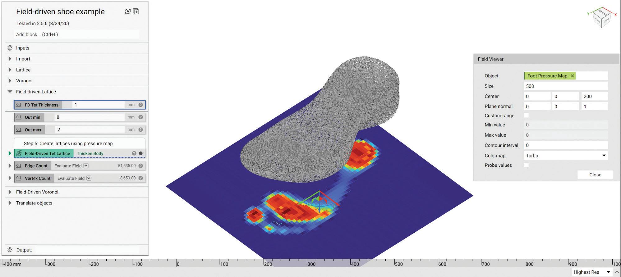
The 3.0 version of the nTopology
so ware off ers several enhancements. One of the new features is an opt-in GPU acceleration that will deliver a 10x to 100x performance boost, which makes it easier to preview design changes in realtime and regenerate parts with complex geometry in seconds. The so ware also consolidates recent technology improvements introduced to it. These include functional latticing workfl ows, topology optimization tools, engineering simulation utilities, and advanced design automation capabilities. The core of version 3.0 is the implicit modeling engine. This engine describes every solid body by a single mathematical equation, which enables designers to generate complex part geometry reliably and error- ee. Any CPU can evaluate this implicit equation in milliseconds. Through patent-pending technology the so ware can use both the CPU and GPU of a designer’s system for faster performance. The reduction in the time it takes to develop designs

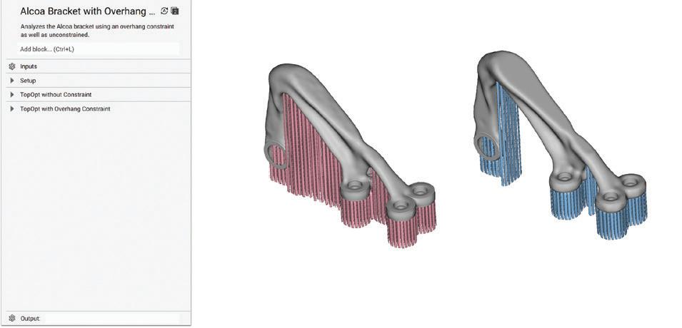
Lattices let designers change a structure’s behavior by controlling its geometry at the enables latticing, texturing, fi lleting, shelling, mesoscale level. Explosion Proof. and other fi eld-driven operations to be previewed in real-time. Complex designs are rebuilt in a few seconds. According to nTopology managers, you can save 10 to 60 seconds every time you change a design parameter. Thus, making 100 such changes a day can save an average of 60 minutes of time per day. Other enhancements include: Lattice generation: Lattices let designers change a structure’s behavior by controlling its geometry at the mesoscale level. Thus, designers can alter material response for specifi c applications. nTopology’s 3rd generation latticing pipeline off ers tools to navigate the mesoscale world. This generation includes a complete set of ordered, stochastic, and TPMS unit cells to control lattice properties at every point in space using simulation results, test data, engineering formulas, and a fi eld-driven design approach. New utilities help designers create custom unit cells and build the basic process blocks that feed generative design workfl ows. Topology optimization: Topology optimization is a core tool of many generative design workfl ows due to its eff ect on lightweighting and structural optimization. nTopology 3.0 uses state-ofthe-art algorithms and unique constraints for Additive Manufacturing. The so ware expands the capabilities of nTopCL and strengthens the integrations


Gearmotors for Class I / Division 1 Hazardous Locations
RATED SPEED TORQUE GEAR RATIOS
24 to 658 rpm 9 to 350 lb-in 5:1 to 300:1
VOLTAGES
230 V or 460 VAC, 3-ph, 60 Hz, BLDC (EC) 12 or 24 VDC
Our new AC inverter-duty and brushless DC gearmotors and motors comply with NEC standards for use in environments where fl ammable gases or vapors are present. Designed to meet IP-66 (TENV) and UL listed, they are ideal for industrial meters, conveyors or pumps in tough environments.
Visit bodine-electric.com for complete specs.
Accuracy Is Nothing Without Repeatability Accuracy Is Nothing Without Repeatability Specify The Position Sensors Specify The Position Sensors With True Precision With True Precision

T/TR family of absolute position sensors feature repeatability to 2µm. They are ideal for machine automation and control applications where precise repeatability and long life are requirements. These sensors offer a proven solution for applications with alignment errors. T/TR position sensors are available with a return spring too for use in auto-retraction systems.

Novotechnik’s T/TR family shares these key specs: • Repeatability to ±0.002 mm • Stroke lengths from 10 to 150 mm • Long life of >100 million movements • Linearity to ±0.075% • Plug or cable connection
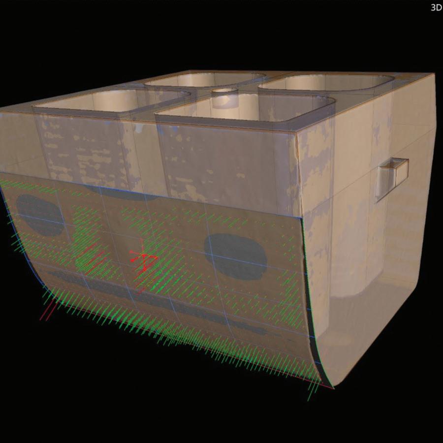
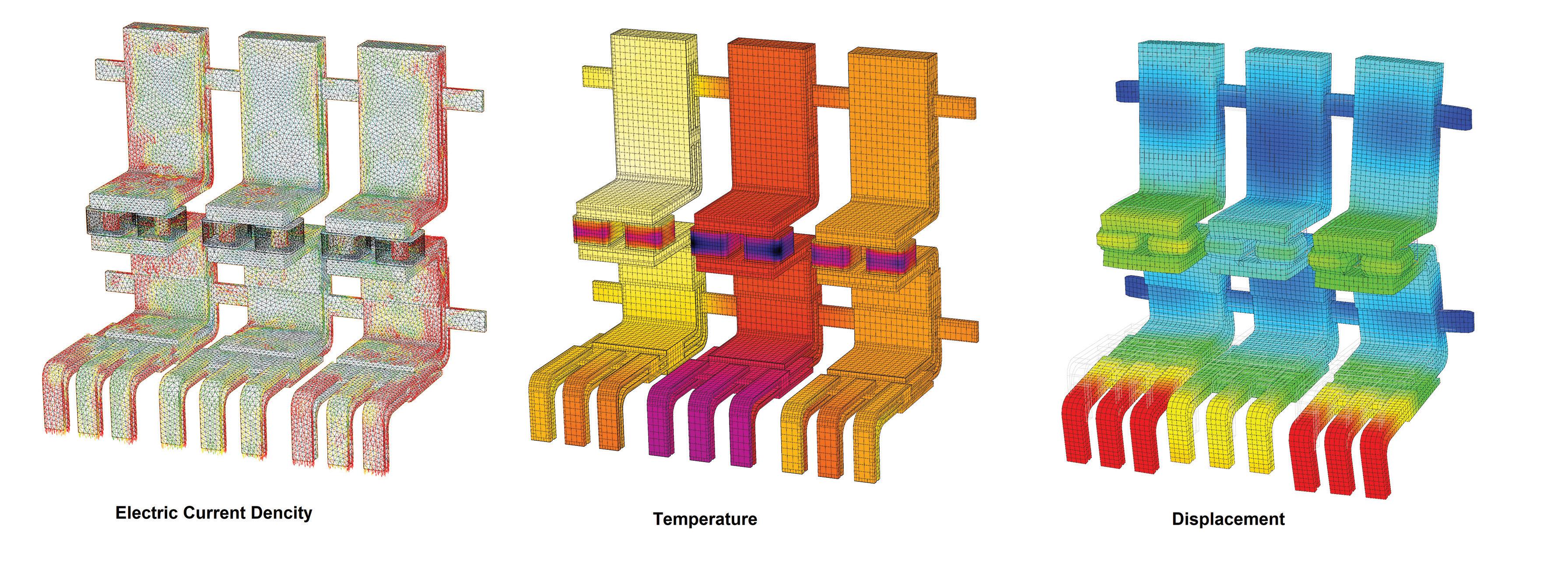
For complete information on T/TR sensors visit www.novotechnik.com/ttr Novotechnik U.S., Inc. 155 Northboro Road • Southborough, MA 01772 Telephone: 508-485-2244 Fax: 508-485-2430 with its Multidisciplinary Design Optimization (MDO) so ware. nTopCL enables users to call generative nTop workfl ows in Python or Matlab scripts. It can run on a desktop, a private server, or the cloud. nTopology 3.0 off ers three ways to simulate. The results can be an input to drive part geometry, or used to perform design analysis, or users can export meshes for verifi cation in external solvers. Built-in simulation tools let users run static, modal, and buckling structural analyses, steady-state, transient, and non-linear thermal simulations, and lattice unit cell homogenization. nTopology is also expanding its simulation preprocessing capabilities. These include new meshing utilities, import and export capabilities for FEA and CFD data in the native format of any solver including ANSYS, Abaqus, or Nastran to streamline the design verifi cation process. DW
nTopology | nTopology.com
WHAT DO YOU THINK?
Connect and discuss this and other engineering design issues with thousands of professionals online
Industrial CT so ware detects and corrects design flaws and manufacturability issues
The latest version of Volume Graphics’ high-end CT data analysis
so ware suite, version 3.5, brings enhanced capabilities to manufacturers looking for better ways to inspect parts and improve designs—however they are made. Particularly in the automotive, aerospace and defense industries, engineers exploring novel materials and manufacturing methods are increasingly turning to CT scanning to achieve a more accurate, non-destructive evaluation of product robustness and performance. Volume Graphics is a leading developer of so ware technology that interprets CT data om scans of almost any material to detect, analyze and visualize minute structural deviations that might aff ect part quality. Version 3.5 provides automated design-geometry adjustment and repair tools that can be used to correct and/or off set issues that stem om the manufacturing process itself. Moldmakers, casting shops, and additive manufacturing providers can use the so ware to detect and visualize material and/or design defects or distortions— and then use included functions to correct their CAD designs, compare values against nominal limits and ensure that fi nal part quality meets applicable industry standards.
Here are some of the highlights in version 3.5 of the data analysis so ware suite (which includes VGSTUDIO MAX, VGSTUDIO, VGMETROLOGY, VGinLINE, and myVGL):
• A reworked manufacturing geometry correction module. This so ware module benefi ts all those who work with some kind of mold, i.e., injection molders or casters. Enhancements in usability, with continuous updating and feedback on quality, give the CAD designer information that can be used to improve manufacturability. Filtering out points that can cause erroneous compensation results, the so ware fi ne-tunes surface fi tting and provides compensations that are within tolerances, enabling the user to immediately see if their design changes are compatible with mold-making.
• Enhanced mesh compensation. For those working in simulation and AM/3D printing, this module provides easier navigation and understanding of the relationships between elements for better interpretation of part warpage, deformation and displacement— and automatically compensates designs to correct for deviations om manufacturing intent. Mesh updating is 10X faster, with improved results when scan and reference objects diff er greatly in size or show other signifi cant deviations. There are a greater number of control points for more granular and accurate results. In the case of lattice structures and other complex geometries, a uniform control-point placement function ensures full analysis of a design. The so ware
Manufacturing Geometry Correction
Module. When compensating a geometry, a new fi lter option in Volume Graphics’ industrial CT so ware version 3.5 allows users to fi nd fi t points that cause inaccurate compensation results.
Enhanced Mesh Compensation.
A new compensation mesh color overlay in Volume Graphics’ industrial CT so ware version 3.5 helps users to clearly visualize, analyze and annotate any displacements in the compensation mesh.

can also shorten the 3D-print-and-test process by automatically running two sequential designcompensation results to move a design for AM closer to nominal before the fi rst print.
• Porosity and inclusion analysis of castings. CT scans of cast parts can be inspected for porosity and compliance with Reference Sheet P 203 of the Federation of German Foundry Industry (BDG). With the help of the BDG P 203 porosity key, users can perform a 3D evaluation of detected volume defi cits both in the complete casting and in eely defi ned sub-areas, such as functional areas with special attributes. The so ware enables inspection of multiple, diff erent regions of interest in a part to see if porosity is within tolerances and whether there are any post-machining issues in the fi nished part. The data om this analysis is then ready for Q-DAS process control.
Capability enhancements support engineering across many industries Other enhancements in version 3.5 strengthen existing functions that support science, R&D, medical device development and other industries in addition to automotive and aerospace & defense. Among these is advanced reporting, which is now more user- iendly and fully integrated with viewing. The nominal/actual comparison module has also been made more user- iendly with easy-to-understand visualization of deviations of scanned objects om their reference data sets. DW New Porosity and Inclusion Analysis of Castings. Usability improvements in the P 203 analysis, in Volume Graphics’ industrial CT so ware version 3.5, include combining the generation and editing of global and freeform porosity keys in one dialog. A new BDG P 203 name fi eld allows users to add a comment for each porosity key.


Congratulates 7

WAGO Corporation provides North America with innovative interconnect, electronic interface, and automation solutions. Extensive engineering resources, a 25,000+ product portfolio, custom manufacturing, and a global network of dedicated professionals ensure WAGO has the resources and expertise to help you get the job done. See our capabilities in action: www.wago.us/capabilities


CFD simulation so ware puts fl ow analysis into the design process early
The latest version of Simcenter FLOEFD so ware, a CAD-
embedded computational fl uid dynamics (CFD) tool, helps users ontload CFD simulation early into the design process to understand the behavior of their concepts. It can reduce the overall simulation time by as much as 75% and it runs seamlessly inside NX so ware, Solid Edge so ware, CATIA V5 and Creo. The latest version includes new functions that let designers take advantage of a seamless working environment, as well as enhancements that extend thermal simulation capabilities and lighting applications. Simcenter FLOEFD includes improvements within process integration, allowing design engineers to implement CFD solutions within their workfl ow without requiring process changes. Simcenter FLOEFD for NX projects and results can be managed in Teamcenter so ware. Integrations with HyperLynx so ware, a suite of analysis and verifi cation so ware for PCB engineers, allow for enhanced thermal analysis and more accurate simulation of printed circuit boards (PCBs) by taking into account joule heating phenomena. The latest version of Simcenter FLOEFD also includes expanded capabilities based on Simcenter MAGNET so ware technology to increase accuracy of thermal simulation by considering electromagnetic phenomena. Direct integration of structural analysis allows CAD-centric users to apply CFD results to perform linear structural stress analysis of complex PCBs accurately. A new interface to Simcenter Nastran so ware allows easy transfer of CFD results for structural analysis in Simcenter 3D so ware. In addition, new enhancements for lighting applications include pulse-width modulation of a light source and the simulation of scattering and photoluminescence of phosphor particles, which are used during the manufacture of LEDs. DW
Siemens Digital Industries So ware www.sw.siemens.com
WHAT DO YOU THINK?
Connect and discuss this and other engineering design issues with thousands of professionals online


