18 minute read
Design Notes
Plastics locked down and laser welded

Jonathan Magee • Managing Director • ACSYS Lasertechnik UK Ltd, Coventry, U.K.


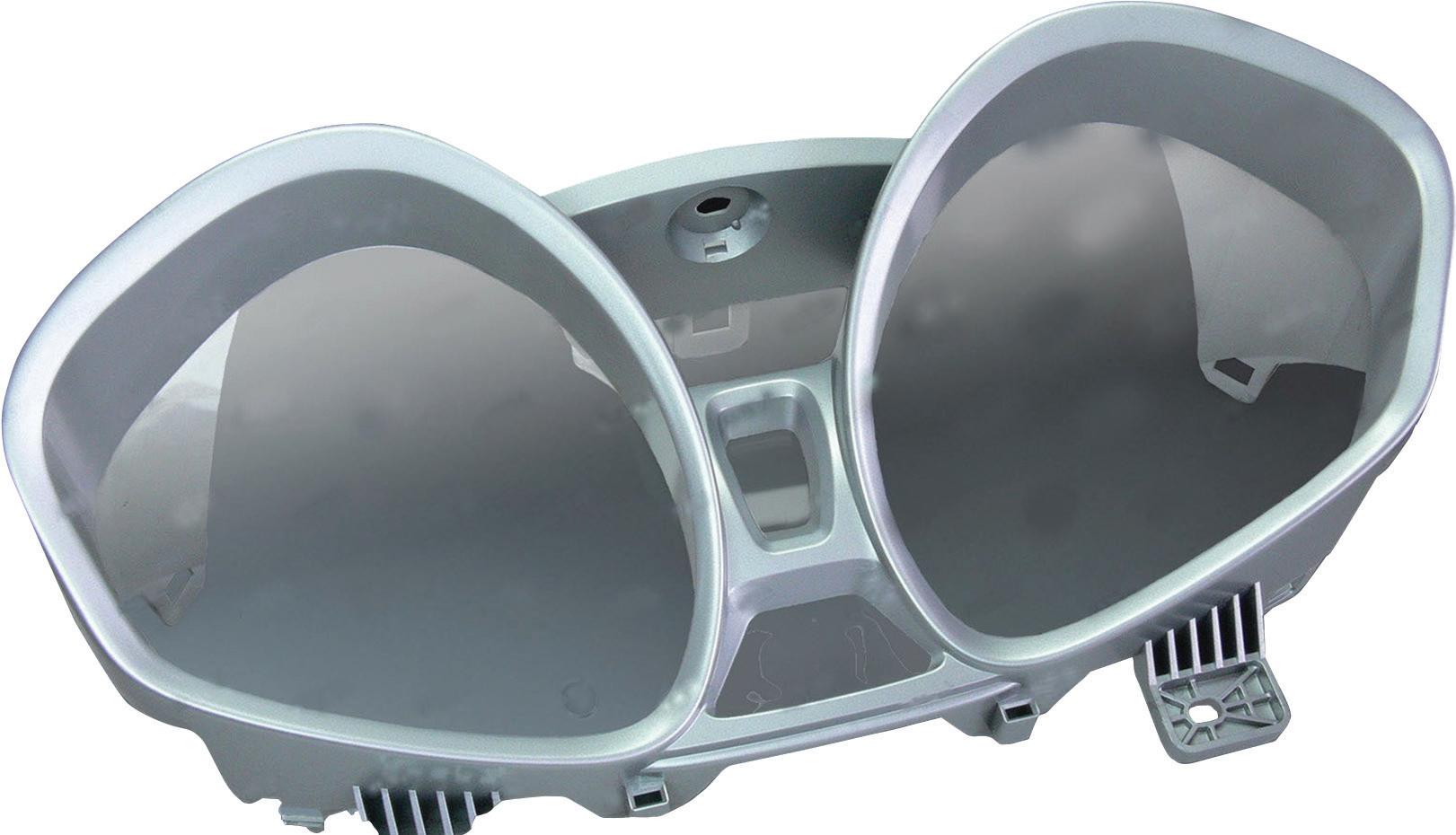
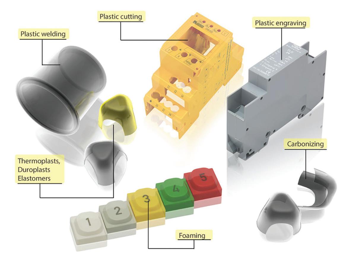
Industrial lasers are used for diverse processing of engineering plastics across many markets. Some examples of the common processes are shown in fi gure 1, including laser marking, cutting, and welding. Well-recognized markets in the fi eld of laser plastics welding include automotive (see fi gure 2), and medical devices.
The rationale for laser plastic welding Laser-based welding has several advantages for plastics versus conventional contact methods. Laser welding is a non-contact process at the point of welding that generally takes place at the interface of overlapped parts, and thus the weld zone is encapsulated. This results in an aesthetically pleasing weld, which is sterile and does not contaminate the surface of the parts being welded. It seems counterintuitive that parts in contact can be welded together, om the top down, without disturbance to their outer surfaces. With conventional plastic welding techniques such as ultrasonic or hot stamping, contact with the outer surfaces of the parts to be welded together is inevitable. Non-contact laser plastic welding works on the principle of partial transmission, refl ection, scattering, and absorption of laser light within the polymer chains being joined. By carefully selecting the plastics and laser’s optical properties, su cient heat is generated at targeted locations to melt and fuse the materials.


Design Considerations for Laser Plastic Welding Plastic products have mechanical, geometrical, thermal, and optical properties among others (refer to fi gure 3). At a fundamental level, the laser weldability of plastic assemblies can broadly be determined by:
1 Are the materials chosen compatible? Compatibility refers to the melting temperatures, chemical, mechanical, geometrical, and optical properties of both plastic parts to be welded.
2 Can the laser beam be transmitted through the top layer material e ciently to reach the joint interface, and can the bottom layer material absorb the laser beam to create heat where it’s needed?
Laser plastic welded

3 Can the parts be held together properly during the welding process, and can the force applied be controlled? Does the geometry of the parts result in a good fi t up between the parts without gaps between them?
4 Can the laser beam be delivered to the parts to eff ectively distribute and control the heat given the geometry?
Thermal and Chemical Compatibility Plastics melt and decompose at much lower temperatures than metals. Typical melting temperatures of engineering plastics are around 250 °C. There are some plastics with much higher melting temperatures, like PEEK, which ranges om 350-400 °C. Close compatibility of melting temperatures will assist mixing of the weld pool and improve mechanical strength on re-solidifi cation. Certain combinations of plastics relatively closely matched on melting temperature are good candidates for plastic welding. The chemical composition of the plastic is also a factor. For example, one cannot weld high-density polyethylene HD-PE to Polypropylene PP, but it is possible to weld lowdensity polyethylene LD-PE to Polyproplyene, even though the polyethylenes are within the same family. Careful consideration must be given to the material combinations.
Matching of Optical Properties Lasers in materials processing generally emit a light beam at one wavelength or a very narrow wavelength bandwidth. Unlike natural light, the laser beam is coherent and focusable. Nearin ared and in ared wavelengths are most widely used in plastics welding om 800nm - 2um, o en by high-powered diode lasers. These wavelengths are longer than wavelengths visible to the human eye, such as green, which is 532nm in the visible spectrum, and red, which is 635nm. Using the 800-2000nm wavelengths the plastics to be welded must exhibit some degree of transmission and absorption in this range. Plastics are, to some degree, semicrystalline structures and have amorphous and crystalline phases. Diff erences in the re active index
Idealized light transmission and absorption in plastic welding.


Design Notes
Correct choice of Plastics - Thermal and Chemical Compatibility

E ective Delivery method for laser beam to part
Successful laser Plastic Weld Matching of Optical of Optical Properties of plastics and laser beam
Su cient Part fi t up, and fi xturing forces along part extremities
between the amorphous and crystalline phases within a plastic cause light scattering and refl ection when a laser beam impinges on them. This can be a benefi t or a hindrance for laser welding, depending on the level of these eff ects. Design combinations of these properties help achieve transmission of the laser beam through the top plastic part and absorption in the lower part, refer to fi gure 4. Sometimes additives are included in the production of the polymers in the masterbatch to make them absorb laser light. At the design stage, engineers should consider whether additives are acceptable in the product. For example, would they pass FDA approval in the case of a medical device plastic? The level of glass fi bers in certain plastics such as Polyamide, PA-66, commonly referred to as Nylon, can aff ect the transmission of light through them, especially at higher levels of glass fi ber concentration where transmission is lower. A equent question regarding plastics is which colors can be welded together? There is no simple answer; many combinations are possible. Even the same color materials such as black to black can be joined with careful design composition. Even though visible light does not transmit colored plastics, this can be the opposite for a single laser wavelength. Su cient part fi t up, and fi xturing forces along part extremities Designers must always ensure that the parts are molded in geometries that lend themselves to laser plastic welding through a good fi t up of the assembly components and joint accessibility. Laser welding is not good at transmitting heat across air gaps, and it is crucial that the components of a joint are in contact. Lap weld confi gurations achieve this. Downward force during the welding process is essential for certain complex parts, especially large ones that are di cult to achieve good fi t up naturally. The clamping force can be generated by servo drives or through the use of pneumatic clamping. There is a collapse force for plastic welding, which governs how much force the hot and melting plastic can withstand before it starts to signifi cantly deform, and how much force is necessary to push the parts together when molten.
Laser Beam Distributes and Controls Heat in an Eff ective Manner There are several methods for laser beam delivery to the workpiece in laser welding. The use of cartesian axes systems where there is a relative movement between a fi xed laser plastic welding head and an XYZR table motion system is one example. These devices may not result in a uniform heating of large parts due to the acceleration required at start and stop points and around changes of direction. However, this method is fl exible as the laser path can be generated through CAD data. The use of high-speed galvo scanning heads allows rapid movement of the laser beam at up to 10m/s. Scanning around a weld seam at very high speed, with su cient power, allows an almost instantaneous heating of the entire welding seam om one end to the other. This reduces the eff ects of simultaneous heating and cooling that cartesian axes systems create. Another less fl exible method is to laser illuminate the parts through a mask. In this case, the mask aperture takes the shape of the required welded seam but must be manufactured each time there is a design change. DW
Design considerations
for laser plastic welding. through a good fi t up of the assembly components and joint accessibility. Laser welding is not
Design Notes
Edited by Mike Santora • Associate Editor
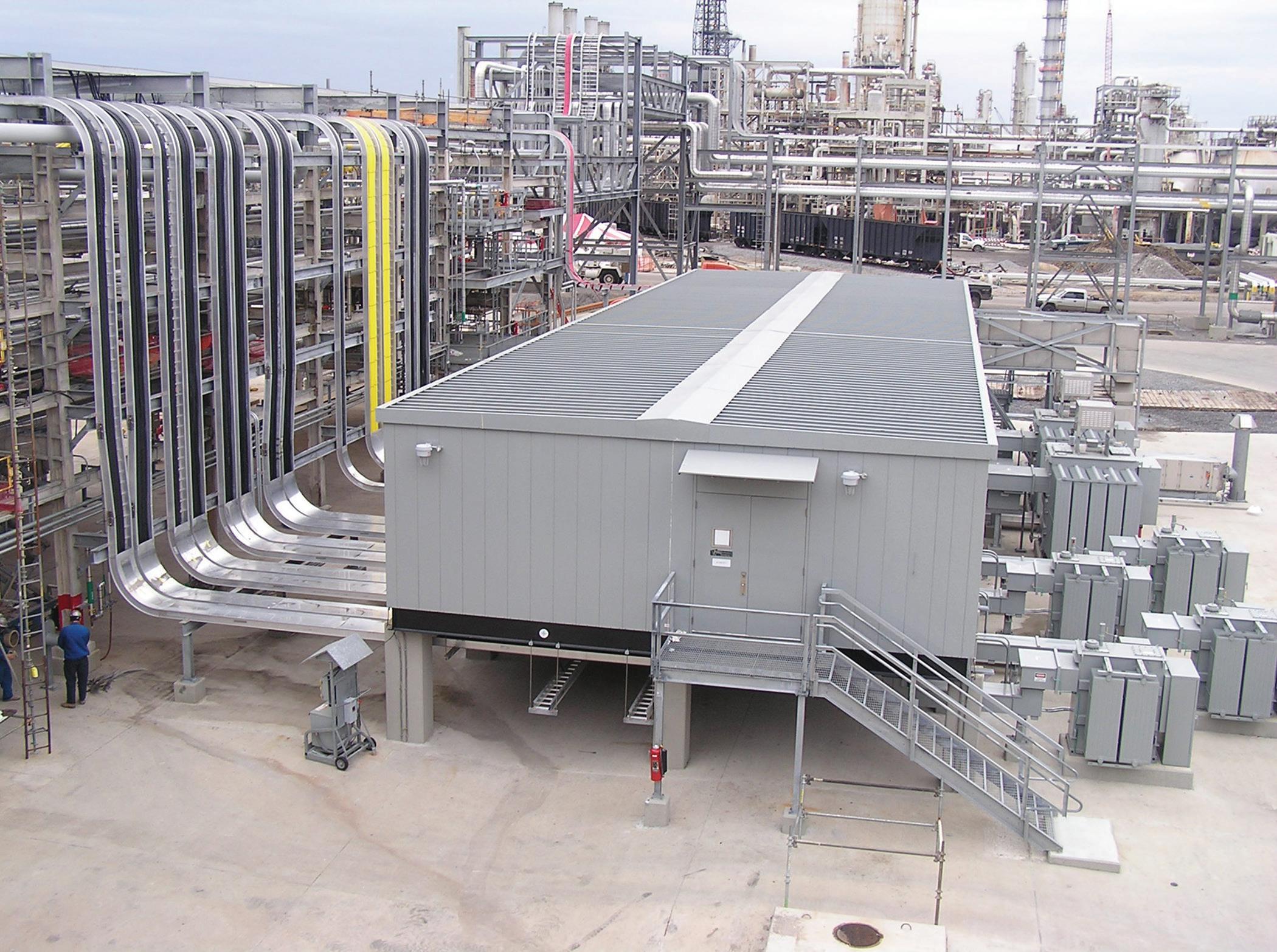
A Powell Power Control Room (PCR).
Powell’s Power Control Rooms (PCR) have improved quality and productivity while lowering costs and reducing labor since their inception in 1968. Used in a variety of markets, om utility substations to oil/gas projects to transportation systems, these PCRs have been transported and installed in all 50 states and over 70 countries. The size of the PCRs varies depending on the fi nal application. “Some are so large they need to be split apart and shipped in sections,” Powell Production Designer Rick Deiss explained. When Powell assembles these larger Power buildings, the sections (or rooms) are physically joined together fi rst. Then the interconnect wiring between each building must be terminated during the manufacturing phase and subsequently “determinated” before the buildings are split apart again so they can be shipped to the fi nal job site. Each section typically includes shipping split boxes for wiring. In the past, when these boxes were shipped, wires would sometimes loosen due to vibration or installation errors. Upon delivery, before connecting the rooms, engineers would need to go into each box, reconnect the wires, and re-tighten the screws that held the wires in place using calibrated torque screwdrivers. This made the process both costly and time-consuming as these specialty tools carry not only a high initial investment but require calibration annually. For mounting connections, Powell had previously used an internally fabricated
Inside Powell’s shipping split wiring compartment: WAGO 832 Series MCS MAXI featuring toolfree, lever-operated termination. It is shown here in a 6-pole wire-to-wire confi guration with mounting adapters for DIN rail or panel mounting.

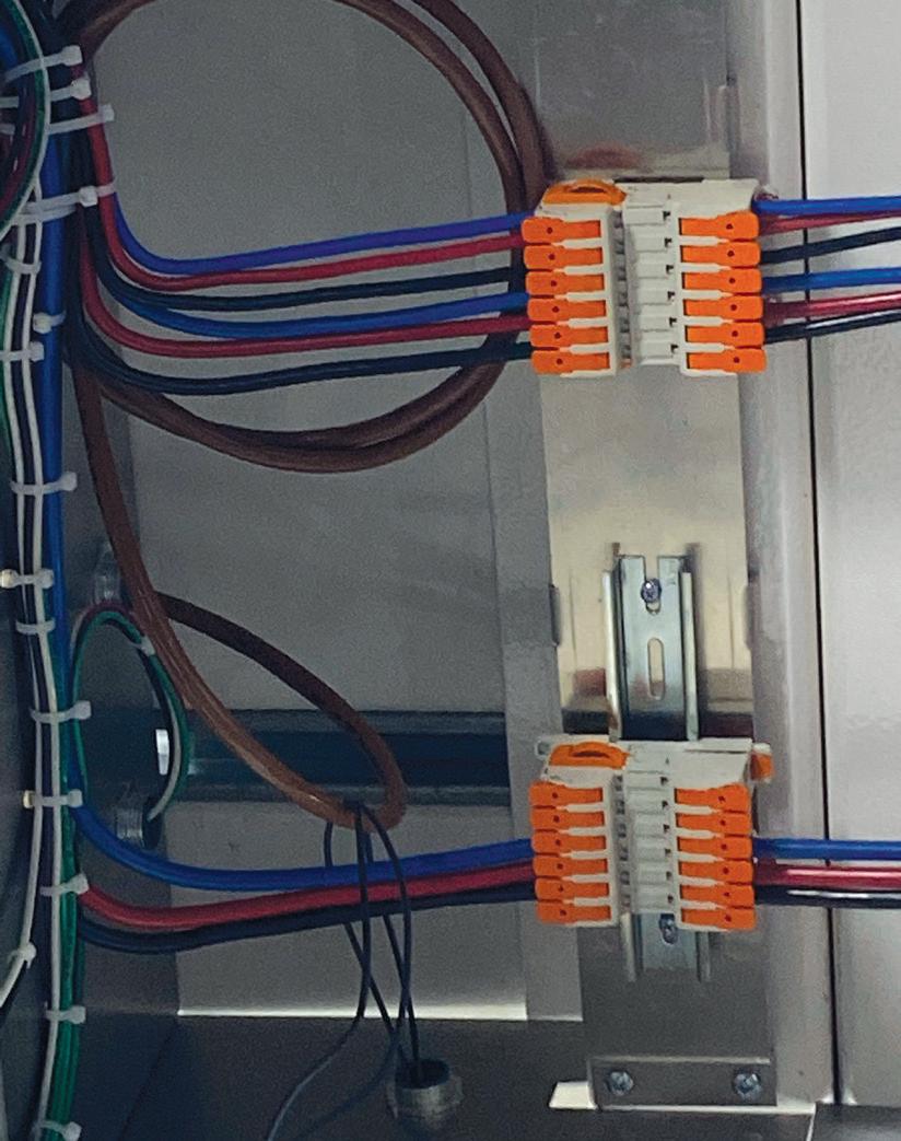
aluminum angle bracket modifi ed with 7 pre-punched square-mounting holes, which would allow a third-party, 2-piece pull-apart terminal block assembly to snap into each square hole. This design, however, was considered labor-intensive and could cause reliability issues, as the connectors would sometimes become dislodged om the mounting bracket. They began to look for ways to improve their design while simultaneously gaining a higher-quality connection. “We needed a terminal block for power connections that could be disconnected by pulling it apart,” Deiss said. In 2016, Ciarah Tapley-Smith of Future Electronics, WAGO’s local distributor in Houston, Texas, and distributor in Houston, Texas, and
WAGO Regional Sales Manager Kevin WAGO Regional Sales Manager Kevin
Stevenson, arranged a visit to Powell Stevenson, arranged a visit to Powell by WAGO’s Innovation In Action Tour by WAGO’s Innovation In Action Tour (IIAT) mobile display. It was then that they (IIAT) mobile display. It was then that they were introduced to CAGE CLAMP design were introduced to CAGE CLAMP design technology. technology. The Powell engineering team assessed The Powell engineering team assessed 831 Series connectors and learned how they could improve connections integrity while reducing production and labor costs. Powell requested samples to see if the connectors could indeed fi t their company’s specifi c application needs. Deiss pointed out that he and his colleagues were also able to visit WAGO’s manufacturing and testing facilities in Minden, Germany, to learn more. “The 831 Series connectors are just what we needed,” stated Deiss, “while touring the WAGO factory in Germany, I saw parts
RELIABLE PRODUCTS TO KEEP YOUR EQUIPMENT HUMMING.


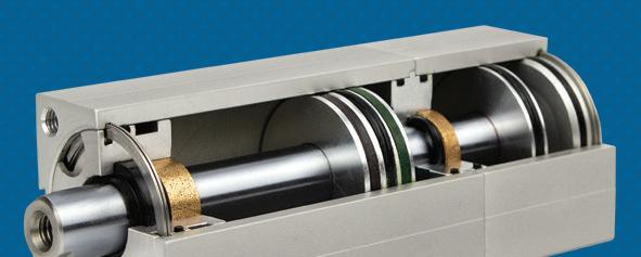

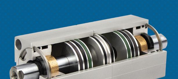

PS Series multi-piston cylinder TW temperature switch
TS Series tandem cylinder NTBT-DL Bluetooth data logging transducer
BS Series back-to-back cylinder
Whether it’s our rugged multi-piston cylinders, our reliable TW temperature switch, our precise NTBT-DL bluetooth-enabled transducer, or any of our other hundreds of switches, cylinders and transducers, when you order from Nason you’ll be getting components designed with today’s most demanding applications in mind. And remember — if you don’t see what you want, give us a call — we’ll build the exact part you need.
Interpower® Outdoor Outlets!

Interpower Outdoor Outlets conform to IEC 60529 and NEMA 250 standards. All are Ingress Protection (IP) rated for “sealing” properties from elements.
IP ratings have two digits. The first digit indicates the degree persons are protected against contact with moving parts, and the degree equipment is protected against the intrusion of solid objects. A “0” rating means no special protection while “6” means dust-tight, the highest rating.
The second digit indicates the degree of protection from moisture. A “0” rating indicates no special protection while “9” indicates the highest protection (water jets).
Interpower’s outdoor outlets are rated IP 65 (protected from dust and jetting water) and NEMA 12/4, indicating they are good for both indoor and outdoor equipment and protected from dirt, dust, and dripping and splashing water.

Toll-Free Phone: (800) 662-2290 E-mail: info@interpower.com
Business Hours:
7 a.m.–6 p.m. Central Time
Design Notes
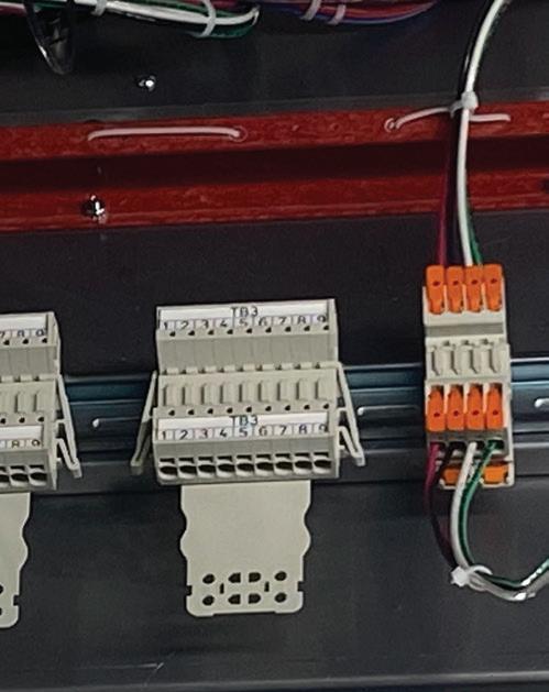
831 Series MCS MAXI in both Push-in CAGE CLAMP (in 9-poles) and lever-operated (in 4-poles) variants with DIN rail mounting adapters. Both provide a safe, convenient, and reliable method of providing pluggable connections inside the shipping split wiring compartments of the PCR.
being manufactured as well as many tests performed on their products.” Powell soon realized that the 831 series would prove to be a critical component in manufacturing their PCRs. “It was evident by their implementation of our original tool-operated, DIN-rail mounted 831 Series that they value our connection technology and form-factor not only as a time and labor savings but also for the improved connection integrity it provides,” says Cory Thiel, WAGO’s PCB Interconnect Product Manager. Powell has since eliminated the cost of lugs and the labor for crimping as well as the need for the pre-fabricated aluminum mounting bracket. With the use of spring pressure connection technology, there are no screws, eliminating loose connections and the need for torqueing. These products have sped up manufacturing, connecting, and disconnecting the shipping splits, ultimately reducing labor costs. Over the last four years, both companies have developed more solutions to help with the production and shipping of Powell’s Power Control Rooms. So what may be on the horizon? A new version of the 831 series with tool- ee lever actuation is currently in production. Powell is also looking at using new 832 Series connectors to replace additional competitive devices and some old connections requiring larger wire connectors. “Powell is looking to implement more of our products in their design and are very excited to hear that we will soon have the 832 Series connectors coming out later this year with a DIN Rail-mount capability,” Stevenson says, “which will allow them to use our CAGE CLAMP technology on larger wiring circuits ranging up to 4 AWG.” Deiss also expressed his enthusiasm for the future, “I am very excited about the 832 Terminal Blocks. These have larger ampacity ratings, so we will pull apart connections for up to #4 gauge wire. Currently wiring larger than #8 requires lugs, screw terminations, and torqueing.” With the help of these products, Powell will continue to work on speeding up and simpli ing the wiring process. DW
WAGO wago.com
WHAT DO YOU THINK?
Connect and discuss this and other engineering design issues with thousands of professionals online
Design Notes
Metrology for micro molding — a case study
Edited by Mike Santora • Associate Editor

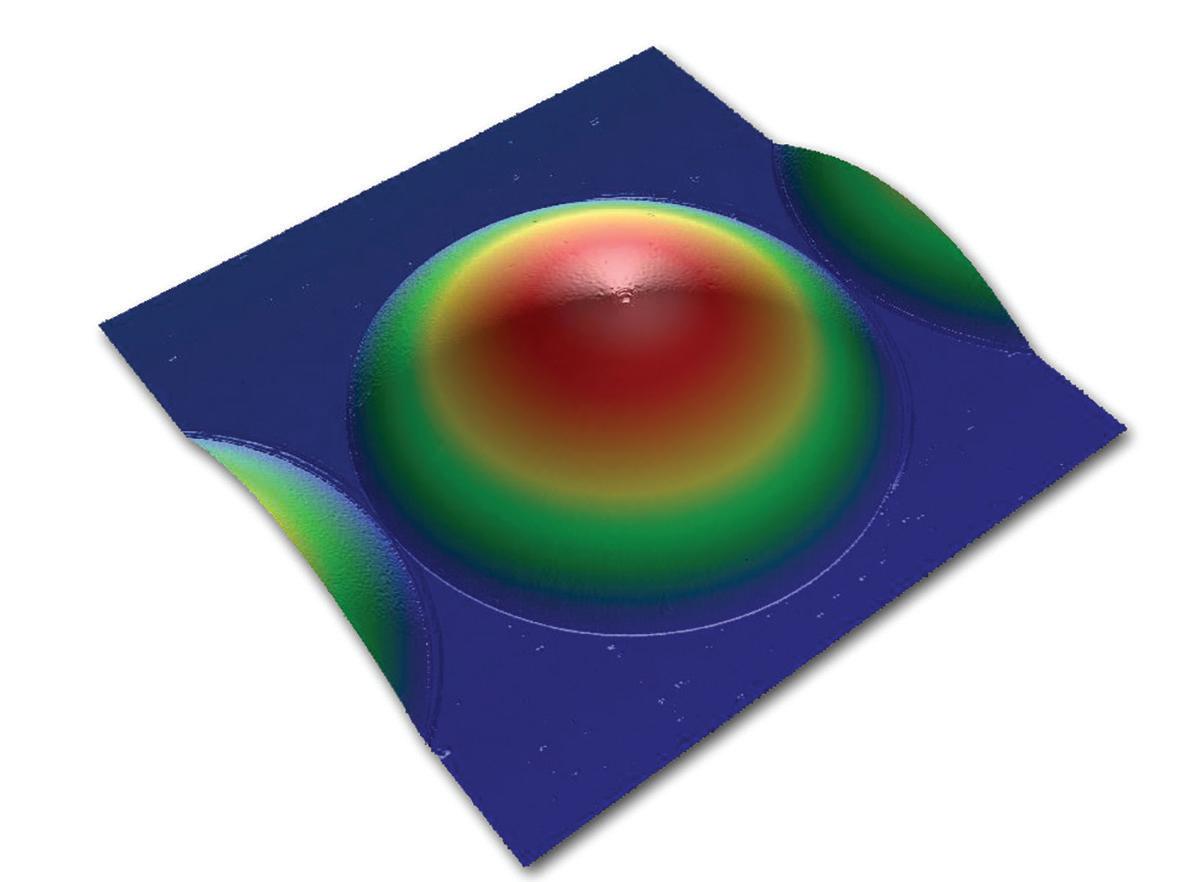
Inspection of a microlens (a single lens that is part of a molded lens array). This kind of data is used to fi nd defects and assess overall shape of the molded part. This ensures design accuracy.
Accumold operates in an environment where part dimensions are sometimes minute, tolerances are always exacting, geometric complexity can be demanding, and zero failure rates and repeatability are paramount. The key to reaching sub-micron tolerances is risk mitigation, as each step in the product development process can potentially introduce tolerance stack-up. Control requires that Accumold is vertically integrated, with tooling, molding, validation, and automated assembly all under one roof, and each “department” collaborating to ensure optimal outcomes. Validation is a crucial, which is why Accumold partnered with non-contact optical metrology specialist, ZYGO, to manage some of its more demanding measurement and some of its more demanding measurement and validation work. Nowhere is the well-worn validation work. Nowhere is the well-worn phrase “if you cannot measure it, you phrase “if you cannot measure it, you The diamond turned surface cannot make it” more relevant than in the cannot make it” more relevant than in the
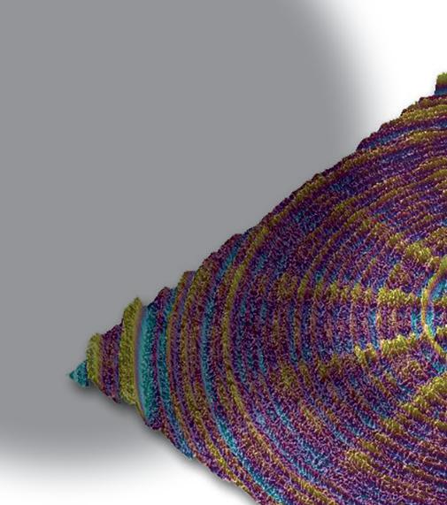
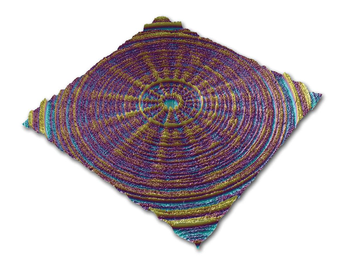
shows the texture on a piece of injection molding tooling for an optical
surface. Understanding and controlling the texture on the mold tooling is important as it will transfer directly into the fi nished part.

world of micro molding. Here, parts are o en used in safetycritical applications and can be as small as a grain of sand. Accumold’s metrology capability is critical during micromolding processes — om initial experimental design runs and stress tests to prototype and production qualifi cations runs. With measurement taking this central role, metrology moves om being a necessary evil to an enabling technology. Accumold’s metrologists have been successful in helping customers improve their design, re-dimension parts, and better use Geometric Dimensioning & Tolerancing (GD&T) so that the part is easier to mold, easier to measure, and performs better for the end-user. O en in micro-molding scenarios, metrology and validation-related issues can be challenging, with part size, part fi xturing, print tolerances, and surface roughness introducing complexities. Of these, part size is the most critical challenge. Micro-molded parts can be dimensioned in microns, with features that only become visible under 10x (or greater) magnifi cation. With such small part sizes, noncontact metrology is the best solution. It is essential to determine how to fi xture the part being inspected so repeatable and reproducible measurements are achieved. Accumold designs and manufactures steel
or 3D plastic custom fi xtures designed to hold parts in various orientations to ensure they can measure all the features in either automated or manual measurement processes. Another challenge for these components is surface roughness. Due to the small size and essential fi nish requirements, slight variations can have more dramatic eff ects on the fi nal product than might be observed with a larger component. Non-contact metrology tools are vital for such applications, as tactile tools can compromise surface integrity. Metrology instruments are constantly evolving, and it is essential to assess new technology continuall.y. Accumold uses various advanced metrology technology, including automated vision inspection (AVI), robotic handling, and non-contact optical surface metrology, such as the coherence scanning interferometer equipment om ZYGO to measure micro features and surface roughness. Industry perceptions of optical metrology systems have changed in recent years, and its uptake is growing year to year. There are obvious reasons for this: its ability to measure without damaging surfaces or features on sometimes delicate components. However, optical metrology also stimulates the move to greater manufacturing automation due to its speed compared to contact systems. It can also quickly undertake full-fi eld measurement rather than focusing on specifi c part features one at a time. Accumold has used ZYGO optical profi lers for many years, starting with the NewView 7300 and later adding the next generation NewView 8300 to the fl eet. The main reason for selecting ZYGO was to accurately measure parts made om high temperature and clear resins used to mold lenses. One of the best ways to derive maximum value om metrology is to work more as partners and collaborators to solve a challenging problem. The fi rst collaboration’s optical profi ler was the NewView 7300. Both company’s engineering teams devised a customized analysis routine for the micro-molded lenses that were being made. As technology evolved, the two companies continued to work together to solve metrology issues both on the original tool and on the NewView 8300 and its latest so ware platform. Instead of simply purchasing a tool, ZYGO and Accumold have maintained a dialogue to ensure ZYGO’s product and capability roadmap refl ects Accumold’s metrology needs — continually providing value across their entire organization. Accumold thinks that working collaboratively with metrology suppliers is the future and will ensure that technology evolves with market and customer needs. DW

Zygo www.zygo.com
SICK OF SNAP RINGS?
We were too.
That’s why we are the only manufacturer of Spirolox®.
• Easy and Quick Install/Removal • Interchangeable with Snap Rings • • Large Selection from Stock Large Selection from Stock • • Easy to Customize Easy to Customize
Spiral Retaining Rings
