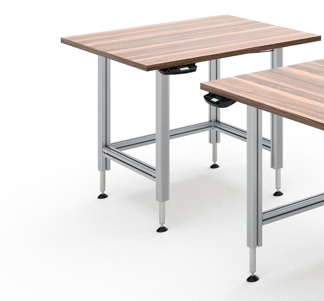
Back injuries are one of the most common injuries in the workplace and are often caused by carrying heavy loads, twisting while holding something, or working in one posture or an odd position for long periods. These injuries can be limited greatly with the use of table lifting systems.
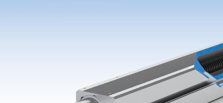
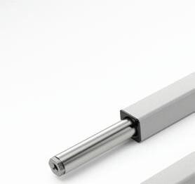
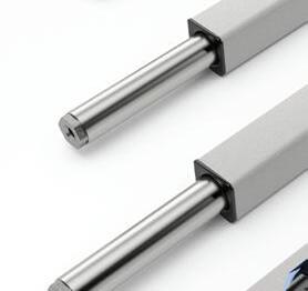
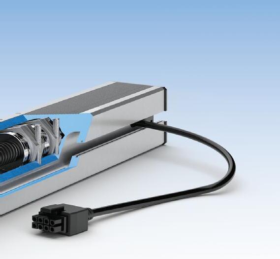
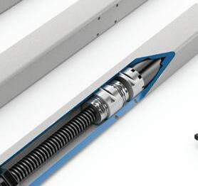
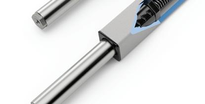
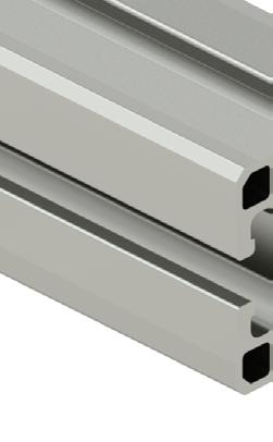
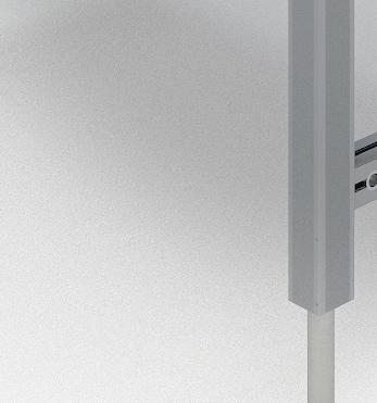
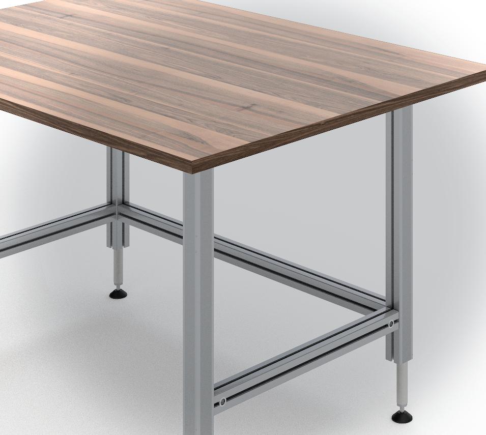
The Ergoswiss SQ series lifting system uses electrically-driven columns (no hydraulic mess and no manual hand cranks) that allow the operator to reposition the height of the worktable, conveyor, etc. to meet their specific requirements. Each column is capable of lifting 330lbs with available lifting heights of 12 or 16 inches.
Use 4 columns per controller for up to 1,320 lbs of lifting capacity!
ERGOSWISS SQ SERIES
Columns starting at $500 / Kits starting at $1,955.00 Ergoswiss lifting columns provide an affordable solution for adding ergonomic height adjustability to operator controlled equipment.
• Columns sold individually or in two convenient kits with controller and 4 columns included
• Controller can operate up to four lifting columns and can be synced with an additional controller for up to another 4 columns (8 total)
• Easy-to-use Up/Down buttons and memory settings
• Tilt sensor for added safety that will stop operation if it senses a tilt of more than 2.5 degrees
SUREFRAME APPROVED
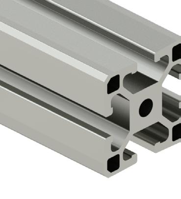
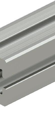
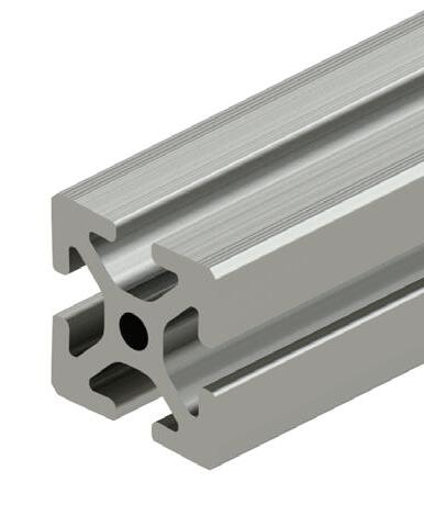
Compatible cut-to-length rails starting at $0.53/in Ergoswiss lifting columns work well with SureFrame 15 series and 40 series T-slotted rails. Use these rails and Ergoswiss lifting columns to build adjustable tables, workstations, or any structure your system requires.
Kits
Easier access to more of our content
EVERY OTHER MONTH, readers of Fluid Power World have access to our beautiful print and digital editions, where we share a selection of the best fundamentals content, technology news, case studies, and technical articles that cover the gamut of hydraulics and pneumatics system design. But we only have so much space in each print edition that publishes February, April, June, August, October and December (which is now our annual Fluid Power Handbook — this issue features all new articles on design and selection of fluid power technologies).
Regular readers know that the dozen or so articles in print are just the tip of the iceberg of all the content we write to help educate the industry on all things fluid power. We have five websites and related newsletters dedicated to providing the best content in the fluid power space — fluidpowerworld. com, mobilehydraulictips.com, hoseassemblytips.com, pneumatictips.com, and sealingandcontaminationtips.com. We always have much more content than the space in our print edition allows.
This is why starting in March 2025, we are launching new digital-only editions of Fluid Power World. These will be sent to readers in March, May, July, September, and November 2025, and will feature more of the informative engineering basics, tutorials, troubleshooting tips, and more that you have come to expect and love from our crack editorial team. Another way to look at it is that we’re going monthly, from a “magazine” perspective.
We’ll have opportunities to share new departments as well. While our Fundamentals, Component Focus, Energy Efficiency, and other regular features will still be included on occasion, we’ll have a chance to introduce readers to some all-new content, such as our exciting Fluid Power Profiles, where we will feature a professional working in the industry, learn how they got started, what they do, and why they love the fluid power industry. You’ll also have access to other columns we don’t publish as regularly, such as Association Watch, to learn all that our industry-leading organizations are doing. There will also be an expanded Product World, and so much more.
Make sure you are subscribed to our
digital editions to ensure that you receive these new issues starting next year. And please don’t hesitate to contact me if there’s something you would like to see us cover in future issues of Fluid Power World. As always, thank you for reading!
Mary C. Gannon • Editor-in-Chief mgannon@wtwhmedia.com linkedin.com/in/marygannonramsak
STRONG
Compact safety rotary encoders for position and speed measurement
Dynamically compensated inclination sensors for precise angle measurement
Position sensors for stroke measurement in hydraulic cylinders
Precise position with SIKO
Products Inc. – www.siko-global.com
EDITORIAL
VP, Editorial Director Paul J. Heney pheney@wtwhmedia.com @wtwh_paulheney
Editor-in-Chief Mary Gannon mgannon@wtwhmedia.com @dw_marygannon
Associate Editor Heather Hall hhall@wtwhmedia.com @wtwh_heathhall
Contributing Editor Josh Cosford @FluidPowerTips
Contributing Editor Carl Dyke @carlindustry
Contributing Writer Robert Sheaf rjsheaf@cfc-solar.com
PRINT
VP, Creative Services Matthew Claney mclaney@wtwhmedia.com @wtwh_designer Art Director Erica Naftolowitz enaftolowitz@wtwhmedia.com Director, Audience Development Bruce Sprague bsprague@wtwhmedia.com
MARKETING VP, Operations Virginia Goulding vgoulding@wtwhmedia.com @wtwh_virginia
Digital Marketing Manager Taylor Meade tmeade@wtwhmedia.com @wtwh_taylor
LEADERSHIP CEO, Co-Founder Scott McCafferty smccafferty@wtwhmedia.com @SMMcCafferty SALES Ryan Ashdown 216-316-6691 rashdown@wtwhmedia.com Jami Brownlee 224.760.1055 jbrownlee@wtwhmedia.com
FLUID POWER WORLD does not pass judgment on subjects of controversy nor enter into dispute with or between any individuals or organizations. FLUID POWER WORLD is also an independent forum for the expression of opinions relevant to industry issues. Letters to the editor and by-lined articles express the views of the author and not necessarily of the publisher or the publication. Every effort is made to provide accurate information; however, publisher assumes no responsibility for accuracy of submitted advertising and editorial information. Non-commissioned articles and news releases cannot be acknowledged. Unsolicited materials cannot be returned nor will this organization assume responsibility for their care.
WTWH Media, LLC; 1111 Superior Ave., Suite 2600, Cleveland, Ohio 44114. Periodicals postage paid at Cleveland, OH & additional mailing offices.
POSTMASTER: Send address changes to: Fluid Power World, 1111 Superior Ave., Suite 2600, Cleveland, OH 44114
SOMETIMES, WE FLUID POWER PROFESSIONALS can’t see the forest for the trees. We take for granted the first-day education we experienced in college or university that provided the foundation for everything in this fluid power forest we thrive within. Every one of you didn't know the difference between pressure drop and back pressure before you were taught, and to be honest, there are less than well-trained fluid power professionals who still do not.
If you’re reading this, you’re either a fluid power professional or a neophyte looking to become one. Any foundation starts with a solid base, and many subjects such as geometry, pressure drop and symbology fill the bottom of the fluid power knowledge pyramid. A critical buttress in the foundation of knowledge is Pascal’s Law.
I try to write using accessible and colloquial verbiage, except when I use pretentious phrases such as colloquial verbiage Nevertheless, Pascal's Law is a beautiful discovery that never fails to illicit wows from those reading about it in textbooks or pushing interconnected syringes to operate a fluid power challenge device.
The origins of fluid power
Pascal’s Law explains the very nature of the hydrostatic force that holds mass and moves loads. Named after the French mathematician and physicist Blaise Pascal, the law states that "pressure applied to an enclosed
What is Pascal’s Law?
fluid is transmitted undiminished to all areas of the fluid and at perpendicular vectors to the walls of its container." Okay, maybe that description is more advanced than elementary, so let's break it down.
Imagine you are seated on a cork that is plugging a giant, water-filled flask (Figure 1 –yep, that’s you). That cork presses down on the water with a force intensity factored by both the surface area of the cork and your slender mass (or swole mass – whatever you're going for). Because this is an elementary discussion, we'll also discuss the pressure triangle (Figure 2).
Using the triangle, you can arrive at Force, Area or Pressure by following the mathematical direction of the other two variables. For example, multiply Pressure by Area if you want to calculate Force. If you want to determine Pressure, divide Force by Area. For example, if we apply 3,000 psi by an area of 12.56 in.2, we arrive at 37,680 lb of force.
Returning to your precarious perch atop the giant water flask, let's assume your body weight is a lean 200 lb from your years of
CrossFit. Your chair/piston/cork happens to be constructed from tungsten, weighing 99,800 pounds and machined to 20 in. diameter at the base. You'll notice I said diameter, yet the FPA Triangle requires area.
The area of importance is the bottom surface of the chair/piston/cork, for which we use the trusty formula of πr2 to calculate how many square inches make up the circle. Expanded, the formula is Pi x (radius squared), so we must first calculate the radius. The radius of a circle is exactly half
its diameter, so we're talking about 10 in. Pi is a non-terminating decimal rounded frequently to 3.14. Putting it together, we write it out as A = 3.14 x 102 = 314 in.2 (remember to square the radius as the first step).
Back to the FPA Triangle, we're calculating pressure, so we must divide the force by area. The force is the combined 100,000 lb from you and your chair/piston/cork, and the area is 314 in.2 Thus, 100,000/314 = 318.5 pound per square inch (psi). In hydraulic terms, 319 psi is relatively low, but stop to think about pressure, and if it helps, get a ruler and draw a 1-in. by 1-in. square on a piece of paper. That one square has more than your body weight pressing down upon it, and now expand your imagination to include 314 of those squares exerting the same force.
The power of the cylinder
I'll remind you again of Pascal's law: "Pressure applied to an enclosed fluid is trans-
BLAISE PASCAL
FIGURE 1
FIGURE 2
mitted undiminished to all areas of the fluid and at perpendicular vectors to the walls of its container.” Our flask is indeed enclosed, and pressure is applied by you and your chair/piston/cork. For the purposes of this discussion, the pressure exists equally at every spot in that flask, although if the flask were ocean-deep, its water's mass would result in higher pressure at the bottom. But let's ignore that for now.
What's often misunderstood is how the force only acts at right angles to the pressure surface. The pressure your chair/piston/ cork applies is straight down, and the opposing pressure vector is straight up. Regarding our circular flask, the pressure acts only at right angle radii to each infinitely small angle.
The primary reason circular shapes are so strong under pressure is the diffuse direction force acts upon its walls. Conversely, a cube has six flat surfaces for which pressure is unified against each surface. Even just a few psi inside a sealed reservoir can turn it into a barrel shape. However, nearly every shape used in fluid power is cylindrical — hoses, ports, spools, cylinder pistons, pump pistons, etc.
There is little practical purpose in perching on the flask, so expect to ask passersby if they dig your tungsten chair/piston/cork. So long as the outside diameter of the tungsten piston area remains sealed with the inside diameter of the flask stem, you’ll effectively float as the mass above is equalized by the
pressure below.
The real fun begins when you open the flask to other shapes. Imagine you now take two containers joined by a channel. You sit atop your chair/piston/cork, and your combined 100,000 lb still requires 318.5 psi to keep you from sinking because the system is no longer sealed. The channel ends at the other side with a similar, but smaller, cylinder with a small weight atop its chair/piston/ cork (Figure 3).
Intuitively, you would expect there is no way the smaller weight on the smaller chair/ piston/cork could do anything but shoot skyward as your combined weight drops you like a rock into your open cylinder. You might be surprised to learn you would actually rise higher as the small weight drops down. Let’s do some quick math to explain.
The smaller chair/piston/cork has a diameter of 10 in., and because we’re using exponents in our math, the surface area is much less than half the diameter. Using the same πr² that was previously discussed, we calculate the area as only 78.5 in.² We only need to use the FPA Triangle to calculate the force: 318.5 psi x 78.5 in.² = 25,002 lb.
So how does something that weighs 25,000 lb move something that weighs 100,000 lb? Well, that's the magic of Pascal's Law! You can't get something for nothing, so what gives? The caveat is that the smaller weight has to move four units for every single unit of
movement for you and the chair/piston/cork. For example, if the small weight moves four inches, you'll only lift one inch. If you're clever and paid attention in science class, then you know this not unlike a lever ratio.
In Figure 3, we show the math required to calculate these ratios. We know that P1 equals P2 — because of Pascal's Law. The quotient of F1/A1 equals the quotient of F2/ A2, or in simpler words, the equation works. If we bump the weight on the smaller chair/ piston/cork to 26,000 lb, the math increases the pressure to 331 psi. Since your weight and the perch are “only” 100,000 lb, the 331 psi now working on the 314 in.² of your chair/piston/cork equates to 104,000 lb, easily raising you higher.
Pascal’s Law and hydraulics
If you allow me to expand your mind briefly, let's zoom out and look at how these force ratio concepts apply to hydraulics. The smaller you make the piston for any given force input, the higher pressure it creates. The trade-off is that you need to move the smaller piston a farther distance equal to essentially the area advanced by the larger piston. Moving an area through distance creates volume; we can also look at this from that perspective.
In hydraulics, we prefer to work more quickly than can be achieved through the limited scale of Figure 3. Instead of pistons/ chairs/corks, we use pumps, and quite small ones, relatively. Instead of area, we describe a pump by how much volume it creates in a single rotation, and then we spin those pumps at thousands of revolutions per minute. The surface area of any given vane, piston or gear on these pumps is a fraction of a square inch, showing you how something small can lift something big, but it’s actually the whole point.
Blaise Pascal made a discovery so monumental that his original tests and experiments must have triggered accusations of witchcraft. Without his discoveries, my life, your life and the life of every future fluid power professional may look vastly different. If you know a young fan of STEM, forward this article and allow them to take their first step into the magical forest we call fluid power. FPW
How electrified controls simplify hydraulic machines
HYDRAULICS IS A VENERABLE TECHNOLOGY as mature as any competing force transfer system outside of straight mechanical conveyance. Most recent hydraulic advancements aren’t from any fundamental changes in the pump, valves and actuators used in hydraulic systems but rather from the implementation of increasingly advanced electronic technology.
Early fluid power technology
The early days of fluid power technology were strictly limited to manual operation of valves with limited versatility. Joseph Bramah’s first hydraulic press was as simple a circuit imaginable. It was equipped with a single hand pump aided by two check valves, as is typical of current technology. It extended the cylinder upwards for printing and seed oil processes.
This single-acting press design used a ball screw as the return valve, which, when screwed open, would allow the press to lower. As circuits became more complex,
bespoke solutions such as cast iron housings with machined internals and custom spools rose in popularity. With no industry standards, machine builders created unique solutions that suited their application only, but such designs were bulky, complex and expensive.
In the late 1800s, the Industrial Revolution changed the nature of manufacturing, and companies began using machines to make machines. The flurry of creative ideas and subsequent patents led to an explosion of designs as engineers and entrepreneurs searched for the "better mousetrap." When the dust settled, the spool valve replaced ball and gate valves, especially after the switch to mineral oil from water in the early 1900s. Mineral oil provided the stable viscosity and lubrication properties a spool valve needs to work effectively, but these valves were still manually operated.
Any hydraulic circuit was either plumbed with pipe or machined into casting, and despite this, circuits were increasingly complex. Any type of automation required
the installation of separately installed and plumbed cam, plunger or roller valves in addition to various pressure valves, which, of course, had to be separately plumbed using pipe if they weren’t installed into the castings mentioned earlier.
The downside to these old technologies was not just in the complexity of design and manufacture but also in the lack of ergonomic consideration for their operation. Any lever that operated a function couldn’t always be located in a single, convenient location, so functions would have required inconvenient personnel movement to activate subsequent functions.
For mobile machinery especially, a lack of convenient control location made work difficult until spool valves with inline bodies allowed designers to locate levers within reach of a single operator. Clever engineering alongside the switch to hose and tube plumbing provided more versatile control systems that could be installed in a single workstation. Although centralized plumbing provided a leap in ergonomics, any hose or fitting leak resulted in a bad day at the office.
Increasing flow rates forced changed designs
Searching for ways to move valves outside the cab became a priority when flow rates increased alongside machine size. We could simply no longer pack the cab, Figure 1, with control valves grown to use 1 in. NPT ports and larger. The implementation of cableoperated valves led the way to hydraulic pilot control, as flow forces at high pressure and flow made operation difficult with strictly mechanical control.
Still, pilot control of directional valves added a level of complexity above and beyond what were already increasingly complex hydraulic systems. All the advanced features of modern excavators, for example,
FIGURE 1
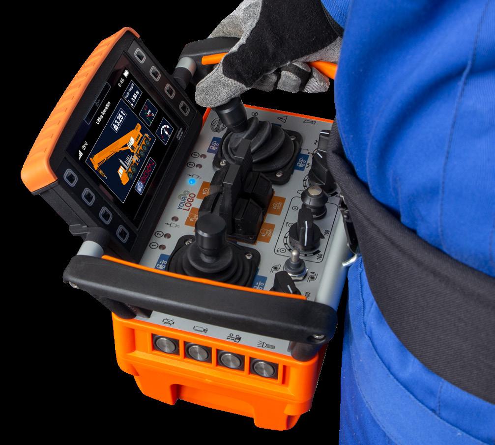
You THINK it.
Controllers | Displays | Keypads |
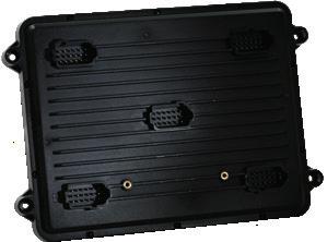
Intelligent Vehicle Controls
HED builds rugged and versatile vehicle controls that are made to perform in harsh worksite environments - helping OEMs design system controls that can assist with quality, efficiency and safety goals.
Controllers
• J1939 CAN or CANopen systems
• Software configurable I/O
• Modules from 8 - 69 I/O
• Multiple CAN ports
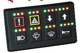
Keypads
• Tri-color indicators and backlights
• Customizable icon sets
• J1939 CAN or CANopen
• Finger key locator
Displays
• 5 to 15 inches
• High-brightness with ultra-wide viewing angles
• Crank, Qt, CODESYS or BSP
• PCAP - use with gloved hands
Telematics
• Remote diagnostics & programming
• 4G LTE, Wi-Fi, cellular, GPS
• Integrated security
• Data logging
such as load sensing and horsepower control, are now operated with complicated directional valve packages. As ingenious as many of these hydraulic controls were, there had to be a better way to maintain or improve performance while reducing complexity. Enter electrification.
Early electronic controls
The first electrically operated valves were created in 1905 by ASCO (the very same “Red Hat” company now merged with Numatics). These were process valves meant for everyday fluids, like water, but the concept of electrically operated valves was proven, and other manufacturers followed suit.
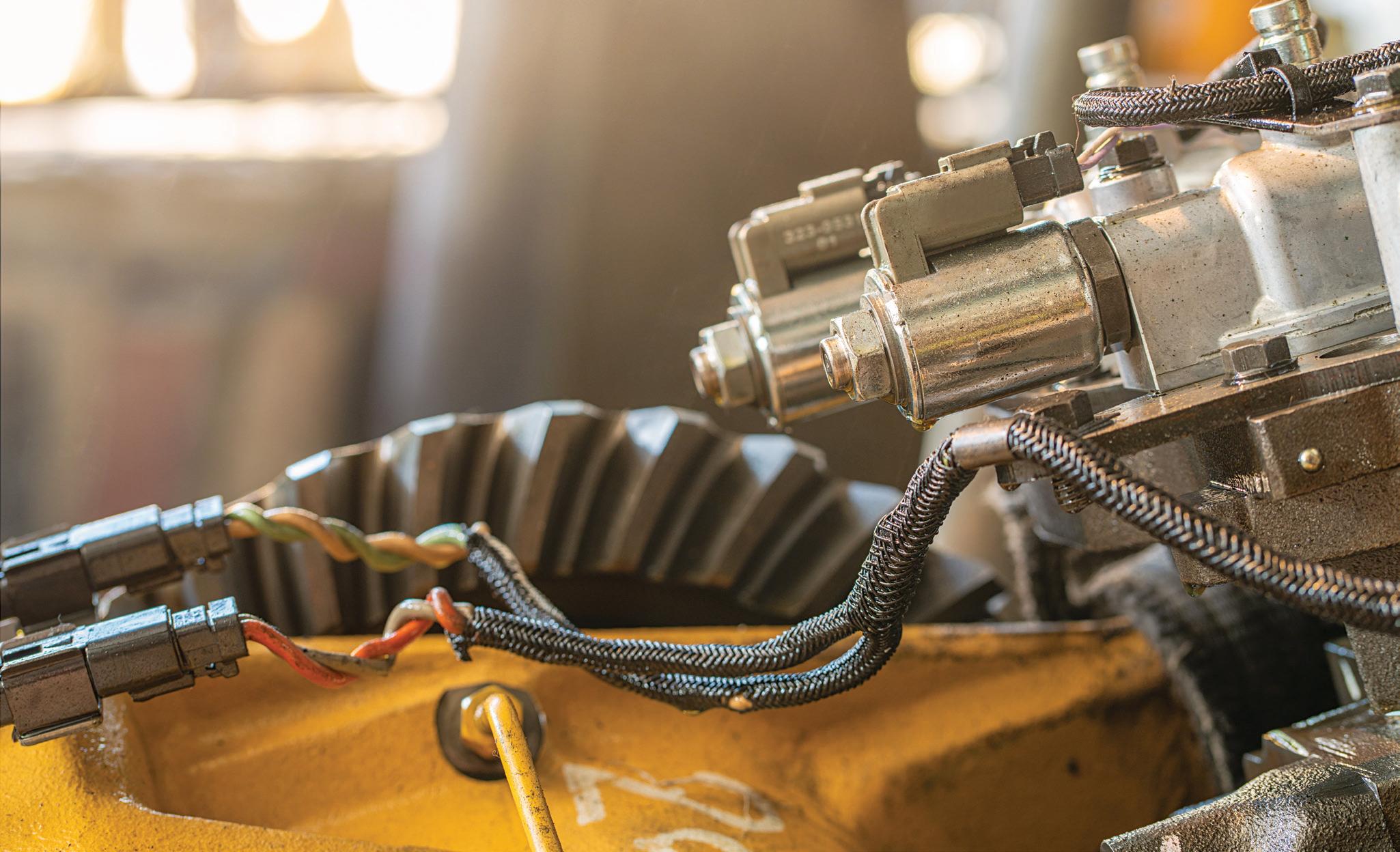
Solenoid-operated valves, Figure 2, became popular in hydraulics over the postDepression era, although they didn’t pro-
liferate widely until the Second World War. Industrial manufacturing perfectly suited the switch to electrification, as the valves operated remotely were better suited to be installed near the actuators or power unit. Mobile hydraulics took longer to adopt the switch to electronic control since many functions required proportional control, which, at the time, was more expensive than simply using lever valves that were already easy to modulate by hand.
Once the widespread switch to electrified controls through the second half of the 20th century occurred, the naysayers and late adopters had little defense over leveractuated valves. The usual complaints about what to do during blackouts or electrical failures became few and far between, and now electrified controls are the norm across
many industries using fluid power, and for good reason.
Electrified controls provide more precise control over hydraulic actuators, leading to improved positioning, force, and speed accuracy, especially when combined intelligently with position and pressure feedback. This precision is crucial in applications requiring tight tolerances or accurate velocity and force. Simple PLCs with closed-loop control of such actuators provide the simplest method to achieve accurate force and velocity.
Additionally, electrified controls allow for easier machine automation integration, enabling complex operations sequences, feedback loops, and advanced control strategies like proportional-integral-derivative (pid) control. Machines can be programmed to perform tasks autonomously with minimal human intervention. Previous machine automation tactics in fluid power required myriad mechanical valves, miles of hydraulic plumbing, and sequence valves to achieve what a controller is capable of using gradeschool-level machine logic.
Simplifying designs
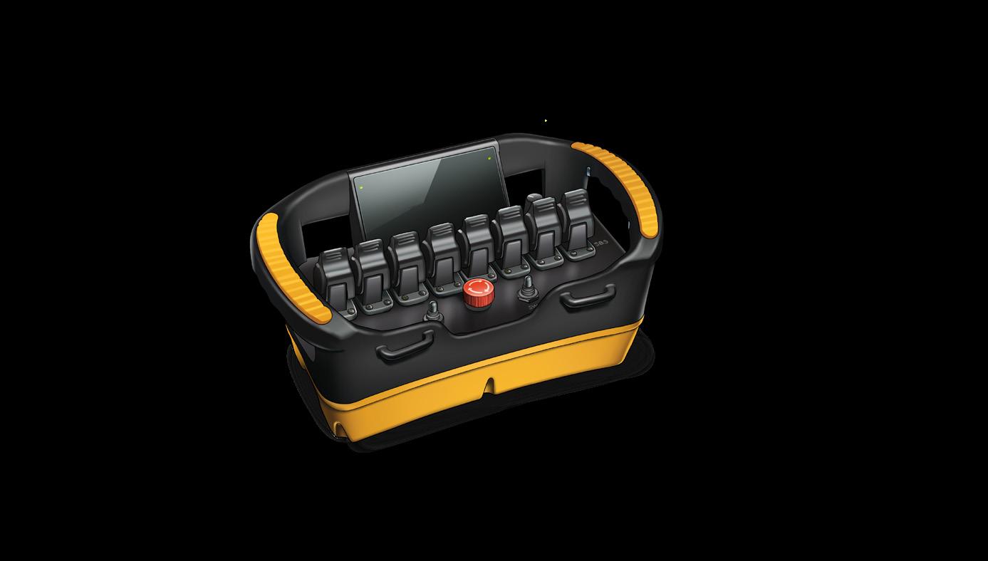
Electrified systems reduce the need for complex mechanical and hydraulic control systems, such as cable linkages and pilot-operated levers. Instead of multiple hydraulic valves and levers, a single electronic controller can manage multiple functions, reducing system complexity. What previously took a dozen levers to achieve with hydraulic joysticks (Figure 1) can now be achieved with a couple of analog joysticks with auxiliary control switchgear mounted atop.
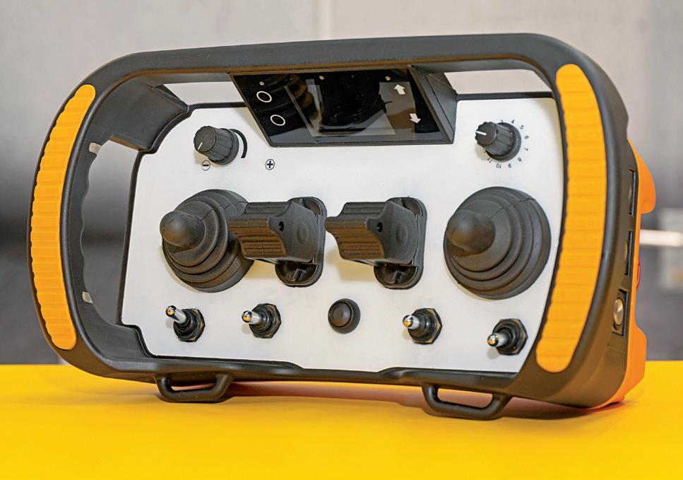
Even analog joysticks may have smaller thumb-actuated analog joysticks mounted to the upper portion alongside various possible rockers, toggles or pushbuttons, as seen in Figure 3. If you’ve played a console game system such as X-Box or Playstation, you’ll know just the types of control options available to today’s modern machines. As well, electronic controls reduce energy consumption by reducing the peak demand of the hydraulic system. For example, an older, complex machine will use power to supply the pilot circuit, which is essentially a mini hydraulic system within a hydraulic system.
FIGURE 2
FIGURE 3
Also, electronic control of hydraulics offers a more precise method to control flow and pressure. Old, human-adjusted pump and valve settings counted on the technician's expertise in handling them, which could lead to errors or oversight, especially when inexperience plays a part. I’ve seen many circumstances where components were poorly adjusted to increase performance yet resulted in wasted energy, such as raising the pump’s compensator setting above the relief valve setting.
One of the most productive benefits of electrified systems is that they can be controlled remotely and connected to networks, allowing for remote monitoring, diagnostics, and even control from a distance. This is useful in hazardous environments or where access is limited, or the operator is better suited to operate outside the machine.
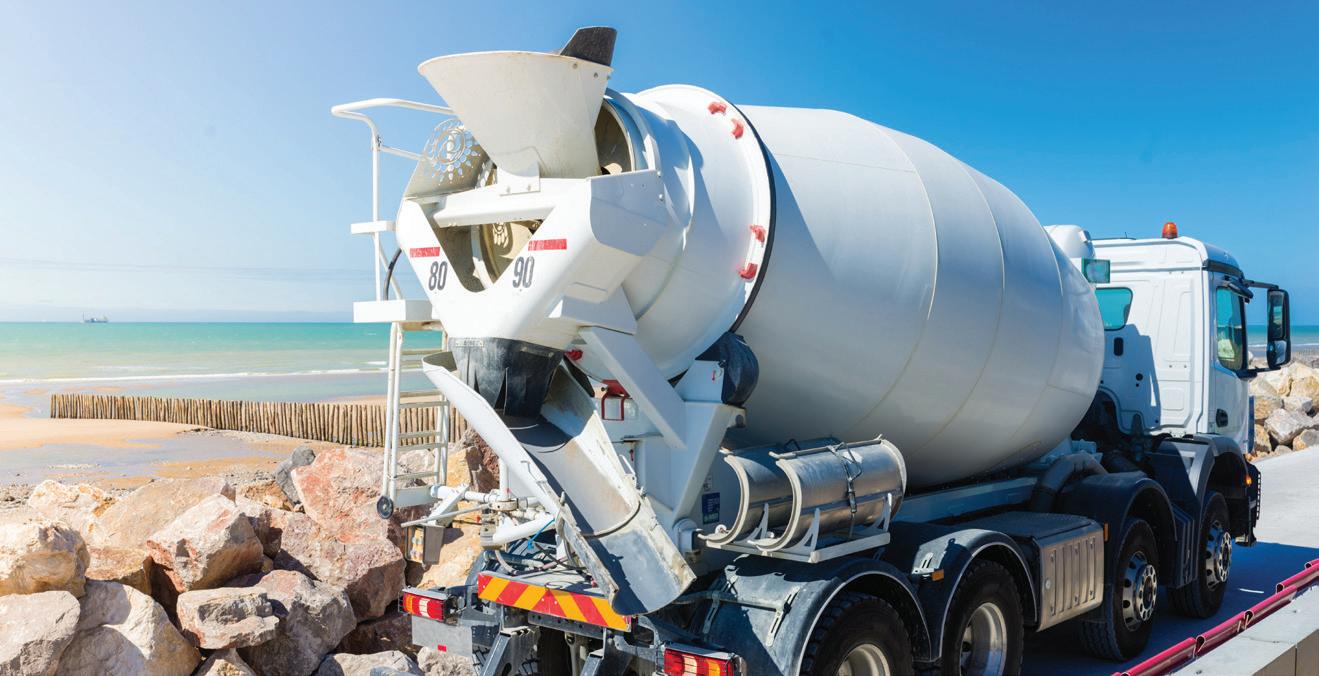
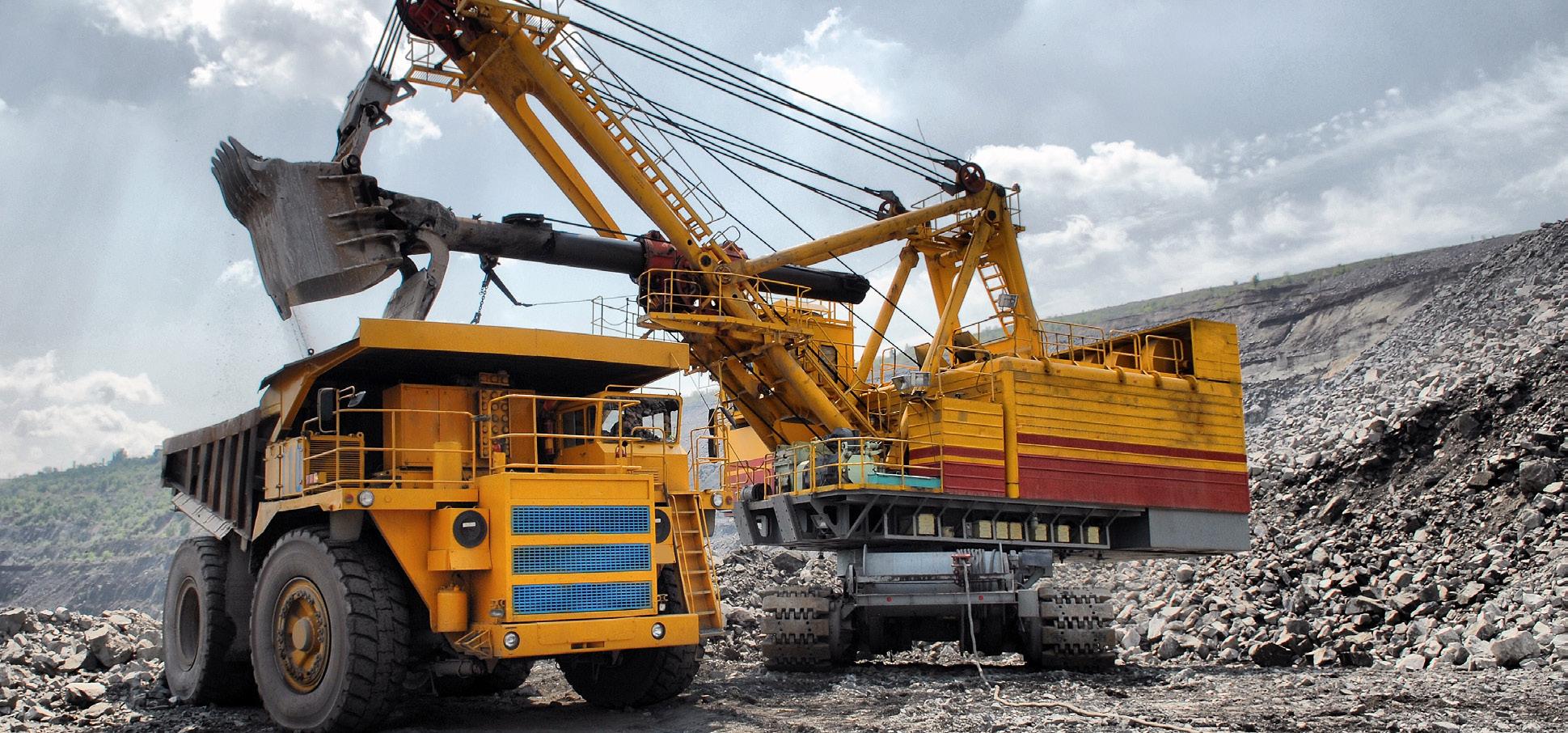
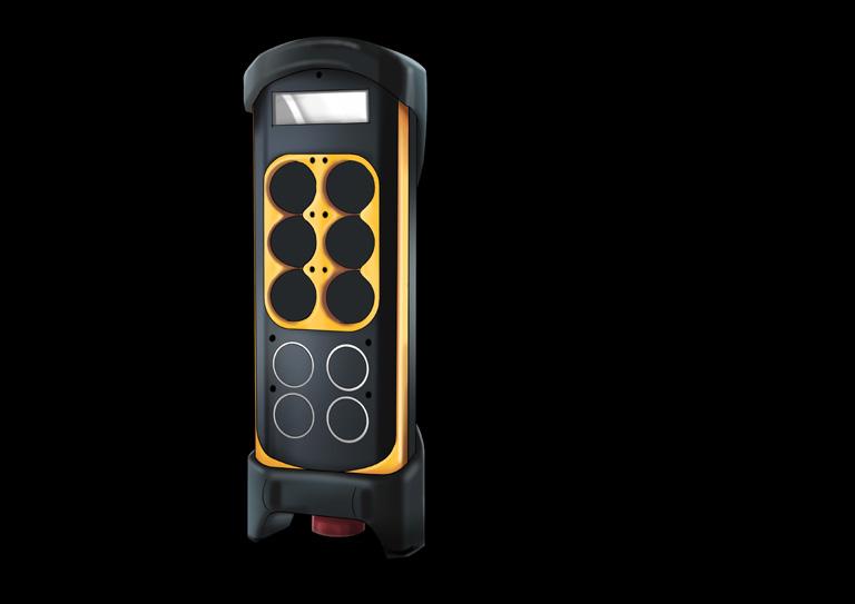
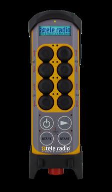
Cranes, stone slingers, tow trucks, forestry equipment, concrete pumps and min-
ing equipment all benefit from the proliferation of wireless remote-control technologies. Stone slingers, for example, use a belly-box style wireless remote control, Figure 4, to operate conveyor velocity, boom position and even vehicle creep speed. Imagine the truck parked outside a fence preventing easy access for dumping. The stone slinger operator can position their machine on the side opposite of the fence and precisely apply gravel, sand or dirt where needed.
Belly box controls come in various designs, from simple switch-based layouts to complex joystick configurations. They must take into consideration operator ergo-
Quality in Control.
nomics and machine complexity so that the operator can intuitively interact with the controls and the machine.
Electrified controls often result in fewer moving parts and reduced wear and tear compared to purely hydraulic systems. This can simplify maintenance routines and extend lifespan. There used to be concern over electronics in mobile machinery, particularly over the lack of backup systems should electronics fail. Many manufacturers select sandwich-style mobile valves using levers as backup control. Most designs come with proportional control, accessory valve ports, or even load sense circuits.
It used to be that electro-proportional control of mobile hydraulics required technical training to program and set up components and controllers. With the growth of inexpensive electronics, mobile devices, and workers who coded from the cradle, it's easier than ever to adopt electronic control. FPW
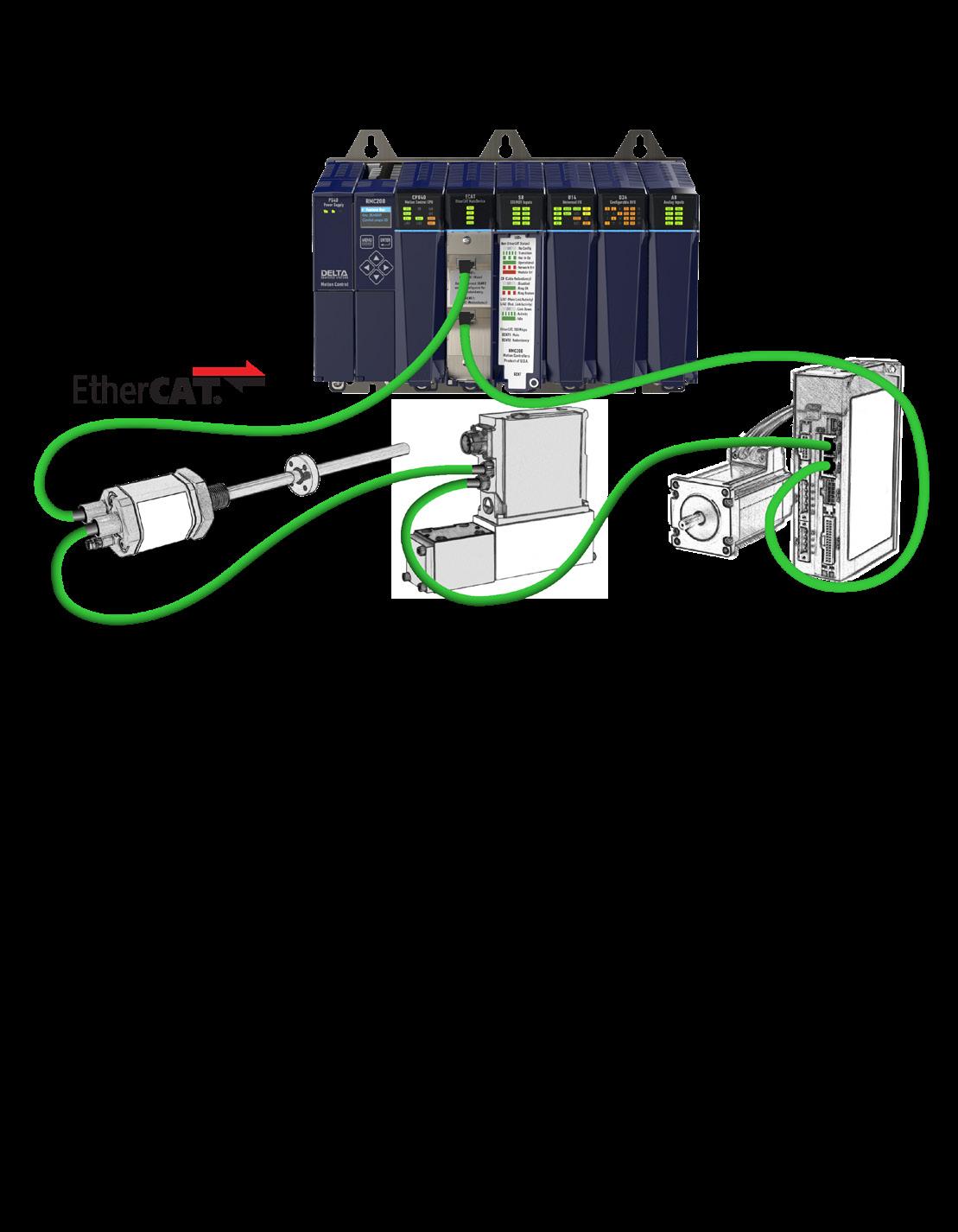
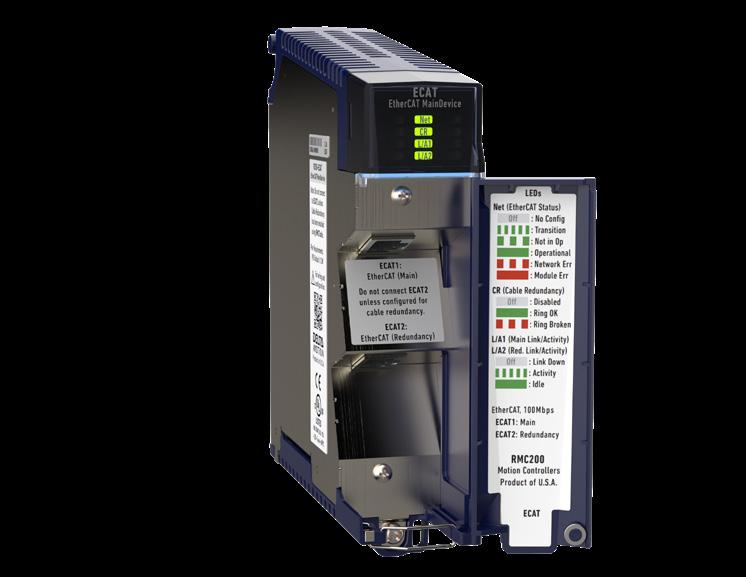
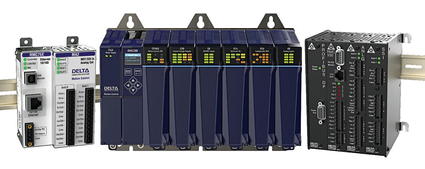
Drive Forward with EtherCAT from Delta Motion
How are motion controllers used in fluid power?
MOTION CONTROLLERS ARE USED EXTENSIVELY on industrial machinery, but controllers exist that are dedicated for use on electrohydraulic machinery. They provide closed-loop control of electrohydraulic and pneumatic applications from single to multi-axis systems.
Like all motion controllers, these computational devices reduce system error by taking an input command, comparing it to a feedback signal and helping to bring the position or output in line with the input or required position. They ensure precise pressure and force control while smoothly transitioning from position to force control.
This precise and repeatable motion improves productivity by reducing mistakes in manufacturing. Additionally, the multi-axis design of most controllers helps to reduce system design costs by allowing for synchronization, tight control of gearing through system changes, and camming of the gear ratio so the relationship between slave and master axis is expressed as a nonlinear equation.
Most motion controllers work in concert with position and pressure transducers and sensors, which send signals from data logging devices to the controllers. They can accept analog voltage or current signals. Additionally, they receive positional signals from encoders and may also output PWM (pulse width modulation) signals. In hydraulic designs, using a motion controller that provides analog control signals to drive proportional valves is best.
In a hydraulic system, these controllers ensure synchronous motion by controlling a servo or proportional valve. The controller then needs to work with the feedback devices, like encoders or pressure or position transducers, to create command trajectories for the motors to follow. The controller uses this data to create a motion profile to tell the motor where the load should be positioned and when and how fast it must move and when to stop.
Finally, easy programming of most motion controllers allows users to simply use built-in commands for complex motion profiles. Using advanced controllers and software allows easy graphical programming of control profiles.
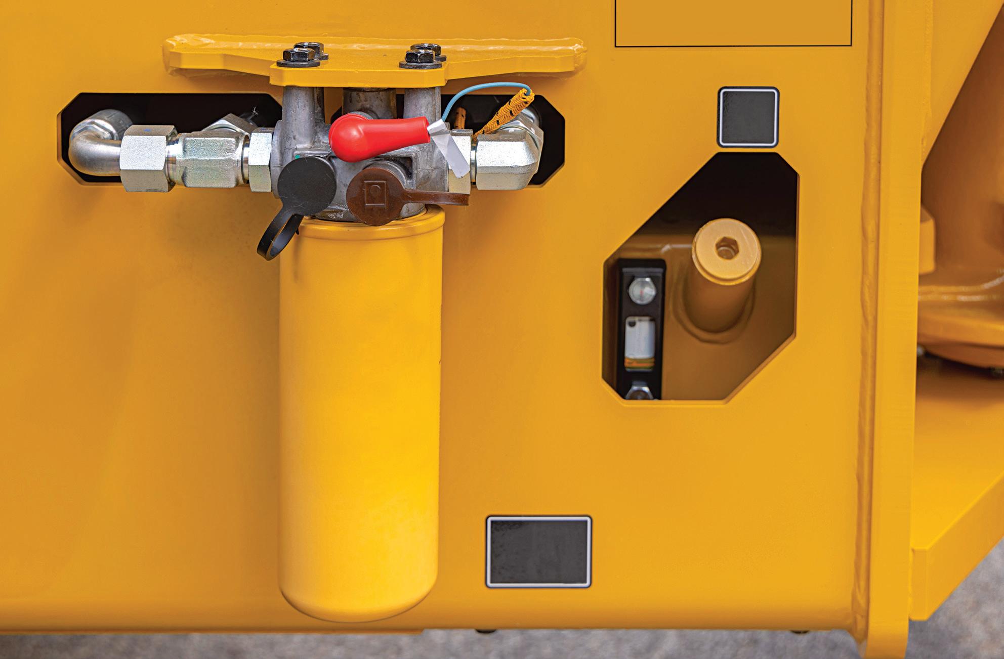
What are the symptoms of a clogged hydraulic filter?
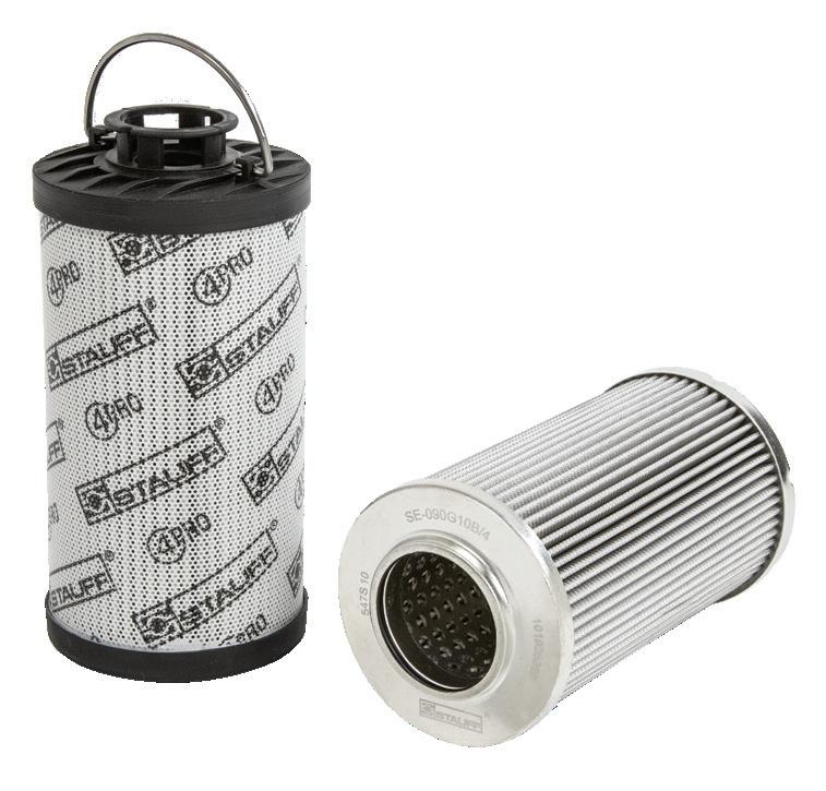
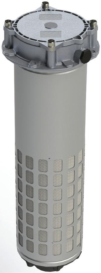
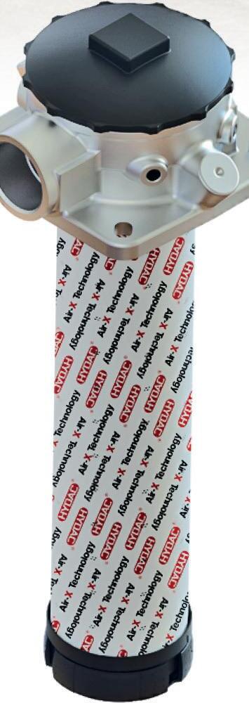
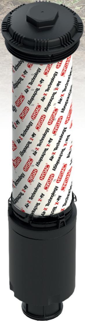
IN THE CASE OF HYDRAULIC SYSTEMS, efficiency and reliability are paramount, and these systems, used in various industries, rely on the seamless flow of hydraulic fluid to power heavy machinery and equipment. One crucial component that ensures the reliable operation of the pumps, valves and actuators is the hydraulic filter. This unassuming device plays a critical role in maintaining the integrity of hydraulic fluid by trapping contaminants and preventing them from circulating throughout the system, where they can wear or damage expensive components.
However, over time, hydraulic filters can become clogged, leading to a range of issues that can impact the performance of your machinery. Just so we're on the same page, I'm defining a clogged filter as one without a bypass valve. Nevertheless, you must know the signs of a clogged hydraulic filter and why it's essential to address this problem promptly.
A noticeable decrease in the performance of your hydraulic system is one of the first
One of the primary functions of a hydraulic filter is to prevent contaminants, such as dirt, debris, and metal particles, from entering the system.
signs of a clogged filter. You might observe slower or jerky movements, decreased lifting capacity, or reduced speed in your hydraulic equipment. This drop in performance (especially with an open circuit system) due to restricted fluid flow may have resulted from a clogged filter. As the filter becomes increasingly congested with contaminants, it creates backpressure in the tank line where it’s most nefarious, reducing pressure and flow available to everything upstream.
A clogged hydraulic filter can lead to elevated operating temperatures within the hydraulic system. As the filter restricts the flow of hydraulic fluid, it causes the fluid to
work harder to move through the system and often partially through the relief valve. Always remember that any fluid being lost in a hydraulic system before achieving useful work is manifested as pure heat.
One of the primary functions of a hydraulic filter is to prevent contaminants, such as dirt, debris, and metal particles, from entering the system. If the filter is clogged, it cannot effectively trap these impurities when fluid is taking the express bus right through the relief valve. Contaminated hydraulic fluid can cause severe damage to the system's components, including pumps, valves, and cylinders.
A clogged hydraulic filter can also manifest as an increase in maintenance requirements. If you find yourself constantly cleaning or replacing components within your hydraulic system, it could be a sign that the filter is not functioning correctly. Addressing the filter issue can reduce the overall maintenance needs of your machinery and save you both time and money in the long run.
In the worst-case scenario, a severely clogged hydraulic filter can lead to complete system failure. When the filter becomes entirely blocked, hydraulic fluid cannot flow through, causing a sudden shutdown of your equipment. This can result in costly downtime and potential safety risks in specific industrial settings.
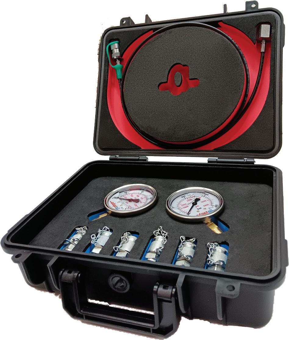
Suppose your machine has a filter and no bypass valve, which are more common than you might think. In that case, you must be absolutely sure to use differential pressure indicators to monitor the clogging status of your filter. These indicators can be simple pressure gauges, pop-up indicators or even electronic transducers. Because of the severe repercussions possible without a bypass valve, it can't be overstated how critical it is to monitor and replace your filter to prevent clogging. FPW
Electric versus hydraulic motors
COMPARING ELECTRICAL with hydraulics is one of my favorite topics to write about. When you study both fields, you quickly realize how much the concepts, mathematics and symbology coincide. However, not all readers share my same enthusiasm for the analogy. Many years ago, one LinkedIn member commented that I was writing too much about the topic and that the two fields aren't even comparable (to which I'm sure your author challenged proof to the contention, which I did not receive).
Before we get into a deep comparison between electric and hydraulic motors, let’s first review each concept and what makes them similar. Primarily, they’re both systems that transmit energy remotely and then convert it into mechanical force. They both provide precise control using various input methods. And they employ similar elements to achieve work: power source, transmission, control and actuators.
Looking at similarities
But it gets more precise when you dig deeper into two concepts. Let’s first discuss the nature of how each creates work. Both technologies use a medium that “pushes”
energy through conduits. Electrical voltage is the potential differential that drives the flow of electrons and the force to push through a conductor. Hydraulic pressure is also the force exerted to move hydraulic fluid through conduits, allowing flow to occur. Remember, flow occurs because pressure allows it, and pressure is not the resistance to flow, contrary to some myths.
We can also compare amperage and flow rate with the understanding that voltage and pressure drive electron and oil molecule movement. The total rate of electron flow through a conductor defines amperage, while the volume of hydraulic fluid through a pipe, hose or tube results in measured flow. Amperage is universally expressed in amperes (or amps for short), while flow can be expressed as either liters per minute or gallons per minute, depending on your geography.
The analogy continues with various calculations commonly (and not so commonly) used in each field. For example, the legendary Ohm's Law states that voltage drives current through a resistance and is expressed as V = IR. Although not a common expression in hydraulics, you could also posit that
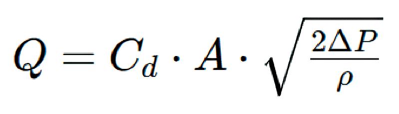
P = QR, where P is pressure, Q is flow, and R is the hydraulic resistance. Hydraulic resistance is more commonly referred to as backpressure or pressure drop, but you could get fancy and use this formula to calculate flow through an orifice:
I’m assigning no homework here, but if you wish to play around with the numbers:
Q = Flow in gpm
Cd = Discharge coefficient
A = Area of orifice in square inches
ΔP = Pressure drop across the orifice
р = Density of the fluid in slugs per cubic foot
Okay, I get it. Nobody in the fluid power ‘hood is using that formula, but I wanted to highlight the similar concepts of potential. In either case, the higher the voltage or pressure upstream of a resistance/restriction, the higher the amps or flow out the other end.
For a more precise comparison, let’s look at power. Simply, both formulas look like this:
Force x Moving Stuff = Power
For example, 24 volts x 2 amps = 48 W
For example, 3,000 psi x 5 gpm / 1,714 = 8.75 hp
If you're not convinced yet by the apparent physical similarities between electrics and hydraulics, please consider the following examples. To flow more electrons or oil, you need larger conductors or hoses. Any energy used in either system before achieving useful work is wasted as heat. The components used in either circuit are essentially the same function.
Let me elaborate on that last point a bit more. As a fluid power professional, I've discovered that electricians and electrical engi-
FIGURE 1
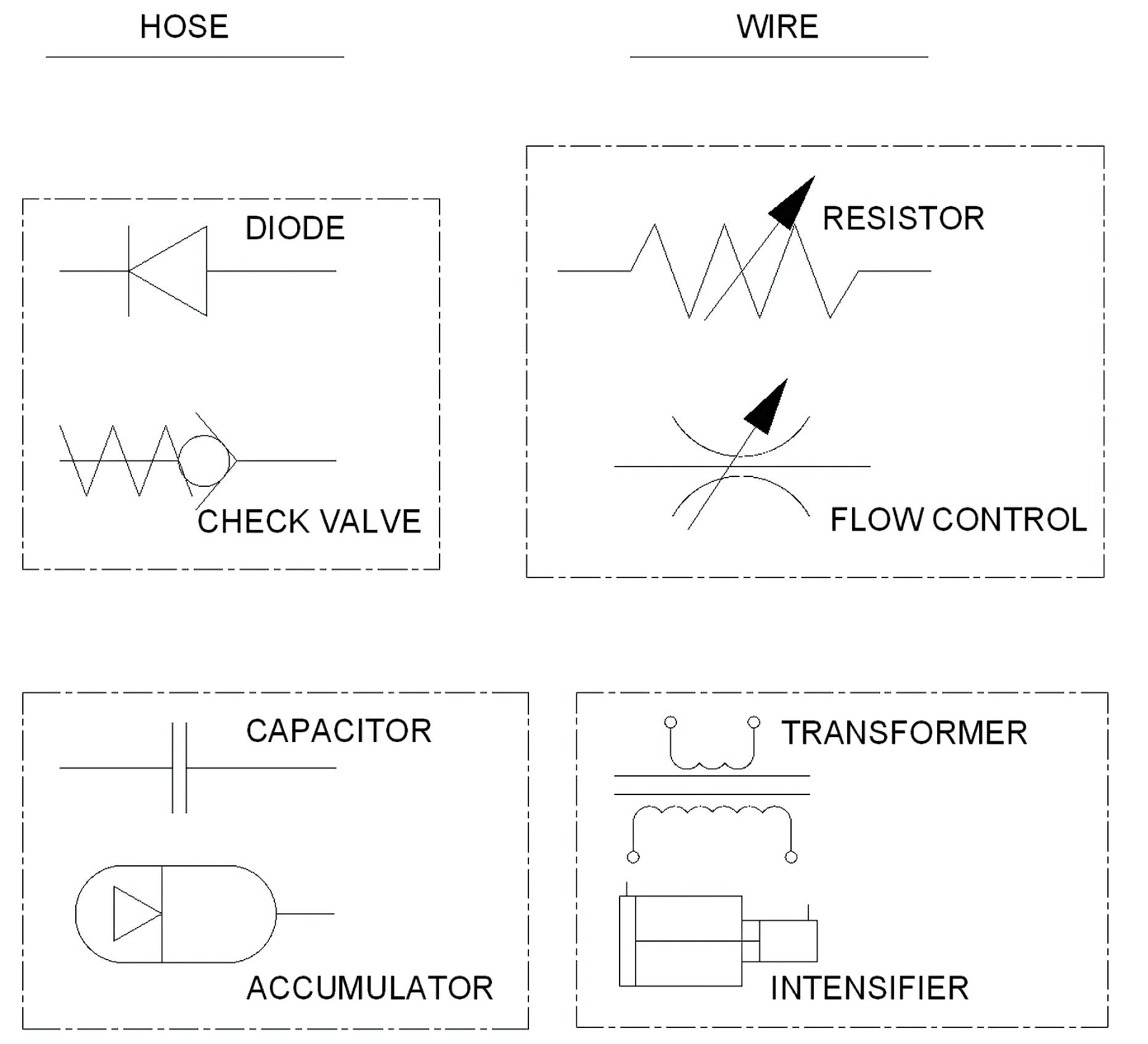
neers quickly absorb hydraulic knowledge not only because of everything I've discussed so far but also because the components and their circuit symbols are relatively similar. In hydraulics, we have a check valve. In electrics, we have a diode. Both allow flow in one direction while blocking in the reverse. In hydraulics, we have a flow control. In electrics, we have a resistor. Both restrict the flow of either oil or electrons, respectively. There are so many examples, in fact, that perhaps a list is more appropriate:
Hydraulic pump = power supply
Cylinder = linear motor
Accumulator = capacitor or battery
Lever valve = switch
Solenoid valve = transistor
Pressure-reducing valve = voltage regulator (or even Zener diode, perhaps?)
Additionally, many of the above technological cousins employ symbology that looks similar when you squint hard enough. Figure 1 shows four such symbols familiar to industry professionals. Modern circuit schematics do a great job of visually express-
Modern circuit schematics do a great job of visually expressing the role of a component through simple lines and shapes.
ing the role of a component through simple lines and shapes. For the diode and check valve, it's easy to see how their shapes allow for flow in the left direction only.
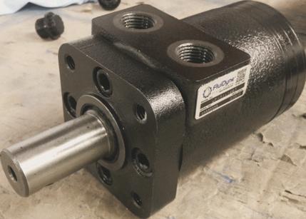
Motor designs
I hope you now agree that the principles of electrics and hydraulics are pretty similar, so let's get onto the subject at hand — electric versus hydraulic motors. Essentially, each device converts its fundamental energy into mechanical force in the form of torque (which is just force applied at a perpendicular distance from an axis). Other than an output shaft to appear similar, the two motors achieve force vastly differently.
An electric motor must first create a magnetic field, and it’s that field interaction that results in torque. They may use combinations
of permanent and electro-magnets with various methods to generate and control magnetic fields. Electric motors may use Direct or Alternating Current, or even sometimes both.
A hydraulic motor creates torque when pressure is applied to a surface area suited to rotational motion. That surface area could be pistons, vanes or gears, but the larger the surface area and distance from the axis, the more tangential force created.
As expected, larger motors create more torque, but that’s not the sole defining predictor of torque output. Hydraulic motors are much simpler to analyze for torque efficiency, but perhaps I say that only as a hydraulic professional. The torque output of a hydraulic motor is a combination of pressure, displacement, volumetric efficiency and mechanical efficiency, although factors such as load, viscosity, temperature and speed also play into the equation.
For electric motors, the situation becomes more complex. Mechanically, you must still deal with the elements that create a better “lever,” such as armature length, rotor radius and stator/rotor geometry, but also with properties that affect how much magnetic field you can create. The number, configuration and cross-section of windings, permanent magnet strength, inductance of the windings and temperature all play a role in electric motor torque.
The primary difference between how an electric motor operates compared to a hydraulic motor is the use of magnetic fields. Hydraulic pumps create hydraulic pressure that creates a column of flow pushing into the hydraulic motor, which directly rotates its output shaft. Conversely, electric motors must count upon the strength of their magnetic fields, and how strong those magnetic fields are depends on the variables outlined above.
It's generally been accurate to say that a hydraulic motor always produces more power than an electric one. For any given industrial electric motor, even today’s premium efficiency options, you can expect them to offer about 0.05-0.1 kW of power per kg of motor weight. However, when you start talking about high-performance servo motors, you can expect to achieve up to 2
kW/kg power density, which is pretty good.
If you're a fan of electric vehicles and have read up on them, you're probably aware there is a battle raging for electric motor power density supremacy. With the rapid innovation we've experienced in materials, construction and design, electric motors for vehicles have increased power density exponentially, and emerging technologies are pushing the boundaries toward hydraulic levels. The axial-flux motor, for example, has many startups producing models with over 10 kW/kg power density, and you can expect to see these in vehicles soon.
But is electric motor technology finally beating hydraulics? Not quite yet. Realistically, nobody in the fluid power industry necessarily focuses on power density as an end goal. We're just out here making efficient and powerful actuators that are powerdense by default. You won't find kW/kg in any hydraulic motor catalog either. But if you
did, there would be some clear winners.
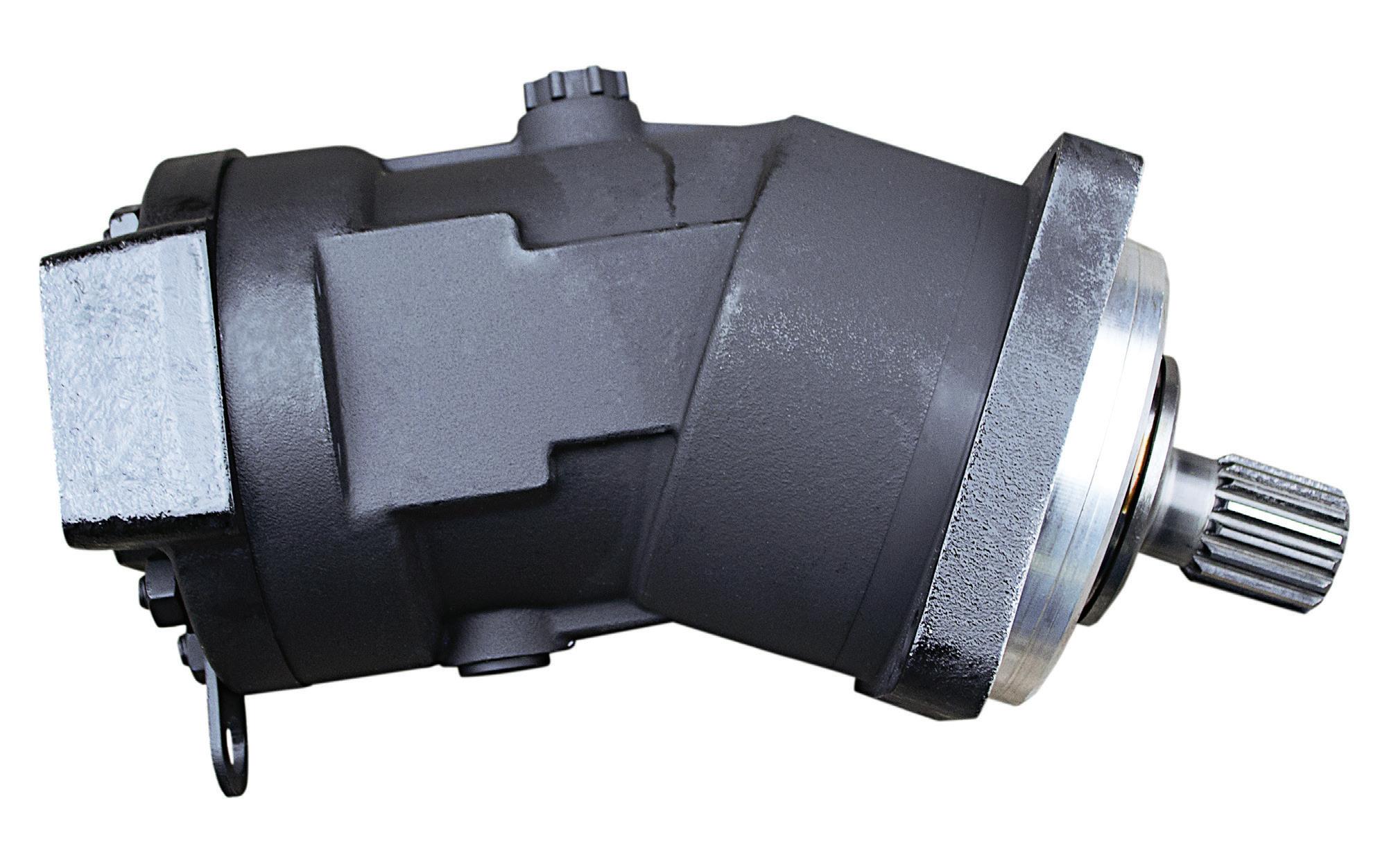
The bent-axis piston motor is hard to beat for power density. The Rexroth A2FM5 creates 10.35 kW/kg, or 26 kW or about 35 horsepower, continuously without breaking a sweat. No special cooling, exotic materials or technological advancements are required, and the modern design is based upon the technology Rexroth developed in the 70s. I know I’ve mentioned this motor series in the past, and I don’t mean to ignore all the other manufacturers here, but I’ve yet to see someone push the technology to this level.
"So what?" you might be saying, electric motors are already matching the A2FM's little 5 cc motor. Yes, maybe – but are they doing it in a housing that can fit into your empty Venti coffee cup? Indeed, this little motor is only six inches long, weighs just over five pounds and kicks out 35 hp.
And if you thought that was impressive, let’s talk about their 16 cc version of this
motor. At just over twice the weight and 115 hp continuous, it’s pegging the power density meter at nearly 20 kW/kg. Will electric motors ever achieve this kind of power density? It’s hard to say — magnetic saturation prevents materials from improving much past a certain point, and efforts to increase power result in the law of diminishing returns. Plus, it's just as likely that we'll be unable to cool higher-density motor units, limiting how much power we can make in a small package.
Ultimately, hydraulic motors are like the old boxer fighting in long pants and a white tank top. The axial flux motor is the young mixed martial artist getting all the attention for all the right reasons. But when push comes to shove, the axial flux motor will be surprised by the unexpected dad strength, experience and unwavering demeanor of the hydraulic motor, who has lots of fight left in him. FPW
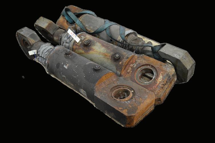
What is the life expectancy of a hydraulic cylinder?
IF YOU DIDN'T ALREADY KNOW, I work for a company that manufactures hydraulic cylinders. A common question from customers is, "What is the life expectancy of your hydraulic cylinders?" My response is often to take a deep breath and then sigh because the correct answer is never straightforward. The salesman in me likes to respond with "indefinitely" but is always followed up with "depends."
I like to compare the longevity of hydraulic cylinders to that of personal vehicles. It's common knowledge that when you properly care for your car, it can last indefinitely. Timely oil changes, dealer-recommended service intervals, regular cleaning and some tender loving care are what separates the Boomer from the '62 Impala running 500,000 miles from the Zoomer calling the scrap yard to collect $500 for their ’08 Corolla that died at 120,000 miles.
I would estimate that the majority of cylinders we sell are less than a couple of grand investment cost, so one might think
it's easy to forsake a cylinder compared to an exponentially more expensive vehicle. For what it's worth, we sell many cylinders more expensive than what is the mind-blowing, average new vehicle price of close to $50k, but it’s not really the point. Some cylinders are installed on machines costing many multiples of that new car average, and those machines produce revenue for the company many times than what that machine costs as well. The point is that hydraulic cylinders are essential in their roles and should be treated as the tools they are to create revenue for your company.
You want all your hydraulic cylinders lasting as long as possible, and being mindful of what makes a cylinder reliable spells the difference between a Temu rate of failure and Toyota Land Cruiser dependability. Anyway, enough with the fluffy metaphors; you want facts on actual cylinder lifespan.
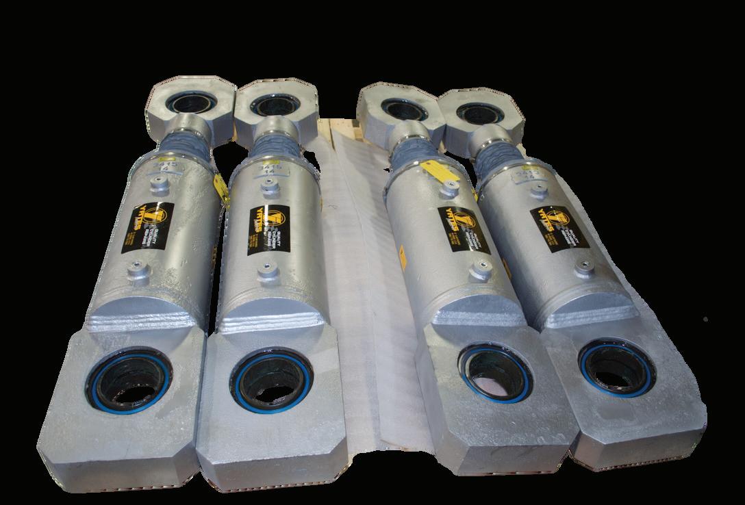
When treated well, there's no reason your cylinders shouldn't last twenty years or longer as long as they were built well to
start. But because the primary components are various forms of metal, and all the wear surfaces offer replaceable parts, there's no reason a cylinder shouldn’t last the life of the machine.
Let’s assume that the head, cap and tie rods never need replacing. That leaves the piston rod and barrel, both of which sometimes do wear. However, both these items can be refreshed easily with an application of chrome. The bushing is a wear item but requires replacing less frequently than the seals and wear strips. Finally, so long as the wear strips are replaced as required and the tube is kept within spec, the cast iron piston should also last indefinitely.
Just as with all hydraulic components in your system, high quality filtration prevents excessive wear of the sealing package. Because cylinders reciprocate, any particles within the oil may score across the rod to barrel, damaging not only the seals but also the rod and tube. As pressure rises, particles are able to push through gaps with more vigor, which is why high pressure systems should employ extra-fine filtration.
And finally, we cannot ignore the design and installation aspects of the cylinder within the machine. The nature of the forces on the rod, the column strength of long cylinders, the quality of the wiper seal, and prevention of side load forces all play a role in reliability. It doesn't matter how high quality the cylinder is when its subjected to abuse – it'll fail prematurely.
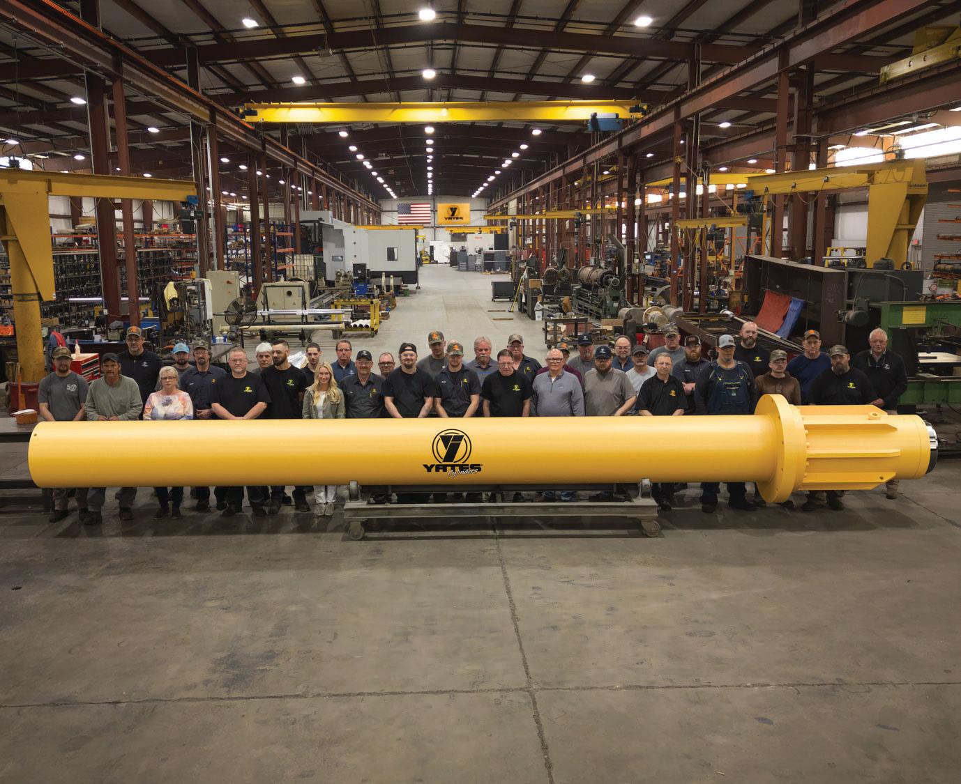
Hydraulic cylinders are work horses designed with a high safety factor to prevent operation at the cusp of failure. They’re essentially overbuilt for their purpose, and if they’re provided the respect they deserve, they will last a lifetime. FPW
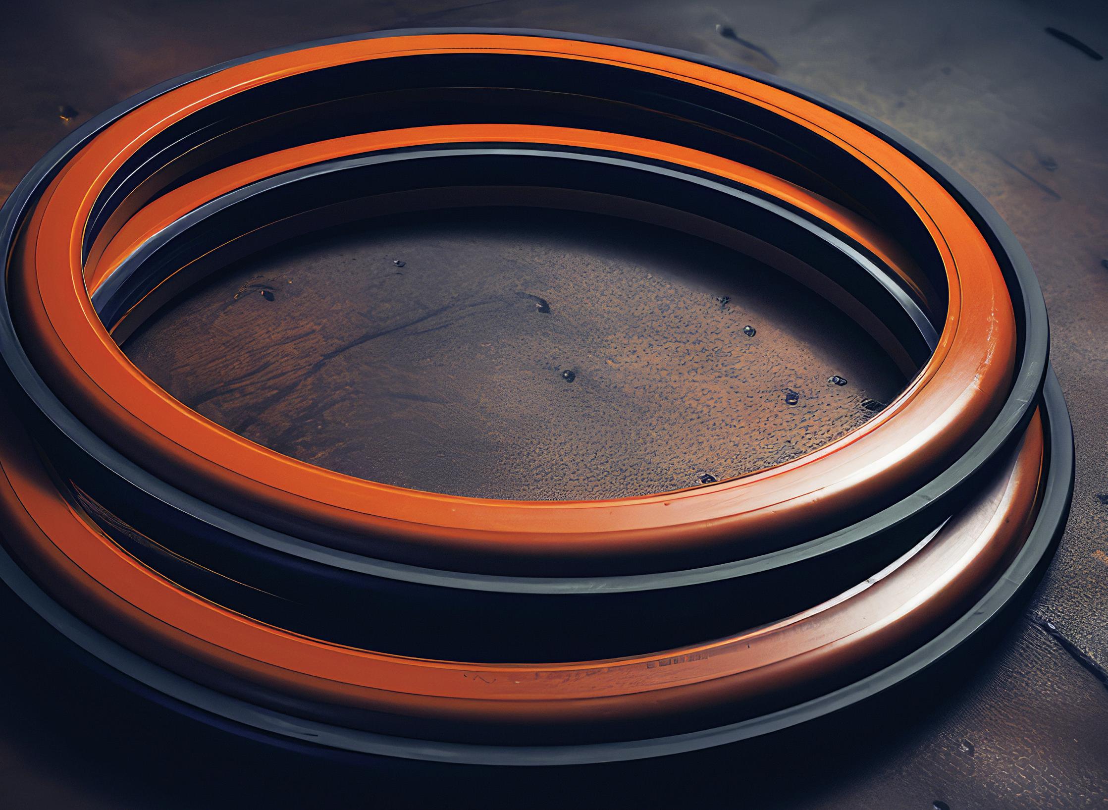
What are buffer seals?
SOMETIMES, THERE’S A PRACTICAL
and propitious device that’s been around forever, only to be discovered by happenstance, yet it provides immense value and serendipity. I have been known to use hyperbole in my writing, and maybe so here. Still, if this article convinces just one reader to use this simple solution to solve a simple problem, then I’m happy to use interesting language as my plea.
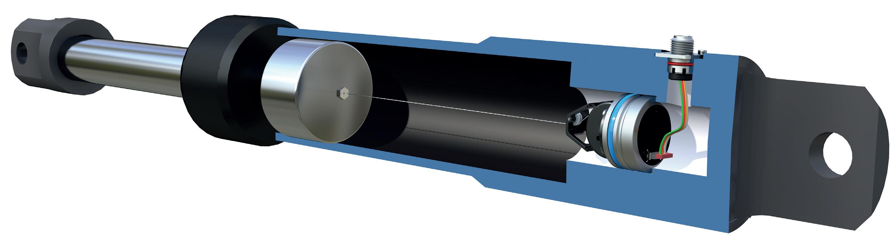
Leaking rod seals are not a new problem we experience in fluid power. For one of many reasons, your rod seal(s) may become damaged to the point of leakage: excessive pressure, incompatible fluids, physical impact, contamination or pressure spikes. The latter is the least obvious and most curious. It’s not likely you have a method to measure pressure transients, but they certainly affect seals deleteriously.
In a differential hydraulic cylinder, pressure spikes occur in two primary ways, although the actual list is not exclusive to
Adding a barrier ahead of the rod seal solves the pressure spike problem, and a buffer seal is engineered for the task. Its shape and material enable it to take a blow like a punching bag and then spring back to its usual shape.
these options. The first method is loadinduced tension events upon the rod, such as when the cylinder bottoms out or is tugged upon unexpectedly. Additionally, pressure spikes may occur due to decompression shock, where a large volume of piston-side oil under pressure suddenly releases its energy, bouncing the piston rod-side.
Regardless of the reason for the pres-
sure spike, these sudden transients can damage traditional rod seals. They are more often designed for static or steadystate conditions, which are rarely higher than the combination of load and breakaway pressure. A sudden spike, or a series of them, could cause the extrusion of the seal through tiny clearances, plastic deformation or even outright breakage.
Adding a barrier ahead of the rod seal solves the pressure spike problem, and a buffer seal is engineered for the task. Its shape and material enable it to take a blow like a punching bag and then spring back to its usual shape. A softer durometer rubber and more subdued cross-section create a damping effect that prevents the pressure transient from fully impacting the regular rod seal.
In extreme conditions, multiple buffer seals may also be used. Other than the extra material required in the cylinder’s head and/or gland, the only downside is the cost of the seal itself, which is nominal.
It is essential to realize that the buffer seal cannot act alone in sealing the rod side of a cylinder. They’re engineered to permit some leakage and aren’t usually an interference fit capable of holding a load. I’ve worked on an application where three buffer seals replaced the rod seal because the customer prioritized frequency response over load-holding, but this application included a gland drain to shuttle away leakage oil.
Buffer seals are an inexpensive and easy-to-implement layer of protection for demanding cylinder applications, but they are surprisingly uncommon. If you have a dynamic, high-load application that, in its current design, is chewing up rod seals, talk to your seal or cylinder guys to see if a buffer seal will suit your application. FPW
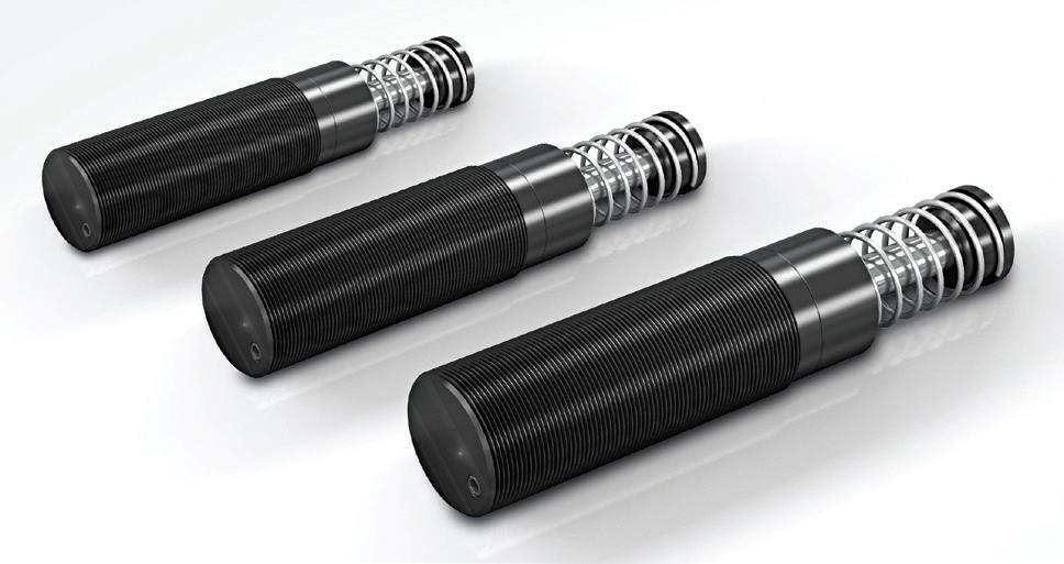
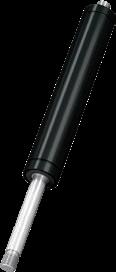
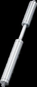
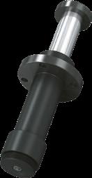
How do you size industrial shock absorbers?
SHOCK ABSORBERS PROVIDE controlled deceleration by converting kinetic energy to thermal energy. They’re used in a wide range of applications, from automotive manufacturing and lumber processing to robots, cranes and packaging equipment.
Sizing a shock absorber is relatively straightforward. Several reputable manufacturers offer online calculators, but here are a few guidelines to come up with suitable products.
Manufacturers’ web sites and data sheets typically list products by parameters like stroke, usable velocity range, maximum amount of energy that can be absorbed per cycle, maximum force capacity, and the maximum propelling force it can handle, as well as dimensions and other relevant details. Before sizing a shock absorber, however, users first need to determine the relevant operating conditions, including the weight and velocity of the moving mass and how frequently the shock is loaded. For simplicity, let’s look at a linear-motion application and use Imperial units for the calculations.
Determine kinetic energy in the system from:
Ek = W/(722)(V2)
where Ek = kinetic energy, lb-in.; W = weight of moving mass, lb; and V = velocity of moving mass, in./sec. This equation represents the amount of kinetic energy that the shock absorber will convert to thermal energy on each impact.
Next calculate the work energy in the application, defined as the amount of energy an external device generates to move the load:
Ew = Fd(S)
where Ew = work or drive energy, lb- in.; Fd = drive force, lb; and S = stroke of the shock absorber, in. Note that Fd should not exceed the unit’s maximum rated propelling force. If it does, select a larger size and recalculate the work energy.
The next step is to calculate the total energy, Et (lb-in.) per cycle, shown as:
Et = Ek + Ew.
Again, if this exceeds the model’s energyabsorbing capacity, select a larger unit and recalculate the work energy. Otherwise, the shock’s temperature may rise beyond rated limits and critical internal components like hydraulic seals could fail.
If the application uses more than one shock absorber, divide the total energy Et by the number of shocks to determine the total energy per shock.
Then determine the total energy a unit must convert in one hour. That’s because even though a shock might absorb an acceptable amount of energy in a single impact, it might not be able to dissipate the generated heat if the cycle rate is too fast. Here, multiply Et by C, the total number of cycles per hour:
Etc = Et(C)
The device’s hourly capacity must exceed this calculated amount. If not, choose a larger absorber (and recalculate Ew if the stroke changes) or, possibly, add an external oil tank or a cooling device to help dissipate the heat.
Finally, consider the shock force, Fp (lb) in the application. Shock force, in essence, is the resistive force required by the shock absorber to stop the moving load:
Fp = Et/(Sη) where S = the stroke of the shock absorber and η is the unit’s damping efficiency. While the efficiency can vary with the type and model, 85% efficiency is a good baseline for typical industrial shocks.
When to use (or not use) BSPT fittings
IF YOU’RE NOT TERRIBLY FAMILIAR
with hydraulic fittings, you may think BSPT is a typo. Is it supposed to be BSPP (British Standard Pipe Parallel) or perhaps NPT (National Pipe Thread)? No, it’s not a typo — we’re actually talking about British Standard Pipe Taper, which is the version of NPT created across the pond, because during fluid power infancy, everyone thought they had a better mousetrap.
Regardless, it’s here and more popular than you’d think. Before discussing when or not to use BSPT threads, let’s look at what defines the standard. As a tapered thread, it was designed to tighten as the male is forced into the female and torqued. This interference fit connection is meant to seal across the threads' flanks, although a thread sealant is often required to complete the task.
BSPT is actually very close to NPT, except that NPT has 60° flank angles while BSPT has 55° flank angles. That five-degree difference isn’t enough on its own to say they’re
incompatible, although using a BSPT male inside an NPT female port may result in more leakage because of the 2.5° gap on each side of the flank. What prevents compatibility is the thread pitch of each standard for which each is available.
You can see from the chart that only ½ in. and ¾ in. threads share the 14-pitch distance. The pitch is the distance between each thread, which we describe as threads per inch when referring to imperial threads. If you attempt to use any other size thread with its competing thread form, you’ll be lucky to achieve one complete turn before the fitting stops dead entirely.
To answer the question proposed in the title of this article, the time to use BSPT fittings is when the components you’re using or have purchased are with BSPT ports. You’re likely living in, or buying from, Asia, Europe or Africa, where BSPT is popular. “But Josh, all the pumps we buy from Asia have an Rc port in their catalogs.” You, my friend,
have BSPT ports, which is just another designation for Rc. Yes, I get how annoying it is to have so many different thread standards, let alone different names for the same thread (I’m looking at G Thread).
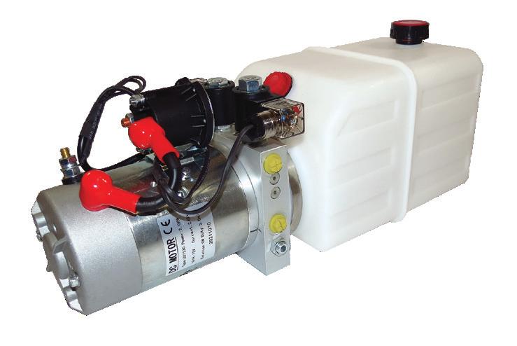
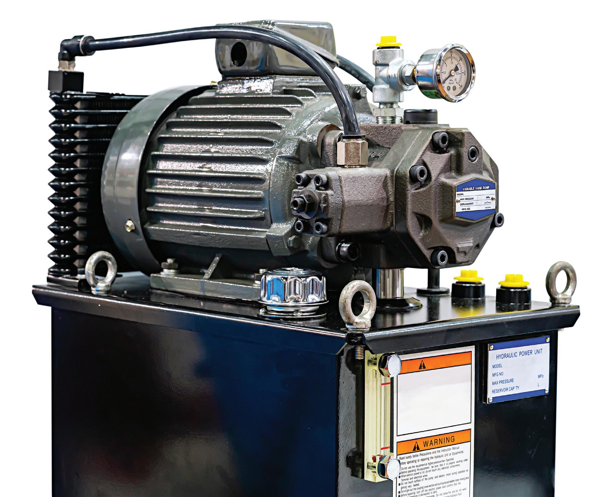
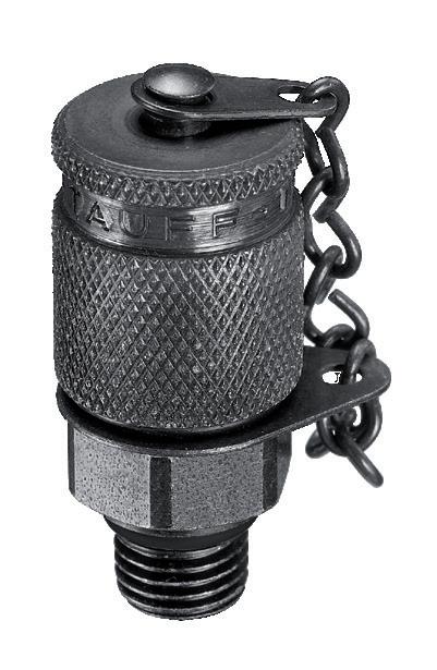
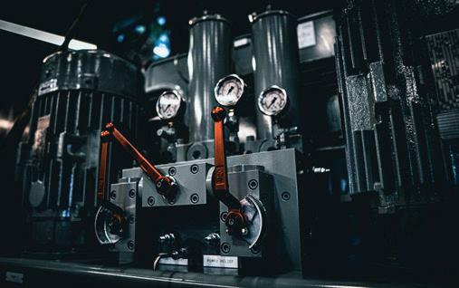
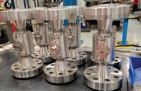
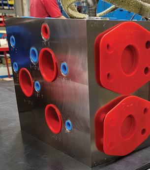
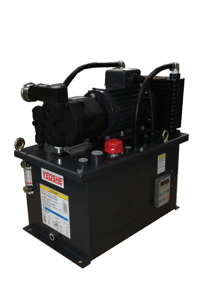
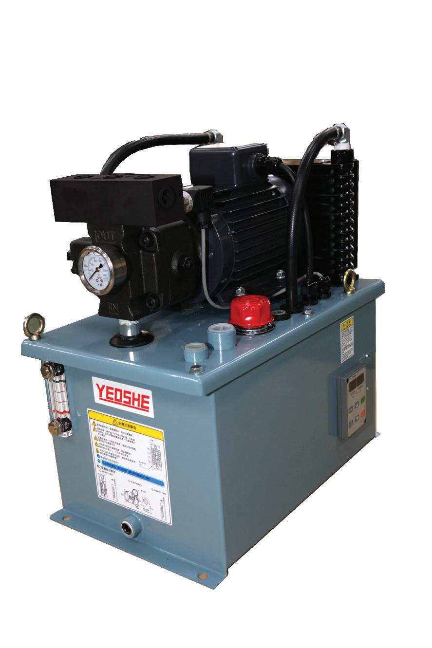
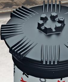
In fact, it’s likely you already have hydraulic components with BSPT ports. The machine tool industry uses compact hydraulic power units (Figure 1) for operation functions such as chucks and clamps. It’s likely you have one such power unit on your CNC mill or lathe, and it’s likely filled with BSPT ports on all the components.
Nevertheless, what’s important to remember is that BSPT is a tapered thread. Regular readers will know how I feel about tapered threads in hydraulics, and all my precautions apply in this case. A tapered thread should not be used when fittings are installed and removed frequently. I’ll concede that tapered threads work fine once installed and left alone for life. But the act of tightening a tapered thread deforms it, which is entirely the point. Reinstalling and torquing a used NPT fitting is a recipe for leaks, sometimes despite thread sealant.
You’re not likely to see the death of BSPT any time soon — the market is flooded with these products, and they are sold in the millions. Why would a manufacturer obsolete a cash cow design? If you come across a hydraulic component that appears to have NPT, yet none of the random fittings in your tool cabinet’s junk drawing fit, you likely have BSPT on your hands. Don’t stress — accept it and make friends with your local hydraulic shop carrying the widest selection of adapters.
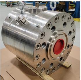
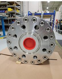
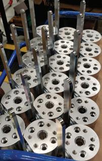
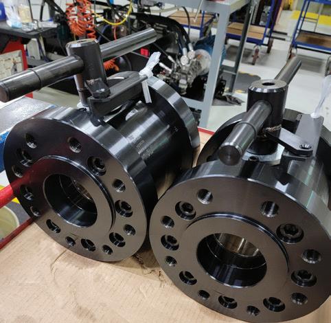
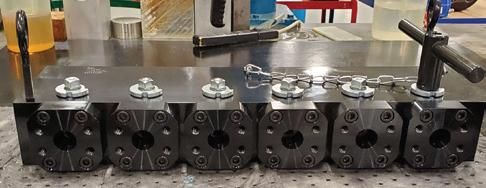
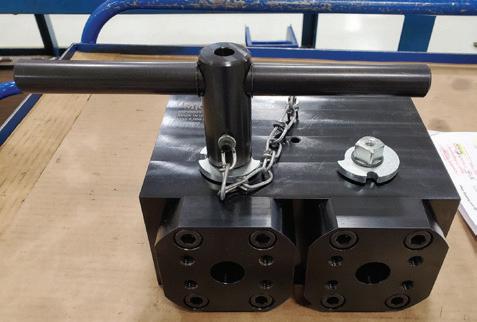
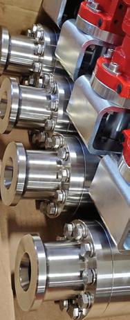
When should you use welded or bolted flange connection systems?
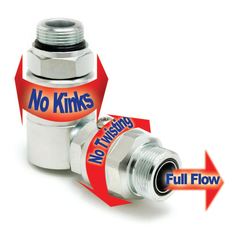
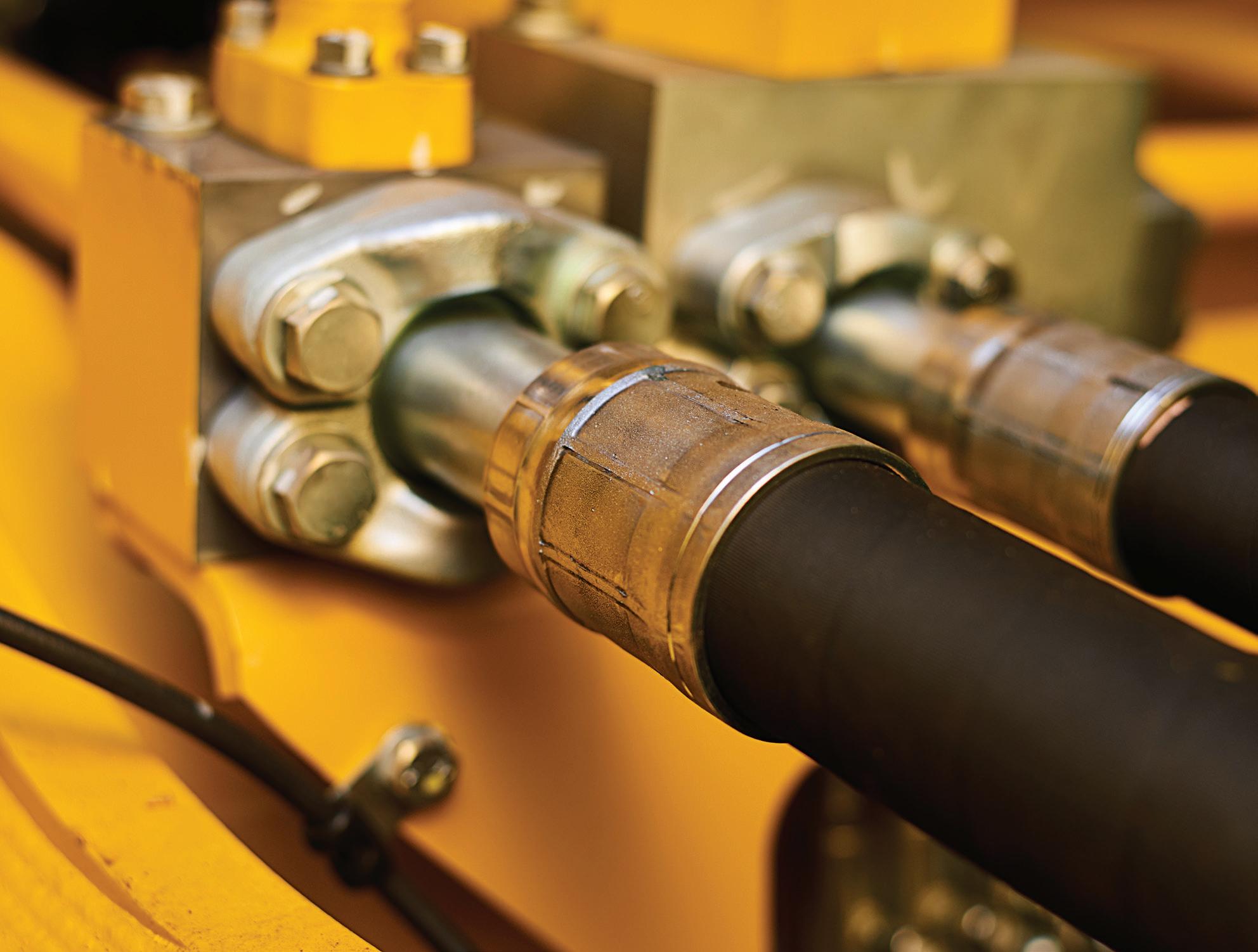
THERE ARE THREE WAYS to plumb a hydraulic system — rigid systems, flexible systems or a combination of the two. Rigid systems include pipe and various forms of tube, while flexible systems are assembled using only hydraulic hose. Most machines today are created using a combination of fixed plumbing, where no movement needs to occur, and flexible plumbing (hoses), where bending and flexibility are required. A common form of fluid connection for modern hydraulics is the flange. These are available in a few international standards, and what you use will depend on where you live. The SAE J518 style is commonly used in North America in their Code 61 and Code 62 variations. And if you’re in other parts of the world, those standards could be ISO 6164, CETOP or JIS B 2291.
No matter the standard, they’re all a great way to connect plumbing to your pumps, cylinders, motors, valves and manifolds. There is no need to twist or turn the hose or tube to tighten the connection, as is required with other connection threads such as NPT or BSPP. For a flange, you only need to place the flange against the port, install four bolts, and tighten it to spec.
A welded flange is machined with a conical bevel to provide a pocket for the weld bead to reside. Without this bevel, a butt weld would offer little to no strength, especially at high pressure. When installing permanent plumbing, the flange is first bolted in place, and then the terminating end of the tube, which also has a bevel, is tack welded into place to be completed later. If you’re sure the final tube assembly sits as it will for its final iteration, the tube may be welded to the flange entirely. Just remember to do so without the flange O-ring installed.
A welded flange can be used to connect manifolds, junctions or inline joints, as well as for the ports of components. Realistically,
Whether welded or bolted, the flange connection is growing in popularity due to its ease of installation, strength of connection and simple maintenance requirements.
and especially for industrial installations, fixed plumbing may be suitable for an entire machine. Many industrial machines have no pivoting joints that require a hose, and the result is a permanent solution with little to no maintenance required.
A bolted flange is one where an intermediate connection must be used to join the plumbing to the port. The flange will be thicker than weld flanges, as there must be enough depth to allow a port to be drilled and tapped into it. The port can be of any
traditionally available to hydraulics, such as NPT, ORB, BSPP, or metric. Those female ports will then employ an adapter of some sort to provide the actual plumbing connection, which, again, may be tube or hose.
The JIC male adapter installed into the flange makes a popular choice, mainly because of the ease of installing a female hose that ends with a swivel. One of the various tube connections that uses ferrules or other locking devices makes a semi-permanent connection nearly as rigid as a weld connection.
Whether welded or bolted, the flange connection is growing in popularity due to its ease of installation, strength of connection and simple maintenance requirements. If you’re plumbing your system from scratch, a solid plan using welded flanges provides the best long-term solution. However, upgrades or rebuilds might benefit from the flexibility of bolted flange connections. FPW
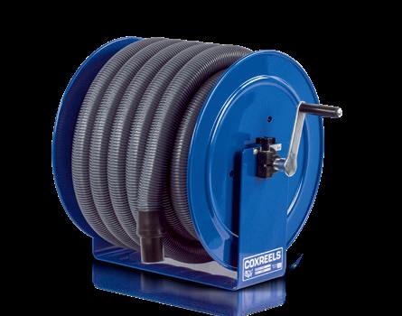
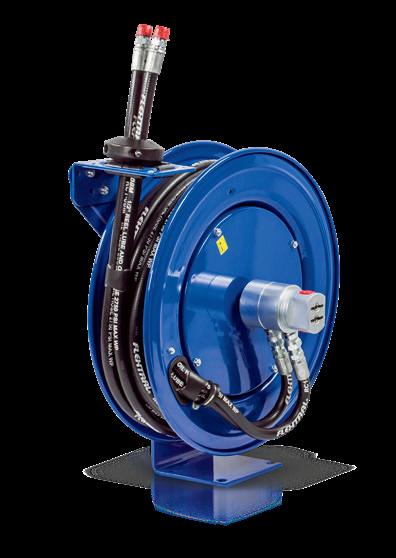
www. coxreels .com
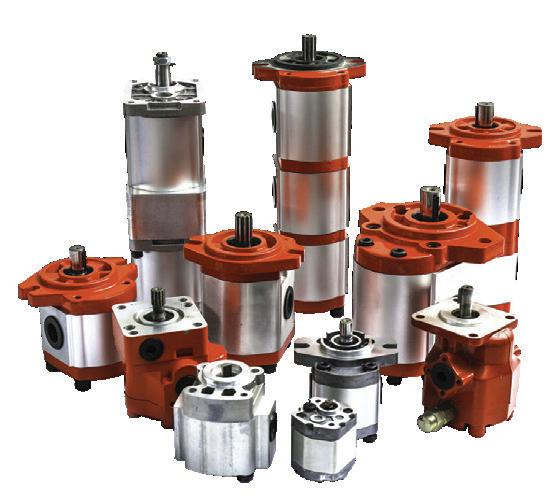
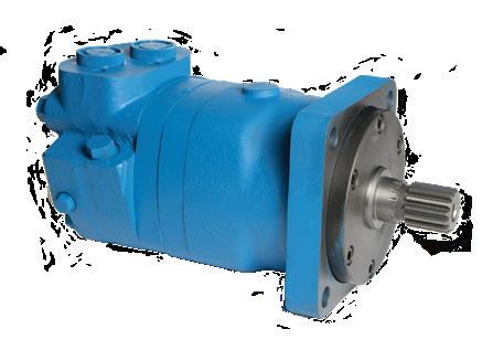
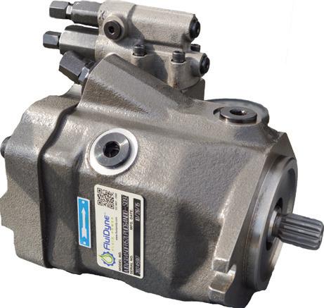
When should you use hydrostatic pumps?
THE TERM HYDROSTATIC refers to the fundamental concept we hold dear in fluid power, which is that confined hydraulic fluid under pressure exists in equilibrium and balance. Although hydraulic fluid does no more than hold objects stationary without the active application of force through a pumping device, the concept is entirely different than hydrodynamics, which recruits liquid molecules to create kinetic energy to achieve work.
So, if all hydraulic pumps are hydrostatic, what makes a hydrostatic pump different, and when should you use it? Hydraulic pumps, by and large, are used to create hydraulic pressure and flow for hydraulic systems of non-specific applications and purposes. However, the hydrostatic version is still a hydraulic pump but one specialized for closedloop hydraulic systems.
A closed-loop hydraulic system is one where the fluid exiting the pump flows directly to the actuator (usually a motor) to perform work before returning directly to the pump. A hydrostatic closed-loop drive provides a dedicated, controlled source of hydraulic energy to an actuator without the accoutrement of traditional open-loop (fixed flow) hydraulic systems, such as reservoirs, valves and accessories.
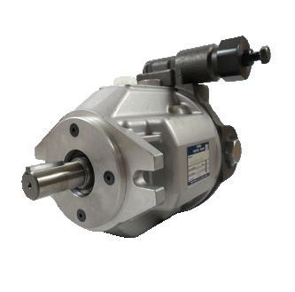
The variable displacement, pressure-compensated hydrostatic piston pump includes its own specialized componentry to support such a dedicated and otherwise sketchy task. In fact, at first glance, you
THE EAGLE HAS LANDED
would question the decision to river hot, dirty hydraulic oil through a pump motor combination, which would seemingly last only a few hours. Suffice it to say, it’s not that simple, or they wouldn’t exist.
The hydrostatic pump doesn’t operate using a reservoir, per se, because fluid flows through a dedicated circuit to and from the motor, although reservoirs often exist on the machines where these systems are installed. Instead, the drive package has a mediumpressure charge circuit that bleeds off hot oil, filters the fluid and replenishes clean, cool oil to keep it fresh. Cooling systems on mobile machines are robust enough to tackle the high heat load and are often hydraulically driven themselves.
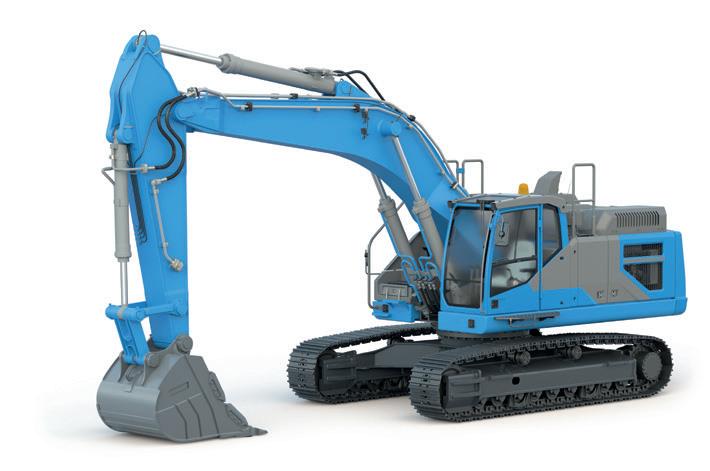
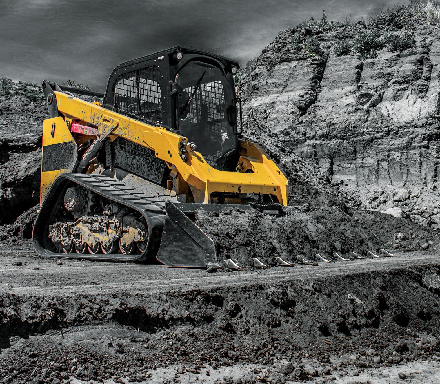
The most common uses for hydrostatic pumps are drives for mobile machinery, such as bulldozers, skid steer loaders, and excavators. Typically, you see two pumps driving two motors, each on either side of
the vehicle, which allows the independent operation required for steering. Hydrostatic pumps typically run over center, meaning their flow direction is reversible, allowing backwards travel without any traditional gear-driven transmission. In fact, the drive wheels can turn in opposite directions so the machine can pivot on-center.
Any application that can use a high-powered, efficient and versatile power transmission method is suitable for a hydrostatic pump. From landscaping to agriculture or from material handling to marine, these industries have various machines taking advantage of closed-loop drives. Lawnmowers offer zero-turn functionality, for example, and mobile shredding trucks offer robust, compact systems that run off the truck’s PTO.
Manufacturers have explored using hydrostatic pumps for advanced energy-saving concepts, such as the hydraulic hybrid
system for delivery vehicles and garbage trucks. Using a hydrostatic motor that also works as a pump, the kinetic energy of the slowing vehicle attached to the transmission pumps fluid into accumulators as the vehicle flows. These accumulators then release the stored energy as the vehicle accelerates, reducing the demand from the internal combustion engine, thereby saving fuel and reducing CO2 emissions.
If you’re considering a hydrostatic pump for your application, consider whether you need a dedicated drive system or one with various valves and actuators instead. Also, consider if you need variable speed, torque and power from your motor, especially with dynamic changes from moment to moment. Finally, consider cost, as hydrostatic drives are a premium option that puts productivity ahead of price. If these considerations meet your requirements, a hydrostatic pump provides a perfect solution. FPW
A round-up of hydraulic oil analysis tests
LABORATORY-BASED HYDRAULIC OIL
ANALYSES are critical to your predictive maintenance program. Each one of these parameters is tested by your local oil analysis lab from a sample collected from one or more of your power units. Read on to learn what the many tests are and what they encompass.
Viscosity – The quality described as oil's resistance to flow, or generally speaking, how thick or thin it is. Knowing the measured viscosity of your oil is vital to understanding the potential pitfalls of oil falling outside the ideal range optimal for your machine. Thick oil leads to wasted energy, cavitation and poor lubrication, while thin oil results in excessive leakage, rapid wear and overheating.
Your lab will first heat the oil to 40°C (104°F) and then run it through a kinematic viscosity test to confirm or deny it matches specifications. They can then rerun the test at 100°C (212°C) to calculate the viscosity index, which is a measure of hydraulic oil's tendency to maintain its viscosity over a wide temperature range.
Particles – The bits of contamination inside your hydraulic system that scratch, score and wear important and necessary internal components. They wear pistons, gears, vanes, spools, bodies, and sealing surfaces, making particle contamination one of the most important criteria you want your lab to measure for you.
Using sophisticated equipment, the lab will provide a report showing the number of 4, 6 and 16 micron particles in a single milliliter of fluid, and expressed as a range. For example, a result with 18/15/13 on your report tells you you're dealing with 13002500 4µm particles, 160-320 6µm particles and 40-60 14µm particles. Less is always better, and your oil can never be too clean. Water – Water is also a form of contamination and will cause catastrophic failure
more quickly than particles when present in excessive amounts. Lubricity is reduced, oxidation increases, and increases cavitation likeliness. It can also be tough to remove, so it's important to monitor its presence so you can provide corrective action if needed.
The lab will provide you with a result in Parts Per Million (ppm), and just like particles, less is better. 500 ppm is a red flag, and you should consider both how the water is ingested and your options for removing it. You won't go wrong aiming for 200 ppm, but if you have so much water that your oil is cloudy, act immediately to remove the water or replace your oil.
containing that element.
Acidity – The Total Acid Number is a representation of the amount of acidic compounds in your oil. Excessive acidity leads to corrosion, increased wear and damage to internal components. Acidity comes as a result of oxidation, contamination and sometimes the degradation of oil additives.
The lab will provide you with a report showing how many milligrams of potassium hydroxide (koh) are needed to neutralize the acid in one gram of sample oil. Expressed as KOH/g, you will hope to find less than 1.0 on your report but know that unless there is a dramatic increase in contamination, this health marker is one that trends over a long period.
Spectrometry – This sophisticated test provides you with a detailed breakdown of the elemental composition of the contamination within the oil. The result provides you insight into the health of your hydraulic systems, pumps, valves, and actuators within. Iron, bronze, zinc, and nickel within your oil excessively can point you towards wear or imminent failure of the parent component
Using a test such as the ASTM D5185, which looks for twenty-two different elements within your hydraulic fluid, detects most metals that exist within your hydraulic system. Each element will be expressed in parts per million, and the absolute number, unless extreme, isn’t always as important as the trend. Some elements, such as zinc, are additives that help reduce wear between metal components. Your job is to research what you should have little of and what you should have a lot of.
Additives – This is where things get blurry because additives are partially measured by spectrometry. However, the test can be combined with elemental analysis to look for particular compounds specific to the oil itself rather than the internal components of the system. Zinc, molybdenum, rust inhibitors, antioxidants, detergents, and viscosity index improvers are all important additives that provide benefits to the oil outside of just a lubricating pressure medium.
Hydraulic oil is expensive to replace, so if you can replace or fine-tune the additive package, your oil will last indefinitely so long as the above tests encourage you to adhere to a well-formulated maintenance program. If you’re not already implementing an oil analysis program, reach out to your local fluid power shop to see how they can help. FPW
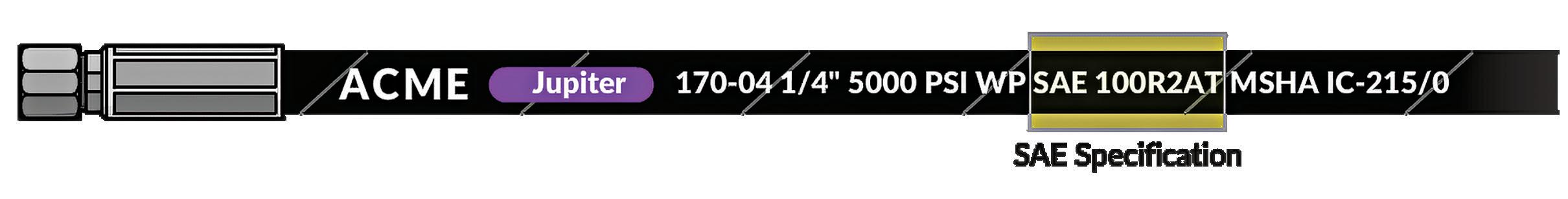
What are the common hydraulic hose specification standards?
WE TEND TO WALK THROUGH LIFE enjoying what seems to be infinite consumer and commercial goods without consideration for the vast technological achievements that led to their existence. Every new technology rides on the shoulders of a previous advancement in either materials, construction, technology, or process. Very little in our high-tech world is truly a groundbreaking, stand-alone achievement.
What’s even less considered, and even in our specialized hydraulic industry, is all the thought and energy given to specification standards. Just in fluid power alone, there are thousands of the brightest minds on committees at ISO, NFPA, SAE, ASME,
DIN, CSA, and many others. Mainly acting behind the curtain, these associations have shaped everything we do in fluid power and with good cause. Imagine if all our hydraulic hoses, valves, pumps, and cylinders had zero compatibility.
Additionally, we have the peace of mind installing and operating our hydraulic components because these associations have put their stamp on the various safety standards applied to each. By mandating a minimum level of performance and outlining the testing criteria, we can compare different offerings within one manufacturer’s catalog with those of competitors and do so with confidence.
Hydraulic hose specification standards
provide us with such confidence, and you need to be aware of a couple of things. The most common in North America is the SAE J517, which provides general, dimensional and performance specifications for the most common hoses used in hydraulic systems on mobile and stationary equipment.
You’ll have seen the most common J517 standards, such as 100R1 and 100R2, which define one- and two-wire general-purpose hydraulic hoses so popular in North America. Although the exact materials and manufacturing technique leaves a small margin for creativity, the standard ensures the final product adheres to pressure ratings, bend radius and temperature range, to name a few.
In most cases, the maximum working pressure is based on some safety factors of what’s achieved through proof and burst pressure. Proof pressure is the minimum pressure before permanent fatigue occurs and is double the hose’s working pressure. Burst pressure is self-explanatory and is no less than four times working pressure. In reality, your hose will likely perform
example, 100R7 is a non-conductive design for use around utilities to reduce the likelihood of electrocution, while 100R17 is quickly taking over as the do-everythingwell solution. 100R17 offers a wide range of sizes that meet 3,000 psi working pressure requirements regardless of hose diameter.
Rather than build standards around construction style, the ISO 18752 standards clas-
the pressure requirements across the board regardless of diameter. A 2-in. hose must be rated for 3,000 psi just as confidently as a ¼ in. hose, and to do so, the construction doesn’t have to be precisely the same.
The SAE J517 has newer standards following this philosophy, and you’ll see that 100R13, 100R15, 100R17 and 100R19 all offer across-the-board pressure ratings. Ulti-
well beyond these ratings rather than walk a tightrope of failure.
There are currently 19 classification standards for J517, although some are discontinued, and the popularity of others outweighs the sales of more specialized designs. For
sify based on a hydraulic system's required pressure and flow. After initial classification, hoses are further classified by their resistance to pressure spikes and refined by compactness, bend radius and temperature rat-
mately, the customer wants performance and ease of selection, so choosing three different hoses to suit one machine can be confusing. Why use 100R1, 100R2 and 100R12 on a single machine to suit different
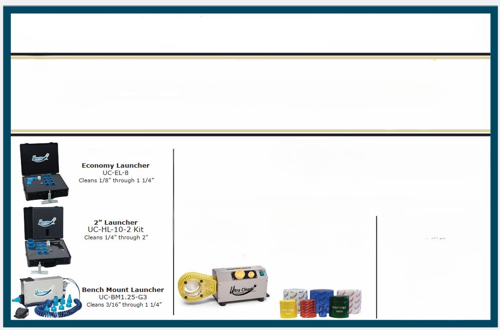
Ensure Peak Performance with Clean Hose Assemblies!
Clean Seal Systems
Only 19 capsule sizes needed for all assemblies. Seal straight or elbow couplings shorter capsules available for angled/elbow (45° and 90°) fitting. Seal from 3/8 OD (10mm) through 3" OD (78mm).
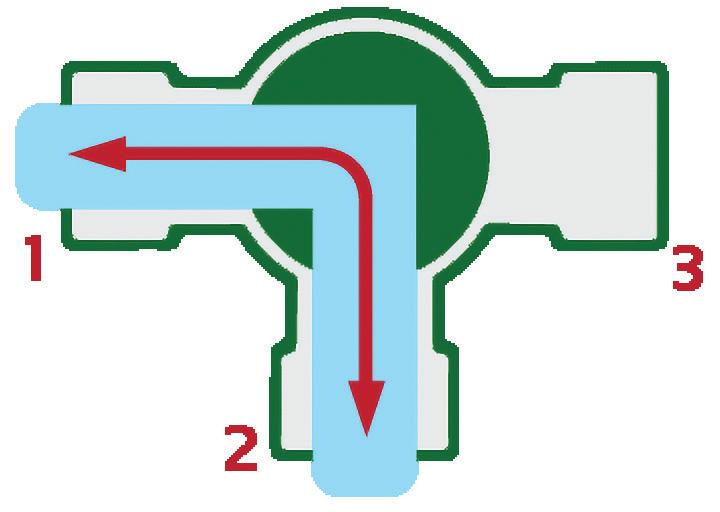
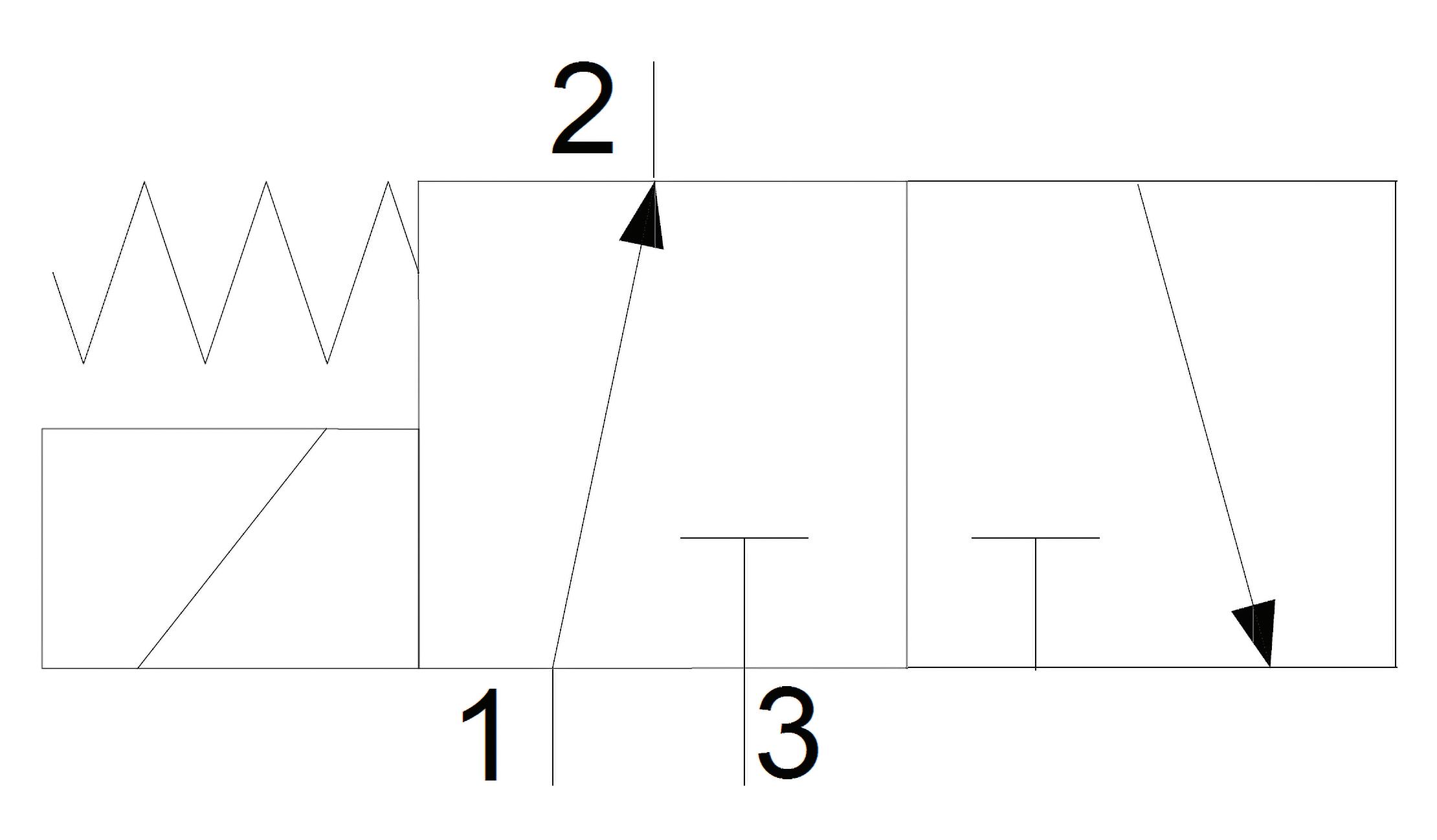
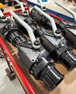
How do three-way valves work?
drilled with 90-degree holes to provide an L-shaped flow path (Figure 1). The image shows an open flow path from port 1 to port 2, where the fluid is free to flow bi-directionally. By rotating the lever, we can change the bi-directional flow path to ports 2 and 3. In some cases, manufacturers offer a sweet spot where turning the lever 45 degrees blocks flow entirely.
Functionally, a three-way valve is a practi-
The most common threeway valves in hydraulics are ball valves, cartridge valves and stackable solenoid valves (like ISO 4401 standard). Ball valves may come to mind for some when you think about a 3-way valve.
THREE-WAY VALVES, common and versatile tool in fluid power, demonstrate their precision by effectively diverting, selecting, or mixing three flow paths as the circuit requires. These valves, available in lever or solenoid actuation, are widely used for directional control. Their construction style varies, ensuring suitability for diverse applications. The three-way valve, a machined body with three ports, is a testament to their precision and adaptability.
The most common three-way valves in hydraulics are ball valves, cartridge valves and stackable solenoid valves (like ISO 4401 standard). Ball valves may come to mind for some when you think about a 3-way valve. They consist of a three-ported body, cast brass for low pressure use or machined steel for high pressure operation. Like any fluid power component, they are manufactured with any of the common fluid connection standards. Inside the 3-ported body is a ball cross-
lar to the one in Figure 2
What you see is a 3-way, 2-position valve with solenoid operation and spring offset. In the neutral position, fluid flows from port 1 to port 2, while port 3 remains blocked. When the solenoid activates, it pulls the right envelope to the left, where port 1 is now blocked while allowing free flow from port 2 to port 3. When the electrical current is removed from the coil, the spring bias
cal solution for diverting flow incoming from port 2 to either port 1 or port 3, as required. For instance, if you have a single hydraulic pump operating two entirely different downstream circuits, a three-way valve can efficiently manage the flow. Similarly, it can collect flow as required from either port 1 to 2, or from port 3 to 2. This versatility is particularly useful in applications such as selecting between reservoirs filled with different fluids or choosing between two pressure signals to be measured at port 2.
Solenoid-operated hydraulic valves, more succinctly called three-way, two-position valves, are also a common sight. Their physical manifestation takes many forms, such as cartridge valves, subplate-mounted valves, inline valves or custom configurations, but they can all be represented by symbols simi-
pushes the left envelope back again.
Such a valve may operate a single-acting cylinder, where turning on the pump extends the cylinder while switching the valve retracts it. Manufacturers produce many versions of this valve, so the ports may also flow bidirectionally through the ports. Other options may include flow between ports 1 and 3 or perhaps a second solenoid to allow 2-position detent functionality. There are other unique methods to take advantage of three-way valves, such as how two valves may replace a single 4-way, 3-position valve while offering unique advantages such as venting one cylinder port while the other remains closed. Threeway valves offer designers a versatile toolbox option and should be considered a solid option for unique circuits. FPW
FIGURE 1
FIGURE 2
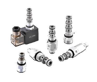
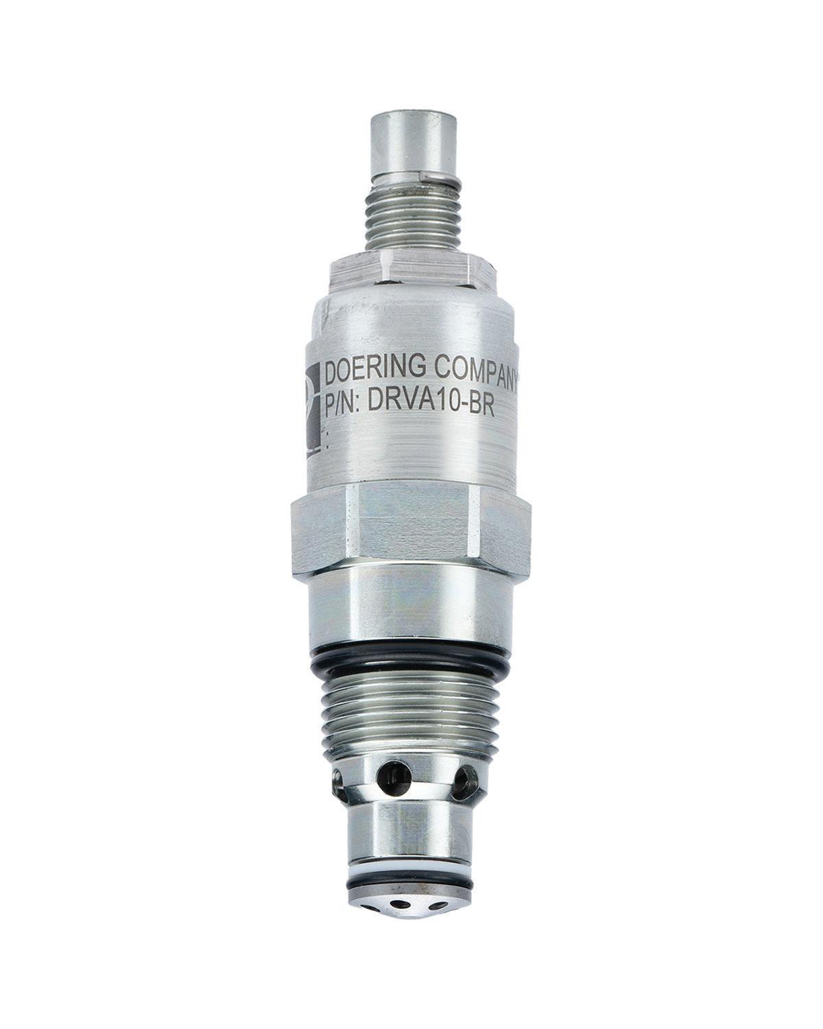
The DRVA is a screw-in, poppet type, direct-acting, cartridge-style hydraulic relief valve. For use as a pressure limiting device for common hydraulic circuit protection. This valve offers fast response to load changes in typical hydraulic circuits requiring low hysteresis, low pressure rise and low internal leakage.
Features:
• Hardened poppet and seat for long life and low leakage.
• Adjustable, fixed or tamper resistant adjuster.
• Compact size for minimal space requirements.
• Optional spring ranges.
• Industry common cavity.
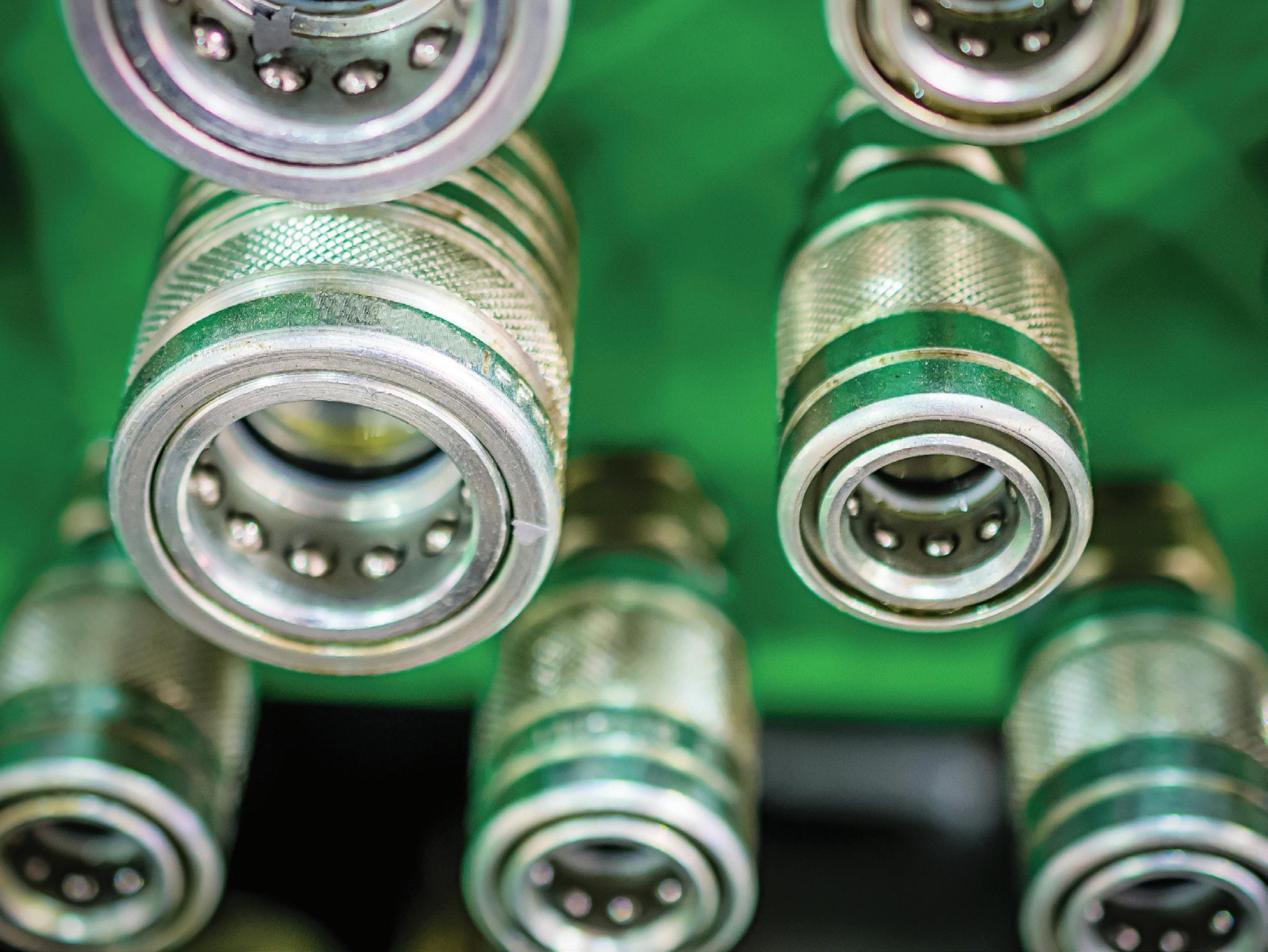
Design considerations for hydraulic couplers
HYDRAULIC QUICK COUPLINGS
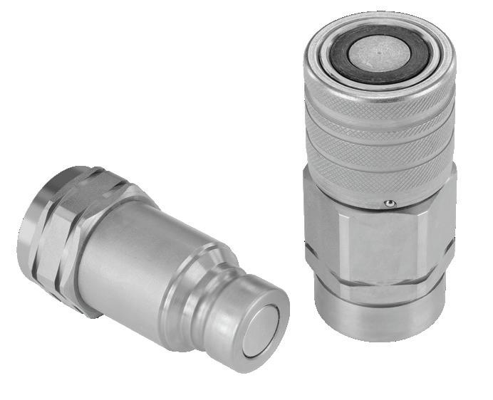
are as crucial to the design of a machine as are the pumps, valves and actuators. They provide users with the ability to rapidly connect and disconnect hydraulic hoses to machines or other sections of plumbing for machine attachments. These couplers provide a secure and leak-free connection, allowing for seamless fluid transfer in hydraulic systems. Also called quick-connects or quick disconnects, these fittings allow fluid to flow when the male and female sides are locked together. Conversely, when disconnected, the quick couplings prevent fluid leakage by using check valves to block exiting fluid.
Typically made of durable materials like steel or brass, hydraulic quick couplers consist of two mating halves: a male and a female coupler. The male coupler features a protruding nipple with a check valve to prevent leakage when disconnected. The female coupler has a corresponding socket
with internal seals and locking mechanisms. When the two halves are brought together, they form a tight seal that prevents hydraulic fluid from escaping.
There are two primary construction styles for hydraulic quick couplings. The check valve style system uses either balls or poppets to block flow from exiting the fitting. When connected, the balls or poppets push against each other, lifting both off their seats to allow flow through the connection.
Flat face couplers employ a more sophisticated interface that, when joined, will push face sections into each other, opening a large flow path through them both.
Thread-to-connect couplers employ male threads on the nipple portion, and when inserted and tightened into the female coupler, squeeze together to open both check valves. Thread-to-connect couplers offer a very high-pressure rating while offering very little flow in return.
Quick couplings should be sized based on their flow capacity. It’s a mistake to size couplings relative to the thread size on the hose or fitting to which the coupling attaches. For example, 3/8 in. quick couplings may only flow 4 gpm at 20 psi of backpressure, while the hose itself may flow double that amount.
It’s perfectly okay to use bushings to reduce the larger thread on the coupler down to the size of your plumbing. If your hose thread is larger than your coupling thread, your coupling is likely undersized.
Flat face couplers offer a more significant flow path with reduced pressure drop. Their interlocking sleeves open an extensive crosssection than poppet-style couplings. The poppets or ball-checks of the latter interfere with the flow path, creating pressure drop.
Just like many (but not all) hydraulic components, you get what you pay for. A set of ball-check couplings purchased from a local tractor parts store will offer little in common with the premium flat face couplers.
Inexpensive couplings will corrode more quickly, which is a problem with mobile applications. As previously mentioned, the flow rate will suffer using ball-check couplings, forcing you to oversize the set and pay more regardless. Cheap couplings will also leak more readily, all the while offering little in the way of smooth connection and disconnection. Finally, the poppet style loses oil every time you disconnect it and is also prone to collecting contamination in the female end’s open face.
Premium flat face couplings offer corrosion-resistant parts that are precisionmachined to offer the smoothest, most reliable connection. As discussed, their large flow path offers lower pressure drop, so you’re benefiting from using a more appropriately sized set. Finally, most flat face couplings offer a twist lock that prevents accidental disconnection should an object hit the sleeve. FPW
Solutions Under Pressure
Check
Flow
Needle
Flanges & Adapters
Bar & Custom Manifolds
Pressure Gauges & Snubbers
SSW Power Unit Systems
Transfer Pumps
Industries Served:
• Oil & Gas
• Industrial Hydraulics
• Mining
• Forestry
• Chemical & General Processing Plants
• Medical
• Aerospace
• Factories
• Mobile Equipment
• Defense
• Machine Tool
• Testing Equipment
• Ocean Depth Technology
• Automotive
• Food Processing
• Agriculture
• Industrial
• Aviation
• Petrochemical
•
7 reasons why you should use drawwire encoders
A DRAW-WIRE ENCODER (also known as a cable extension transducer or string potentiometer) is ideal for measuring linear displacement (distance) in a variety of applications where precise position is required. A draw-wire encoder uses a wire or cable wound around a spool, connected to a rotary encoder or potentiometer housed in a protective casing. A spring mechanism ensures the cable stays in constant tension, even during rapid retraction.
2. They are compact and require minimal mounting space, making them suitable for applications where space is restricted, especially at the attachment end where a simple eyelet is used.
3. The draw-wire encoder isn’t relegated to a single axis of motion since the wire can follow curved or nonlinear paths; they are useful when the measurement path is not straight or direct. The cable can bend around idler pullies as well, so even
LDTs installed into cylinders, for example, can be quite expensive even before the provisions are made in the cylinder to accommodate the sensor. The rod must be gun-drilled and the cap machined to accept the electronics and connection point.
7. Many models are rugged enough for industrial settings, with resistance to dust, dirt, and moisture. If you have a particular level of weather or washdown pro-
It’s no surprise [draw-wire encoders] are used on various components of automation to track linear mechanical movement in machinery.
The spool’s rotation converts into an electrical signal by the rotary encoder, which outputs position data in either analog or digital format. The housing protects the mechanism and has some type of bracket to help secure the encoder to the machine. With such a simple and effective design, there are many reasons you should use a draw-wire encoder.
1. Draw-wire encoders are excellent for measuring long distances, often ranging from just inches to many yards. The encoder itself has no limitations, so the measuring length is only limited by the reel mechanism.
the mounting point of the reel does not need to be along the same axis as the measured end.
4. They can be mounted in various orientations and are easy to integrate into existing systems. If you find out later that you want to accurately measure the cylinder stroke length, the draw-wire encoder can be added to the machine with some simple brackets rather than a complex installation inside the cylinder itself.
5. They are suitable for measuring the movement of objects like platforms, doors, or machinery components, where both position and velocity must be relayed back to the PLC or machine controller.
6. Compared to other types of linear measurement devices, they are often more economical for long-range applications.
tection you’re looking for; chances are a manufacturer will have a solution for you. You can find draw-wire encoders on many machines and applications. They’re perfect for hydraulic cylinders to monitor the position and velocity of both extension and retraction travel. They’re popular on construction equipment, such as booms and platforms with very long extension lengths. And it’s no surprise these are used on various components of automation to track linear mechanical movement in machinery. Material handling and positioning applications are perfect for draw-wire encoders, as are test machines requiring position measurements, such as for tensile strength. If precision, robustness, and compact installation for long linear measurements are key factors, a draw-wire encoder is a fantastic choice. FPW
When to use a digital pressure gauge
BOTTOM MOUNT PRESSURE GAUGES are accurate and reliable, but sometimes you ask for more of your pressure monitoring device. Analog pressure gauges can sometimes be difficult to read and don’t have the same accuracy levels digital do.
Good digital pressure gauges offer accuracy down to 0.025%. Accurate observation of suction or case pressure, in some cases, may help when you can measure and observe with precision. Even a mediocre digital gauge with 0.5% accuracy offers plenty of confidence that what you see in a glance is what the pressure is.
Although analog gauges may come available with sliding indicators that mark the desired minimum or maximum pressure, you must still watch the gauge when such
pressure extremes occur. However, digital pressure gauges may use data logging to save the minimum and maximum value and then reset them easily to restart a cycle. Digital pressure gauges come equipped with backlights, and a press of a button will light up the LCD screen to make readings effortless. Analog gauges, on the other hand, may require extra lighting to read properly.
PT SERIES Fixed Range Pressure Transmitter Por
tfolio
Additionally, a wireless transceiver sends readings to your PC, which offers the advantage of evaluation and analysis through spreadsheets and charts, making them a valuable predictive maintenance tool.
Because analog gauges use markings printed on their face, you're limited to the units on any given gauge, and if you're lucky, you'll get dual units such as psi and bar. On the other hand, a digital gauge may offer as many unit options as are in common use, such as psi, bar, MPa, or even kg/m², depending on your geographic market.
Finally, the more optioned digital units are available with switching outputs. And although more expensive than analog gauges, digital gauges continue to drop in price just like all electronics. FPW
Understanding air flow and FRLs
PNEUMATIC SYSTEMS power industrial machinery and equipment, reliably and efficiently. The Filter-Regulator-Lubricator (frl) is vital in maintaining optimal air quality and pressure within these systems. However, when selecting an FRL, one must not overlook the significance of understanding FRL air flow characteristics, which is more complex by nature than more simple components. By comprehending and considering airflow, one can make informed decisions to enhance system performance, reduce downtime, and extend equipment lifespan.
Airflow is critical in determining the efficiency of pneumatic systems, as any pressure created to overcome restrictions is forever lost as heat. An FRL matching the system's required flow rate ensures that the equipment and actuators receive an adequate supply of clean, pressure-regulated air. Insufficient airflow can lead to decreased system performance, slower actuation times, and compromised productivity. On the other hand, oversized FRLs may result in unnecessary energy consumption, increasing both capital and operational costs. Understanding air flow helps strike the right balance, opti-
mizing efficiency and maximizing output. Regulating air pressure is crucial to safe and reliable operation of pneumatic systems. Insufficient pressure control can result in erratic actuation, unstable operation, and potential damage to components. Conversely, excessive pressure can cause leaks, premature wear, and even equipment failure. FRLs’ flow characteristics are described in two ways — flow rate and pressure drop.
The flow rate through an FRL is dictated partially by the size of the filter, regulator and lubricator, as well as the construction style of each component and the pressure setting of the regulator. The filter media construction and micron rating affect the backpressure across the filter, with deep pleated designs down to 0.01 micron tending to resist flow more than inexpensive 5-micron filters. Still, it's easy to oversize your assembly rather than sacrifice filtration quality.
The lubricator reduces flow the least in the FRL and is an oil reservoir using the Bernoulli principle to atomize lubricating fluid into the air stream. The flow reduces slightly as it passes through the venturi, where the increase in flow rate reduces localized pressure, thereby pulling oil up the capillary tube where it's introduced into the air stream.
The regulator influences airflow the most through an FRL and, by its very nature, may restrict flow to subsequently reduce pressure. The essential function of a regulator inherently restricts airflow to reduce downstream pressure. Using poppets, pistons or diaphragms, the regulator's spring and its preload control the force required to open the valve and allow flow to occur. Users may adjust the spring tension to adjust the preload to increase the pressure that prevents the restrictive element from closing as easily. The regulator seamlessly balances the restriction with the outlet pressure to smoothly control pressure at the desired setting, opening the valve to increase pressure or closing it to reduce pressure.
Regulators have an operating range best suited to their design, and any pressure and flow used outside that range results in either weak pressure control with unstable flow or a locked regulator with no flow. Downstream pressure must remain well below the regulator set pressure, or the unit may lock up and allow no flow at all. Conversely, when the flow is high while pressure is low, energy is wasted to pressure drop. The higher you set your regulator, the less it will flow. As previously mentioned, the regulator restricts flow to reduce pressure, so trying to regulate pressure in the upper reaches of the design range may restrict flow to an unacceptable degree. Be sure to select a regulator that flows well in the upper-pressure range, should you need it.
The above descriptions are simplified because regulator design is surprisingly varied. Singe stage regulators work well with stable, low-pressure regulated machines and tools. However, if your plant's air usage varies widely or machine demand is not stable and constant, a two-stage regulator provides a superior choice. In some cases, regulators are also available with the pressure-compensated option that helps maintain stable flow despite fluctuations from inlet or downstream pressure. FPW
9 tips to prevent air hose leaks
AIR HOSES ARE VITAL for many pneumatics-heavy industries, serving as lifelines transporting air to power machinery and tools. However, leakage is a common and frustrating issue that often arises in many pneumatic distribution systems. Leaks hinder efficiency and lead to unnecessary energy waste and increased operational costs. Thankfully, preventing air hose leaks is an attainable goal through a combination of proper maintenance, careful usage and the right equipment. Follow these nine tips to prevent air hose leaks:
1. Select quality hoses:
The foundation of preventing air hose leaks lies in choosing high-quality hoses from reputable manufacturers. Select only hoses manufactured from durable materials that are resistant to wear, suit your application and are suitable for the ambient and oper-
ational temperatures of your plant and machine. Reinforced rubber or hybrid polymer hoses are recommended, as they are less prone to kinks and punctures while offering excellent flexibility and pressureholding capacity.
2. Proper storage and handling:
Improper storage and handling may significantly contribute to air hose leaks should the hose be damaged from falling objects or long-term UV exposure. Store hoses indoors, away from direct sunlight, chemicals, and extreme temperatures. When a loose hose is not in use, coil the hose neatly, preferably using hose reels, to avoid twists and kinks that can weaken the hose structure over time.
3. Regular inspections:
Frequent visual inspections are crucial in catching potential leaks early. Look for signs
of wear, cracks, abrasions, or bulges along the hose's length. Additionally, pay close attention to the hose's connections, including fittings, couplings, and connectors, as these are common leak-prone areas where the flexible hose meets the rigid metal.
4. Secure fittings and couplings: Properly installed fittings and couplings are essential for preventing air leaks. Ensure that connections are tight and secure, but avoid overtightening, which can damage the hose or fitting threads, especially when softer material is used for the fittings and adapters (such as brass). Use thread sealant or Teflon tape on threaded connections to create an effective seal. Also, remember that NPT should be considered a "one and done" thread connection and is not meant for repeated or frequent installation and removal.
5. Minimize abrasion:
Air hoses are often subjected to friction and abrasion against surfaces and objects, weakening the material and leading to leaks. Use protective covers or sleeves to shield the hose from abrasive surfaces whenever possible. This is particularly important in environments where hoses may come into contact with rough edges or moving parts.
6. Maintain proper pressure:
Operating air hoses within their recommended pressure range is vital to prevent leaks, as exceeding the hose's maximum pressure can lead to stress and ruptures, causing leaks or even hose bursts. Implement pressure regulators and pressure gauges to ensure the air pressure remains within safe limits.
7. Address kinks and bends: Kinks and sharp bends not only impede
airflow but also weaken the hose structure, as the kink creates internal stress in the polymer. Avoid bending the hose at acute angles and minimize kinks to prevent potential leaks. If you notice a kink, carefully straighten the hose to restore its integrity, but if your hose maintains a permanent deformation from a long-standing kink, replace the hose before a leak inevitably occurs.
8. Replace damaged hoses promptly:
No matter how well you maintain your air hoses, no pneumatic system enjoys infinite plumbing life. If you discover significant damage or wear during inspections, do not hesitate to replace the hose because prompt replacement can prevent unexpected leaks and reduce the risk of operational downtime. Pneumatic hoses are inexpensive compared to the loss of revenue when machines are not producing product.
9. Train users:
Proper training for individuals who operate pneumatic tools and machinery is essential to preventing air hose leaks. It is also crucial to ensure that your facilities' management team understands the importance of careful handling, correct storage, and regular maintenance. Educated users are more likely to contribute to the longevity and leakfree performance of your air hoses, especially when they understand the repercussions of a failure.
Preventing air hose leaks demands a proactive approach that encompasses the selection of high-quality hoses, proper storage, regular inspections, and careful usage. By adhering to these practices and taking swift action when damage is identified, you can ensure that your air hoses remain efficient and leak-free, contributing to a more productive and cost-effective operational environment. FPW
5 reasons your pneumatic cylinder isn’t working
PNEUMATIC CYLINDERS ARE ESSENTIAL
in various industrial applications, providing the mechanical force needed to move loads, automate equipment, and perform countless other tasks. However, pneumatic cylinders encounter issues that impede their performance like other machine components. When your pneumatic cylinder isn't working as expected, it can lead to downtime, reduced efficiency, and increased maintenance costs. What's worse than your malfunctioning cylinder is not knowing why it won't function. Here are five common reasons your pneumatic cylinder isn't working.
1. Air leakage:
If you can hear hissing from one or more places on your cylinder, or if it moves sluggishly or not at all, your air cylinder may be leaking. For example, if you find your cylinder isn't holding its position, it's likely because air is leaking past the piston seals. But also, these leaks can occur at various points, including the cylinder end seals, cushion seals or at its ports. To remedy this problem, you'll need to identify and fix the source of the leakage, which often involves replacing worn seals or tightening connections.
2. Lack of lubrication:
Many pneumatic cylinders require proper lubrication to function smoothly. Without adequate lubrication, the internal components can experience increased friction, reducing efficiency, while creating static fric-
tion and potential damage. Regularly check and maintain the lubricator to ensure your cylinder operates smoothly. Additionally, use the recommended lubricants or oils to prevent seal compatibility issues.
3. Cylinder misalignment:
Pneumatic cylinders must be properly aligned with their load in an axial plane. Misalignment can cause uneven wear, increased friction, or even all-out breakage, so make sure your cylinder is correctly positioned along its force vector and that it operates within its specified load and speed limits. If necessary, realign the cylinder or install spherical bearings or alignment couplers.
4.
Contaminants and impurities:
Dust, dirt, and other contaminants in the air supply can wreak havoc on pneumatic cylinders. These particles can enter the cylinder and damage seals, pistons, and other internal components. Regularly inspect and service the air supply system (including the compressor) and maintain filters to prevent
contaminants from entering the cylinder. As with hydraulics, cleanliness is one of the best practices to improve reliability.
5.
Inadequate pressure or flow:
If your pneumatic cylinder seems sluggish or fails to provide the necessary force, it may be due to insufficient pressure or airflow. Check that the air compressor and regulator settings match the cylinder’s requirements and aren’t below specification. Adjust the pressure as needed to ensure the cylinder operates within its specified parameters or replace malfunctioning regulators. Additionally, inspect the air supply lines for obstructions that may limit airflow.
Like many fluid power components, pneumatic cylinders have finite lifespans, and understanding when to replace them is crucial. Here's a bonus tip:
6. Age and usage history:
Consider your pneumatic cylinder’s age and usage history, as older cylinders or those subjected to heavy and continuous use are more prone to wear and failure. Keeping records of installation dates, service, and usage can help you anticipate when a replacement or preventive maintenance is necessary.
Maintaining the reliability and performance of your pneumatic cylinder is vital for the efficiency of your industrial operations. By addressing issues promptly, conducting regular inspections, and following proper maintenance practices, you can avoid costly breakdowns and expensive downtime. If you're uncertain about the condition of your pneumatic cylinder, it's advisable to consult with a qualified pneumatic technician or engineer who can conduct a thorough inspection and provide guidance on whether it's time for a replacement. Staying proactive is critical to keeping your pneumatic cylinders in optimal working condition, ensuring smooth and efficient industrial processes. FPW
WE HAVEN’T SWITCHED A THING.
We make more products than ever, including transducers, cylinders and switches of all types. But our reliable temperature switches are still the perfect fit for all kinds of industrial applications. Our TT, TW, TD, TF and TS switches are available in a wide range of configurations, and are all 100% tested for accuracy.
T: Bi-metal immersion switch for low voltage/low current applications. Compact in size with a variety of probe lengths. Electrical and threaded media connections. Tight temperature differential. IP67 rated. mA-6 amp contacts available.
• TW: Bi-metal snap action immersion switch for higher temperatures. Compact in size with a variety of probe lengths. Electrical and threaded media connections. Wide temperature differential (30%). IP67 rated. 10 amp.
• TD: Snap disc design for high reliability with shock and vibration. A variety of electrical options are available. mA-10 amp contacts available.
• TF: Snap action thermostat switch for lower temperatures up to 100,000 cycles. mA-15 amp switch with a variety of electrical options. IP67 rated.
• TS: NEW temperature sender (NTC and RTD resistance). Resistance range -40 to 302 degrees F. Compact in size with a variety of probe lengths. Electrical and threaded media connections. Quick response time. IP67 rated.
Get your switch on at nasonptc.com/switches
What pneumatic valves should you select for automation systems?
THERE ARE A LOT OF PNEUMATIC directional valve options on the market. There are the big players in the game who take up half the market under only a couple of brand names, but the remaining half of the industry contains hundreds of players with myriad options. When selecting valves for automation, there is a lot to choose from, so it helps to understand the basics as well as the common threads that tie them all together.
In high-demand, high-volume production factories, the number one criterion for a valve system is performance. Performance can entail many things for a pneumatic valve: flow rate, response time, service life and Fieldbus connectivity, for example. Each of these considerations is important to the engineer or designer selecting a valve package for their machine.
The Holy Grail of pneumatic valve technology is making a small valve flow big, and manufacturers are constantly looking for ways to improve their valves’ flow rates.
In high-demand, highvolume production factories, the number one criterion for a valve system is performance.
You may find it listed by actual flow rate expressed in liters/min (or scfm), but also Cv or even described by how quickly a given bore of cylinder will travel. Cv is an odd unit described as gallons per minute of water at 60°F at 1 psi pressure drop, but what’s important is that more flow is better. Response time describes how quickly the valve can shift, and the upper echelon of products lists how their valves perform. Response time is important for automation functions working at blinding speeds, such as packaging machines, textile airjet looms and sorting machines. Although pneumatic valves are already quick, you can
expect high-performance versions to be 20-30% faster still.
Any high-volume production line will lose bags of money during machine downtime, so you can expect the big players to offer sensational claims of hundreds of millions of possible cycles over a valve’s lifetime. Whether such claims are smoke and mirrors or based on lab results, you won’t go wrong choosing one of the big players with solid reputations. Even if said valve fails, their valve systems often make the replacement of valve sections within a bank or manifold quite quick and easy, reducing any downtime to minutes rather than hours or days.
Fieldbus connectivity makes the identification of failed valves a breeze. There are a dizzying number of possible control systems, so expect the ease of automation that comes with your preferred method of serial transmission — DeviceNet, PROFIBUS, EtherNet/IP and every other combination of acronyms and contractions electronics engineers dreamed up because they thought they had the better mousetrap.
Fieldbus systems are important for automation because they ease the installation, operation and diagnostic functions of a control system. By running a single cable to a valve bank, you reduce wiring complexity, ease the integration of subsequent valves, improve diagnostic capability, and reduce cost.
Automation through pneumatics has come a long way since the days of cam and roller lever days when dozens of sequentially activated valves were coordinated to achieve complex functions. It’s never been cheaper and easier to automate machinery, and with the proper selection of pneumatic valves, you can achieve previously unmatched performance as well.