Acoustic Tuning
acoustically tuned concrete system
Architectural Association
Emergent Technologies and Design Masters of Architecture Thesis 2011-2012
Nicolas Entierre Leguina Sherwood WangAcknowledgements
Thank you to our friends and families.
Table of Contents
Introduction
Abstract
Thesis Statement Domain
Architectural Application Programme Urban Logic Architectural Acoustics
Fabrication Formwork
Acoustic Spacers Jump-Form System
Digital Integration
Perforation Catalogue
Perforation Assignment
Conclusions and Evaluation
References/Appendices

Research Introduction
The research within this document attemptsing elastic materials to create an acous-


Abstract:
Traditional techniques of jump-form concrete casting restrict variability of forms that are able to be produced due to the highly specific forms that are commonplace in rigid moulds. The possibilities of variation within a elastically flexible rubber formwork system will be investigated for a new concrete casting method, which also is durable for repetitive casts. Coupled with the flexible formwork research is the tuning of the system based on acoustic response, through the control of a perforation gradient and overall geometries. These tools are used to facilitate the design of an acoustic park, where individual stages create a complex of acoustic fields.
Keywords:Concretecasting,jump-formcasting, acousticsurfaces,acousticperforations,flexible formwork,elasticformwork,modularformwork,reusableformwork


Thesis Statement:
The influence of concrete construction has spread globally. The reliance of the building industry on concrete is overwhelming. The utilization of the components of concrete is only surpassed by one other global resource, water. The base components of modern concrete (sand, aggregates, and Portland cement) can be found with relative abundance throughout the globe.
There is one particularity about concrete construction that is unlike any other building technology, the symbiotic relationship of concrete to formwork. Ancient Roman concrete construction utilized the cavity within hollow masonry walls in order to fill with concrete. Current practices involve many different formwork potentials: modular formwork, prefabricated sections, and climbing formwork systems. In all of these methods, there is significant efforts in the design and process of creating concrete formwork. In
most systems, however, there is difficulty in creating variations of forms without increasing the quantity of formwork.
The research involved within this document addresses an alternative formwork system which is reusable while also allowing for a wide variety of possibilities.


Domain:
Alternative materials for concrete formwork has gained more prominence recently as synthetics and composites are becoming more economically viable in architectural construction. The research of C.A.S.T and Alan Chandler utilize fabrics in a way where the bulging of the fabric under hydrostatic pressure is exploited for their relation to structural performance. In both systems, geo-fabrics are used to create doubly-curved pre-fabricated panel.
Architectural acoustics research is being investigated through parametric tools in several areas. Acoustically sensitive modular units were designed such that by tuning individual units.


Elastic Formwork
interesting with this aspect is that depending on the


 Synthetic Rubber


Parametric Acoustics
other, the design is an input and panels are not going to
Investigations into parametricism and acoustics have


Concrete Systems
The research in this document investigates areas within in


Programatic Acoustical Needs:
Embedding acoustic requirement and characteristic information into every programatic node in order to generate and implementable catalogue
Urban Evaluation of Proposed Network:
Generation and evaluation of di erent path networks according to a ttness criteria and a connectivity integration algorithm
Nodal Rules
The programatic nodes are assigned certain rules to move within the selected site, the algorithm runs and generates di erent soundscapes
Topographic Generation:
All the acoustic requirements and charactereristics are translated to generate a topography which minimizes sound interference
Urban Scale
Utilizing the topography to create acoustic wells in which varying programmatic performances are accomodated and interrelated
FESTIVALS
The Mill Hill Music
Hard Rock Calling
City of London
Wireless Festival
The Big Chill Festival
The 1234 Shoreditch
iTunes Festival
The Sundae Festival
The High Voltage
The Ealing Summer
The BBC Proms
The Lovebox
The Vintage
The Field Day
The Apple Cart
The Little London Fields
The South West Four
VENUES
Mill Hill
Hyde Park
London’s ornate churches
Hyde Park
Eastnor Castle
Shoreditch park
The Roundhouse art centre
Clapham Common
Victoria Park, London
Walpole Park, Acton Park, Royal Albert Hall
Victoria Park
Southbank
Victoria Park
Victoria Park
London elds
Clapham Common
CAPACITY/DAY
80-120
40.000-50.000
10.000-15.000
30.000-50.000
20.000-35.000
2.500-3.000
6.000-9.000
15.000-18.000
6.000-8.000
14.000-16.000
3.000-5.000
15.000-16.000
12.000-20.000
9.000-12.000
8.000-9.000
2.000-5.000
9.000-11.000
Title
London is one of Europe’s cultural centres, It is one of Europe’s cities to cater more musical events within its metropolitan area, this being due to the size of the city population and to the urban configuration, being based on the concept of a garden city entails a great amount of open green spaces with a great variation of size. This is perfect in order to be able to hold venues within London that can range from 50000 people (Wireless Festival at Hyde park) to merely 2000 people (The Little London Fields Festival, at London fields).
The great variation in size and location of these festivals enables us to test the proposed system in different situations with different parameters and experiment with the adequacy of the system to handle such an amount of variables and thus gives the opportunity to delimitar the threshold that the system can Handle.
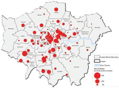

Outdoor activities that require a certain level of acoustic performance are extremely common in London, open air theatre, music festivals, and a variety of concerts are offered annually across the city. The drawback from this activities is that they are seasonal an use temporary architecture. Our system is thought to be permanent. It is clear that a continuous function is needed to be able to act as a substrate for the acoustic nodes.
There is a vast network of markets in London composed of 163 markets within the city, which have a clear a contribution to the London economy as well as the wider social benefits markets bring, as explained in the paper “ London’s Retail Street Markets - Draft Final Report “by Regeneris Consulting.
It is clear that market make a great contribution to the vitality of the many town centres London has, the afore-


mentioned study suggest that “ number of individual existing town centres would lose out if their markets were to close. A large minority (42%) of customers surveyed for this research said they would not visit the town centre if the market was not there.”
It seem clear that a market is a good solution to increase human flow on the area and provide a constant use. As seen on the diagrams, the area of intervention of the system caters big market both by number of pitches and days but also has barely no decaying markets while holding some of the new markets. The conclusion can be drawn that a market would be a successful program in this area.
This will make the system hold two main have a main programmatic division. Acoustically active program, the festival and everything associated with it. Non acoustic active program, the market and all the uses that accompany it.


In order for the design to meet the specific acoustic needs of the various these activities should be divided into groups with common acoustic characteristics. Sound has very specific characteristics, even when dealing with sounds produced by the same type of instruments one can see that the range of frequencies and intensities vary. A division according to the type of instruments could be made in order for the design to respond to those distinct needs, but this would generate an extremely restrictive programmatic division . For this reasons it was decided that the division into categories should be done by scale(hence sound intensity) and by a broader set of common acoustic characteristics, in this case speech and music where chosen since they are extremely appropriate for London due to the set of activities that the city holds.
A programmatic catalogue was developed in order to set the different activities in the site and to build the acoustical specific surfaces to accordingly to each activities. The catalogue was developed as previously mentioned using sound type and intensity and having in mind what activities are already present and promoted in London
Music Activities, Scale 1: Concerts sdddddddddddddddddddddddddddddddddddddddddd sdffffffffff ffffffffffffffffffff sdfggggggggggggg sdfggggggggggggggg gggggggggggggggggggggggggggg sagddddddd saggggggggggggg sagdegr ehg d a sdddddddddddddddddddddddddddddddddddd dddddd sdffffffffffffffffffffffffffffff sdfggggggggggggg sdfggggggggggggggggggggggggggggggggggggggggggg sagddddddd saggggggggggggg sagdegr ehg d a sddd dddddddddddddddd ddddddddddddddddddddddd sdffffffffffffffffffffffffffffff sdfggggggggggggg sdfgggggggggggggggggggggggggggggggggggggg ggggg sagddddddd saggggggggggggg sagdegr ehg d a
Spoken activity, Scale 1: Open air theatre: It is undeniable that London is the theatre capital of the World and despite the not so adequate weather for outdoor theatre it is the European city that holds more outdoor theatre venues. Being held in sites such as Regents park, the famous Shakespeare’s Globe, or the scoop next to the city hall.
The scale of the program will be defined by its capacity. At present the outdoor theatres range in capacity, going from minimum capacities of 800 up to a to a total of 1500


in the case of the globe. Outdoor theatres in the classical world could gather up to 12000 people but in modern times they have become even greater, like the biggest outdoor theatre in Europe whichis set in Scarborough and can hold up to 8000 people.
Spoken activity, Scale 2: Speakers
The right to hold speeches in public areas has been ingrained in the British culture since the 1850’s, and specifically in London. In 1872 the parks regulation acts was passed delegating the control of public meetings to park authorities instead of the central government. This in effect set the grounds for speakers corners to be allowed . Historically there were a number of areas designated as Speakers’ Corners in parks in London (e.g., Finsbury Park, Clapham Common, Kennington Park and Victoria Park), the most important of which became the one in Hyde park. Since that time, it has become a traditional site for public speeches and debate, as well as the main site of protest and assembly in Britain.
Music Activities , Scale 2: Busking London is one of the cities in Europe that has regulated
street busking through the London Underground busking scheme that now manages what was once an illegal activity . Nearly 400 buskers entertain the travelling public in tube stations throughout the city every week, London Underground runs up to 3,000 weekly time slots which licensed buskers can sign up for. This in effect means that this street performers, most o them musicians have to maintain a certain minimum quality to perform. Busking is not only regulated but encouraged, the buskers can compete in a mayor event once a year called the Busk off, where they compete in assigned busking spots and then the top ten are chosen to compete amongst each other in a summer music festival organised by The Rhythm of London.

In order for the design to meet the specific acoustic needs of the various these activities should be divided into groups with common acoustic characteristics. Sound has very specific characteristics, even when dealing with sounds produced by the same type of instruments one can see that the range of frequencies and intensities vary. A division according to the type of instruments could be made in order for the design to respond to those distinct needs, but this would generate an extremely restrictive programmatic division . For this reasons it was decided that the division into categories should be done by scale(hence sound intensity) and by a broader set of common acoustic characteristics, in this case speech and music where chosen since they are extremely appropriate for London due to the set of activities that the city holds.
A programmatic catalogue was developed in order to set the different activities in the site and to build the acoustical specific surfaces to accordingly to each activities. The catalogue was developed as previously mentioned using sound type and intensity and having in mind
what activities are already present and promoted in London
Spoken activity, Scale 1: Open air theatre: It is undeniable that London is the theatre capital of the World and despite the not so adequate weather for outdoor theatre it is the European city that holds more outdoor theatre venues. Being held in sites such as Regents park, the famous Shakespeare’s Globe, or the scoop next to the city hall.
Tnd busking scheme that now manages what was once an illegal activity . Nearly 400 buskers entertain the travelling public in tube stations throughout the city every week, London Underground runs up to 3,000 weekly time slots which licensed buskers can sign up for. This in effect means that this street performers, most o them musicians have to maintain a certain minimum quality to perform. Busking is not only regulated but encouraged, the buskers can compete in a mayor event once a year called the Busk off, where they compete in assigned busking spots and then the top ten are chosen to compete amongst each other in a

In order for the design to meet the specific acoustic needs of the various these activities should be divided into groups with common acoustic characteristics. Sound has very specific characteristics, even when dealing with sounds produced by the same type of instruments one can see that the range of frequencies and intensities vary. A division according to the type of instruments could be made in order for the design to respond to those distinct needs, but this would generate an extremely restrictive programmatic division . For this reasons it was decided that the division into categories should be done by scale(hence sound intensity) and by a broader set of common acoustic characteristics, in this case speech and music where chosen since they are extremely appropriate for London due to the set of activities that the city holds.
A programmatic catalogue was developed in order to set the different activities in the site and to build the acoustical specific surfaces to accordingly to each activities. The catalogue was developed as previously mentioned using sound type and intensity and having in mind what activities are already present and promoted in London
Spoken activity, Scale 1: Open air theatre:
It is undeniable that London is the theatre capital of the World and despite the not so adequate weather for outdoor theatre it is the European city that holds more outdoor theatre venues. Being held in sites such as Regents park, the famous Shakespeare’s Globe, or the scoop next to the city hall.
The scale of the program will be defined by its capacity. At present the outdoor theatres range in capacity, going from minimum capacities of 800 up to a to a total of 1500 in the case of the globe. Outdoor theatres in the classical world could gather up to 12000 people but in modern times they have become even greater, like the biggest outdoor theatre in Europe whichis set in Scarborough and can hold up to 8000 people.
Spoken activity, Scale 2: Speakers
The right to hold speeches in public areas has been ingrained in the British culture since the 1850’s, and specifically in London. In 1872 the parks regulation acts was

caption text passed delegating the control of public meetings to park authorities instead of the central government. This in effect set the grounds for speakers corners to be allowed . Historically there were a number of areas designated as Speakers’ Corners in parks in London (e.g., Finsbury Park, Clapham Common, Kennington Park and Victoria Park), the most important of which became the one in Hyde park. Since that time, it has become a traditional site for public speeches and debate, as well as the main site of protest and assembly in Britain.
Music Activities , Scale 2: Busking
London is one of the cities in Europe that has regulated street busking through the London Underground busking scheme that now manages what was once an illegal activity . Nearly 400 buskers entertain the travelling public in tube stations throughout the city every week, London Underground runs up to 3,000 weekly time slots which licensed buskers can sign up for. This in effect means that this street performers, most o them musicians have to maintain a certain minimum quality to perform. Busking is not only regulated but encouraged, the buskers can compete in a mayor event once a year called the Busk off, where
they compete in assigned busking spots and then the top ten are chosen to compete amongst each other in a summer music festival organised by The Rhythm of London.
In order for the design to meet the specific acoustic needs of the various these activities should be divided into groups with common acoustic characteristics. Sound has very specific characteristics, even when dealing with sounds produced by the same type of instruments one can see that the range of frequencies and intensities vary. A division according to the type of instruments could be made in order for the design to respond to those distinct needs, but this would generate an extremely restrictive programmatic division . For this reasons it was decided that the division into categories should be done by scale(hence sound intensity) and by a broader set of common acoustic characteristics, in this case speech and music where chosen since they are extremely appropriate for London due to the set of activities that the city holds.
A programmatic catalogue was developed in order to set the different activities in the site and to build the acoustical specific surfaces to accordingly to each activities. The catalogue was developed as previously mentioned using sound type and intensity and having in mind what activities are already present and promoted in London
Spoken activity, Scale 1: Open air theatre:
It is undeniable that London is the theatre capital of the World and despite the not so adequate weather for outdoor theatre it is the European city that holds more outdoor theatre venues. Being held in sites such as Regents park, the famous Shakespeare’s Globe, or the scoop next to the city hall.
The scale of the program will be defined by its capacity. At present the outdoor theatres range in capacity, going from minimum capacities of 800 up to a to a total of 1500 in the case of the globe. Outdoor theatres in the classical world could gather up to 12000 people but in modern times they have become even greater, like the biggest outdoor theatre in Europe whichis set in Scarborough and can hold up to 8000 people.
Spoken activity, Scale 2: Speakers
The right to hold speeches in public areas has been ingrained in the British culture since the 1850’s, and specifically in London. In 1872 the parks regulation acts was passed delegating the control of public meetings to park
For this type of massive outdoor theatre to have good acoustic, in other words for the intensity and speech intelligibility levels to be acceptable all over the audience, two approaches can be taken, the placing of sound systems to increase the sound intensity evenly through the seating area. This approach would obviously defeat the whole purpose of the design of acoustic shells. the other approach the use of a semicircular slope for the seating area to be placed on, in these case the capacity comes determined by the size of the slope. Due to Victoria park being a flat park and a relatively small capacity seemed more adequate. A total capacity of 1000 people was chosen to determine the scale of the open theatre nodes.
It may seem that this function has been outdated and is now more associated with eccentric people trying to get heard than anything else, but as it has been seen recently there is still a demand for such spaces. The protests that started off in developing countries have extended into the richer areas of the world, countries such as Spain and Greece have been holding public debates on the mayor squares of the mayor cities. It has become clear that there is a need for the people to be heard. People in the US and now the UK have been camping outside the economic centres of their respective capitals in order to be heard. It is clear that the demands for spaces where the people can gather and debate and try to have an impact on the way things are going has grown due to the economic crisis. People realised that the conventional approach following the paths the state organises for them to be heard fail miserable. A new bottom up system has emerged where people freely gather and self organised into protest groups that put together manifestos and try to implement a change from the bottom upwards.
For public debates to be held with no acoustic aid and in an orderly fashion where everyone can be heard the capac-
ity of such events must be maintained within a certain threshold, it is for this reason that we have chosen to set the scale of this type of node at a maximum of 30 people per node.
Busking as of now is not only regulated within the underground system it is not legal in the rest of London although if it’s not considered a nuisance it is in general allowed. Its seems therefore that the ampliation of the busking scheme into a greater area makes sense since the current space is limited and the demand from good Buskers is very high.
The scale that one deals with when talking about busking is not very great as of now since they are only allowed to perform in the tube and passengers rarely stop to listen to them. In our site stopping and taking a minute to enjoy the performance could be implemented due to its being held in a park, therefore the scale of the node could grow from its current size to an average of 20 people, this is extremely difficult to asses since the attendance is proportional to the quality of the busker, this is why the maximum threshold is set in 40 people since more should start to decrease the average quality of the sound experienced by the listeners.
Epudae atemo exceatur moditibusdae voluptas accatibus cum quam enitem reptatur suntiae et arition sequamus pero vel ipsapel endit, sit il ma abore pedi ut faccupt aesequias aut etur? Nat ipsant dit et, occusap icipiet mos sit modionsequo torum re volupita comnima gnimolore aditam exero is intem et eturit lam, sitionse assunda coribus eatibus restrumquis que poreptat facit fugia plab idic te none sum vernatus etur?
Ficae elignimenet eturibus dunt, ut rerchitatur sum nonet aut am, comniam ut perunti beatur, temquis sint. Vent pe ilibust voluptatem fuga. Roria volorit fugiasitint quam, sumque volorei cimus.
Isciatus ea aut essi bere dolorpo riberit quia dellatem ide quibus ellum aribust, et veliquia apiet ut ditem doluptibus, sa que magnis endest, conem ad quid et qui tem repelignias a dolendaes pos eium doluptature doloratatur, sum sequibus eribus.
Erum est, con cum aliquis quiantis apid quia dolorerit qui omniaerene none sequi quos volum estium que pres quide doluptae exero volorit adi con rehenih iligenduntum doles alibus que nateniam, quos quibus eatus ent doles re prepuda derspit, quidend icatum iumentio. Alique modi illuptiusdae vent mos sequi qui comnieniment volupti bustinis
conecum nonserum dollaceriae volore porepelenit eum sandit eosti consequos maiora sitati tem nonsectet voluptatem. Ut officiis que pedita que doloruptatem fugit, sus nes pra experendam evel ipsae. Busam dist velendante verum illis qui optae. Nam, volupicatus que rem ne velitat inullant. Ota consequi dolupid eliqui comnisimpos ad quo quaero quid que magniet que et laccume poresenet facerum eos sum inctur? Endit omni sit quis alis rem hilloribero voluptatem earcia dunt arum isquid qui si as eaque pernatur, et ad mi, qui nobitatiae ex et harum vernatur? Ed que elit eosam, sit odis aceaquia in con cupta nobitem qui ut que nemodit landeria quia voluptate rat alique voluptatin reniamusam quia quodit am eaque nossim quassinum con repelit voluptur, int, sum inisquodi blabo. Apis aut entium remquat ioribus sae pro et dendit od eum lacere est libeate eos veniet rerciis itatur, nihit, simpori doluptatur, sequist, suntusae labor acepror erfernam idebis repedi dolorum, odit occaborio. Ut rem as milit ommolut atibea volutendam et iliqui acimolor aut hiciis dolorum faceati venihilibus earum nis quam cor sequiae quo is earibusa nit earunt aliquidem quam, nisinimusam qui utem quaero tem etur? Qui demporestia consequ iatempo ribusti volorporeris doloreius dellores mint quia vellabo. Bis sitiaest, te no-


Urban Logic


Con porepudi te sundaer atemolectem nectur am qui ad es et
Atur alitem aut vel moluptatem sequide volori velia nihit, ullaceped magnima ximagna tinihil iquodit ipsame esequun

atem autam fugita dolupta verrovidebis demquam reperuntiis deliquunti amet ut antiis dolorem oluptatibus eres dolupti vel ium disi ad maxima sincte ne ducidit qui nus maios et,


The proposed, and previously explained, nodes are designed not only with acoustic performance as a main driver but to cater for different programmatic needs. It is clear that they need to account for human flow through them, and in between them. For this purpose each node contains a percentage of area destined to take human flow. Each node contains a small localised path within it, these paths can join to generate a greater network and hence distribute the flow through the different programs.
The concept for the nodes and the paths in acoustic terms is that the interference on the in between nodes should be minimised while acoustic interference on the path area should be increased so as to enable an acoustic experience on the areas that are not acoustically active. To attain this purpose the paths are elevated from the park level and the nodes are lowered.
A topography is generated by these means that ensures minimal interference between nodes and maximises the acoustical experience on the network.
The clustering of the nodes follows the same logic, they are clustered in order to generate a viable path network, this has the effect of a generating a configuration where the nodes are facing each other so sound is being pro-


jected onto the path system. This scheme seem to be in opposition of minimizing sound interference, but the topographies have been decide to account for this and having into account the sound decay. All this means that that the exposure to sound on the areas affected is rarely superior to 4odb which is equivalent to a normal conversation. This sound will then be fine tuned by the wall system in order to minimize or maximize the acoustic experience in a controlled manner.
The end result of this design decisions is yielding a system that is not only created from acoustical inputs but also from a communication network perspective, the nodes are arranged in accordance to a proposed network and hence have not only acoustic parameters but also urban ones.
The resulting network is populated with the aforementioned non acoustically active nodes, all the raised levels on the proposal have a set functions closely associated with the programmatic needs of a London marked, this, as mentioned before gives a constant function to a proposal that would otherwise be only active seasonally. A new permanent network with a new permanent is generated in Victoria park.


The propose system generates not only an acoustic park, and an urban market, but also a new network within the chosen site. The proposed network has to have into account the pre-existing urban conditions and its effect on the existing network.
An analysis of this pre-existing network is carried out, to then by means of an iterative process analyse the different proposed networks to generate the best adapted network to the urban parameters that exist on the site. For this purpose an axial space syntax analysis(citacion) is carried out. This analysis are based upon the idea that networks can be broken down into basic elements (street segments in our case),to be analyzed as “networks of choices” from which the connectivity and integration of those elements can be extracted as mathematical values and graphed.
From the various graphs that can be extracted from this algorithm only two main ones are used in the systems network analysis.
The integration values which are generated in accordance to the amount of turns a person would have to make from one street segment in order to reach all other segments within a given range set by the chosen radius which in our system due to it being a pedestrian network is set at 300m. The network is evaluated in accordance to this concept yielding “hotter” elements in dependence on how
few turns a pedestrian would make, and colder elements in accordance to how many turns a pedestrian would have to take. In theory this value will allow the complexity of reaching a street, so the fewer turns the more flow more “popular the street will be and the more flow it will take.
Particle system evaluation, using the same software a particle analysis can be carried out in order to evaluate flow through the network in the classical approach, of fluid mechanics. This takes into account the size of each segment and the global network to yield a set of values were the higher the flow through the segment the more prominent it is in the total network.
This two results are expressed as a percentage and averaged out in order to obtain a final value that due to it containing both analytic results gives a more precise idea of the more important segments by averaging out possible errors.
caption textcaption text
Title
A systematic approach to network generation was required in order for the creation of an algorithm that could be easily run in an iterative manner producing enough variation for the final network to be the most adequate to the urban environment. The algorithm should be simple enough to not require many parameters in order for it to not have an almost unlimited amount of variability which would make the evaluation process have a greater degree of randomness. At the same time clearly differentiated proposals needed to be produced in order for the resulting network to be as adequate as possible to the given urban context.
The algorithm was designed with only two variables that could yield a great amount divergence networks. The two variables are amount of branching, and proximity of main nodes.
The system works as follows. The coefficient created form the space syntax is inputted so each path segment has a given value, two nodes are generated , one is the highly connected node and the other the lesser connected node. These are generated by executing a weighted average of the segment using the syntax analysis as values to weight with. The highly connected node is generated by plotting the point resulting in averaging out the coordinates the mid points of the higher values while the less connected node is generated by the same process but inversing the connectivity values. This results in two nodes that then can be moved closer or further away from the centroid of the midpoints of the segments, which in effects means moving them closer or further away. this is the first variable of the two of the system. The second variable is created by generating a branching system from said nodes to the fore mentioned mid points, the amount of branching points and the number of hierarchies is easily controlled.
By varying these two parameters a considerable amount of different network proposals can be obtained. These proposals are then evaluated in accordance to a fitness criteria:
FITNESSSSSSSSSSSSSSSSSSSSSSSSSSSSSSSSSSSSSSSSSSSSSSSSSSSS SSS
Where the final aim is to generate a “colder network where all the segments have the relatively the same importance in order for once the activities take place no segment to undertake a considerable amount of stress in comparison with the rest of the network.
Once all the iterations are run and evaluated the fittest is chosen as the proposed network for the system
The acoustic nodes are set as is the proposed network. The procedure for these nodes to find a stable configuration in the set site follows the urban parameters previously explained, the acoustic parameter that is taken into account at this scale for the nodes to find said stable configuration is intensity.
Every node has the directivity pattern and the acoustic intensity information embedded in them, the main aim considered is to reduce interference, To attain this purpose the intensity of every node is plotted as is the result of the interaction of these intensities.
Every node tries to find a position on the site where they can comply with the urban conditions, (i.e. find a position where the set network is generated) while not generating intensity peaks, this is attained by making them follow the urban rules while avoiding high intensity areas.
In order to implement this, the intensity must be accurately plotted, as previously seen the intensity follows a logarithmic decay where if not taking into account the directivity(in case of a hemispherical sound propagation) produces a circular pattern. The directivity information
can be embedded in the nodes, creating a specific sound decay pattern that is used to avoid the nodes finding stable configuration in cases where the result would be a higher intensity.
The intensity can be also read as a series of equipotential lines, this visualisation and treatment of the data produces a “topographic “ map where the points with the same intensity areas are joined by curves.
By reading the data in this fashion the level of interference can be easily detected, as seen in the example above the interse5ction areas have obviously the same shared intensity areas.
In this example it can be easily appreciated the these common intensity areas due to the rules being set for the algorithm are the areas with lower intensity, which is the desired result. The generation of common spaces where there are shared intensities, hence interference , but at a tolerable level of decibels in this case ranging from 40dB to 55dB is the final aim in order to maximise acoustic experience in the path and market areas where the nodes are not acoustically active.
The above contour map is a plotting of the equipotential lines. In this case the “altitude” of the curves is sound intensity. Equipotential lines are always perpendicular to the direction of the intensity decay. Movement along an equipotential curve implies a constant acoustic perception at an intensity level (frequencies can vary, but the intensities would remain the same).
All the data shown in this fashion can be intuitively
read as a topographic map, and information can be easily extracted. Concepts such as slope inclination have an easy translation into sound decay information. The areas with the “steepest slopes” are the ones where the sound decay occurs at a greater rate.
In the case of a uniform sound decay (i.e. with no directivity) the “slopes” would all be the same, in this case it is clearly noticeable that the decay is not regular the
fastest decay rate occurs in the opposing direction of the main directivity pattern, which is quite clear from the whole concept of decay.
The other parameter that affects decay in this case is the interaction between intensities which cannot be easily predicated. The result is that in the areas where there is a great amount of interference the decay is less intense. This generates a series of regions where the decay
is almost nonexistent creating what can be read as high paths where there is a given intensity.
Thanks to the adequacy of the algorithm this “intensity paths” only occur at a decibel scale ranging from 40 to 55 dB. So if one was to read this as a real topographic map there is a clear walk able are which is not too steep surrounding with acoustic pits, which is exactly the desired confirguration.
In the above diagram the algorithm has been run with the five main components: a concert node, a theatre, a speakers corner, a busking spot, and a path system. The intensity soundscape has been plotted below to see if the topographic approach matches the acoustic map generated. It becomes clear that indeed the path system follows the equipotential lines of less intensity, while the higher intensities remain located on the nodes. This is at this urban level when only dealing with intensities a clear proof of the adequacy of the algorithm for the generation of feasible soundscapes.
The final topography is produced complying to all of the previously explained parameters and design decisions. From an acoustic perspective it generates an intensity soundscape where the maximum intensity levels occur on the acoustic nodes while maintaining the intensities on path areas at a maximum level of 55dB. From an urban perspective it generates a new network that levels the connectivity for the pre-existing network. From the design perspective it generates a new topography within the site by morphing the idealised topographies from all the different nodes into a cohesive walk able landscape where the higher areas have space for the market nodes to be placed, while the lower “acoustic pits” can be easily accessed.
On the right a resultant landscape proposal can be seen. The main nodes structure themselves on the centre of the network while the raised paths and smaller nodes generate the network and infill the space to make the proposal cohesive. The idea behind this configuration is to attain spaces where program overlapping between acoustic and none acoustic zones occurs. The path system where the market pitches will be located can also cater for acoustic nodes of smaller scale. The limitation in size and intensity of such nodes implies not raising the intensity values of the market beyond 55dB while enriching theatre by sharing uses.
In this example the maximum occupancy is of a medium size, around 12000 people. This for the scale of Victoria park is not a considerable amount. This site would enable a much bigger occupation which would in turn mean a more cohesive proposal with the urban scale. The system is designed to work at different scales ranging from small occupations such as 6000 people, ideal for events in smaller urban parks such as London fields. To a considerable event such as 30000 people which could be implemented in parks such as Victoria o Regents.


Architectural Acoustics


Band-Shells:
Generation of idealised Band-Shell through a genetic algorithm
Containment Walls:
Generation of cointainment walls with decayed sound for minimal reverberation
Urban Slivers
Mapping of interference areas and minisation of them by the generation of sliver walls
Global Application
Generation of a system with minimal acoustic interferance within a limited area
Building Scale:
Through the distribution of three types of concrete walls (band shells, containment walls, and slivers), the wall is programmed for acoustic tuning and also the spatial de nition of the topographic surface
In order for the design to meet the specific acoustic needs of the various these activities should be divided into groups with common acoustic characteristics. Sound has very specific characteristics, even when dealing with sounds produced by the same type of instruments one can see that the range of frequencies and intensities vary. A division according to the type of instruments could be made in order for the design to respond to those distinct needs, but this would generate an extremely restrictive programmatic division . For this reasons it was decided that the division into categories should be done by scale(hence sound intensity) and by a broader set of common acoustic characteristics, in this case speech and music where chosen since they are extremely appropriate for London due to the set of activities that the city holds.
A programmatic catalogue was developed in order to set the different activities in the site and to build the acoustical specific surfaces to accordingly to each activities. The catalogue was developed as previously mentioned using sound type and intensity and having in mind what activities are already present and promoted in London
Spoken activity, Scale 1: Open air theatre:
It is undeniable that London is the theatre capital of the World and despite the not so adequate weather for outdoor theatre it is the European city that holds more outdoor theatre venues. Being held in sites such as Regents park, the famous Shakespeare’s Globe, or the scoop next to the city hall.
The scale of the program will be defined by its capacity. At present the outdoor theatres range in capacity, going from minimum capacities of 800 up to a to a total of 1500 in the case of the globe. Outdoor theatres in the classical world could gather up to 12000 people but in modern times they have become even greater, like the biggest outdoor theatre in Europe whichis set in Scarborough and can hold up to 8000 people.
Spoken activity, Scale 2: Speakers
The right to hold speeches in public areas has been ingrained in the British culture since the 1850’s, and specifically in London. In 1872 the parks regulation acts was passed delegating the control of public meetings to park



Fabrication

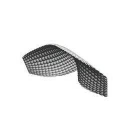
Concrete design offers flexibility in form generation unlike those of other construction techniques. Due to the process of concrete construction, an almost limitless variation of geometries can be achieved, where issues pertaining to common industrial standards limit the size and shape of forms created with other building systems.

In addition, global resources for the ingredients of concrete are widely available, and it offers a relatively inexpensive material to utilize for the creation of architecture (Allen and Iano, 517). Considering the consumption of concrete is second only to that of water, research regarding the intelligent implementation of concrete is of great importance (Allen and Iano, 517). An interesting and principal facet of concrete forming is it’s reciprocal relationship with an often invisible facet of concrete constructions, the formwork. In order to create concrete forms, the design of the formwork is crucial. From global geometries to surface textures, the formwork transcribes its properties into the form of the concrete cast. This relationship will be examined in the development of a environmental phenomena.
Current practices in concrete construction can be generaland precast concrete (Stacey, 33). The in situ process in-
lie. With precast concrete, the concrete is cast off-site
drawbacks of the comparison between systems is that though pre-cast concrete panels have a high degree of geometric tolerance, the limitation of size due to transportation and the continuity of surface are apparent. There are
Through using modular and reusable formwork, systems such as gang-formed, jump-formed and a variety of different other hybrid systems keep control of tolerances through high precision formwork and rapid formwork assembly and disassembly.
The majority of these systems, though, have relatively rigid geometries, with little ability for casting geometric variations. Thus, with most systems, high repetition of modular sections must be negotiated with higher costs of creating variations within each formwork type.
Formwork

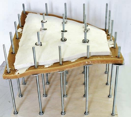
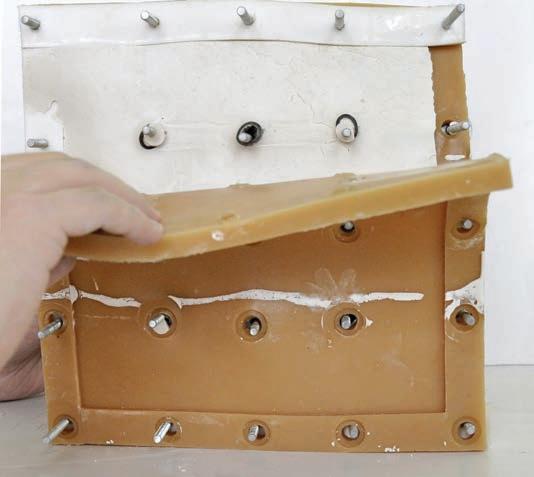
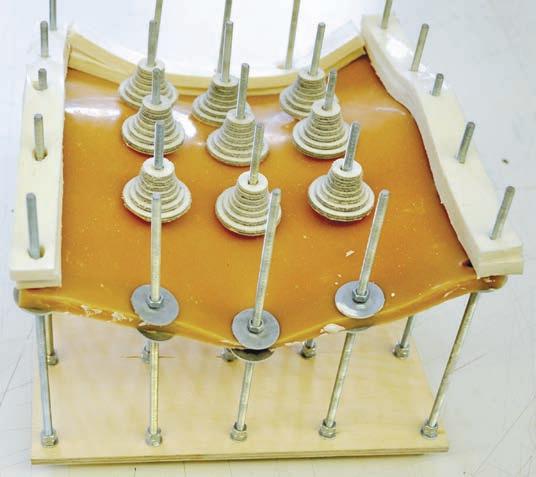
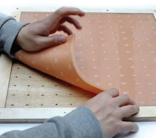
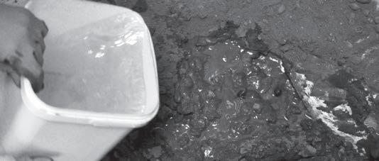
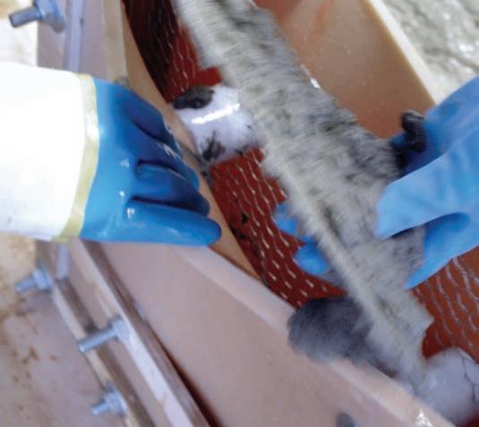
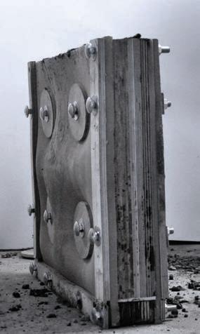
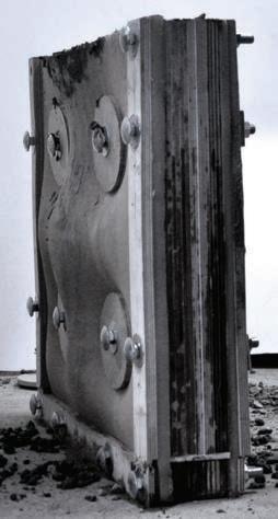
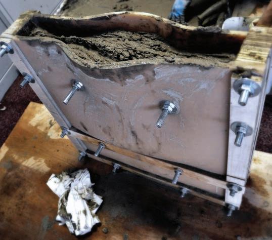
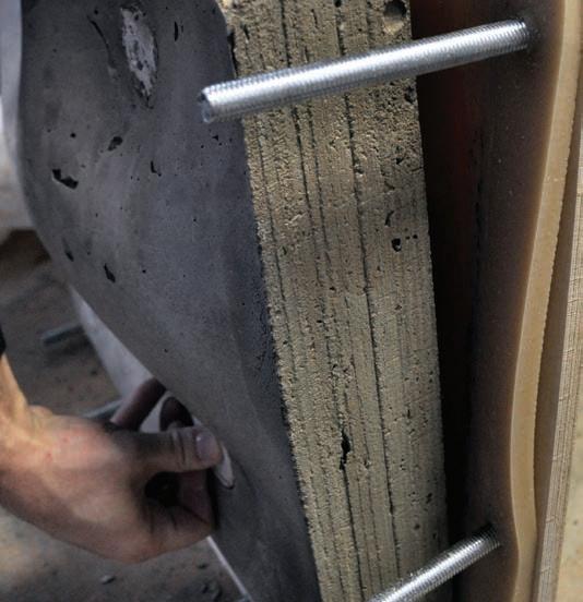
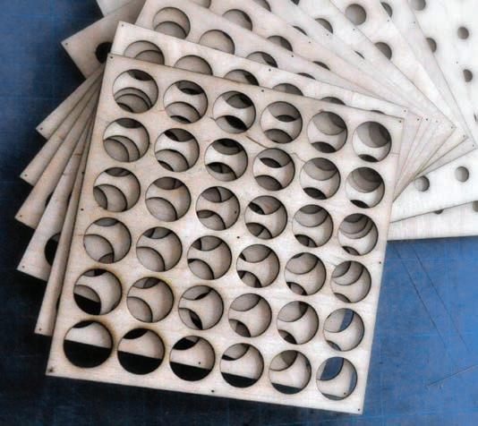
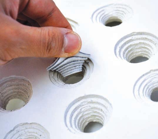
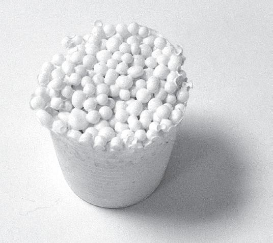
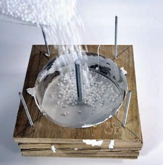
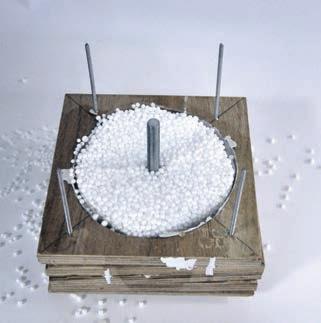
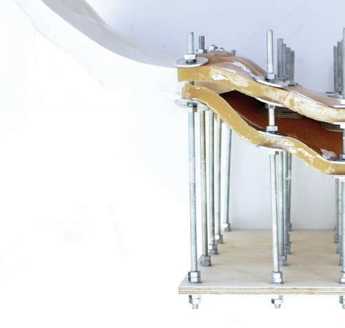
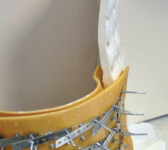
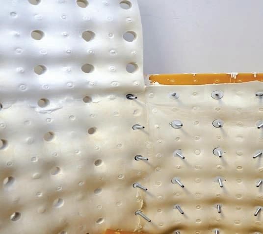
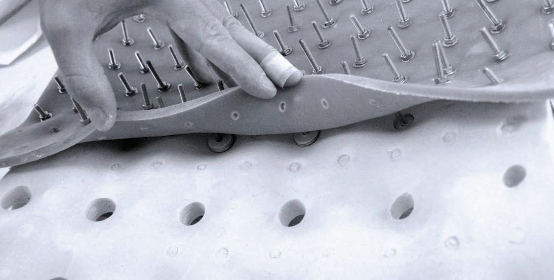
The research began with a series of physical experiments were undertaken in order to test differing casting methods and the properties of different formwork materials.
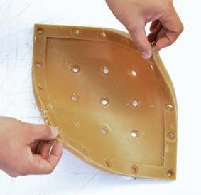
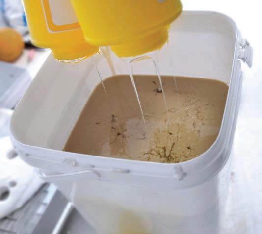
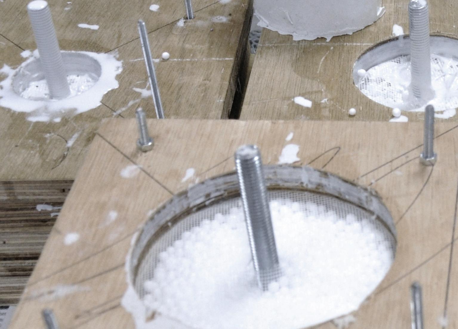
Three different polyurethane formwork sets were created to test specific criteria addressed in the research. The process of creating polyurethane rubber was explored.

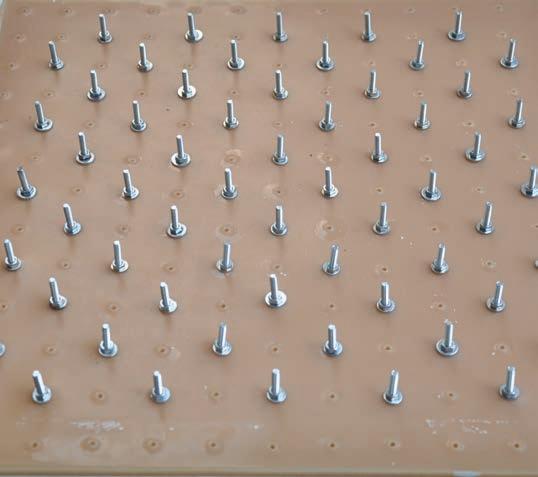
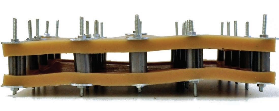
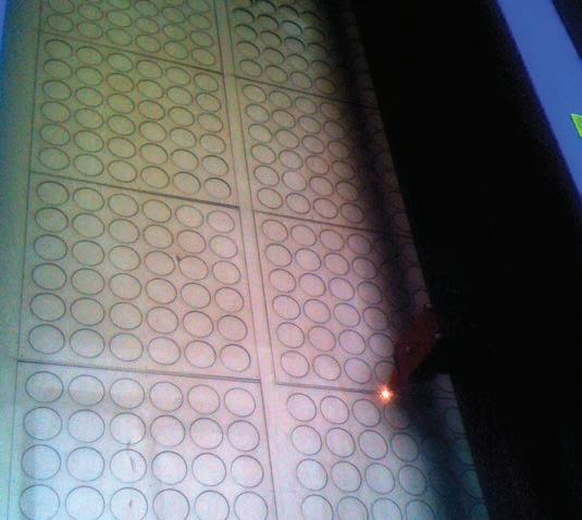
The research readapts a pre-existing and commonly used method of creating concrete surfaces. Most concrete formwork contain ties that travel through the concrete cast to tether two, usually treated plywood, together along with other exterior frames. This is why many exposed concrete are remnants of the formwork system.
What is essential when pouring concrete, is the ability to create a container for the liquid concrete as long as it takes to allow the concrete to cure into a rigid mass. In
load of the concrete is usually prevented. This results in highly robust and rigid systems that are engineered to resist the load of the concrete.
However, recent works with fabric formwork shows some
effects, such as variations in curvature and lighting qualities, were a natural consequence of the fabric form-
ate with the highly rigid systems.
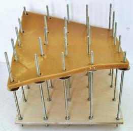
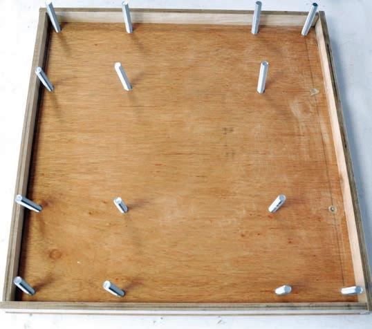
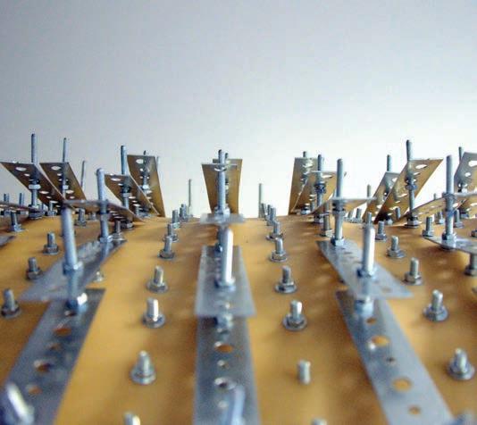
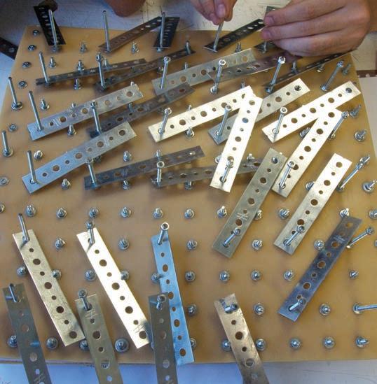
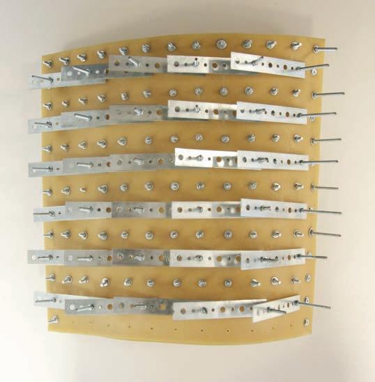
Considering, the research investigates primarily vertically oriented casting, watertightness and effects of hydrostatic pressure were of initial concern. Geometric adaptability with a single formwork was created through exterior control systems. Ease of fabrication and repetition of similar actions was considered in the assembly and disassembly sequences of the construction process.
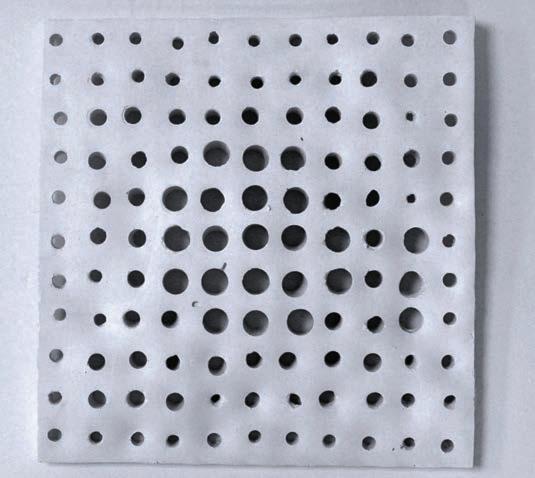
The acoustic effects of the research were tested within an isolated acoustic chamber, where each cast was tested with the same band of frequencies to observe the measurable differences between different concrete geometries.






















































 Bounding Box (reflected)


