25 minute read
M. Tocci, L. Montesano, A. Pola, S. Ferri.......................................................................................................... pag


Evaluation of fracture toughness in HPDC aluminium alloys to estimate crashworthiness in automotive parts
I. Tarhouni, D. Frómeta, A. Lara, S. Parareda, M. da Silva, D. Casellas, S. Wiesner
Aluminum high pressure die casting (HPDC) alloys are widely applied in the automotive sector. The constant needs for lightweight materials open a new opportunity for Al castings in structural applications in vehicles. New HPDC Al alloys with high ductility are available and are potential candidates for Body-in-White applications with crash requirements. Therefore, an assessment of the crashworthiness of these materials is required. In previous publications, the authors demonstrated that the fracture toughness, measured in the frame of fracture mechanics can be related to crash resistance in high strength steels and aluminum sheets. In this context, the characterization of the fracture toughness of two aluminum alloys with different ductility (AlMg4Fe2, AlMg4Fe2Zn3) was assessed following linear elastic fracture mechanics (LEFM), in terms of ������ and elastic-plastic fracture mechanics (EPFM), in terms of the essential work of fracture, �� ��. The results show that LEFM is not suitable to evaluate the fracture toughness of HPDC alloys with a significant amount of plasticity. On the other hand, it is showed that ���� describes the fracture toughness for high ductility alloys and it is here proposed as a material property to predict the crashworthiness of ductile HPDC alloys.
KEYWORDS: ALUMINUM, HIGH PRESSURE DIE CASTING, CRASHWORTHINESS, FRACTURE TOUGHNESS, EWF
INTRODUCTION The electrification of cars, and the control on the CO2 emission and fuel consumption are pushing automakers toward adopting lighter structures. New materials and forming processes have been developed in the last years to meet these demands, as advanced high strength steels (AHSS) and high strength aluminum alloys [1]. Aluminum high pressure die casting (HPDC) alloys are widely applied in the automotive sector. Their ability to create lightweight parts without sacrificing the strength, and their distinctive features such as corrosion resistance, excellent electrical conductivity and high stability for complex shapes make them good candidates for powertrain parts, bodyin white and chassis. Recent developments in HPDC have provided new opportunities for structural parts in electrical vehicles [2, 3, 4]. However, their efficient implementation depends on the ability of the car industry to optimize the fatigue and fracture performance.
Crashworthiness is one of the relevant material properties for lightweight construction of structural automotive parts. However, it is a complex property to measure. It Ilef Tarhouni, David Frómeta, Antoni Lara, Sergi Parareda, Manel da Silva
Eurecat, Centre Tecnològic de Catalunya, Unit of Metallic and Ceramic Materials, Spain
Daniel Casellas
Eurecat, Centre Tecnològic de Catalunya, Unit of Metallic and Ceramic Materials, Spain - Division of Solid Mechanics, Luleå University of Technology, Sweden
Stuart Wiesner
Rheinfelden alloys, Germany is usually measured with expensive and time-consuming tests, which often do not inform about the intrinsic material resistance to crash. Thus, Al manufacturers and carmakers are constantly looking for laboratory scale tests to characterize the crash behaviour and the fracture resistance. The work of Frómeta et al. showed that tensile properties such as the fracture elongation or the energy under load-displacement curve failed to provide a good characterization of the crashworthiness of AHSS [5]. Alternatively, some works in AHSS pointed that the fracture toughness, measured within the framework of fracture mechanics, is the relevant material property to describe the fracture resistance in crack related processes, like edge-cracking and crash tests [6,7]. More recently the work of Pujante et al. also showed that fracture toughness could be used to rank crashworthiness in high strength Al sheets [8]. Thus, fracture toughness emerges as a relevant material property to estimate crash resistance. The fracture toughness evaluation of thin parts, as thin sheets used in chassis and Body-in-White parts or thinwalled components obtained by HPDC, is experimentally challenging, because fracture toughness is thickness dependent. Specimen thickness defines if plain strain or plain stress fracture conditions prevail. Most of the standardized tests are defined for thick specimens, under plane strain condition. In addition, the lack of experimental standards to evaluate the fracture toughness when the thickness requirement is not fulfilled hinders the proper knowledge of their fracture resistance. In response to this need, the essential work of fracture approach was introduced in the frame of EPFM to determine the fracture toughness for ductile metal sheets under plane stress state [9,10].
This paper aims to assess the evaluation of fracture toughness of two HPDC aluminium alloys with different ductility range, with the objective to define the best approach to estimate crashworthiness at lab scale. Two fracture toughness approaches based on LEFM (�� ��) and EPFM (�� ��) were presented and discussed.
THEORETICAL PRINCIPALS LINEAR ELASTIC FRACTURE MECHANICS, ��
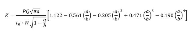
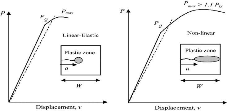
���� The plane strain fracture toughness, ������, is the crackextension resistance under mode I and linear-elastic conditions at the onset of 2% of the crack extension. The test procedures to measure it is defined in ASTM-E399 standard. The method involves testing fatigue precracked notched specimen. The most used specimens are C(T) and SE(B). The load-displacement curve is recorded during the test. ���� corresponds to 2% apparent increment of crack extension and established by a 0.95 deviation from the linear portion of the recorded curve as indicated in Fig.1. From the ���� value and the measured crack length for each test, the conditional fracture toughness ���� is calculated using the equation:
Eq (1)
where a is the crack length, t0 is the sheet thickness, W is the specimen width and b is the half of specimen width. Since ������ is thickness dependent i.e., toughness decreases with increasing the specimen size until reaching a plane strain mode, the following validity requirements are imposed to ensure that the measured ��
Eq (2)
where σ ys is the 0.2 % offset yield strength and Pmax is the maximum load recorded during the test. The second requirement, Eq (3) is to ensure that the non-linearity observed corresponds to the crack initiation and not to large plastic zone in the ligament [9].
ELASTIC-PLASTIC FRACTURE MECHANICS, ��
�� The essential work of fracture (EWF) concept proposes that the work performed at the crack region of a ductile material fractured under elastic-plastic condition and plane stress state (wf) is proportional to the ligament length (��0) and can be separated into two parts: (i) the essential work of fracture performed in the inner fracture process zone (�� ���� is thickness independent.
Eq (3)
��) and (ii) the non-essential work of fracture performed in the outer fracture process zone (w p) [6]. The total work of fracture (wf) can be written then as:
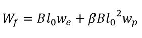
Eq (4)
where �� is a constant, which depends on the shape of the plastic region. Thus, by testing a series of geometrically similar specimens, the separation of the two energies is possible. Eq (4) is valid only if the ligament between the two notches is fully yielded prior to crack initiation and the plastic zone is uncontained within the ligament Fig.2. The test is usually performed on double edge notched (DENT) specimens.
Fig.2 - (a) DENT specimen ;(b) Linear relationship between total specific work and the ligament length and determination of ��
(a) (b)
�� at the y-axis intercept.
MATERIALS Two high performance HPDC Al alloys were used in this study: AlMg4Fe2 (Castaduct-42) and AlMg4Zn3Fe2 (Castaduct-18) alloys. The chemical composition and the tensile properties are listed in tables 1 and 2. METHODS DENT specimens of 120 x 60 x 3 mm (H x W x T) were used for the LEFM tests. The edge notches were machined by electrical discharge machining (EDM) then followed by a fatigue pre-crack of 1.5mm. The ligament length is about 14 mm (a/b=0.8) as indicated in Fig.3. The test was performed at a quasi-static strain rate of 1 mm/min with a gauge length of 25mm. The EWF experimental test was carried out on a batch of specimens with a ligament length varying between 6 and 14 mm, 2 samples were used for each ligament length. The test conditions, fatigue pre-crack and gauge length were the same as for LEFM tests. The values of wf were obtained by integrating the area under the load displacement curve and dividing by the cross-section area. ��
Tab.1 - Chemical composition (wt%) of Castaduct-42 and Castaduct-18. The balance in Al.
Alloy
Castaduct-42
Castaduct-18
Alloy
Castaduct-42
Castaduct-18 Si Fe Mg Cu Mn Zn Ti
Min. 1.5 4.1
Max. 0.2 1.7 4.5 0.2 0.15 0.3 0.2
Min. 1.5 4.1 3.3
Max. 0.2 1.7 4.5 0.2 0.15 3.6 0.2
Tab.2 - Tensile properties of Castaduct-42 and Castaduct-18.
Yield strength [MPa] Tensile strength [MPa] Total Elongation [%]
121
187 259
311 19.4
6.9
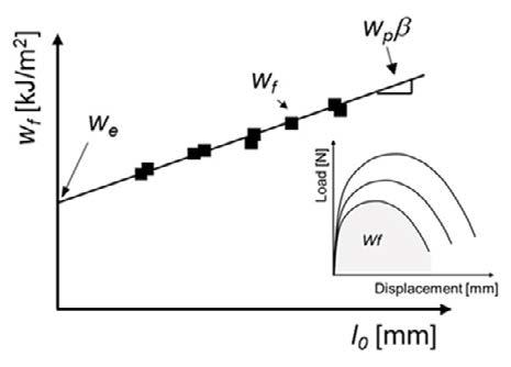
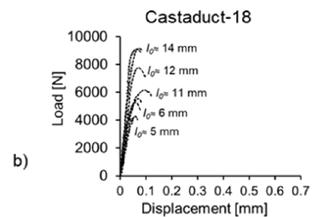
was determined from the extrapolation of wf vs l0 data to zero ligament length. Details about the experimental procedure are detailed in previous works [4,5,7]. The simulation of the experimental test has been made by finite element (FE) code” ABAQUS”. Due to the symmetry in the geometry and loading condition, only 1/8th of the geometry has been modeled. To reproduce the real behavior of the material, the true stress-strain curve obtained from a tensile test was introduced in the model. A 3D eight-nodes element was used for the FE calculation. For the crack tip, singular elements were used and a finer mesh to improve the accuracy. The analysis was performed in the elastic regime and several contours were employed around the crack tip to calculate the energy release rate. RESULTS AND DISCUSSION EXPERIMENTAL RESULTS Values of 13 MPam1/2 and 18 MPam1/2 were calculated for Castaduct-42 and Castaduct-18 respectively (Fig.3). The validity requirements were then checked for both alloys. The Castaduct-18 fulfilled the first requirement as (Pmax/PQ=1.1). On the other hand, the ratio exceeded 1.1 for the Castaduct-42 (Pmax/PQ=1.3). Consequently, ���� is meaningless and not giving a toughness value for the Castaduct-42. LEFM is then applicable only in the case of Castaduct-18. EPFM should be assumed in the more ductile alloy. To verify if ���� is equivalent to ������ in the case of Castaduct-18, the specimen size requirement must be met. A value of 25.8 mm of thickness should be satisfied for this alloy, much higher than the thickness of the specimens (3 mm). Therefore, ���� cannot be considered as ������ , then it is the fracture toughness for the tested thickness.
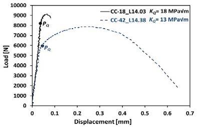
Fig.3 - ��
�� determination from load-displacement curves of Castaduct-18 and Castaduct-42.
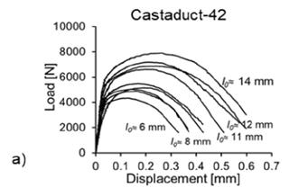
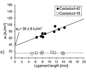
Typical load-displacement curves of the DENT specimens obtained from the EWF experiments are shown in Fig.4. It can be observed that the curves are self-similar for both alloys. The Castaduct-42 showed a larger area under the load displacement curve compared to Castaduct-18, which is consistent with their higher ductility. On the other hand, the Castaduct-18 reached higher maximum load. The sharp drop after the maximum load indicates a more brittle fracture behaviour, which is also consistent with their low ductility. Fig.4 shows the evolution of ���� vs ��0 for both alloys. It is observed that ���� linearly scales with ��0 in the case of Castaduct-42, which indicates that the premises of
energy separation given by the EWF protocol are valid. The measured toughness in terms of ��
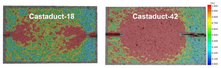
��,is 36 kJ/m2 . However, ���� does not change for different specimens in Castaduct-18, which means that the EWF approach is not valid for the case of Castaduct-18 alloy. Digital Image Correlation (DIC) technique was used to examine the evolution of the plastic zone in the ligament zone during the fracture process. DIC results confirmed that the complete yielding condition, necessary for the validity of the EWF method, was extensive and proceeded the crack initiation in the case of Castaduct-42 but fails for Castaduct-18. Thus, EPFM does not describe the behaviour of low ductility alloys. Fig.4 - Load-displacement curves and EWF for Castaduct-18 and Castaduct-42. Fig.5 - DIC measurements of the plastic zone ahead of the crack tip for the two studied alloys.
NUMERICAL RESULTS
Since the conditional toughness ���� is meaningless for Castaduct-42 alloy, only Castaduct-18 is modelled. The Von Mises stress distribution is shown in Fig.6. The low degree of plasticity in the ligament zone can be seeing.
Several contours were used for the calculation of KI. It can be seen from table.3 that the last several contours give independent results. The KI extracted from the FE model agrees well with the value obtained in experimental LEFM tests (table 4). Fig.6 - Von Mises stress distribution at the crack tip.

Tab.3 - Stress intensity factor in mode I (KI) extracted form FE modelling at different contours.
KI [MPa.mm 1/2] Castaduct-18
Position contour 1 contour 2 contour 3 contour 4 contour 5 contour 6
Middle of the crack font 606.7 629.8 632.4 633.1 633.3 632.7
Tab.4 - Comparison between experimental and FE modelling results.
SUMMARY AND CONCLUSIONS • The development of a significant amount of plasticity at the crack tip in the case of the ductile HPDC alloy (Castaduct-42) restrained the use of LEFM. Thus, EPFM method should be used for high ductility alloys. • LEFM can be applied to low ductility HPDC alloy (Castaduct-18). • The characterization of fracture resistance of the HPDC
Al alloys developed for crash applications must be done in the frame of EPFM. In this sense, the Essential
Work of Fracture methodology gives reliable values of fracture toughness. It is proposed as a testing method to estimate crashworthiness for HPDC alloys with high ductility. • The numerical verification of the path independence exhibits results that confirm the robustness of the implementation of LEFM toughness.
ACKNOWLEDGEMENTS This work was financially supported by the Catalan Government through the funding grant ACCIÓ-Eurecat (Project Optilightmat-2020).
Castaduct-18 Experimental (MPa.m1/2) Numerical (MPa.m1/2)
18 20
[1] Miller, W. S., et al. Recent development in aluminum alloys for the automotive industry. Materials Science and Engineering: A 280.1. 2000; 37-49. [2] Zhou, J., et al. Advanced aluminium products and manufacturing technologies applied on vehicles presented at the EuroCarBody conference. Materials Today: Proceedings. 2015; 2 (10), 5015-5022. [3] Kuziak, R. et al., Advanced high strength steels for automotive industry. Archives of civil and mechanical engineering. 2008; 8(2), 103117. [4] VISNIC, B., (2020, June 02). Tesla casts a new strategy for lightweight structures. In automotive engineering. https://www.sae.org/ news/2020/06/tesla-model-y-big-castings. [5] Frómeta, D. et al. On the correlation between fracture toughness and crash resistance of advanced high strength steels. Eng. Frac. Mech. 205. 2019; 319-332. [6] Casellas, D., et al. Fracture toughness to understand stretch-flangeability and edge cracking resistance in AHSS. Metallurgical and Materials Transactions A, 48(1). 2017; 86-94. [7] Pujante, J., Frómeta, D., Garcia-Llamas, E., Giménez, M., Casellas, D. Hot stamped aluminium for crash-resistant automobile safety cage applications, Materials Science Forum. 2021, 1016 MSF, pp. 445–452 [8] Cotterell, B., Reddel, J. K. The essential work of plane stress ductile fracture. International journal of fracture.1977; 13(3), 267-277 [9] Frómeta, D., Parareda, S., Lara, A., Molas, S., Casellas, D., Jonsén, P., Calvo, J. Identification of fracture toughness parameters to understand the fracture resistance of advanced high strength sheet steels. Engineering Fracture Mechanics. 2020; 229, 106949. [10] Zhu, X. K., Joyce, J. A. Review of fracture toughness (G, K, J, CTOD, CTOA) testing and standardization. Engineering Fracture Mechanics. 2012; 85, 1-46.
Temperature and microstructural condition dependence for thermal diffusivity and thermal condutivity of a casting Al-Si-Cu-Mg alloy
E. Gariboldi, C. Confalonieri, R. Wang, M.C. Poletti, B. Stauder, R. Fernández Gutiérrez
Thermal and electrical properties as well as mechanical properties of age-hardenable Al alloys are affected, both at room and at high temperature, by their microstructural condition. This behaviour has to be considered not only for wrought but also for casting alloys, such as for the Al-7Si-0.5Cu-0.4Mg, characterized by multiple precipitation sequences investigated in the paper. In these conditions the temperature dependence of thermophysical properties, generally obtained performing tests during isochronal heating, is not only related to the initial microstructural condition, but also to heating rate, a test parameter whose range is often limited by testing methodologies and equipments. These effects have to be taken into account in cases where a multipurpose material characterization or a comparative analysis of result is intended to interpret microstructural changes. Ex-situ tests can help the separation of microstructural changes effect from temperature-related ones. Examples of the combined techniques and analyses are illustrated.
KEYWORDS:Al-7Si-0.5Cu-0.4Mg, TEMPERATURE-DEPENDENCE, THERMAL DIFFUSIVITY, ELECTRICAL CONDUCTIVITY, DILATOMETRY
INTRODUCTION Among the widely applied Al-Si-Mg alloys, the simple addition of Cu demonstrated to beneficially improve the high temperature performance [1, 2], so that temperature and stress/strain cycles can be withstood by complex-geometry components without the addition of exotic elements. When these alloys, with excess Si and Cu-containing, are solution treated and artificially aged, secondary Si intragranular particles adds up to the metastable phases of β-Mg2Si precipitation sequence [3] and to phases of the quaternary Q-phase one [4]. The relatively high dissolution temperatures and slow coarsening kinetics of these phases lead to increase both temperature and time at which particle strengthening occurs with respect to Al-Si-Mg alloys. As for other age-hardening alloys intended to be artificially aged (AA) or serviced at relatively high temperature, the following points should be considered: i) local cooling rate following a solution heat treatment (SHT) affect precipitate evolution during aging/service, both in terms of precipitate, volume fraction, nucleation sites and kinetics; ii) secondary phases affect not only strength, but also on the change of volume of the alloy, iii) secondary phase-related effects E. Gariboldi, C. Confalonieri
Politecnico di Milano, Dipartimento di Meccanica (Italy)
R. Wang, M.C. Poletti
TU Graz, Christian Doppler Lab. for Design of high-performance alloys by thermomechanical processing, TU Graz (Austria)
B. Stauder, R. Fernández Gutiérrez
Nemak Linz GmbH, Linz (Austria)
can be observed also for thermal or electrical properties. In parts of complex geometry and service conditions, the interaction between all these features is not easy to foreseen and good understanding of separate effects should be considered. Focusing on point (i), the effect of SHT and of its final cooling on further precipitation during aging treatments at 180-230°C of Al-7Si-0.5Cu-0.4Mg alloy with homogeneous solidification structures was shown to be negligible for SHT cooling rates exceeding 10-20 K/s by Ram et al [6] and will be not investigated in the present paper. Concerning points (ii) and (iii), the temperature-dependence of age-hardening alloys can significantly differ from that of commercially pure Al, with thermophysical properties both to initial microstructure and heating rate in the widely adopted isochronal-type tests, where adopted heating rates are related to test methodology and equipment used to obtain specific properties. Multiple characterization techniques and heating rates can be successfully used to improve the interpretation of microstructural changes, well exemplified in [7]. Whenever the multipurpose material characterization could include only a limited set of tests, or lab equipment has different operating ranges, the set-up of experiments should be taken into account. The possibility to split microstructural condition from test temperature effects, and of excluding this latter could also be helpful for these analyses. A comparative analysis of characterization methods is here proposed for Al-7Si-0.5Cu-0.4Mg where multiple precipitation sequences of low amount of secondary phases occur. This paper shows the effects induced by initial temper and testing conditions on in-situ dimensional stability and thermal diffusivity, and ex-situ electrical conductivity.
MATERIALS AND EXPERIMENTALS
Tab.1 - Chemical composition of the investigated alloy (mass %).
The investigated material was an Al-7Si-Mg-Cu alloy (actual chemical composition given in Table 1). Cylinder heads parts were cast by the Rotacast®-method, where the crucible and attached mould slowly rotate around a defined horizontal axis, allowing the liquid metal to progressive and regularly fill the mould. 15X15 mm2 section bars were machined from as cast parts in regions where SDAS was close to 32 m [6]. Cylindric samples for dilatometric tests (5 mm diameter, 20 mm length) and discoidal samples (12.7 mm, 2 mm thickness) for thermal diffusivity and eddy current tests were machined from these bars. In order to test the alloy in different temper conditions, in addition to the samples in the as-cast (AC) condition (tested some months after casting), other sets of samples were solution heat treated (SHT) at 530°C for 4.5 h and quenched in water at about 15°C/s. Some specimens were tested immediately after SHT or stored at -18°C before testing. (SHT+AA4h) condition was obtained after SHT followed by, artificial aging at 230°C for 4h to obtain an overaged [6], but rather microstructurally, mechanically and dimensionally stable condition. Ex-situ indirect electrical conductivity measurements at 20°C were performed by eddy current with frequency 60 kHz with an 8 mm diameter probe. Sets of 5 measurements were performed on water cooled samples extracted from a ventilated oven following set thermal cycles. Specifically, these ex-situ tests were performed at different times during the heat treatment of SHT+AA4h sample to check the sensitivity of the method to microstructural changes. Later, the tests were performed on AC, SHT, SHT+AA4h samples, during isochronally furnace heating from 20 to 530°C at 1°C/ min and 10°C/min rates, corresponding to those adopted in thermal diffusivity and dilatometric tests. Thermal diffusivity of samples in the three alloy conditions were performed by means of Laser Flash Analyzer during heat cycles 20-530-20°C in vacuum with an average heating rate of 1°C/min (0.6-2°C/min actual range). Dilatometric tests on different initial conditions have been performed on a vertical dilatometer equipped with quartz rod, with 20-530-20°C heating/cooling cycles at 10 and 1°C/ min. RESULTS AND DISCUSSION Electrical conductivity The room temperature electrical conductivity of a single specimen at different times of the heat treatment cycle is correlated to the microstructural condition, as shown in Figure 1-left, where the temperature profile of the heat treatment is plotted in blue color. Figure 1 presents the average of the 5 measurements; standard deviation data are not shown, and they range between 0.01 and 0.025 MS/m depending on the material condition. During the first isothermal treatment, the initial high electrical conductivity of the AC sample decreased within the first few minutes spent at 530°C to an almost constant value. The following isothermal aging treatment at 230°C brought a progressive increase of the electrical conductivity that is still increasing after 4h holding. This behaviour can be correlated to the amount of elements remaining in solid solution in the α -phase at different time. This simplified explanation further neglects the effects different solute elements and of the presence of secondary phases. At the high SHT temperature, elements rapidly diffuse and with high solubility, such as Mg and Si, rapidly enter in solid solution causing a rapid decrease of electrical conductivity. During the artificial aging stage, the formation of second phases progressively depletes the matrix of solute elements, thus increasing its electrical conductivity. It can be worth mentioning that at this aging temperature the alloy reaches peak hardness in about 1 hour [2], after which electrical conductivity still increases. The results of isochronal ex-situ electrical conductivity tests on AC, SHT, and SHT+4hAA samples are shown in Figure 1-rigth. The general trend can still be explained in terms of solid solution content (mainly of Mg and Si). First, above 200°C precipitates form in SHT sample, while they increase in AC sample and, in a less extent, in overaged sample. Then, the conductivity starts to decrease due to solid solution above about 350°C, converging to the same value for all the samples, since the final microstructural condition is the same. The increase of electrical conductivity occurs more rapidly and at lower temperatures for low temperature rates. Only above about 450°C, the differences between different heating rates and initial material conditions reduce. In the SHT sample, the increment of the conductivity is higher than in AC and SHT conditions due to the highest change in element solubility.
Fig.1 - Results of ex-situ electrical conductivity tests performed at room temperature during two-step isothermal heat cycle on AC sample simulating SHT and artificial aging (left) and isochronal heating tests at 1 and 10°C/min performed on specimens in different initial conditions (right).
THERMAL DIFFUSIVITY The results of temperature-dependent thermal diffusivity for the investigated alloy in three different initial conditions are shown in Figure 2. The thermal diffusivity (D) is directly correlated to the thermal conductivity (λ), and inversely to the density ρ and the specific heat cp: (D = λ/(ρ*c p)). The diffusivity in the alloy have roughly the same temperature trend as the thermal conductivity, at least in conditions where and both density and cp have smooth and minor changes (for example related to secondary phases).
Si Cu Mg Fe Mn Ti Al
6.83 0.531 0.379 0.107 0.073 0.12 Bal.
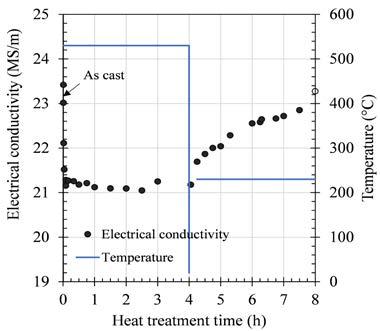
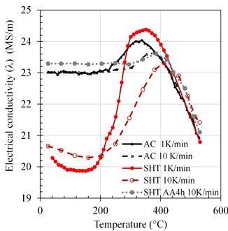
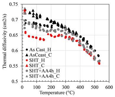
Fig.2 -Temperature-dependency of thermal diffusivity (D) for the investigated alloy in three different initial conditions. For each experimental condition, data taken during the heating and cooling parts of the cycle are plotted with different symbols (H and C, respectively) to highlight their differences.
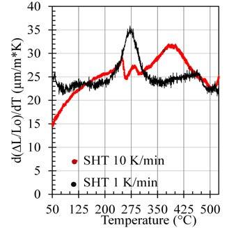
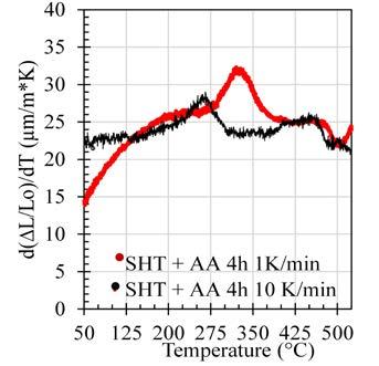
Experimental data taken during the slow isochronous heating and cooling are plotted with different symbols to highlight the correlation of thermal diffusivity to the actual microstructural composition at the moment at which the measurement was taken. During heating up to about 350400°C, the three curves became closer. The trend of the curve is also the same during the slow cooling from 530°C. The complete separation of temperature-only effects from those related to microstructural changes is not possible in these in-situ tests. Nevertheless, the abovementioned correlation of diffusivity to thermal conductivity and the Wiedemann–Franz law, correlating which states that the ratio between thermal conductivity and electrical conductivity increases with temperature [9], allow a simplified approach for thermal diffusivity evolution. This can be considered as the overlapping of the decreasing trend for pure aluminium overlapped to changes related to alloying atoms in solid solution, as discussed for electrical conductivity. The approach allows comparison between these later trends and those for ex-situ electrical conductivity. In SHT condition, their solute atoms decrease more significantly with respect to initial content, provoking a large drop in the diffusivity values. Above 150-200°C, the data for initial conditions converge, with an increased effect of solute atoms that reduces diffusivity more rapidly than for pure aluminium [8]. originated by a unit change in temperature (coefficient of thermal expansion) is not constant, but it shows peak/valleys (Figures 3a and 3b) whose position depends on the initial microstructural condition and heating rate. These changes can be correlated to the formation/dissolution of different phases, whose specific volume differs from that of the matrix. Thus, the amount of the phases present at each temperature change the actual specimen length with respect to the general trend of a constant coefficient of thermal expansion. Specifically, in the case of casting Al-Si-Mg [9] and wrought Al-Mg-Si alloys [10], where the amount of Si exceeds that for the only formation of precipitates of the β-Mg2Si sequence, the precipitation of secondary silicon particles with diamond structure causes an increase of specimen length [9], while the formation of precipitates of β-Mg2Si and their dissolution in Al-Mg- Si alloys do not correspond to any peak/valley in dilatometric curves [9]. Fig.3 - Results of dilatometric tests performed at 1 and 10 °C/min heating rate on samples of the Al- Al7Si-0.5Cu-0,4Mg after Solution Heat Treatment (left) and after further aging at 230°C for 4 h (rigth).
The identification of peaks on the basis of dilatometric tests only is not straightforward, as in DSC analyses. The peak of elongation corresponding to Si formation can help the identification of peaks in materials characterizations involving both techniques. In the present cases, DSC tests and TEM analyses show that the nucleation of secondary Si starts in a temperature range between 230°C and 280°C, and concurrently β” Mg5Si6 transforms into β’-Mg1.8Si [10]. This is compatible with the upward peak obtained in the present work on the SHT sample at 10°C/min and also to the absence of the same peak in the specimen artificially aged for 4 hours tested at the same heating rates. . The kinetics for the formation and dissolution of secondary Si and their related phases is a function of the heating rate: the higher the heating rate, the higher temperature needed for precipitation of secondary Si.
CONCLUSIONS AND FINAL REMARKS The simple testing program carried out on the Al-7Si-MgCu alloy demonstrate that thermo-physical properties of age-hardenable alloys are both temperature- and microstructure- dependent, with this latter effect being more significant for the metastable SHT condition. The temperature dependence of thermal diffusivity of the three samples gives an example of this. From the point of view of material characterization in view of making data available for the design of high-temperature, long-term service components, the more stable aged/serviced material could be more suitable than initial unstable material. Alternatively, the progressive change of properties during aging/service should be taken into account, adding complexity to the modelling of thermal diffusivity. Similar consideration could be done for dilatometric tests and for temperature-dependent electrical conductivity tests (not considered here). Under less unstable conditions the material properties are also less affected by the heat cycle selected to investigate the temperature-dependence of properties (heating/cooling rates in isochronal tests). In age hardening alloys isochronal tests for one or a set of thermophysical properties could be also used as a tool to investigate by relatively simple tests, the microstructural changes taking place within the material,aiming for example at modelling their kinetics. The heating rates available for different property and equipment are often not overlapping. Considering the thermal diffusivity, dilatometry and calorimetric tests here mentioned, the latter are more often performed at low heating rates (0.2-6°C/min are for example reported in [7]), while the set heating rate can increase up to 40°C/min in several DSc equipment, with the smallest sample and furnace sizes. Without mentioning the advantages/disadvantages of adopting high or low heating rate for different techniques, the adoption of a wider range for them and the possibility of clear identification of microstructural changes can help to study complex kinetics of phase transformations. Lastly, The possibility to carry out ex-situ tests (in this case electrical conductivity) on a quenched microstructure was observed to eliminate the temperature effect from that of the microstructural changes induced by isothermal or isochronous. This tool, allowing to operate with different heating rates, represents an additional tool for the identification of thermal events-microstructural change
DILATOMETRIC TESTS The results of dilatometric tests show that the thermal strain