27 minute read
E.W. Jarfors, C.K. Jammula, R. Ghasemi ............................................................................................ pag


[8] Mørtsell, A.E., Marioara, C.D., Andersen, S.J., Ringdalen, I.G., Friis, J., Wenner, S., Røyset, J.; Reiso, O., Holmestad, R.: “The effects and behaviour of Li and Cu alloying agents in lean Al-Mg-Si alloys” (pp.235-242) Journal of Alloys and Compunds. 23 December 2016. DOI: 10.1016/j.jallcom.2016.12.273 [9] Koshino, Y., Kozuka, M., Hirosawa, S., Aruga, Y.: “Comparative and complementary characterization of precipitate microstructures in Al–Mg–Si(–Li) alloys by transmission electron microscopy, energy dispersive X-ray spectroscopy and atom probe tomography” (pp.765-770) Journal of Alloys and Compunds. 7 November 2014. DOI: 10.1016/j.jallcom.2014.10.199 [10] Ozaydin, O., Armakan, E., Kaya, A. Dokumacı, E., (2019) The Effects of Artificial Ageing Conditions on A356 Aluminum Cast Alloys. ECHT 2019 European Conference on Heat Treatment, Bardolino / Italy. [11] Nikolay A. Belov Dmitry G. Eskin Andrey A. Aksenov. (2005) Multicomponent Phase Diagrams: Applications for Commercial Aluminum Alloys (pp.257-286) Elsevier Science eBook ISBN: 9780080456966 DOI:10.1016/B978-0-08-044537-3.X5000-8 [12] Xiaokun Yang, Baiqing Xiong, Xiwu Li, Lizhen Yan, Zhihui Li, YongAn Zhang, Hongwei Liu, Hongwei Yan and Kai Wen (2019) Mater. Res. Express 6 IOP Publishing Ltd https://doi.org/10.1088/2053-1591/ab4f06
Numerical simulation of the effects of a Phase Change Material (PCM) on solidification path of gravity sand cast Al-Cu alloy
Z. Noohi, B. Niroumand, G. Timelli
Solidification structure has a significant effect on mechanical and physical properties of metallic materials and its control is a main direction in the research for the improvement of materials performance. Various methods, such as control of cooling rate, inoculation, imposing vibration and pressure, are traditionally used to control the solidification structure during casting and solidification processes. In this paper, the preliminary results of a new method for controlling the solidification structure during casting using Phase Change Materials (PCMs) are presented. The evolution of the solidification structure of a directionally chilled Al-Cu alloy poured in a silica sand mould with and without the use of pure zinc as a PCM was examined using experimental and simulation methods. It was shown that the PCM temperature could reach about 510 °C during the solidification of the aluminium alloy, therefore, absorbing its melting latent heat from the solidifying aluminium alloy melt which affects its local solidification cooling rate. Therefore, the solidification structure of the sample cast in the PCM fitted mould differed from that of the sample without PCM. While macrostructures of both samples showed the transition from columnar to equiaxed grains, the columnar zone in the PCM sample was larger than in the sample without PCM. In other words, columnar to equiaxed transition (CET) for the sample without PCM occurred sooner than that for the sample with PCM. In addition, the average size of the equiaxed grains at the Chill sample is smaller than the PCM sample.
KEYWORDS:MACROSTRUCTURE CONTROL, GRAVITY SAND CASTING, PHASE CHANGE MATERIALS (PCMS), COLUMNAR TO EQUIAXED TRANSITION (CET)
INTRODUCTION Aluminium casting alloys have huge applications in automotive, sport, and aerospace industries because of such special properties as excellent thermal and electrical conductivity, appropriate castability, reasonable weldability, lightweight and good corrosion resistance [1, 2]. It has been established that different processing parameters including cooling rate [3], application of electric and magnetic fields [4] and directional solidification [5] can affect the casting macro and microstructure as well as the solidification path. Using metal or graphite chillers is another way to control the final casting structure as well as to produce castings with minimum shrinkage defects. Different types of chiller materials such as copper, iron, or aluminium based alloys as well as graphite can be used according to their heat capacities and diffusivities. It is obvious that each of these materials can absorb and transfer a specific amount of heat before saturation by heat. Therefore, both type and dimenZohrehsadat Noohi
Department of Materials Engineering, Isfahan University of Technology, 84156-83111, Isfahan, Iran
Behzad Niroumand
Department of Materials Engineering, Isfahan University of Technology, 84156-83111, Isfahan, Iran
Giulio Timelli
Department of Management and Engineering, University of Padova, 36100, Vicenza, Italy
sions of chillers have an important role on heat transfer, cooling rate, and solidification microstructure of the castings [6]. Obviously, larger chillers are required for higher heat absorption, and the areas closer to the chill experience higher cooling rates resulting in the formation of fine columnar microstructures [7]. In this paper, a new way to control the solidification macrostructure of metallic alloys by using Phase Change Materials (PCMs) is proposed. PCMs are materials that can absorb or release their latent heat at a relatively constant temperature (their melting temperature) during the solid-liquid transition [8]. PCMs are mainly used in such applications as buildings [9] and solar systems [10] to save heating energy. In this study, a PCM has been incorporated into a metal chiller and its effect on the cooling and solidification macrostructure of a directionally solidified Al-Cu alloy is investigated using experimental and simulation methods.
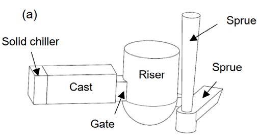
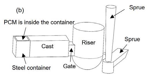
EXPERIMENTAL PROCEDURE ALLOY AND CASTING METHOD Al-4.5wt.%Cu-0.2wt.%Fe alloy, low carbon steel and commercially pure zinc were considered as the poured metal, chiller and PCM, respectively. Schematics of the casting moulds are illustrated in Fig. 1. The moulds were made of sodium silicate bonded silica sand. The casting dimensions were 30×30×70 mm3. In order to provide enough time for melting of the PCM (pure Zn) during solidification of the AlCu alloy and to further encourage directional solidification of the castings, alumina insulation (not shown in the figure) was used around the casting cavity. The Al-Cu alloy was melted and superheated to 750 °C in a graphite crucible using a resistance furnace and cast in two moulds fitted either with a chill (Chill sample) or with PCM (PCM sample), as shown in Fig. 1. In the Chill sample, a solid chiller with 30×30×13 mm3 dimensions was placed at the end of the casting. In the PCM sample, a steel container with 30×30×25 mm3 dimensions and wall thickness of 2 mm filled with pure zinc was used. In order to evaluate the effects of the latent heat absorption of the PCM on the cooling rate and solidification structure of the Al-Cu alloy, dimensions of the PCM and the encasing box were selected in a way that they had the same cooling power as that of the solid chiller up until the melting of the PCM. For recording the temperature during the pouring and solidification of the alloy, three K-type thermocouples were located in the castings at 10, 35 and 60 mm from the chill surface. One thermocouple in the chiller (in the Chill sample) and two thermocouples in the PCM (in the PCM sample) were also employed (Fig. 2). The temperature data was collected using a data acquisition system with a sampling rate of 1 s-1, analog-to-digital converter accuracy of 0.1°C, which was linked to a personal computer.
Fig.1 - Schematics of the casting moulds: (a) Chill sample and (b) PCM sample.
MACROSTRUCTURE INVESTIGATION In order to study the macrostructure of the castings, longitudinal sections of the cast samples were ground by silicon carbide (SiC) papers to 600 grit and etched with Keller etchant (1.5 ml HCl, 2.5 ml HNO3, 1 ml HF and 95 ml distilled water). CASTING SIMULATION Before casting, the optimum mould designs were obtained based on numerical simulation with ProCast 2018 software. Tetrahedral mesh number was chosen 209517 for the casting, 17078 for the chiller, 43510 for the steel container, 71214 for the PCM, 124499 for the runner system, 285639 for the insulator and 431920 for the mould. The heat transfer coefficients were selected according to Tab. 1. The mass flow was selected at 200 g/s.
Tab.1 - Heat transfer coefficients (HTC) between different interfaces of the moulds.
Cast-Chill Cast-Insulator Cast&Runner- Mould PCM-Chill InsulatorMould Chill-Mould
Chill sample 4500-5500 200 PCM sample 8000-10000 200 900 --- 50
1000 9000-15000 50
RESULTS AND DISCUSSION EXPERIMENTAL RESULTS Fig. 2 demonstrates the collected experimental temperature-time (T-t) curves of both Chill and PCM samples at different positions. According to Fig. 2, for the Chill sample, all the thermocouples in the casting rapidly reached 750 °C and then were cooled gradually. The chiller temperature also reached 600 °C. On the other hand, for the PCM sample, the temperature reaches about 600 °C at 10 and 35 mm from the chill surface before dropping down suddenly and rising again to 600 °C in less than 100 s. Then they continue a gradual cooling process. At 60 mm from the chill surface, the temperature reaches 750 °C, then cools down to about 650 °C where it remains almost constant for about 150 s and then starts to decrease. The differences among the curves at the early stages of the casting are thought to be related to the turbulence of the melt during metal pouring when the molten metal may touch the thermocouples temporarily. Furthermore, the T-t curves of two positions inside the PCM is shown in Fig. 2. It shows that the PCM temperature at position Zn1 reaches the melting point of the pure zinc, i.e. 419.5 °C, after 11 s and finally reaches about 510 °C after 40 s. The PCM temperature at position Zn2 reaches its melting point after 30 s and finally increases to about 500 °C after 120 s. The latent heat absorption effect of the PCM is evident in the curve corresponding to Zn2. According to Fig. 2, at the early stages, the PCM sample has cooled faster than the Chill sample because of the effect of PCM melting. The thermophysical properties of zinc are different from steel. The specific heat coefficient of pure zinc, at both solid and liquid phases, is less and its heat conductivity is more than steel [11, 12]. Therefore, the heat transfer in the PCM sample would be more than that in the Chill sample, resulting in a faster temperature drop in the PCM sample. Moreover, when the pure zinc starts to melt at the early stages, it absorbs its latent heat from the Al alloy. This extra heat absorption is believed to affect the cooling rate and, consequently, the macrostructure of the aluminium alloy casting.
(a) (b)
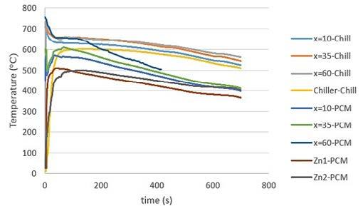
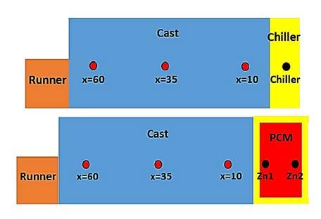
Fig.2 - (a) Experimental T-t curves for both PCM and Chill samples and (b) Location of three thermocouples at 10, 35, and 60 mm from the chiller surface in both PCM and Chill samples, one thermocouple in the chiller (Chill sample) and two thermocouples, i.e. Zn1 and Zn2, in the PCM (PCM sample).
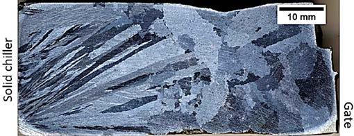
Fig. 3 illustrates the macrostructures of both samples. Each macrostructure consists of a columnar structure grown on the chill surface followed by an equiaxed grain structure towards the ingate of the casting. A clear CET (Columnar-Equiaxed Transition) is observed in both castings. Length of columnar regions, measured using ImageJ analysis software, is equal to about 38 and 41 mm for Chill and PCM samples, respectively. According to Fig. 3(a), a distinct difference between the two macrostructures is that solidification in the chill sample appears to has started from the lower corner of the steel chill and the columnar grains have grown towards the upper surface of the Chill sample. On the other hand, all the columnar grains grew uniformly perpendicular to the chill surface in the PCM sample with a direction opposite to that of the heat transfer. The difference is believed to be related to the air gap between the PCM and the steel container. In the Chill sample, when the molten metal first touches the lower part of the solid steel chiller during pouring, an intense heat transfer sets in, resulting in rapid nucleation and growth of grains from the contact area. The total chilling capacity of the solid chiller is concentrated on this small contact area. Due to the large volume of the chiller, it is not easily saturated by the transferred heat. As a result, the grains grow in the opposite direction to the heat transfer. Therefore, these localized nucleation and heat transfer phenomena at the lowest corner of the chiller have determined the grain orientation of this sample. In the PCM sample, however, the PCM is encapsulated in a 2 mm thick steel container. When the molten metal comes in contact with the steel chiller, the PCM cannot effectively participate in the heat transfer at the beginning due to the presence of an air gap between the PCM (pure Zn) and the steel chiller. Therefore, the steel container wall heats up quickly avoiding a localized heat transfer from the first con-
(a) tact points. The air gap is practically removed when the encapsulated PCM melts. Melting of the PCM, on the one hand, increases the heat transfer between the casting and the chiller/PCM assembly and, on the other hand, absorbs its latent heat from the casting. As a result, the cooling rate of the PCM sample increases and its solidification time decreases resulting in a larger columnar zone compared to those of the Chill sample, as shown in Fig. 4. The average size of the equiaxed grains was calculated by the lognormal distribution method [13]. According to related equations, the average grain sizes are 1.8 ± 1.3 mm and 2.2 ± 1.8mm for the Chill and PCM samples, respectively. Previous researches have shown that by determining the thermal gradient (G) at the solid-liquid interface and the solid-liquid interface velocity (R), it is possible to predict the CET formation [14-16]. It has been shown that CET will occur when the G/R ratio decreases and reaches below a critical value. Upon decreasing the thermal gradient in front of the solid-liquid interface, the constitutional undercooling in front of the solidification front increases and equiaxed grains can grow in an unconstrained manner [15]. In this work, the measured amount of G/R (according to the simulated T-t curves) at the time of CET formation was about 14.9 and 0.05 °C·s/cm2 for the Chill and the PCM samples, respectively. Higher G/R value in the Chill sample means that CET took place at a higher thermal gradient and/or smaller solidification growth. In other words, the formation of CET at the Chill sample is easier than that in the PCM sample. Therefore, in the Chill sample, the equiaxed zone has occurred at a closer distance to the chiller surface, and as a result, has a finer macrostructure.
(b)
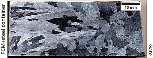
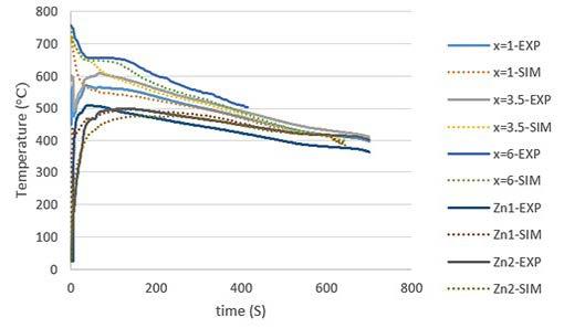
Fig.3 - Macrostructure of (a) Chill and (b) PCM samples. SIMULATION RESULTS Figs. 4(a) and 4(b) show the experimental and simulation T-t diagrams of the Chill and PCM samples, respectively. As it is observed, there is a good agreement between the simulation and the experimental data. The cooling rate near the liquidus temperature was measured at different points according to the simulation diagrams in the temperature range of 644-634 °C. The cooling rate at the chiller/casting interface (x=0 mm) for both samples is about 28.6 °C/s suggesting how the dimensions of the chiller and PCM were correctly designed, i.e. they provide a similar chilling effect at the beginning. At a distance of 10 mm from the chiller, the cooling rate at the mushy zone near the solidus temperature is about 4.6 and 7.7 °C/s for the Chill and the PCM specimens, respectively. At greater distances (x=35 and x=60 mm), the cooling rates in the PCM sample are even larger than those in the Chill sample. These differences are thought to be due to the presence of the PCM (pure zinc), i.e. because of different physical properties in comparison to solid steel chiller and its melting at the early stages of casting solidification. As a result, the chilling powers in both samples were similar before melting the PCM, but the cooling rate and solidification conditions changed after melting the PCM.
(a) (b)
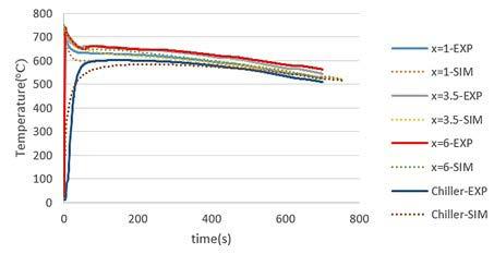
Fig.4 - Experimental and numerical cooling curves for (a) Chill and (b) PCM samples.
CONCLUSION In this paper, a novel method to control the solidification macrostructure of an Al-Cu alloy using Phase Change Materials (PCMs) was studied using experimental and simulation approaches. The results showed that the incorporation of a zinc PCM into a metal chiller affected the cooling and solidification conditions of a directionally solidified Al-Cu alloy. Columnar to Equiaxed Transition (CET) was observed in both samples. However, it occurred later for the sample fitted with the zinc PCM. The effects are believed to be due to absorption of the latent heat of melting of the PCM during the early stages of solidification of the casting as well as the different thermophysical properties of the PCM and chill materials. Based on the results, the proposed method can be used as an innovative cooling system to control the solidification macrostructure of the castings.
ACKNOWLEDGMENTS ZN would like to thank Isfahan University of Technology (IUT), Iran, and the Ministry of Science, Research and Technology of Iran for the financial supports, and the University of Padova (Italy) for providing some of the required pieces of equipment.
REFERENCES
[1] Qi M, Li J, Kang Y. Correlation between segregation behavior and wall thickness in a rheological high pressure die-casting AC46000 aluminum alloy. J. Mater. Res. Technol. 2019; 8: 3565-3579. [2] Babaee M.H, Niroumand B, Maleki A, Lashani Zand M. Simulation and experimental verification of interfacial interactions in compound squeeze cast Al/Al–Cu macro composite bimetal. T NONFERR METAL SOC. 2019; 29: 950-963. [3] Agrahari S, Panda I, Patel F. M, Gupta M, P. Mohanty C. Effect of cooling rate on microstructures and mechanical property of Al 1230 alloy in a sand casting process. Mater. Today: Proc. 2020; 26:1771-1775. [4] He C, Li Y, Li J, Xu G, Wang Z, Wu D. Effect of electromagnetic fields on microstructure and mechanical properties of sub-rapid solidification-processed Al–Mg–Si alloy during twin-roll casting. Mater. Sci. Eng. A. 2019; 766. [5] de Souza Baptista L.A., Paradela K. G, Ferreira I. L, Garcia A, Ferreira A. F. Experimental study of the evolution of tertiary dendritic arms and microsegregation in directionally solidified Al–Si–Cu alloys castings. J. Mater. Res. Technol. 2019; 8: 1515-1521. [6] Campbell J. United Kingdom: Butterworth-Heinemann; 2015. 204-207 p. [7] Campbell F.C. United States of America: ASM International; 2012. 433-436 p. [8] Lazzarin, R.M, Mancin S, Noro M, Righetti G. Hybrid PCM—aluminium foams’ thermal storages: an experimental study. Int. J. LowCarbon Technol. 2018; 13: 286-291. [9] Sun D, Wang L. Research on heat transfer performance of passive solar collector-storage wall system with phase change materials. Energy build. 2016; 119: 183-188. [10] Mousa H, Gujarathi A.M. Modeling and analysis the productivity of solar desalination units with phase change materials. Renew. Energy. 2016; 95: 225-232. [11] Smithells C.J. London and United States of America: Elsevier; 2013. 941-943 p. [12] MatWeb. Overview of materials for Low Carbon Steel (Last visted on 20/8/2021) [13] Crow E. L, Shimizu K. Lognormal distribution. United States of America: 1998. [14] Dong H. B, Lee P. D. Simulation of the columnar-to-equiaxed transition in directionally solidified Al–Cu alloys. Acta Mater. 2005; 53: 659-668. [15] Hadadzadeh A, Shalchi Amirkhiz B, Li J, Mohammadi M. Columnar to equiaxed transition during direct metal laser sintering of AlSi10Mg alloy: effect of building direction. Addit Manuf. 2018; 23: 121-131. [16] Mahapatra R.B, Weinberg F. The columnar to equiaxed transition in tin-lead alloys. METALL MATER TRANS B. 1987.
Characterization of microstructural and mechanical properties of high-pressure die-cast en ac 46000 alloy
M. Tocci, S. Ferri, L. Montesano, A. Pola
The present research focuses on the characterization of microstructural and mechanical properties of real castings produced by HPDC using EN AC 46000 alloy. The Cu content of the alloy was varied inside the limits prescribed by the standard for EN AC 46000 alloy to investigate the influence of Cu on the material performance and to provide results useful for industrial applications. Castings with Cu content of 2 wt.% and 4 wt.% were industrially produced using a 2500-ton HPDC machine. Two areas of the casting with different cooling rates were selected to obtain samples for microstructural and mechanical characterization. In particular, area fraction, number density and equivalent diameter of intermetallic compounds were investigated, and the size distribution of these particles were statistically evaluated. Finally, hardness measurements and tensile tests were performed and the results were correlated to microstructural features and solidification conditions to deeply understand the alloy behavior.
KEYWORDS:HIGH PRESSURE DIE CASTING, MICROSTRUCTURE, INTERMETALLICS, TENSILE PROPERTIES
INTRODUCTION Al-Si-Cu alloys are widely used for high-pressure die-casting (HPDC) processes. In particular, AlSi9Cu3 alloy (EN AC 46000) is frequently applied for the production of various components by HPDC, especially for the automotive industry. In fact, nowadays it offers many advantages, such as high productivity rate, low cost, possibility to obtain castings with complex shapes, thin walls and smooth surfaces, while the fast solidification ensures good microstructural properties. Nevertheless, the formation of porosities is a typical problem, which is emphasized in HPDC by the rapid filling able to create turbulences in the liquid metal flow. Another critical aspect from the microstructural point of view is the presence of high amounts of intermetallic particles containing Fe [1]. On the other hand, Fe has also beneficial effects in die-casting since it plays the important role of reducing the phenomenon of die soldering of the casting [2]. Several researchers deeply investigated the effect of Fe, Mn and Cr on intermetallics morphology and formation [3], while few studies examined the effect of Cu on the properties of a die-casting alloy [4,5]. In fact, the effect of Cu addition to casting alloys has mainly been studied for primary Al alloys with low Fe content [6,7] where Cu is adMarialaura Tocci
Department of Mechanical and Industrial Engineering, University of Brescia, via Branze 38, 25123, Brescia
Sara Ferri
Ghial Spa, Via Giuseppe Angelo Ghidoni, 4, 25045 Castegnato BS
Lorenzo Montesano
Department of Mechanical and Industrial Engineering, University of Brescia, via Branze 38, 25123, Brescia
Annalisa Pola
Department of Mechanical and Industrial Engineering, University of Brescia, via Branze 38, 25123, Brescia
ded to improve mechanical properties (especially for high temperature applications [8]),applied in other processes, as such as gravity or low pressure die casting. Regarding the effect of Cu to a secondary AlSi9Cu3 die casting alloy, Fabrizi et al. [4] observed a high porosity level for the alloy with the highest Cu content, which is expected to be detrimental for material performance, as discussed also by other researchers [9]. Instead, Outmani at el. [5] found that, despite the high porosity, the alloy with the highest Cu content (approximately 3 wt.%) showed enhanced tensile strength. Similar effect of Cu was documented also by Lumley et al. [10]. It has to be mentioned that in these studies several parameters were changed, as the content of other alloying elements, injection temperature and pressure [5,10] and therefore it is difficult to clearly identify the role of Cu. For these reasons, it is believed that further studies on this topic are necessary to exploit the alloy performance from both a scientific and industrial point of view. Therefore, the present research focuses on the commercial alloy EN AC 46000, whose Cu content was modified inside the range prescribed by the alloy standard (i.e. from 2 up to 4 wt.%). Furthermore, samples were taken from an actual casting of significant size and not from castings obtained at laboratory scale, as usually described in scientific literature [4,9,11] to make this study as close as possible to the industrial field. The aim is to quantify the influence of Cu content on microstructural features (especially intermetallic phases and porosity level) and mechanical properties.
EXPERIMENTAL PROCEDURE The present study was carried out on castings obtained by HPDC process with EN AC 46000 alloy (often indicated as AlSi9CuFe alloy). Five castings with the minimum (i.e. approximately 2 wt. %) and maximum Cu content (i.e. approximately 4 wt. %) allowed for EN AC 46000 alloy were produced. The chemical composition of the final castings is shown in Table 1, as obtained from measurements by optical emission spectrometer.
Tab.1 - Mean chemical composition of the final castings.
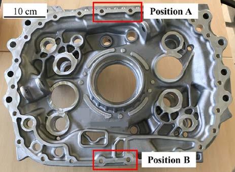
Fig.1 - Picture of the casting used for the present study with indication of the analyzed areas. The microstructure of samples was observed by means of an optical microscope Leica DMI 5000 M, equipped with LAS image analyzer, on mirror polished samples. Average secondary dendrite arm spacing (SDAS) was calculated for each sample, according to the linear intercept method. Furthermore, porosity level was calculated by digital image analysis on a total area of 15 mm2 for each sample. The main phases and intermetallic compounds present in the samples were characterized by means of a scanning electron microscope (SEM), LEO EVO 40 equipped with an Energy Dispersive Spectroscopy (EDS) probe for elemental analysis. Digital image analysis was carried out on twenty SEM images (backscattering mode) for each alloy for both the positions considered in order to evaluate the area fraction, equivalent diameter, and number density (number of particles per unit of area) of intermetallic particles. Results in terms of equivalent diameter of these particles were further statistically evaluated by means of JMP® software. Finally, tensile specimens were machined to final shape according to UNI EN ISO 6892-1 standard (sample diameter of 4 mm and gauge length of 20 mm). Tensile tests were carried out with a Galdabini Quasar testing machine at room temperature. The elongation was measured using a knife-edge extensometer fixed to the gauge length of the specimens. The crosshead speed was set at 3 mm/min in the elastic field and at 9 mm/min in the plastic one. Three samples were tested for each condition and average and standard deviation were calculated for ultimate tensile strength (UTS), yield strength (YS) and elongation (El. %) values extrapolated from strainstress curves. Based on tensile tests results, the Quality Index, frequently used in foundry, was calculated as indicated by Drouzy et al. [14].
RESULTS First, the sludge factor was calculated for both the alloys and values in the range 1.8-2 were found. In addition, the temperature of the holding furnace (675 °C) was slightly below the critical temperature for sludge formation (687 °C for Cu2 alloy, 682 °C for Cu4 alloy), suggesting the likely formation of primary intermetallic particles in the furnace. This is consistent with the calculation of sludge area fraction in the casting, which is estimated to be approximately 1%. This represents a limited area fraction of primary intermetallic particles, which nevertheless has to be considered to thoroughly understand material performance. Finally, according to the charts reported by various authors [12,15], no sedimentation of sludge in holding furnace is expected. Regarding microstructural properties, the SDAS values in position A are slightly higher than in position B for both the alloy compositions (Table 2). It follows that in the former case the solidification rate is lower than in the latter and, easily leading to different mechanical properties. In addition, in Table 2, porosity level is indicated as measured from digital image analysis. Interestingly, it was found that the average porosity of sample Cu4-A is only slightly higher than Cu2-A, despite the higher Cu content. On the other hand, Cu4-B samples is characterized by the highest porosity level (above 1 %), suggesting that in this case the formation of eutectic intermetallic phases due actually hindered liquid feeding leading to significant microporosity formation. The faster solidification, due to the colder zone, combined with the higher distance from the gate, hindered the effect of pressure in compensating shrinkage and filling the interdendritic regions, giving rise to high porosity.
Alloy Si Cu Fe Mn Mg Cr Ni Zn Pb Al
Cu2 8.025 2.097 1.097 0.296 0.125 0.094 0.095 0.918 0.058 Bal.
Cu4 8.298 4.104 1.033 0.231 0.149 0.095 0.111 1.031 0.089 Bal.
The sludge factor was calculated for both the alloys [12], as well as the critical temperature for sludge formation [12]. In addition, the area fraction of sludge that can form in the holding furnace was evaluated [13]. Samples for microstructural and mechanical characterization were taken from two different positions in the casting (indicated in Fig. 1) in order to evaluate different cooling conditions for each alloy. In particular, the position A is located near the gate and corresponds to the warmer zone (i.e. which solidifies more slowly), while the position B is located opposite to the gate and corresponds to the coldest zone (i.e. which solidifies faster).
Tab.2 - Average values of SDAS and porosity for the studied samples.
Sample Cu2-A Cu2-B Cu4-A Cu4-B
SDAS (μm) 19 ± 2 13 ± 3 20 ± 1 16 ± 1
Porosity (%) 0.55 ± 0.10 0.20 ± 0.05 0.65 ± 0.20 1.25 ± 0.30
For each sample, various intermetallic particles were also identified and analyzed using SEM-EDS (Fig. 2).
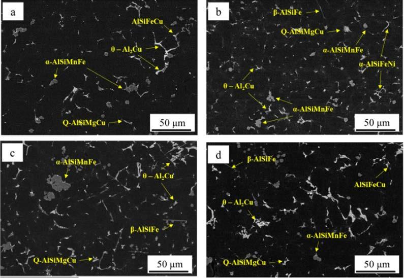
Fig.2 -SEM images and intermetallics identification for a) Cu2-A, b) Cu2-B, c) Cu4-A and d) Cu4-B samples.
Results from digital image analysis shown in Table 3, in terms of area fraction and number density of intermetallic particles, supported the evaluation of the presence of intermetallic particles.
Tab.3 - Analysis of intermetallic particles in the studied samples.
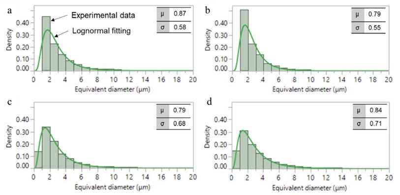
For Cu2 alloy, the different cooling conditions between position A and B do not significantly affect the total amount of intermetallic particles since area fraction and particles density are comparable. On the other hand, the increase in Cu content leads to a higher area fraction of intermetallics than for alloy Cu2, especially in position A where the area fraction is the double in comparison with samples Cu2-A. Interestingly, for sample Cu4-B the area fraction of intermetallic particle is reduced. This can be ascribed to the different cooling conditions of the analyzed samples. In position A, based on SDAS measurements, it is expected to have a lower solidification rate, and this allows intermetallic particles to grow, resulting in the observed high area fraction. Further evaluation of the size of intermetallic particles was carried out in terms of equivalent diameter of the particles. In this regard, it is reported that that the size of intermetallic particles follows a two-parameters lognormal distribution [16]. This was verified also in the present study, as shown in Fig. 3, where the lognormal probability density function was used to fit experimental data of equivalent diameter obtained by digital image analysis. The shape parameter μ and the scale parameter σ, estimated from lognormal distribution are also indicated. Fig.3 - Experimental data and relative lognormal fitting for intermetallic particles in the studied samples as a function of equivalent diameter: a) Cu2-A, b) Cu2-B, c) Cu4-A and d) Cu4-B samples.
It can be observed that particles size distribution is quite similar for all the investigated conditions and that most particles have an equivalent diameter below 6 μm. According to [17], these can correspond to proeutectic intermetallic particles, as opposed to primary sludge particles, which are characterized by bigger size. This is not surprising since the studied alloys are characterized by a limited sludge factor (SF = 1.8-2). This is also consistent with the limited expected sludge area fraction (approximately 1 %, as above-mentioned), while the total area fraction of intermetallic particles ranges from 4 to 8% in the investigated samples (Tab. 3). Tensile properties of the studied alloy are shown in Fig. 4.
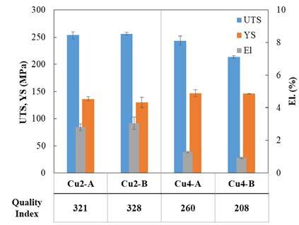
Fig.4 - Tensile properties of studied samples.
Samples with low Cu content exhibit quite similar values of tensile strength. This is consistent with the similar content of intermetallic particles, while the minimum amount of porosity for sample Cu2-B may be responsible for its slightly higher elongation. When Cu4 alloy is considered, it appears that ductility is significantly reduced and that also UTS is decreased, even if not so strongly. On the other hand, an increase in YS can be appreciated. The loss in UTS and elongation for Cu4-A sample can be explained considering that this sample is characterized by the highest area fraction of intermetallic particles, which have a brittle behavior and easily detach from the Al matrix during tensile testing. The poor performance of Cu4-B samples, despite the lower number of intermetallic particles, is instead related to the high porosity level, which diminishes the load bearing area of the samples,
Area fraction (%) Particles density (particles/mm²) Cu2-A Cu2-B Cu4-A Cu4-B
4.1
2.8 ·103 4.6
2.9 ·103 8.2
4.9 ·103 6.0
3.5 ·103