26 minute read
Z. Noohi, B. Niroumand, G. Timelli................................................................................................... pag


higher high-temperature strength and thus greater resistance to thermal shock cracking. The special transformation behaviour of CS1 enables martensitic transformation with great certainty when hardening large dies. Practical tests carried out by our customers show that dies made of CS1, thanks to its significantly higher hardness, show a noticeable improvement in performance, especially for castings with the highest surface requirements.
[1] Spotlightmetal [Internet]. Technologies: Robert Knorre; 2019. Automotive Structural Parts made in HPDC; 2019 Dec 12 [cited 2021 Jan 29]; [1 page]. Availabe from: https://www.spotlightmetal.com/automotive-structural-parts-made-in-hpdc-a-888708/ [2] Information/Age [Internet]. Data&Insight: Aaron Hurst; 2020. Global 5G connections to reach 3.6 billion in 2025 — CCS Insight: 2020 Oct 13 [cites 2021 Feb 08]; [1page]. Available from: https://www.information-age.com/global-5g-connections-reach-3-6-billion2025-ccs-insight-123492091/ [3] Haberling E., Schüler P. Zusammenhang zwischen Vergütungsfestigkeit und Temperaturwechselrissbildung von Warmarbeitsstählen. Thyssen Edelst. Techn. Ber. 1985 Sep; 11(2):158-161
AM Process Simulation to Optimise Diecasting Tooling
N. Gramegna, D. Boscolo, G. Scarpa, Nardo and F. Bonollo
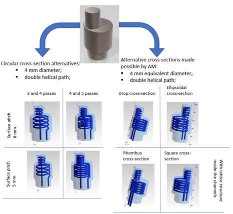
The innovation of design for diecasting tooling is significantly affected by Additive Manufacturing (AM) technology evolution as well as by the increasing reliability of AM process simulation [3]. The casting process simulation is a well-known standard design procedure to optimize the thermal steady state of each part of the steel die taking into account the limitation of traditional machining process to produce the insert with proper cooling channels [1,2]. The advent of Selective Laser Melting (SLM) or Electron Beam melting (EBM) is opening to free form of cooling channels to control the thermo mechanical behaviour of the steel tooling improving the die life and reducing the risk of local defect in the casting. Further possible development is the application of DED to reparation of the High pressure die casting (HPDC) tooling. The AM simulation tools can simulate different additive processes and various virtual scenarios can be evaluated. The Optimization of diecasting tooling is entering a new era thanks to material, technologies and virtual simulation tool of AM processes. The study described in this paper is a reference application of HPDC and AM simulation coupling the benefits of the two manufacturing processes. The thermo-mechanical performance of traditional diecasting insert is improved by conformal cooling channels and the cycle time is typically minimized. The SLM simulation validates the 3D printing of steel material taking into account the geometry compensation, the support optimization and the quality of printed part to be treated and machined. The cost- benefits analysis supports the decision in the design phase validating the optimal geometries for the production of the components, verifying the efficiency of the cooling channels designed to support the quality of the component and the dies life, maximizing the benefits and reducing costs [4].
KEYWORDS:PROCESS SIMULATION, ADDITIVE MANUFACTURING, STEEL INSERT, CONFORMAL COOLING, HIGH PRESSURE DIE CASTING, PROCESS OPTIMIZATION
INTRODUCTION High-pressure die casting process (HPDC) is one of the most exploited casting processes. Nowadays the process is used more and more to cast multitude of different sizes and far more complex castings. The principle of the HPDC process is that molten metal (mostly aluminum or zinc) is pressed into the cavity under high pressure. The cavity is filled in a few hundredths of a second. After the melt has solidified, the casting is removed from the open die and afterward the cavity surface is sprayed with a die lubricant water based and blown with air to avoid water stagnation. The die is then closed and ready to receive a new portion of molten metal. The permanent die undergoes severe thermal cycles, since the range of temperatures involved and the little cycle time. Thermoregulation during the heat removal is crucial not only to obtain a good quality part, but it also affects the die life and the production time cycle, cost-effectiveness of N. Gramegna, D. Boscolo, G. Scarpa
Enginsoft Spa, Italy
N. Nardo and F. Bonollo
University of Padova, Italy
the process results strongly dependent onto these factors. HPDC dies are made of hot working steel, such as H11 and H13. The complex cavity shape is conventionally obtained with machining processes (CNC, drilling, …), thermoregulation circuits are so restricted to straight line shapes. Thus, meaning that conventional thermoregulation circuits don’t impart optimal thermal (and thermomechanical) behavior, especially in case of great complexity of the cavity (such as curved-in shapes, thin thickness inserts, …). The advent of Additive Manufacturing (AM) for metals, and its consolidation declined in the Powder Bed (and Direct) methods, has paved the way for an innovative way of tooling, opening many possibilities on different levels. The design is freed from conventional tooling (machining) constraints, the material usage is lowered abandoning the subtractive conventional processes, design and different processes and scenarios can be easily evaluated through increasingly reliable simulation means. Conformal Cooling technique takes advantage of AM characteristics listed above, die inserts can so be equipped with free form and small diameter (down to 1.5 mm) cooling channels, enabling the redesign of the conventional die inserts, making feasible a much finer control of the thermomechanical behavior of the die. While the literature already explored and proved the value of applications of AM tooling for injection molding, it appears to be still pretty unexplored for HPDC. The aims of this paper are to: - build a DOE Analysis of conformal cooling application to an HPDC die insert to figure out the best alternative among the proposed layouts; - Assess techno-economical costs and benefits of a conformally cooled insert in comparison to a conventional insert;
The expected benefits introducing 3D printed inserts in the traditional HPDC tooling are the reduced cycle time (less solidification time), best casting quality (less defects) and prolongation of die life (less stressed tooling). To carry out this analysis in this paper simulation tools will be deployed. In particular thermal behavior of the insert and part quality will be evaluated through the utilization of MAGMASOFT®, while AM feasibility will be assessed through the Ansys® Print suit.
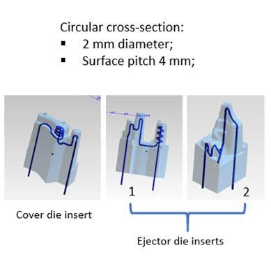
CONFORMAL COOLING DESIGN After the analysis of the conventional design it appeared that the main issue of the HPDC castings was to be found in localized porosity. To solve this issue four inserts where selected to be candidates, on their own or in different combinations, for conformal cooling circuits. The first of this insert is an actual separated insert already existing on the slider, the other three inserts where derived respectively one from the fixed and two form the ejector die. Due to the narrow dimensions of the spires of the three inserts on ejector and fixed die only one conformal cooling was designed for each, while with a bigger available volume eight alternatives have been designed for the side core insert. THERMAL ANALYSIS To evaluate the best alternatives a full factorial DOE was set up based on the created designs. Four factors were defined, three factors were set as the three circuits designed for ejector and cover die were set to be either active or not, the fourth factor took into account the side core insert, in its eight circuit designs plus the possibility of absence of any cooling circuit there. Four objectives have been set to minimize: porosity, porosity on an evaluation area, FS time and the sum of the active circuits. This generated 81 alternative designs, in table 1 the improvements of the DOE winning design in comparison to the conventional one; the winning design is characterized by 2 conformal cooling circuits: rotating ellipsoidal circuit for the side core die and the circuit of the ejector die insert 2;
Tab.1 - Achievements of conformal cooling in comparison to the conventional design.
Δ% porosity Δ% Temperature Δ% cycle time Δ% productivity
Conformal Cooling Design -95% -77.84% -16.47% +19.72%

Fig.2 - Critical porosities reduced using conformal cooling.
In addition to these results the die life of the side core insert was evaluated, showing impressive improvement too;
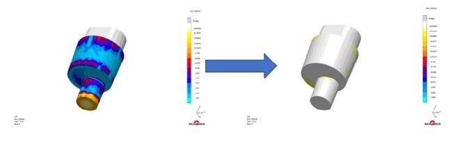
Fig.3 - Die life results improvement: on the left conventional design on the right conformal cooling design, showing a much longer die life duration through the colors on the top of the scale representing the number of cycles.
CFD ANALYSIS The production process analysis took into account also the fluid dynamics of the circuits (cfd analysis). Thanks to the definition of the medium, the medium temperature and the flow rate, it is possible to evaluate the efficiency of the circuits and possible leaks. In this specific case, water at 20 ° c with a flow rate of 20 l / min was the considered medium. The results show in particular that the thermal delta between input and output does not exceed 5 ° c, indicating a high efficiency of both circuits.
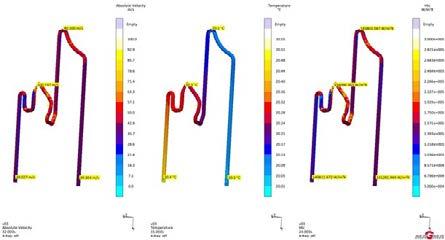
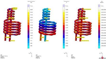
Fig.4 - Conformal cooling cfd analysis: velocity, temperature and HTC results.
AM FEASIBILITY For evaluation of manufacturability through L-PBF process of the inserts designed one relevant alternative was selected to be simulated, the side core insert equipped with the rotating ellipsoidal circuit. As already mentioned, the simulation of AM process will remain on a macroscopic scale. Exploiting Inherent Strain method, which is based on the strains evaluation. Lack of resources lead to impossibility to calibrate the material and strain scaling factors, therefore the results of this analysis give a qualitative idea of the most critical areas for deformation and stress, more than accurate magnitudes of these. The simulation enabled though, the construction of a compensated geometry and assessed the feasibility of the channels showing acceptable values of stress and deformation along the conformal channels.
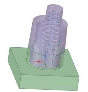
Fig.5 - Conformal cooling cfd analysis: velocity, temperature and HTC results.
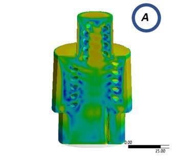
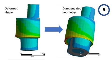
Fig.6 - Conformal cooling cfd analysis: velocity, temperature and HTC results. COST/IMPACT ANALYSIS The cost of a L-PBF produced insert is almost 10 times the cost of the same insert produced through conventional tooling due to: - Numerical evaluation Production cost 1.6 times higher - Energy consumption 1.8 times higher - Powder alloy costs 10 times higher than the same solid material But the higher production cost is justified by the following improvements assessed through simulation: - the waste castings rate is expected to decrease from a 50% to a 10%; - the down time for insert substitution considering a production of 1000000 of castings is lessened of the 100%; - the reduction of the solidification time and therefore cycle time reduction enables a rise of 19% of the production rate;
2. AM manufacturability of HPDC die inserts The first point may be considered achieved thanks to two aligned results. Firstly, the higher effectiveness of the HPDC manufacturing process is to be found in the improvement of the part quality, assessed by the reduction of the values of porosity, hot spot and die soldering effects. Secondly cost reduction of the process is to be found in the cycle time reduction, enabling a higher productivity and in the elongation of the die inserts through smaller thermal cycles, lessening hence the down time for insert substitution. The second point more specifically deals with the L-PBF manufacturability, which has been tested in terms of part deformation and residual stress and strains. The results of the set of AM simulations gave the basis to part compensations in order to obtain a printed part respecting the demanded specifications.
CONCLUSIONS AND FUTURE PERSPECTIVES Numerical evaluation of conformal cooling solutions for HPDC die inserts and L-PBF manufacturability of the have drawn an interesting scenario for the future application of these techniques and process in the industry. The most relevant achievements can be divided in two main categories: 1. HPDC process improved cost-effectiveness
REFERENCES
[1] J. Meckley and R. Edwards, “A Study on the Design and Effectiveness of Conformal Cooling Channels in Rapid Tooling Inserts,” Technol. Interface J., vol. 10, no. 1, pp. 1523–9926, 2009. [2] H. S. Park and N. H. Pham, “DESIGN OF CONFORMAL COOLING CHANNELS FOR AN AUTOMOTIVE PART,” Int. J. Automot. Technol., vol. 10, no. 1, pp. 87–93, 2009. [3] Y. Wang, K. M. Yu, C. C. L. Wang, and Y. Zhang, “Automatic design of conformal cooling circuits for rapid tooling,” CAD Comput. Aided Des., vol. 43, no. 8, pp. 1001–1010, 2011. [4] K. M. Au, K. M. Yu, and W. K. Chiu, “Visibility-based conformal cooling channel generation for rapid tooling,” CAD Comput. Aided Des., vol. 43, no. 4, pp. 356–373, 2011. [5] S. A. Jahan, T. Wu, Y. Zhang, J. Zhang, A. Tovar, and H. Elmounayri, “Thermo-mechanical Design Optimization of Conformal Cooling Channels using Design of Experiments Approach,” Procedia Manuf., vol. 10, 2017. [6] S. Jahan and H. El-Mounayri, “A Thermomechanical Analysis of Conformal Cooling Channels in 3D Printed Plastic Injection Molds,” Appl. Sci., vol. 8, no. 12, p. 2567, 2018. [7] A. Agazzi, V. Sobotka, R. Legoff, and Y. Jarny, “Optimal cooling design in injection moulding process-A new approach based on morphological surfaces,” Appl. Therm. Eng., vol. 52, no. 1, pp. 170–178, 2013. [8] Maciej Mazur Martin Leary Matthew McMillan Joe Elambasseril Milan Brandt, “SLM Additive Manufacture of H13 Steel with Conformal Cooling and Lattice structures Nomenclature,” Rapid Prototyp. J., vol. 22, no. 3, 2016. [9] M. Mazur, P. Brincat, M. Leary, and M. Brandt, “Numerical and experimental evaluation of a conformally cooled H13 steel injection mould manufactured with selective laser melting,” Int. J. Adv. Manuf. Technol., vol. 93, no. 1–4, pp. 881–900, 2017. [10] A. T. Pradeep, “HPDC Die design for Additive Manufacturing,” 2018. [11] N. Nardo, “Optimization of a die insert produced through metal powder bed fusion”, 2020, http://tesi.cab.unipd.it/63823/
Residual stress analysis applied to HPDC alluminium components: a case study
E. Fracchia, F. S. Gobber, M. Rosso, Y. Kobayashi, C. Mus
High-Pressure Die Casting (HPDC) is a casting process largely diffused in the aluminium foundries. By HPDC is possible to obtain aluminium castings with thin walls and high specific mechanical properties in short cycle times. Aluminium HPDC castings are commonly intended for the automotive sector: engine, covers, engine blocks and more in general the powertrain. In recent years, one of the most important focus in the automotive sector is decreasing the powertrain weight, acting on stock allowances in certain parts of the casting. This reduction can affect the dimensional features and in turn the residual stress inside the casting. Despite that, it is possible to obtain beneficial compression states into the castings by mean of post-process operations, such as shot-blasting, to reduce or remove residual stresses by mean of heat treatments. Residual stresses can be assessed by an X-Ray residual stress measurement devices, a nondestructive technique that allows observing the process parameters effect into the casting. In this work, after a detailed analysis of the residual stress measurement available for aluminium castings, a powertrain component realized in aluminium alloy EN AC 46000 was analysed. These analyses involved both dimensional response and related residual stresses in the as-cast state and the shot-blasted-state on a valve cover, to understand and prevent the residual stress states into the aluminium castings.
KEYWORDS: RESIDUAL STRESS ANALYSIS, ALUMINIUM CASTINGS , HPDC, SHOT-BLASTING, X-RAY METHOD
INTRODUCTION Nowadays, the aluminium market grew a lot, mainly thanks to the automotive industries that have invested heavily in both the reduction of fuel consumption and vehicles weight. The interest in aluminium alloys is attributable to their very good mechanical properties, especially if compared to their light-weight (1). In this scenario, aluminium foundries have increased their production a lot, focussing on both reducing cycle times and optimizing casting cooling (2). Particularly, processes such as sand casting (SC), gravity casting (GC), high pressure die casting (HPDC) and low pressure die casting (LPDC) are used to realize aluminium components (3). High pressure die casting is an automated manufacturing method for casting thin-walled pieces and very complex components, largely used for high production volumes. This process is characterized by a very high filling-rate of the die by the molten aluminium that solidifies under high pressure. Cycle times may change dependently on the dimensions of the pieces but are usually relatively short. This production process can lead to residual stresses into E. Fracchia
Polytechnic of Turin (DIGEP), ITALY.
F. S. Gobber
Polytechnic of Turin (DISAT), ITALY.
M. Rosso
INSTM c/o Polytechnic of Turin (DISAT), ITALY.
Y. Kobayashi
SURFACETEC COMPANY Development Group, JAPAN.
C. Mus
Endurance Overseas, Chivasso, Turin, ITALY. the casted parts, like any other manufacturing process. Residual stresses are self-balancing tensile or compressive stresses existing into the material independently from the presence of an external load. The causes that give rise to residual stresses are uneven plastic deformations, surface modifications and thermal gradients (4). These stresses are generally classified according to the quantity of material involved (5). Type-I-stresses are macro residual stresses involving millimetres of material and are typically caused by manufacturing processes. Type-II-stresses are microresidual stresses involving micrometers of material while type-III-stresses occur at the atomic scale. The proper choice of the measurement method makes it possible to asses all types of residual stresses (4). Utilizing neutron diffraction (6), the penetration in aluminium is about 50 mm (7,8). Synchrotron x-ray (9) ensures penetration in aluminium of about 100 mm. Relaxation measurements are based on the residual stresses release during the processing of the material (10). This method leads to reach 10μm-10cm by hole drilling and 10cm-1m in deep hole drilling. The magnetic method is only suitable for ferromagnetic materials (11) and ensures penetrations of 10μm-1mm; the ultrasonic method guarantee penetrations of about 150mm while thermoelastic and photoelastic methods 10μm-1mm. Utilizing the evaluations of the materials’ hardness (12) is possible to assess the residual stress in the first 10μm-1mm of the material and, finally, by means of X-ray Diffraction, the penetration is of about tens of micrometers, raising up to 1mm by adopting electropolishing techniques for removing the uppermost layers of material. In this work, the x-ray diffraction method was adopted in aluminium valve covers for automotive usage, obtained by HPDC technique, with the aim to : • assess the applicability of this non destructive method to complex geometries; • evaluate the impact of design and manufacturing process change on residual stresses; • assess the possibility to consider the technology suitable for in-process qu ality control. MATERIALS AND EXPERIMENTAL METHODS The investigated powertrain components were realized in aluminium alloy EN46000 by high pressure die casting. The campaigns of residual stress measurements were conducted on the components showed in Fig. 1. For all investigated parts, the same HPDC process was carried out: (i) die lubrication; (ii) metal injection, (iii) solidification, (iv) extraction, (v) water quenching, (vi) trimming, (vii) shot blasting. Particularly, the last process step has been identified as the most significative to be investigated. X-ray analysis was performed on selected components by the portable X-ray Residual Stress Analyzer μ-X360s, equipped with Cr X-ray target. The measurement is carried out by comparing the lattice parameters of the sample to the theoretical values of the unstressed lattice for the same material, using the cosα method. The diffractometer analyses the 2θ-shift of specific diffraction peaks collecting data on a 2D detector (13) and the residual stress measurement is made by using a collimated X-ray incident beam as a probe directed to the sample surface with a specific exposure angle for a determined time. An integrated LED marker and a CCD camera make the sample positioning easier. Measurements may be carried out along two different crystal planes, [311] and [222], each crystal plane requiring different parameters (i.e. detector-sample distance, detector-sample angle). The measurement of residual stress on plane [311] is made by adopting a 25° detector inclination and a 39 mm distance from the sample surface, while for plane [222], 35° and 25 mm are chosen. The aim of the analysis was the comparison of the stress state in different components as a function of two parameters: shot-blasting and lighter design. The main parameters affecting the residual stresses in powertrain components are the wall thickness, that influences the solidification rate, and the shot blasting, that affects the surface tension state. The points selected for the analysis were chosen after performing optical scan analysis and FEM simulations, to highlight the possible critical points in terms of residual stresses involved. After performing the first residual stress measurements in the as-cast state, the covers were shot blasted and then subjected to the second residual stress measure.
Thin large valve cover Massive valve cover
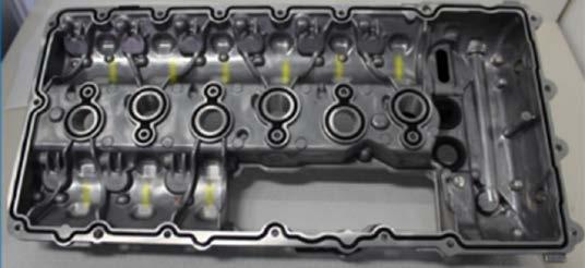
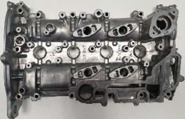
Fig.1 - Components realised, tested and measured (images not to scale each other).
As thin large valve covers regard, one cover was analysed before and after shot blasting: Cover 1 (as-cast) and Cover 1S (cover 1 after shot blasting). The cover was tested only in [311] configuration because of the high numbers of points selected. Massive valve covers analysed were two, and were named after : Cover Basic (as-cast), Cover Evo (as-cast) and Cover EvoS (cover Evo after shot blasting). It is important to note that Evo weights 5% in less than Basic because Cover Basic presents different wall thickness to Cover Evo: Basic wall thickness is 4.5 mm, Evo wall thickness is 2.5 mm. Details about the lighter design are showed in Fig.2-c and d. effect of the shot blasting, that change the tensional state of the point from tensile to compressive state. Moreover, it is also clear that all parts of the cover benefit from the shot blasting, as highlighted for sample Cover 1S in both the line chart and the Debye ring. If the previous stress state is in tensile condition (point 24) or a quasi-tensile condition (as points 1, 12, 17), the shot blasting causes a strong impact on the residual stress changing it into a strong-compressive state.
RESULTS AND DISCUSSION Thin large valve cover One thin large cover was analysed in the as-cast and trimmed state and then after shot blasting. Twenty-four possible critical points were selected where residual stress were measured (as illustrated in Fig.2-a). Fig.3 shown some details about the measurements. Camera image depicts the analysed point. The red-LED marker visible in the figure indicates the analysed point, that must be located as much as possible into the middle of the rectangular-shaped dotted yellow-lines. The Debye ring indicates the residual stress state. As clearly noticeable from Fig.3-a, Debye ring in shot-blasted covers have smoothed edges suggesting a homogeneous stress state. Fig.3-b displayed the line chart for analysis performed on planes [311]. For points 13, 14 and 22 it was not possible to perform measurements in planes [311] because of the shape of the cover. As point 24 regards, it becomes evident the beneficial
Fig.2 - a. Optical analysis in thin cover in as-cast (left) and shot blasted (right) states and analysed points; b. analysed points in massive valve cover; c. Lighter design in massive cover; d. Wall thickness in the massive cover.
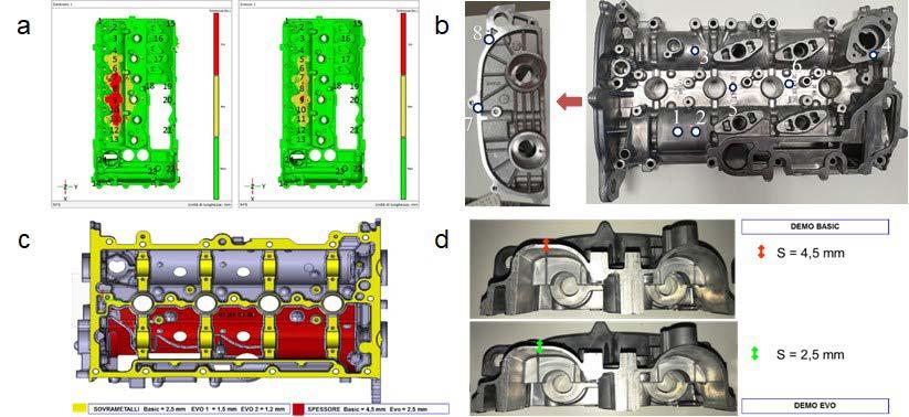
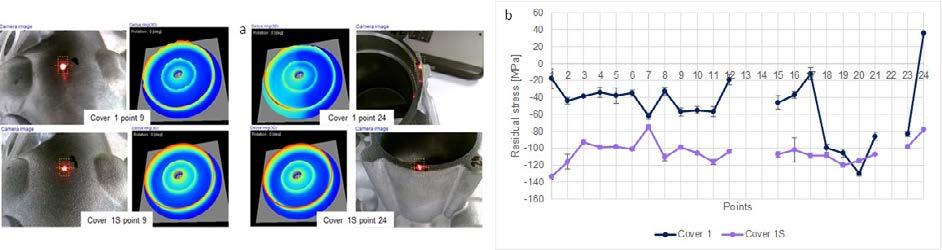
Fig.3 - a. Results obtained for ‘thin large valve cover’ in the as-cast state (Cover 1) and after shot blasting (Cover 1S). Upper images: points #9 and #24: Debye rings and camera images of the referred points. b. line chart of measurements performed.
The shot blasting influences the residual stresses equalizing it along the entire surface. In the as-cast cover, the average tensional stresses values based on all points analysed was -50±36.6 MPa, while after shot blasting the average was -104.6±13.1 MPa. The high standard deviation in the as-cast state was motivated by the strong variations in the measured points: from +36 MPa (point 24) to -130 MPa (point 20).
MASSIVE VALVE COVER
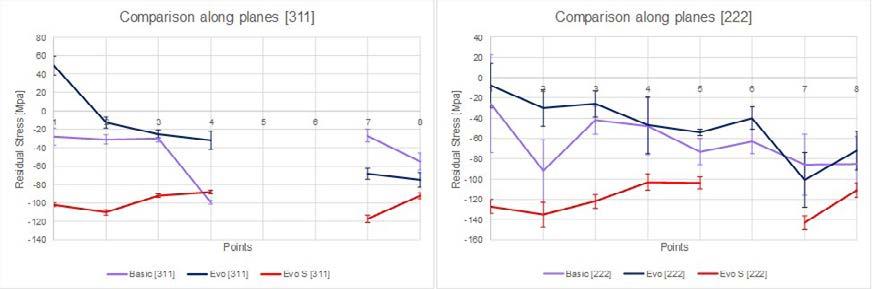
For these covers the wall thickness reduction contributes to weight saving and has an impact on the residual stress state. In Fig.4 residual stresses are shown for both [311] and [222] planes. From the measurements, a compressive state on the surface of Cover-Basic arises, with an average value of almost -50 MPa on [311] planes and -60 MPa on [222] planes. On the other hand, the lightened cover Evo results in a tensile or quasi-tensile state in some parts of the cover surface, with average values of -5 MPa in [311] and -35 MPa on [222]. The lateral points (7 and 8) showed similar tensional state for both Cover Basic and Cover Evo and in both planes. After the shot blasting, a general compressive residual stress results on the surface of Cover Evo S, with average values of almost -100 MPa along [311] planes and -115 MPa on [222] planes. Further considerations can be done: first of all, the
lightened cover (Evo) results in higher distortions and a light compressive state. Secondly, as attended, the shot blasting caused an increase in the compressive state, without residual tensile stress. From Fig.4 resulted that points 5 and 6 were not measurable in planes [311] because the cover shape makes impossible the approaching of the instrument at the correct distance, while in Cover Evo S on [222] planes, measurements for points 5 and 6 were not shown because of the strong distortions detected and/or the high standard deviations. The weight reduction affects the tensional state increasing the possibility of having tensile stresses or slight compressive stresses. In this respect, weight reduction caused the change from the average value of -45±28.5 MPa in Basic cover to -27±48.3 MPa in Evo cover on planes [311], and from -64.4±23.8 MPa to -47.3±29 MPa on planes [222]. The high standard deviation is motivated by the uneven tension state, typical for the as-cast products. On [311] planes maximum value was +49 MPa and minimum value -75 MPa, on [222] planes the maximum value was -8 MPa and minimum value -101 MPa. Since the lighter cover Evo presents tensile stress in point 1, the cover was further investigated in the shot blasted state founding the average values of -100.2±11.5 MPa on [311] and -120.7±15.4 MPa on [222].
Fig.4 -Line charts for Cover Basic and Cover Evo.
CONCLUSIONS In this work, two powertrain components were investigated in terms of residual stresses, in the as-cast and trimmed state and after shot blasting. Referring to the aims of the activity , the main conclusions follow. 1. The X-ray diffraction method (non destructive) can be applied, with some limitation in accessibility to certain area, to complex geometries. 2. The casting geometry (wall thickness) affects residual stresses. Components investigated, reported in Fig.1, are the thin large valve cover and the massive valve cover. Particularly, massive valve cover was investigated in the Basic shape and in the Evo shape, to highlight the effect of the weight reduction on the tensional state. In fact, despite the weight reduction appears as very important for both the fuel consumption reductions and the cost savings, it influences the residual stresses too. As the thin large valve regards, analysis highlight the beneficial effects of the shot blasting that has harmonized the tensional state from the average value of -50.2 ± 36.6 MPa to -104.6 ± 13.1 MPa. Measurements were performed only on planes [311]. In the massive large cover, the analysis performed on Cover_Basic evidenced a compressive state on the cover surface. Furthermore, maximum and minimum values measured in Cover_Basic are -27 MPa and -99 MPa on planes [311] and -26 MPa and -92 MPa on planes [222]. The weight reduction obtained by the thinning of the cover wall, as indicated in Fig.2, caused in Cover_Evo a variation in the tensional state. In this sense, on Cover Evo were documented stresses maximum and minimum respectively of +49 MPa and -75 MPa on [311] planes and of -8 MPa and -101 MPa on planes [222]. From these values appears quite evident the presence of an uneven tensional state more pronounced that in Cover Basic. 3. Manufacturing process steps ( i.e. shot blasting) affect residual stresses. After the shot blasting, the cover presents a different tensional state, with a homogeneous compressive state having -88 MPa as maximum and -117 MPa as a minimum compressive state on [311] planes and -103 MPa and -143 MPa on [222] planes. These results evidenced the effectiveness of the residual stresses measurements, that underlined the impact of the lighter design on the tensional state in castings. Furthermore, the shot blasting process brings uniformity in the tensional state improving the quality of the powertrain components, reducing the possibilities to triggering into fractures during the assembling of the engine components. 4. The X-ray diffraction (non destructive) technology is suitable for in-process quality control to be adopted during new products development phase. In particular portable X-ray measurement to evaluate the residual stresses in the casting parts is a very interesting source for quickly evaluating both the residual stresses due to casting process and the beneficial effect of the shot blasting, allowing the analysis of various shapes of the castings.
AKNOWLEGMENTS The activities described have been undertaken within the ICARO- Project codes: 309/2 and 309/3, in the frame of “IR2” Industrialization of Research Results within the Regional Operational Programme “Regional Competitiveness and Employment”.(E.R.D.F. 2014/2020 Action I.1b.1.1. – “Support for the economic exploitation of innovation through experimentation and the adoption of innovative solutions in processes, products and organisational formulas, as well as through the financing of the industrialisation of research results”) – Legal basis: EU Regulation n. 651/2014.
REFERENCES
[1] Fracchia E, Gobber FS, Rosso M, Actis Grande M, Bidulská J, Bidulský R. Junction characterization in a functionally graded aluminum part. Materials (Basel). 2019;12(21):3475. [2] Lombardo S, Fracchia E, Gobber F, Rosso M. Gestione delle conchiglie nella colata in gravità e possibili vie per migliorarne prestazioni e durata. La Metallurgia Italiana. 2019; 6. [3] Otarawanna S, Dahle AK. Casting of aluminium alloys. In: Fundamentals of Aluminium Metallurgy: Production, Processing and Applications [Internet]. Woodhead Publishing Limited; 2011; 141–54. Available from: http://dx.doi.org/10.1533/9780857090256.1.141. [4] Schajer G S, Ruud C O. Wiley. Practical Residual Stress Measurement Methods. 2013. [5] Kandil FA, Lord D, Fry T. National Physical Laboratory. A review of residual stress measurement methods: a guide to technical selection. NPL Mater Cent. 2001;1–42. [6] Ripley MI. Residual stress measurement using neutrons. Mater Forum. 2006;30:219–24. [7] Fitzpatrick ME; Fry AT; Holdway P; Kandil FA; Shackleton J; Suominen L. Determination of residual stresses by X-ray diffraction. Measurement Good Practice Guide No 52; 2005; Available from: http://eprintspublications.npl.co.uk/2391/. [8] Guo J, Fu H, Pan B, Kang R. Recent progress of residual stress measurement methods: A review. Chinese J Aeronaut. 2019; Available from: https://doi.org/10.1016/j.cja.2019.10.010. [9] Tsakalakos T, Croft MC, Jisrawi NM, Holtz RL, Zhong Z. Measurement of residual stress distributions by energy dispersive X-ray diffraction synchrotron radiation. Proc Int Offshore Polar Eng Conf. 2006;57–64. [10] Schajer GS. Relaxation Methods for Measuring Residual Stresses: Techniques and Opportunities. Exp Mech. 2010;50(8):1117–27. [11] Gur H. Review of Residual Stress Measurement by Magnetic Barkhausen Noise Technique. Mater Perform Charact. 2018. [12] Hosseinzadeh AR, Mahmoudi AH. An approach for Knoop and Vickers indentations to measure equi-biaxial residual stresses and material properties: A comprehensive comparison. Mech Mater [Internet]. 2019;134:153–64. [13] Sasaki T, Kobayashi Y. X-ray multiaxial stress analysis using two Debye rings. Adv X-ray Anal. 2009.


