Tips & Tricks

Also in this issue:



Also in this issue:


Welcome to the Tips & Tricks issue of AUGIWORLD!
I am a big fan of tips & tricks. I love sharing information that helps others in their job. Anything that you can share with your co-workers will help you and your entire team.
Some ideas for sharing information with co-workers:
Setup an internal document that everyone can contribute to (perhaps in SharePoint or a company intranet page).
Hold a monthly internal user group meeting (virtual meetings are fine) and use 10 minutes of the time to share tips & tricks.
Over the years I’ve seen so many CAD/BIM users that have been given a tip and immediately asked me how long the software has been able to do that. Usually the answer is for at least 5 years, but sometimes the answer is 10 or 20 years. The response given is almost always a groan and the software user asks me why they didn’t hear about it sooner.
If you are a solo CAD/BIM user, look for online tips and tricks, make an effort to reach out to people in your software community that can assist, join an online group on Linkedin, Facebook, etc. or read AUGIWORLD
Sincerely,
KaDe
www.augi.com
Editor
Editor-in-Chief
Todd Rogers - todd.rogers@augi.com
Copy Editor
Isabella Andresen - isabella.andresen@augi.com
Layout Editor
Debby Gwaltney - debby.gwaltney@augi.com
Content Managers
3ds Max - Brian Chapman
Civil 3D - Shawn Herring
BIM/CIM - Stephen Walz
BricsCAD - Craig Swearingen
Electrical - Mark Behrens
Manufacturing - Kristina Youngblut
Revit Architecture - Jonathan Massaro
Revit MEP - Jason Peckovitch
Tech Manager - Mark Kiker
Inside Track - Rina Sahay
Advertising/Reprint Sales
Kevin Merritt - salesmanager@augi.com
AUGI Executive Team
President
KaDe King
Vice-President
Frank Mayfield
Treasurer
Todd Rogers
Secretary
Kristina Youngblut
AUGI Board of Directors
Eric DeLeon
KaDe King
Chris Lindner
Frank Mayfield
Todd Rogers
Scott Wilcox
Kristina Youngblut
Advisory Board Members
Shaan Hurley Shelby Smith
Publication Information
AUGIWORLD magazine is a benefit of specific AUGI membership plans. Direct magazine subscriptions are not available. Please visit www.augi.com/account/register to join or upgrade your membership to receive AUGIWORLD magazine in print. To manage your AUGI membership and address, please visit www.augi. com/account. For all other magazine inquires please contact augiworld@augi.com
Published by:
AUGIWORLD is published by AUGI, Inc. AUGI makes no warranty for the use of its products and assumes no responsibility for any errors which may appear in this publication nor does it make a commitment to update the information contained herein.
AUGIWORLD is Copyright ©2024 AUGI. No information in this magazine may be reproduced without expressed written permission from AUGI. All registered trademarks and trademarks included in this magazine are held by their respective companies. Every attempt was made to include all trademarks and registered trademarks where indicated by their companies.
AUGIWORLD (San Francisco, Calif.)
ISSN 2163-7547



This month, we’ll cover some great tips you like using 3ds Max.
Procedural content has been steadily increasing in popularity; nevertheless, incorporating it into a particular project can pose challenges, primarily because of the time and technical investment required for its creation. In contrast, manually generating content may seem quicker; however, workflows continuously improve, allowing professionals to harness procedural workflows more effectively. 3ds Max’s Boolean tools are a great example.
With a spline selected, in the shapes panel, select the drop-down and choose Compound Shapes. Here, you can perform a Boolean operation on multiple shapes, retaining their original shapes
and allowing you to adjust the individual parts as needed. The operation also allows for chamfer and fillets and uses its Boolean explorer to adjust stacking and interaction. See Figure 1.


Next, apply a multi-level bevel modifier to get it some depth and form.
To enhance your object quickly, apply a traditional mesh Boolean with Chamfer, Weighted Normal, and Turbosmooth modifiers. See Figure 2.
Utilizing those modifiers and this workflow allows you to create dynamic and procedural objects that can be easily manipulated throughout any step in the stack. See Figure 3.
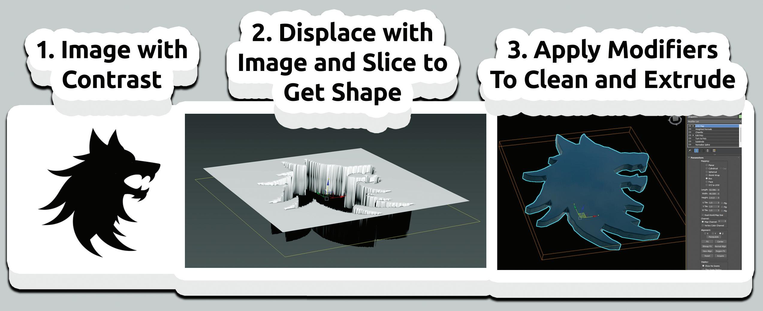
A common task for 3D professionals is to convert 2D images into 3D objects. While most of us have used CAD, Photoshop, or Illustrator to generate those shapes, 3ds Max has an interesting approach worth considering. By applying a Displace Modifier to a plain with a high subdivision level, we can slice it in the center and extract the shape. After adding the displacement, add an Edit Poly modifier, press three after the slice (this will automatically select the cut), and extract the shape from the panel options. See Figure 4.
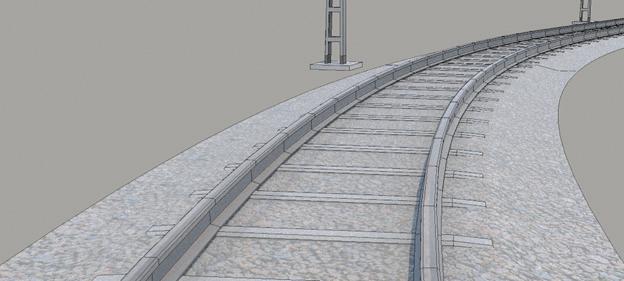
Rail Clone has been around for several years and offers a free lite version. However, many don’t know how powerful it is. If you like the procedural spline-based mesh generation in software like Unreal Engine and Unity, you’ll like Rail Clone. It offers similar and powerful functions to generate procedural, path, and spline-based content quickly. It’s excellent for building everything from stadium seating to sidewalks and castle walls. See Figure 5.
Innovation with 3ds Max is found by creating intelligent ways to combine modifiers to produce work quickly. The example below demonstrates
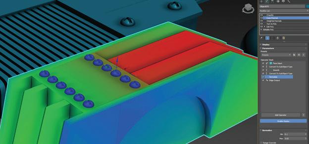
one way to do that: combining the Data Channel modifier with the Chamfer modifier weighted property to control the level of chamfer for macro and micro details on an object. See Figure 6. To see that in action, visit the video linked here: https:// youtu.be/mDMNnOczWds?feature=shared

Brian Chapman is a Las Vegas 2D/3D design professional who creates content for the AEC industry, games, film, entertainment, and software development. Brian can be reached at procadman@pro-cad.net.


When I think of the talents that a Tech Manager needs, one that is always at the top is customer service. I know I have written about it before and after this article, I will most likely write about it again. It is the talent most needed, other than tech skills, by those we support. They want excellent customer service. So here are a few things to keep in mind, set in the context of good service at a resort, hotel, or restaurant.
Provide “Room Service”. Give support to your staff. No one wants to leave their hotel room if they are settled in and need something. A toothbrush, a snack or a full dinner. It is nice to order and have it brought to you. Doordash, Grubhub, or whatever, entire industries have popped up that deliver ready-to-eat meals, so you don’t have to get up and go out. Don’t make the staff always come to you. Just like a late-night delivery of room service to your hotel room, providing support to the staff is important. I suggest just walking around. It gets
you out of your chair and up to where the action is. Walking around allows the staff to see you and ask questions when they would not get out of their chair and try to find you. Move around a little and mingle, but don’t linger and interrupt workflow. Listen as you walk. What are folks talking about? You are just passing through, but offering support as you go.
Shorten your Message. You hear a knock at the door, “Room service”. With that quick announcement, you have all the info you need. Your food has arrived. The message is short and to the point. You need to keep your messages short and to the point. I am a “bottom line up front” kind of guy. I get to the point quickly and I think people appreciate it. When delivering support or training, I try to get the needed information out without a lot of fluff. When people need help, they need to get back to work quickly. They usually don’t want a lot of discussion, unless they ask. I usually stop after I give the needed info and ask if they want more.
Some people like to know why things happen and other couldn’t care less, they just want to get back to work.
Simplify your Message. And while you are keeping your messages short, keep them understandable also. People usually do not want to hear the tech details (unless they ask). Give it to them in simple terms and eliminate the long techno focused explanations of the problem and the fix. Just give them the non-tech reasons and offer more if they want it. “There was a problem with the server, it was nothing you did.” If they want more, tell them the issues that the server was having and the fix it took, but keep that uncluttered also.
Serve Everyone at Once. One year, when I was at AU in Las Vegas, the firm I worked for sponsored a dinner for the staff that was attending. The menu was a selection of chicken, fish or beef and each person selected what they wanted. There were about 10-12 people at the table. The food was prepared and delivered all at once. I mean it was choreographed. Six wait staff brought two covered dishes each, set them all down at once and then uncovered them at the same time, with a flourish. It was a sight to see, and every person got the right meal in front of them. Excellent theatrics and superior customer service. I don’t remember what I ate, but the service was fantastic.
You obviously cannot be everywhere at once, but you can help everyone at the same time. You can do this by communicating with the entire staff via email, text, chat or whatever. Just let everyone know. Whatever you are sharing with one person, share with all. It is true that some will not read or listen, but you should share it with all. You may want to offer to share tech tips at general meetings if appropriate. Just get the word out to everyone.
Give away Something for Free. At a resort, it might be as simple as a mint on a pillow, or water dispensers by the pool, or a cookie at check-in, but giving something unexpected for free is always appreciated. In tech support, this is a tip, a trick, or an improvement. When you help others or fix a problem, share some tips related to the area of concern. You may even ask them if they have a tip to share. You could mention something you read about or something other team members have shared with you. It may just be a short conversation on new tech. Team members may like to discuss upcoming tech trends.
Be Available. No one likes wait staff that seems to make it hard to flag them down. Have an opendoor policy and make yourself available to everyone. Make it easy to connect with you. It could be an online ticketing system, or just a text message. Take support needs any way they come at you. Don’t constantly remind people to only use one method. Sure, you can encourage ticketing systems, but most staffers do not really like them. They are too cumbersome. Make it easy to get a hold of you.
Offer Self-Serve. Like the free morning coffee bar that some resorts offer, you could have a self-serve online knowledge base with searchable “how-to” articles. Let the staff find support for themselves. When you fix a problem that has been popping up around the office, write up an article and post it.
Would you like anything else? At the end of a good meal, you are usually asked if there is anything more you would like. When the immediate support needs are done, ask them if they need anything more. Maybe circle back later and ask. It lets staff know that you are willing to do more if needed. They can always come to you.
Many of these may be common sense, but it is the consistency you bring by remembering to do these things on a regular basis that helps others see your customer service focus.

Mark Kiker has more than 35 years of hands-on experience with technology. He is fully versed in every area of management from deployment planning, installation, and configuration to training and strategic planning. He is an internationally known speaker, writer and former AUGI Board member and president. Mark is currently serving as Chief Technology Officer for SIATech, a non-profit public charter high school focused on dropout recovery. He oversees two web sites, www.caddmanager.com and www.bimmanager. com. He can be reached at mark.kiker@augi.com and would love to hear your questions, comments and perspectives.

Working with complex drawings can be a real challenge, especially in a fast-moving world like today, where productivity is key. Having easy-to-use and efficient CAD software is a crucial requirement for increasing your productivity. What if CAD software not only meets these criteria but also seamlessly integrates into your workflow without causing any disruptions? That would be even better.
Let’s dive into some of the many tips and tricks that BricsCAD® offers for drafting.
In this article, we’ll guide you through some of the key benefits of BricsCAD® and show you how to use them to your advantage. We’ll explore some of the unique BricsCAD® features that help you streamline your workflow. With these features, you’ll not only elevate the performance for heavy drawings, but you’ll also make sure the drawing accuracy is at its highest. Go from design to deliverable in record time and enhance your user experience by using the BricsCAD® innovative features.
SIMPLIFY – this unique BricsCAD® command is a drawing optimization tool that simplifies polylines, splines, and non-associative hatch boundaries by reducing the number of vertices, without changing their general shape.
Drawings originating from scanning devices can sometimes contain far too much detail to handle in double-precision CAD systems. With this command, the common vertex between two consecutive segments can be removed, or consecutive straight segments can be replaced with a bulged polyline segment as long as the endpoints lie on an exact arc. (See Figure 1)
After they’ve been simplified, entities are easier to manipulate, and the drawing file size can decrease significantly.
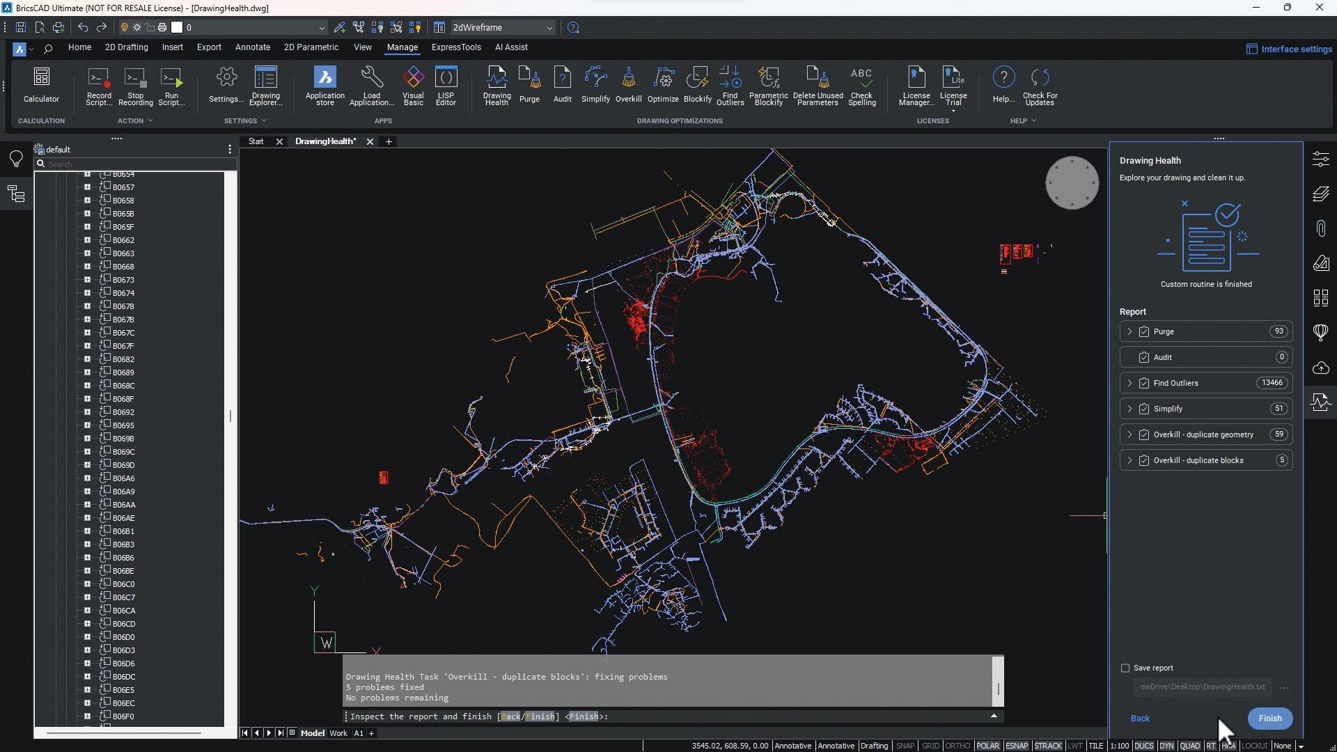
DRAWINGHEALTH – combines the power of multiple stand-alone BricsCAD® commands in one place. BricsCAD® offers multiple drawing optimization tools, and when dealing with complex drawings, manually operating these tools for cleanup can be time-consuming.
With this BricsCAD® unique drawing optimization tool, Drawing Health, you can create routines and have all these tools in one place and ready to go with just a few clicks. You can reduce the drawing size, remove unused styles, entities, and layers, and improve the overall drawing quality.
Routines save commands, settings, and preferences and can be used on other drawings. You can use or edit one of the routines available by default, or you can create new ones, according to your needs. You can choose between commands such as Purge, Audit, Find-Outliers, Simplify, DMAudit, Overkill,

Blockify, and Array-Detect. Upon initiating a routine, the command context panel provides a clear overview of the tasks it will perform. Interactive mode switches to manual checks and fine-tuning for each task. Following the completion of the last step of the routine, a report of the cleaning up of the drawing will be displayed. (See Figure 2)
FITLINE/FITARC/FITPOLYLINE – fits lines, arcs, circles, or polyline to entities.
BricsCAD® includes a set of tools that assist users in the process of manipulating data sets and provide relevant geometry to a drawing. These commands work with any input entity type, so they can be applied to various use cases.
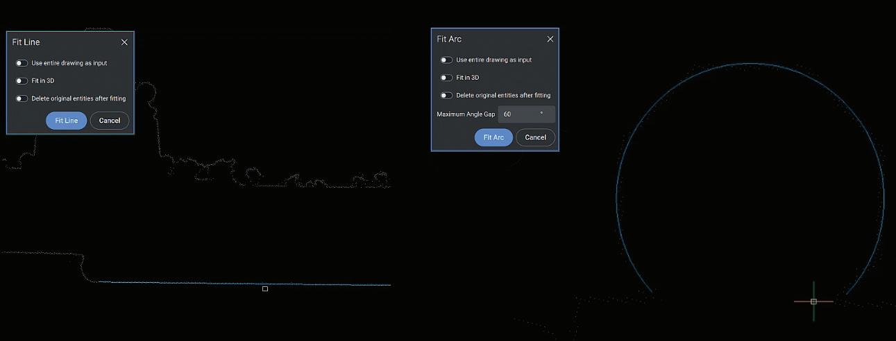
For instance, when dealing with a large amount of data stored in the drawing in the format of points, these unique BricsCAD® tools may come in handy for you to be able to draw accurately.
FITLINE fits a line to one or more entities, while FITARC fits an arc or a circle to entities. When one or more input entities do not lie in the XY-plane, simply check the Fit in 3D option within these commands, and the resulting line will be created in 3D space. Otherwise, the input entities are projected onto the
XY plane first. The XY-plane used for projection is one of the current UCS, which allows the user to make the fit in any plane (See Figure 3).
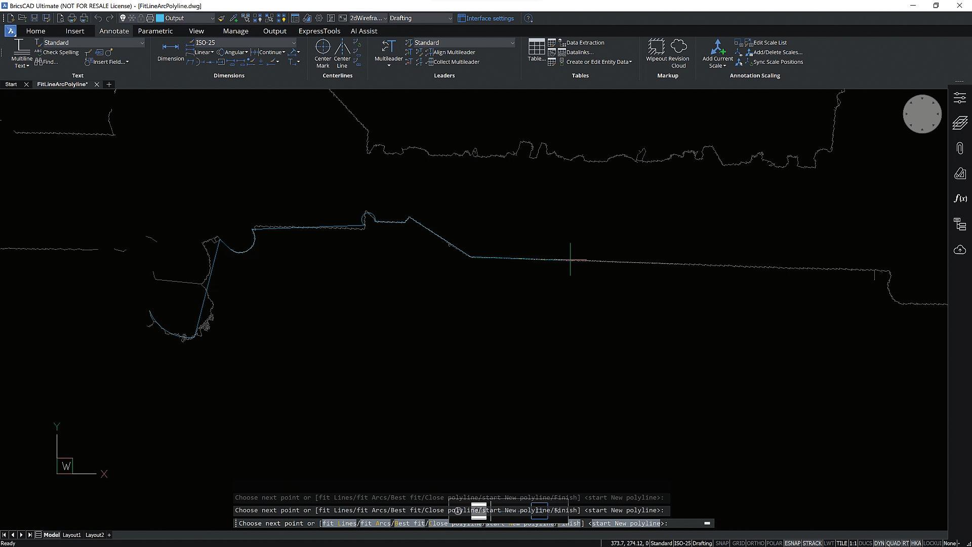
FITPOLYLINE draws one or multiple polyline entities, fit to the characteristic points of the input entities. The advantage when using this command is that the algorithm automatically decides whether a linear or an arc polyline segment is best suited to fit the points between the last fixed polyline vertex and the mouse position. (See Figure 4)

The MANIPULATOR – a versatile grip tool, that allows you to swiftly move, rotate, scale, and mirror selected entities. With this visual tool, you’ll benefit from dynamic movement, rotation, mirroring, and scaling of selected geometry, without any command input. Using it is far more convenient than using a combination of other functions, such as MOVE or ROTATE, especially when it comes to multiple manipulations (See Figure 5).
The Manipulator is intuitively easy to use, and, used in conjunction with direct modeling tools, it can be a powerful way to model shapes. Using this tool, you’ll have standard displacement commands right at your cursor. You can work with single objects or with groups
of entities at once. Its anchor point can be moved as you wish, giving you more control over your design.
The Manipulator has multiple trigger zones: you can click on the axes to move an entity, on the arcs to rotate, the arrowheads to mirror an entity and you can even do plane swatches to move freely in the selected plane.
When starting the action, holding down the CTRL key will keep the original entities, creating copies. Some of these actions will also display a ruler, of which increments change dynamically (See Figure 6).
This means you can work accurately at any scale, and you can easily copy items during a rotate or move command. This capability enhances your workflow, allowing you to work quickly and precisely in the way you need to.
– speed up your work by pairing these tools up and using them as an alternative to the command line, toolbars, or properties panel.
The BricsCAD® Quad is a context-sensitive graphic menu that offers a rich set of tools, which is dynamically displayed at the cursor. It uses entity recognition and gives suggestions based on the most relevant and frequently used tools according to the active workspace and the entity you hover over (See Figure 7).
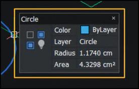
On the other hand, the Rollover Tips feature displays a selection of entity properties in a popup box near the cursor when hovering over or selecting an entity (See Figure 8).
Though these features are independent, pairing them together will make a powerful duo. Level up your user experience using these intelligent tools which offer a


set of functions in the context of the cursor’s selection. This not only makes your design processes more efficient but also cuts down your working time and helps you keep your workspace clean. Not to mention that their content is fully customizable!
AI ASSIST Ribbon tab – helps you work smarter and more efficiently by providing suggestions based on your personal BricsCAD® usage, and similar users. To unlock this intelligent feature, simply sign up for the BricsCAD® Analytics Program. With BricsCAD® Analytics Program you can get access to improved and personalized features to meet your individual needs and unlock the smart AIdriven ribbon. Once signed up for this, the AI Assist ribbon tab immediately populates and suggests the commands you will likely need next based on your workflow patterns and typical behaviors – helping you save time! (See Figure 9)
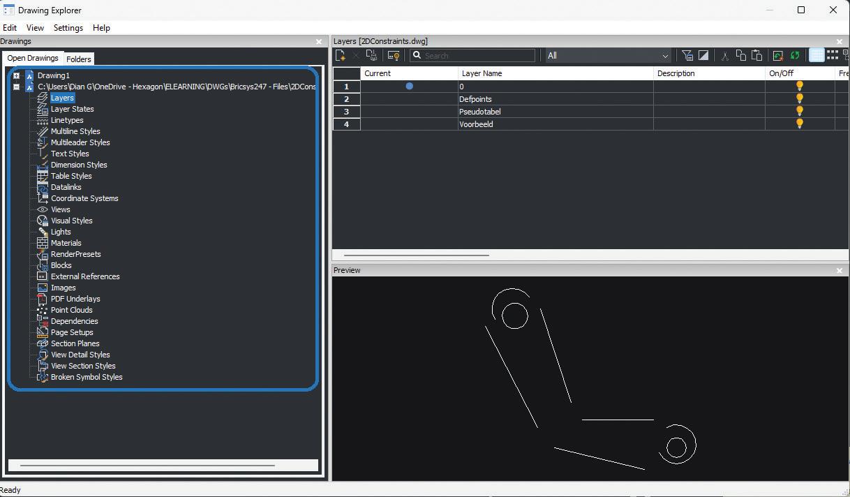
BricsCAD’s® Drawing Explorer offers a simple tool for comprehensive drawing management. This
powerful tool provides a fast and effective way to perform a range of essential functions in one place. The Drawing Explorer enables all the key aspects of a drawing to be managed in one singular and comprehensive place, providing good visibility of the properties within a drawing. Here, you can configure dimension styles, layers, text styles, and more (See Figure 10). You can also manage multiple drawings in one place, by simply copying definitions between drawings. With Drawing Explorer, you’ll have better drawing management. Your work will be more effective, and your project drawings will be more consistent.
Whether you are a beginner or an experienced user, BricsCAD® provides a rich set of tools to help you complete your projects on time. Don’t take our word for it- see it for yourself. Download a 30-day BricsCAD® trial now and give these tips and tricks a try. And if you’re hungry for more, rest assured that the Bricsys teams are working tirelessly to ensure our users have continuous access to valuable knowledge in CAD drafting.

Bricsys® BricsCAD® is professional CAD software without compromise. Accelerate your time to deliverable without compromising on performance, cost, licensing flexibility, and data security. Not ready to buy? Download the free, 30-day trial of BricsCAD® at Bricsys.com. Would you like free lessons? We have that available with Bricsys Learning. Ready to migrate to BricsCAD®? Download the Migration Guide. The latest version of BricsCAD® improves the tools and features users love, as well as new functionality and UI that supercharge productivity. Follow us today on LinkedIn or YouTube
Bricsys®, part of Hexagon®, is the global technology company that creates the BricsCAD® family of computer-aided design (CAD) products and the Bricsys® 24/7 project collaboration platform. We are relentlessly committed to the success of our customers by offering cost-effective, missioncritical CAD software with industry-leading product support. Learn more at www.Bricsys.com.
Hexagon is a global leader in digital reality solutions. Learn more about Hexagon (Nasdaq Stockholm: HEXA B) at hexagon.com and follow us @HexagonAB.

Ms. Diana Gagiu is the Learning Manager at Bricsys. She started working at Bricsys® as a Technical Support Specialist and then worked as a content creator for the eLearning project. Currently, Diana is dedicating her time to the eLearning project only, making sure BricsCAD’s® users have quality learning materials to learn from. She is very passionate about her job and proud to be part of Bricsys®. Before working at Bricsys®, Diana studied Chemical Engineering at the Politehnica University of Bucharest.

What are the real-time challenges and issues that you must manage when trying to establish CAD standards and training in a hybrid office environment?
Developing CAD standards, and the implementation thereof, are challenges unto themselves. The training of CAD users, although a separate activity, must be coordinated with CAD standard development and implementation.
Without a plan that encompasses both challenges together, the best efforts and intentions will ultimately fail. Getting buy-in from management is usually challenging enough. Minimizing the chance of failure is in your best interest early in the process.

How does the hybrid work environment affect your efforts?
Having a hybrid office attendance policy creates a whole new dynamic. You will need to rethink your plans and how to successfully implement them. The WFH (work from home) option for many offices now embrace is both a blessing and a curse at the same time.
The unavailability of personnel, be it for daily work activity or the ongoing development of personnel and their training, will, unless well managed, be an issue. I realize that I am not saying anything that has not been discussed at length already.
Your first challenge comes when management looks at the potential ROI (return on investment) they will see from your proposed plans. They are very aware of the challenges that WFH policies bring, and the inefficiencies that come along with these challenges.
As your standards and training plans will require at least some time together in person to be productive, you will need a solid understanding of how to efficiently plan for the various types of activities that you need to handle.
All Invested people will need to be available when developing processes and discussing plans that will affect them (or their direct team members). Not having all your key personnel available to establish and discuss activity that will affect not only the invested people but potentially the entire company, can create delays.
Meetings will by default become more challenging to coordinate the higher the attendee count, and scheduling online meetings makes things more complicated.
While online meetings are an option and a viable alternative to in-office attendance, the availability of personnel when WFH is often not ideal. People will adjust their work schedules to accommodate family activities as required. As anyone with kids will tell you, schedules are fluid.
One person may work their time during the day to fit their schedule, while another works in the afternoon or evening. Both people are legitimately working. However, trying to get them both into a required meeting together can be a challenge.
Accommodating multiple people’s schedules when they potentially conflict is a bit of a dance yet has become the new normal in business today.

The inclusion of key players in early Planning and research is critical to the successful integration of hybrid work cultures and standards implementation.
Standards and training will by default require research and establishing a plan of action. The real challenge comes with the unavailability of key people, due to either working from home or being so buried in work because they are the only people available to handle the in-office concerns.
As schedules and timelines will vary between people, there will need to be a solid plan for communication between the WFH group and the in-office personnel. This will require all the key players to be vigilant in keeping up to date on recent activity. Do not be surprised when this is the hardest part of the challenge.
Establishing an online messaging system (chat group or similar) to provide real-time access for all involved parties becomes a basic requirement. This will provide a way to allow people with different schedules to share their concerns easily.
Management, however, will want some justification for the hours charged for this activity. A dedicated time for all parties involved to meet (online is easiest) should be regularly scheduled with management in attendance. This will achieve several things. First is that management will get a good feel for the team’s progress. Additionally, management will be reliably available to the team members.
Management, for their part, is interested in the ROI of standards and training. That is the language they speak ($$$$). People being remote or in the office is secondary to them. It will be up to the people responsible for establishing the standards and training to get the details right. Remember, their first impression of your proposal is what will be remembered.


Good planning and inter-team communication from the start will set up a smooth road to travel as you move forward. Stick to your plan and be ready for the unexpected to come up. Do not let a detour or roadblock dissuade you from your goal. Even with teams that are working in different locations there can and will be success if you keep pushing forward!

If I could tell you what would work in your specific situation, I would certainly do so. The reality is that each organization has its own set of challenges. The investment level of management in organizing and creating a workable plan will determine your best path and plan as you move forward.
If upper management is supportive of the drive to develop a corporate protocol, the efforts of mid-level managers will have a better chance of gaining traction. As a CAD manager, you are likely to be tasked with developing training procedures and supporting standards in this role. Your first concern will be getting people together in person. This builds a sense of teamwork among people. Without a team mindset, WFH employees will often see no reason to work on developing any plans or practices that are outside of their interests. The WFH policy has reinforced the perception that one does not need to collaborate with others for several years now. People are more open to change and working together towards a common goal when a real result is evident and they, as individuals, feel valued in their participation.
The core values of standards and training have not changed with the upheaval of the working environment. Corporations will still need to develop standard protocols. Your CAD operators still need training.

You, however, will need to rethink the methodology that is used to implement these goals. When you have limited time available in which to propose a new process, or train people, efficiency is key. You need to fine-tune your approach, incorporating all the tools you have available.
Determining what can be best accomplished remotely, yet effectively is now your priority. Training of CAD operators is possible remotely; however, not efficient or as productive as in person. Getting a clear picture of the mindset of those you are teaching is critical to being successful. Power users (mentors) and experienced people will be obvious and become valuable training partners. Train first in person and provide a support online chat for users to communicate afterward.
Establishing standards (protocols) that are driving corporate-level activity is another thing. Online meetings are quite functional for this. As things get defined, reduce the number of attendees and work on details. Things that can be explained in a

document are easily handled online (remote users will not be interrupted from their work) at much less cost in time and resources.
As a last thought, I leave you with this; CAD standards and operator training will come down to the people you work with. Some will follow quickly, some not so. Your corporate standards and operator training must be adaptable, flexible, yet focused effort. It will evolve with the working environment and your co-workers. Feel free to fail, usually multiple times. You get better by learning from mistakes and not giving up when things do not go as planned.

My current employer designs Automated Guided Vehicles (AGV’s) and test machines. I have worked with AutoCAD software for forty years, starting on version 1.4. Having been with my current employer for almost sixteen years and CAD manager by necessity for at least ten, I have seen their culture change many times in attempts to improve processes and become more efficient. CAD standards have become a high-profile topic recently. I am excited to share my process of implementing a user-friendly system of CAD standards with others.

Today’s fast-paced world of design and construction is fractured. Risk aversion, shortened construction timeframes and more complex projects are creating a gap of information between what was designed and what should be built, costing time and money.
At Walter P Moore, our solution is to solve design virtually, by producing a Building Information Model (BIM) at Level of Development 400 (LOD400). By broadening design to anticipate construction issues and delivering a fabrication-ready model, we can create more certainty in cost, schedule and design intent.
Nearly 50 years ago, Boyd Paulson created a simple yet powerful rubric for understanding the relationship between the influence of decisionmaking for project outcomes versus the committed project costs. The following holds true for every project every time: over the course of the project schedule, the influence to change outcomes
steadily decreases, and the committed project costs go up. Refer to the image below.
We supplement Boyd’s analysis: at any point in time, the final cost of the project is an uncertain/ unknown. It’s estimated, but it won’t be known exactly until the project is complete. It is this uncertainty that is the breeding ground for risk, unmet cost and schedule expectations, and loss of trust between project partners.

One way to combat this problem is to improve the shape of the influence curve. If we can maintain a higher level of influence over project outcomes and hold off on the committed project costs, this is a way to ensure the final cost and schedule better aligns with initial estimates. This white paper will discuss a method to improve the shape of the influence curve.
Over the past 10 years, a number of AEC industry stakeholders have contributed to the development of a common language for BIMs used with increasing frequency and reliance in our industry. The BIM Forum publishes annually a Level of Development (LOD) Specification that provides guidance on the expectations of the BIM for the project. This is performed by applying a numeric value to specific components within the BIM based on the specific criteria those elements satisfy. In general, the higher LOD numeric value, the further along that element is on the spectrum from concept to fabrication-ready.
This common language helps reduce barriers to understanding the nature of the BIM, and therefore increases confidence and the right level of reliance by those who need the information in the BIM to construct the building.
In this white paper, any references to LOD400 will be a reference to the definition provided by the BIM Forum (2021 version quoted): “The Model Element is graphically represented within the Model as a specific system, object or assembly in terms of size, shape, location, quantity, and orientation with detailing, fabrication, assembly, and installation information. Non-graphic information may also be attached to the Model Element.”
Here also is the common language interpretation, also from the LOD Specification: “An LOD400 element is modeled at sufficient detail and accuracy for fabrication of the represented component. The quantity, size, shape, location, and orientation of the element as designed can be measured directly from the model without referring to non-modeled information such as notes or dimension call-outs.”
It’s clear from the definition LOD400 represents elements that are fabrication-ready. All information sufficient to fabricate the element is contained in
the modeled element. This exceeds the Level of Development of a BIM element universally accepted by the design industry as acceptable for permit-level documents. The modeled elements are not merely sufficient for bidding, procurement, or mill order. The modeled elements are ready to be fabricated.
A snapshot of the industry today shows that different building elements are advanced to various LOD endpoints prior to fabrication. Further, certain structural elements (reinforcing steel, for example) are frequently not even modeled before they are fabricated:
• Structural steel: estimated greater than 90%modeled before fabrication
• Rebar: estimated 10% or less modeled before fabrication
• Light gauge steel: estimated 5% or less modeled before fabrication
Why the disparity? We speculate this is due to necessity being the mother of invention. For each structural material, the specific elements themselves benefit variably from an LOD400 in order to be fabricated. For instance, connecting a steel beam or brace to a steel column benefits from all the specific elements (the beam, the column, the connecting plates, the welds, the bolts) being modeled to a fabrication level. Conversely, specific pieces of reinforcing steel do not have such demanding connectivity requirements (or frequently zero connectivity requirements), and therefore there is little advantage gained per bar by modeling individual bars versus fabrication based on a 2D bend diagram drawing.
“First order benefits” are those that provide value to the single trade or structural material directly. We’ve discussed one already: determining intratrade connectivity requirements.
To understand other benefits, let’s discuss 2 examples:
1. Bringing the structural steel to LOD400 yields the first order benefit of preserving design intent. A structural steel frame used as part of a new baseball stadium will be exposed to view in the permanent condition. Therefore, multiple

The Louis Armstrong Airport Expansion featured a highly complex, radial grid system design. It was our task to create a geometry for the form’s structure that was logical, easy to construct and as efficient as possible in a hurricane-prone environment. Using LOD400, connected with a common digital platform bridging skin and roof design, allowed us to work alongside the architects to create a variety of design iterations to better understand ideas from a visual perspective, materials and quantities cost. We were able to preserve the architects’ intent to evoke the Mississippi River’s curves through undulating canopies and curved glass walls.
stakeholders (the owner, architect, sponsors) will care about the aesthetics of the frame: its columns, beams, braces, and connecting elements. Bringing these elements to LOD400 will give these stakeholders a realistic and comprehensive understanding of what these elements look like as well as the ability to iterate/ adjust them through the design process. This process allows more control over the design intent of these elements and minimizes the risk that the final product will not align with this design intent. There will be significantly reduced uncertainty by the steel fabricator for what is required to satisfy the design intent and provide the owner what they expect to see once the project gets built.
2. Building virtually at LOD400 yields the first order benefits of revealing accurate levels of complexity and reducing risk during construction. A new high rise utilizes concrete shear walls as the lateral load-resisting system, arranged around the elevator bank in the central
core of the building. Such shear walls will have elevator and MEP openings at nearly every level. The wall areas around such openings, including the link beams over the elevator openings, are typically among the most complex and congested areas of reinforced concrete on the entire project. An LOD400 model of the reinforcing in this area yields a better understanding of this complexity, and therefore provides more opportunity to plan for how to manage it once the project goes physical. Furthermore, modeled reinforcing will immediately reveal if the area is too congested (i.e. if bars are clashing with each other) and can serve as a platform for resolving such problems. This process of figuring out the project will happen either way: either in the field, or, preferably, in the model. When it’s in the model we call this process “virtual construction.” In this case, bringing the reinforced concrete to LOD400 yields two first order benefits: revealing an accurate level of complexity to the work, and providing an opportunity to perform virtual construction (which is less expensive, faster, and less risky than physical construction).

Virginia Commonwealth University opened a 1 million SF Adult Ambulatory Care Facility, a highly complex structure with elaborate medical equipment atop a parking garage. The building’s complexity required us to accurately solve the design virtually, resulting in a construction process with very few field issues.
“Second order benefits” are those that provide value to multiple stakeholders beyond the single structural trade. In these cases, in combination with other adjacent services on the project, the combined impact of an LOD400 model yields arguably greater advantages to the sum of the stakeholders than the benefit to the relevant trade. Specifically, when the creation of an LOD400 model occurs as an overlay of the structural design, several benefits accrue to the team.
Traditionally and per typical contracts on the design side, the Engineer of Record only needs to issue
designs for these and indeed any portion of the structure, at such a time as when they are prepared to affix their seal to their design documents. Now, whether that is consistent with a presumed construction schedule, prepared and managed by others, is uncertain.
But the issue is, the owner cares about the schedule. It’s one of 3 essential values to the owner of any project: the design, the cost, and the schedule. And the pace of project schedules is only going one direction: faster. The shorter the project schedule, the more chance that a disconnect in the design and construction activities will not just appear but become problematic and sometimes intractable. This is the breeding ground of additional cost, schedule delays, unmet expectations regarding the final outcome, and, many times, litigation.
Time is such a precious commodity that it is hard to imagine project schedules slowing down. Therefore a solution must be found that reformats project delivery in to something that looks different than the past. How can an LOD400 model help?
This is related to the first benefit, but is slightly different. When a structure has been brought to fabrication level, it represents a form of “virtual construction.” When the requisite technical expertise has been brought to bear (engineering, constructability, etc.), then the end product LOD400 represents the “first construction” of the project. And because it’s been done in a virtual environment (where the structure can be moved, supplemented, or even wholesale deleted), it is dramatically less risky to work through “figuring the project out” in this way, versus in the physical environment. No one wants to show up on a job site where objects are clashing with each other. This is a recipe for disaster in terms of time, money, re-design, and the like.
Simply put: it’s possible to overlay the creation of the LOD400 with the development of the design. And because in many cases an LOD400 will form the basis of the fabrication, it represents at some point a step on the critical path of the project. Therefore, starting these activities earlier in the project schedule allows them to end earlier in the

Q2 Stadium, a Major League Soccer Stadium in Austin, opened in 20 months – the fastest project schedule ever completed in MLS. Because of our process, the builder was able to issue a steel fabrication model when the design was 50% complete. This allowed them to have steel delivered on-site more than three months faster than a traditional process.
project schedule. The time savings drops to the bottom line.
When the structure has already been built once, the team has greater certainty on how the project will proceed the second time, i.e. the “physical twin” of the structure. This is what we mean by reduced risk to the schedule – the entire team has greater certainty in the schedule once the project goes physical.
Our firm’s experience indicates that for the large majority of projects, certain aspects of the structural design are known, or at least can be known, earlier in the project timeline than others. Infill composite
We delivered steel procurement documents well before schematic design completion for Virginia Commonwealth University’s Adult Outpatient Pavilion, putting the project 12 months ahead of schedule and saving the owner more than $600,000 in construction costs.
steel beams and pad footings supporting gravity columns are two simple examples of elements we can build first virtually to add speed to the schedule.
As a general rule, the greater the unknowns that exist on a project, the increased number of assumptions contractors and subcontractors need to make when preparing their bids. The project is open to more interpretation. Sometimes this can be beneficial, such as when a subcontractor conceives of a novel way to develop the means of construction. The resulting winning bid provides value to the owner. But whatever advantage exists by leaving certain elements up to the subcontractor to figure out is more than offset by the risk that the design intent hasn’t been understood by those who need to execute it.
However, if trade partners are provided an LOD400 model they can use to prepare their bids, the volume of information that they can use to inform

Ordering steel is the riskiest part of a large-scale job, but Walter P Moore’s complete modeling of GEODIS Park, Nashville’s new MLS Stadium, allowed the contractor’s six steel bids to come in as much as seven figures below the original steel budget, putting millions of dollars back into the project’s bottom line.
their price and schedule increases substantially. There is very little room for misunderstanding design intent. Quantities and level of complexity can be understood readily from the model, sometimes through automated queries. As a result, there’s less risk that the low bidder has missed an important piece of the scope that will eventually need to be part of the built project, or that the high bidder had cost or schedule to cover a piece of scope that wasn’t actually required.
Creating a model at LOD400 has benefits to the structure long after construction. Facility managers can use the information within the model to more accurately space-plan to create the best use of space available, which can aid in real estate expense efficiency. Additionally, the level of detail provided in LOD400 can aid in asset management of building equipment and systems through planning regularly scheduled maintenance, durability and life cycle management.
As we have discussed, today’s projects are moving at a faster pace, with more complexity. While creating an LOD400 model may seem at the outset to increase costs and time spent in design, the benefits have proven time and again to outweigh
these issues, providing significant cost and schedule savings along with reduced risk.
1. https://www.danieldavis.com/papers/boyd.pdf
2. https://bimforum.org/wp-content/ uploads/2022/02/LOD-Spec-2021-Part-IFINAL-2021-12-28.pdf
3. https://www.linkedin.com/pulse/what-benefitsmodel-based-steel-detailing-detailing/
4. https://bimcorner.com/what-is-virtual-designand-construction/

Stephen Blumenbaum, P.E., S.E. is a Senior Principal and the Director of Construction Engineering at Walter P Moore with more than two decades of experience in structural engineering, analysis, and project delivery. He is an accomplished problem solver who blends creativity, technical acuity, and passion with a pragmatic perspective to create memorable, affordable, and buildable one-of-akind structures. He is also a firm leader in leveraging digital workflow solutions to improve the efficiency and quality of work.
Additionally, Steve is an expert in a wide range of market sectors including aviation, commercial, convention center, cultural facilities, entertainment, healthcare, hospitality, industrial, science and technology, and sports. He leads an international team of specialists who provide comprehensive services that seamlessly blend the engineered structure with efficient and safe construction processes. To create client value, he carefully plans his project approach, re-imagines project deliverables using the latest technologies and infuses elegant structural solutions with constructability as a design criterion.

Navigating the Digital Blueprint: MEPF Revit Tips and Tricks for Daily Use
In the dynamic world of MEPF engineering, professionals are continually seeking ways to optimize workflows, expedite project delivery, and unlock the full potential of Revit’s formidable toolset. Whether you are a seasoned MEPF expert looking to elevate your proficiency or a newcomer navigating the digital landscape of building services, this article serves as your compass to navigate the intricacies of Revit, offering 10 tips and tricks that you can seamlessly integrate into your daily practice.
Learning keyboard shortcuts in Revit is straightforward and can significantly enhance your efficiency and speed in design tasks. These shortcuts are also customizable. To access the Keyboard Shortcuts Dialog for customization, simply type “KS” when no commands are active, and the following dialog will promptly appear for you to make your adjustments.
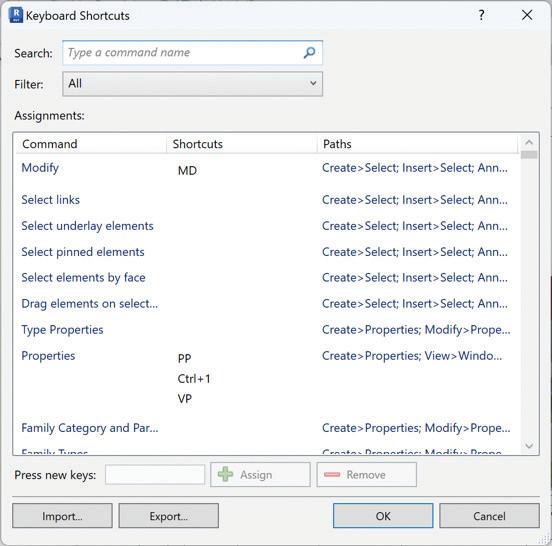
Autodesk has also developed a great Keyboard Shortcuts Guide with a lot of commonly used shortcuts already compiled for you. Just simply search for Autodesk Revit Keyboard Shortcuts using your favorite search engine. The first link you find should take you to a website that contains the following:

Just click on Revit Keyboard Shortcuts PDF to download, open, and print if desired.
To take things a step further if you had a mouse with multiple buttons, you could program those buttons to specific commands/keyboard shortcuts in Revit from manufacturers like Logitech, Razer, Corsair, HyperX and ASUS to name a few.
Revit Tool Tips are a feature in Autodesk Revit, a Building Information Modeling (BIM) software. These Tool Tips provide quick, contextual information about tools and features within the Revit interface. When you hover your mouse over a tool or option in Revit, a small window appears, displaying a brief description of that tool or feature. This is designed to help users understand the function of various commands, buttons, and settings without having to leave the workspace or refer to external help resources.
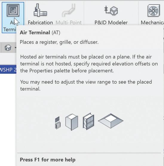
The information in a Tool Tip usually includes:
• Name of the Tool: The official name of the tool or feature.
• Brief Description: A concise explanation of what the tool does.
• Shortcut Keys: If applicable, the keyboard shortcut for quick access to the tool.
• Additional Instructions or Tips: Sometimes extra hints or best practices are included.
Tool Tips are especially helpful for new users or those learning to navigate the complex interface of Revit, as they provide immediate guidance and reduce the learning curve associated with the software. They can also be a quick reminder for experienced users who might need a refresher on less frequently used tools. If you go to File --> Options and select User Interface, you can change the Tool Tip frequency from Default setting of Normal to None, Minimal or High. With it set to High, you immediately get the full “flyout” as seen in the screenshot for Air Terminals otherwise the default is a brief description first. Right next to this setting is another way to access your Keyboard Shortcuts

and Double Click Options that I will be discussing below.
Placeholder Links in Autodesk Revit are a feature used to manage and streamline the workflow in large or complex projects, especially when working in a collaborative environment. They serve as temporary stand-ins for external Revit models (such as those created by other team members or for different disciplines like architectural or structural) expected to be linked into the current project later. Placeholder links work best when used with various View Templates assigned to your views. I suggest that you name these files in a way that makes sense to you and that you have as many placeholder links as needed to accommodate most of your projects. Key points include:
• Creation: Created through the ‘Manage Links’ dialog, specifying the path for future external model linking.
• Lightweight: They do not load actual models, keeping file sizes and performance impact minimal.
• Collaboration: Facilitate coordination in a multidisciplinary team, allowing separate work on various parts of a project.
• Easy Replacement: When ready, Placeholder Links are easily replaced with the actual external models by simply selecting the link and then clicking on “Reload From”.
• Consistency and Coordination: Help in maintaining project structure and ensuring alignment of various project components.
By using Placeholder Links, Revit users can effectively plan and coordinate large projects, maintaining a clear structure and workflow while awaiting the completion of all parts of the project. What I like to do with the Placeholder Links is to have Gridlines, Matchlines, and Reference Planes/ Lines turned off in all my views. I also use them to
override some graphics and add filled regions to Plumbing Fixtures.
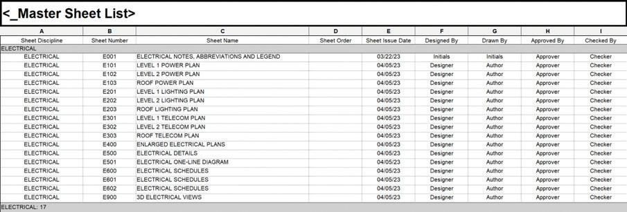
Similarly, to Placeholder Links, Placeholder Sheets can be created within your template/starter project. You can create these sheets in your Master Sheet List using “Insert Data Row” to add as many rows (sheets) as needed while you group and name them however you like knowing they may change from project to project. For MEPF, this is always the case because we match our sheet numbering and naming to what the Architect on any project is using. One Architect might use a A1.1 scheme, while another might use A101 scheme. I know there are several tools/add-ins out there that will let you create sheets very easily, but if you are creating the same sheets for every project, why create them each time when you can have them ready for you when the project begins.
The Selection Box command in Autodesk Revit is a useful tool for focusing on specific elements of your building model. When you select an element or a group of elements in your model and activate the Selection Box command, Revit automatically creates a 3D view that isolates and displays just those selected elements. This feature is particularly
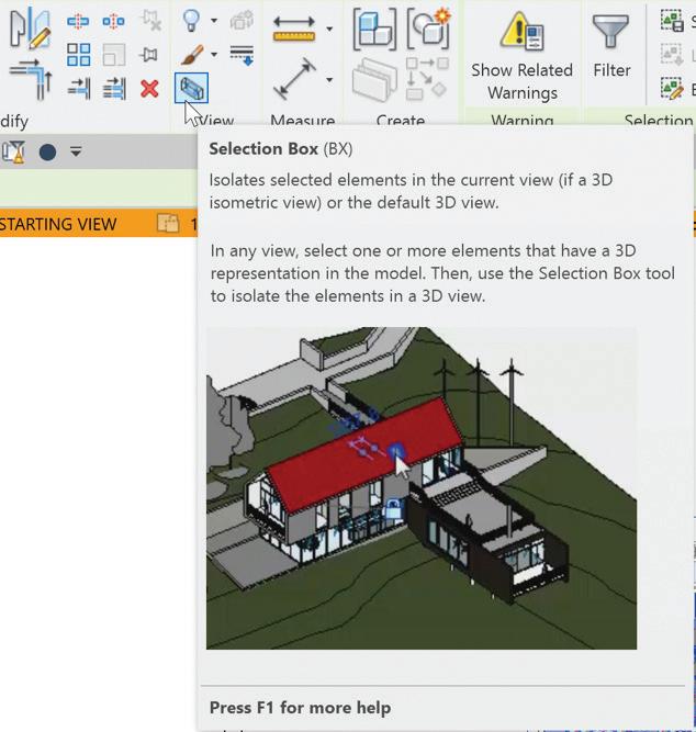
handy for closely examining a specific part of your project, such as a section of piping, a piece of furniture, or a structural component, by removing all other distractions from the view. It’s like zooming in on a small, detailed part of a large puzzle, making it easier to inspect, modify, or present just that area without the clutter of the surrounding environment. You can find this button on the Modify tab after your elements are selected. That 3D view can in turn be duplicated, renamed, and placed on a sheet for a more detailed view of that area.
View References are a painstaking process in Revit especially if plans are broken up into different sections and views have been created. These would then need to be placed and mapped to each section manually. I am here to let you know there is a simple way to get View References wherever you need them. To do this you would create dependent views for all the sections you need using whatever method works best for you for a single parent view. I recommend creating Scope Boxes for those
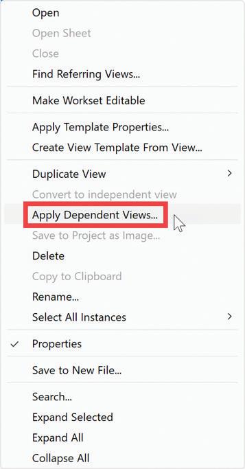
different sections as well. After your matchlines are placed, place your view references, and map them to each section. All you need to do now is to right click that parent view and select Apply Dependent Views. This brings up another dialogue where you can select all the views you wish to create the dependent views for.

After a small amount of time, depending on how many you are creating, all your dependent views have been created, all the view references have been placed and they are all mapped to the correct section. Now when those views are placed on a sheet, your view references will automatically update with that sheet information. This method saves you a ton of time and energy and minimizes frustration. The View Reference, like anything else in Revit, is also customizable to however you want it to look.

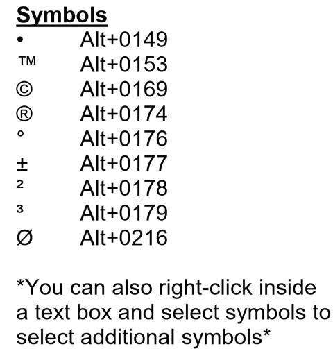
Engineering uses a lot of special characters, so I always include a short “cheat sheet” of commonly used special characters on our Projects Starting View. A user can also right click inside of the text window and select Symbols from the menu to access these and many other special characters.
Using Temporary View Properties is like having a set of temporary glasses that let you see your model in diverse ways. A user can quickly activate these properties with a few clicks, allowing them to focus on specific aspects of their design. They can experiment with different looks and settings, such as lighting or colors, to see what works best. This is incredibly useful for reviewing various parts of a large project or making sure everything fits together perfectly, all without the risk of messing up the original design or a view template that may be assigned to the view you are in. Changing the View Template instead of using Temporary View Properties can have adverse effects on the overall design and layout of your project so please be mindful of what you are changing and where you are making those changes. For example, a user can temporarily hide certain walls or floors to get a clearer view of the interior or highlight only the mechanical equipment without permanently changing the whole model.

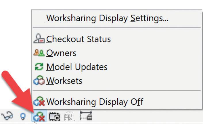
The Worksharing Display in Revit is a vital feature for teams collaborating on a project, enabling users to visually track and manage how different aspects of the model are shared and modified by team members. For instance, the BIM Manager or equivalent person in your office can easily see which parts of the building design are currently being worked on by any of the project team members, all through color-coded representations. This feature not only enhances coordination by clearly displaying ownership and work status of different model elements - like Electrical, Plumbing, or HVAC systems - but also aids in avoiding conflicts and overlaps in the project. With the Worksharing Display, users can also identify recently modified components, understand the distribution of work among team members, and efficiently manage updates and revisions, ensuring a smooth, collaborative workflow in complex, multidisciplinary building projects.
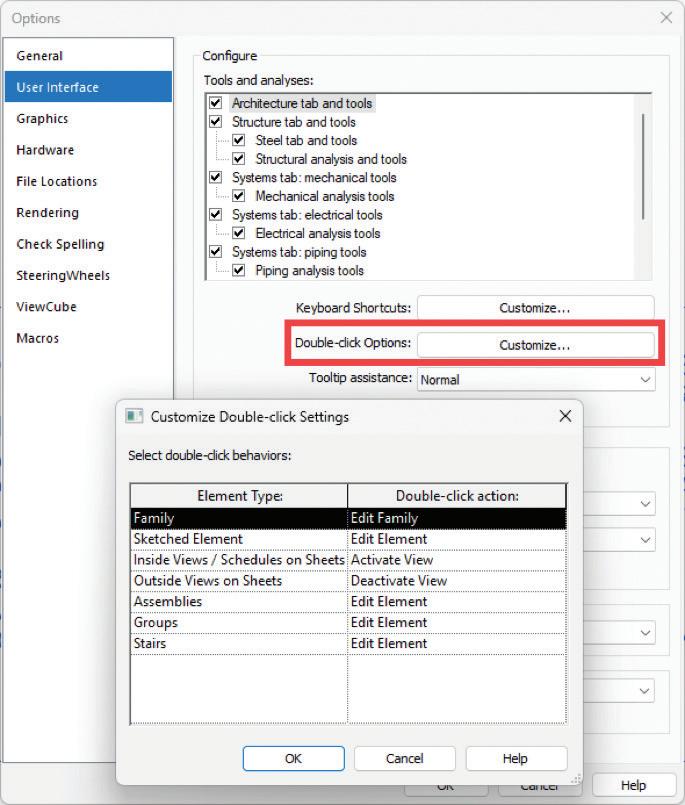
Customizing double-click options in Autodesk Revit allows you to streamline your workflow by setting specific actions that occur when you doubleclick on different elements within the software. This customization can enhance efficiency and make the interface more intuitive based on your personal or project needs. This customization is particularly useful for frequently performed tasks.
For example, setting a family to open in the family editor upon double-clicking can save time for users who regularly modify families. It is important to tailor these settings to your workflow to enhance productivity and reduce repetitive actions.
Here is a bonus trick or two I learned a long time ago. In the MEPF world, we all know that the Architect uses Floor, Wall or Ceiling Based families. Families built with those hosts are not usable for MEPF projects because we do not model floors, walls, or ceilings so what are we supposed to do if we need to use what the Architect is using? The short of it is, you can copy/monitor a select group of families from the Architectural model into the MEPF model and the hosting does not matter at that point because a copy of those families are in your model. However, what do you do if you want to use those families on other projects? First, I would create a simple project with some walls, a floor, and a ceiling. Download those families and load them into the project. Make sure they are assigned to the appropriate Revit category. Those categories are Air Terminals, Communication Devices, Data Devices, Electrical Equipment, Electrical Fixtures, Fire Alarm Devices, Lighting Devices, Lighting Fixtures, Mechanical Equipment, Nurse Call Devices,
Plumbing Fixtures, Security Devices, Sprinklers and Telephone Devices. Despite adding new categories in Revit 2022, those categories are not available within the copy/monitor function. In 2023 though, the new categories for Mechanical Control Devices and Plumbing Equipment can be copy/monitor from a linked model. Next you will need to place them where they should be, on the floor, the wall or on the ceiling. Save the file and close it. Create a new empty project and link the previous model into the new model. Open any 3D view and browse to the Collaborate tab to use the Copy/Monitor command. Select the link and copy those families into the new model. If you edit any of those families, they are now transformed into Face Based families. Save and rename as desired for future use. I would also recommend that you take the models you created and save them somewhere so that you can use them whenever you need to without having to recreate them.
How about I take the above trick to the next level. If you copy/monitor a wall-based family, not only will it be face based, but it will also change from being horizontal to being vertical. This is great way to convert wall-based Lighting Fixtures to face based families so that you can now utilize a nested generic annotation in the correct orientation without having to use Detail Items. In 2024 that has been fixed because Lighting Fixtures now have the maintain annotation orientation option built into them. If you are like me and the company I work for, the version we use for any given project is dependent on the Architect and what version they use. I currently have active projects in 2021 through 2024. All the content I build is currently in 2021 so every project uses the most up to date version of our families.
In conclusion, the world of architecture and MEPF engineering is evolving at an unprecedented pace, and Autodesk’s Revit stands as an invaluable ally in this ever-changing landscape. The Revit tips and tricks explored in this article are not just time-saving shortcuts or clever workarounds; they are keys to unlocking your full potential as a professional in these fields.
By incorporating these insights into your daily practice, you not only enhance your efficiency but also open doors to creativity and innovation. Revit becomes more than just software; it becomes a canvas on which your architectural and engineering visions come to life with greater precision and sophistication.
As you embark on your journey towards Revit mastery, remember that learning and exploration are ongoing processes. Keep experimenting, adapting, and refining your skills, and you’ll find that Revit becomes a powerful instrument through which you can shape a brighter, more innovative future for architecture and MEPF engineering. So, embrace these tips and tricks, and let your designs and projects soar to new heights.
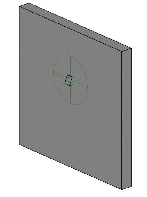
Ok one last trick, take that vertical family you just created, strip out all the modeled elements, add some reference plans constrained by dimensions/ parameters and save it as a family template. Now you can create all the vertical face-based families you want.

Jason Peckovitch is an Autodesk Revit Certified Professional for Mechanical and Electrical Design located in SE Iowa. He is a BIM Manager for Garver’s Buildings Business Line, specifically MEPF. Garver has nearly 50 offices across the United States and more than 1200 employees. His CAD/BIM career spans over 25 years but he didn’t switch to the AEC Industry until 2007 as a Mechanical HVAC Drafter and transitioned into BIM Management shortly after where he has been working since. Jason is also the father of three children; Shelby – 12, Blake –9 and Logan - 6, a published photographer, gamer, and car/tech guy. He can be reached at jmpeckovitch@ garverusa.com.




There are a lot of little things that go unnoticed in Civil 3D. Probably due to the fact that there are a million icons and commands! Whether they are hidden away within your Toolbox, or several layers deep within the ribbon, there are some really good tools that are often overlooked. Here are some of my favorite little tasks, some new, and some oldies but goodies!
Point cloud data feature extraction allows you to extract reference points and linear features, such as
a curbs and gutters as well as points, such as street signs, fire hydrants and light poles, from a point cloud dataset.
These tools are available in the Autodesk Construction Cloud viewer. Published ReCap point cloud projects have access to these extraction tools in the viewer.
From within the point cloud viewer, you will find the Feature Extraction command along the toolbar on the bottom of the screen. See Figure 1.

Once selected, you place your view direction in the direction you wish to extract your linear objects.
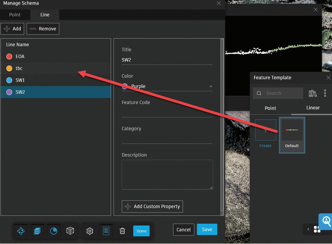
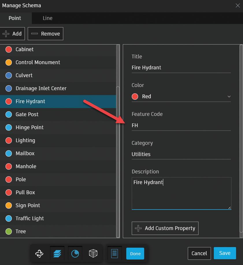
You can also set up pre-determined point types with feature codes for easy import into Civil 3D, as well as custom templates and naming convention for you extracted linear features. This will help speed up the import/processing of data in Civil 3D. See Figures 3 and 4.
Once you’ve adjusted your points on the section view, select Start Auto Extraction. You’ll visually see the features being created! See Figure 4.
If the extraction algorithm runs into an issue in the point cloud data that it is following, auto extraction will pause. A warning dialog will then display, offering two options:
• STOP. Extraction stops to allow the cross section to be adjusted. Extraction will need to be started again once complete.
• IGNORE. The extraction continues to the next cross section interval until the threshold is not met again.

Once stopped. You can edit the last cross section to adjust feature points or alter the direction path of the extraction.
Once you’re finished, select DONE at the bottom of your browser and the features will be added to a list in your project browser and can be exported out to a DXF or LandXML.
Need a quick volume analysis from a pond? Need that analysis every 0.5’ within the pond? The Stage Storage Tool in Civil 3D is your new best friend!
First, you need to decide what interval you need to report on. Your surface style will control the results/ interval within the report. For example, if I want the following pond volumes in 0.50’ intervals, I simply edit the surface style to display the correct interval, prior to running the analysis.
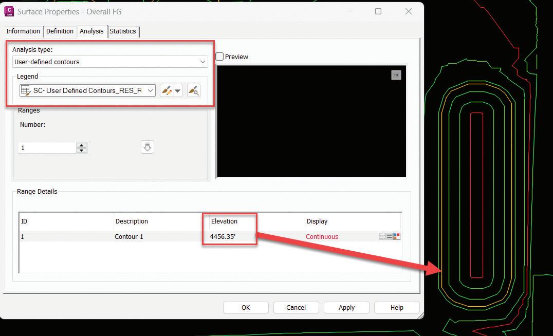
However, let’s take this one step further by using the User Defined Contour analysis from within your surface properties. Sometimes you may want to see the high-water mark, a pressure elevation or maybe a floodplain elevation. This is a great tool, and
coupled with the State Storage command can help you identify true volumes much easier. See Figure 5.
After you have edited your style to display the User Contour and your preferred contour interval, select the surface you wish to analyze, and from the Analyze panel of the ribbon, choose Stage Storage.
This will launch the report dialog box, fill in the blanks as needed, and select DEFINE BASIN.
You want to then select Define Basin from Polylines and select the Extract Objects from Surface button.
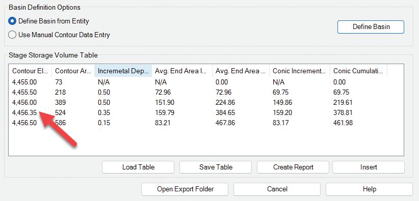
Select the surface, select DEFINE back on the dialog box and select up to the polyline you wish to analyze. The dialog box should reappear with your results and notice the oddball contour interval based on our user defined contour! You can save this report to a text file, or even better, save it as a file to be used within SSA!! See Figure 6.
An example for expressions is to use them to aid in labeling cut vs. fill labels in a volume surface. For example, you may want to display your CUT in red, and you FILL in blue. To do so, we will set up a couple quick expressions.
1. First, ensure you have a VOLUME surface created. This goes without explanation but thought I would mention it anyway!
2. Create two expressions, one for the Cut Text height and one for the Fill Text height.
3. Name this first expression Cut-Text. Use this as the expression:
• IF({Surface Elevation}<0,0.10/12,0.00000001)
4. Name this second expression Fill-Text. Use this as the expression:
• IF({Surface Elevation}<=0,0.12/12,0.00000001)
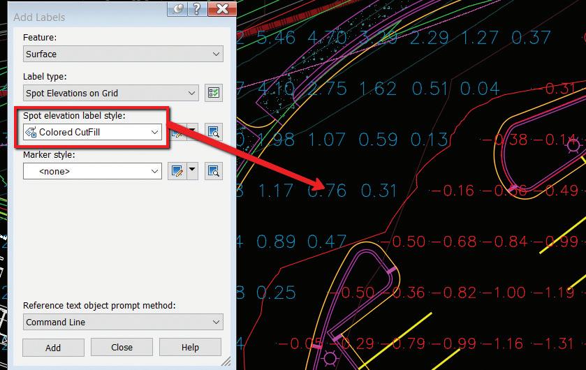
Figure 8
What we are doing here is creating a super small text that will NOT show up once we place our labels. These expressions are slightly different, we won’t use these in our label composer, but we will use these to adjust the text height and differentiate Cut v. Fill.
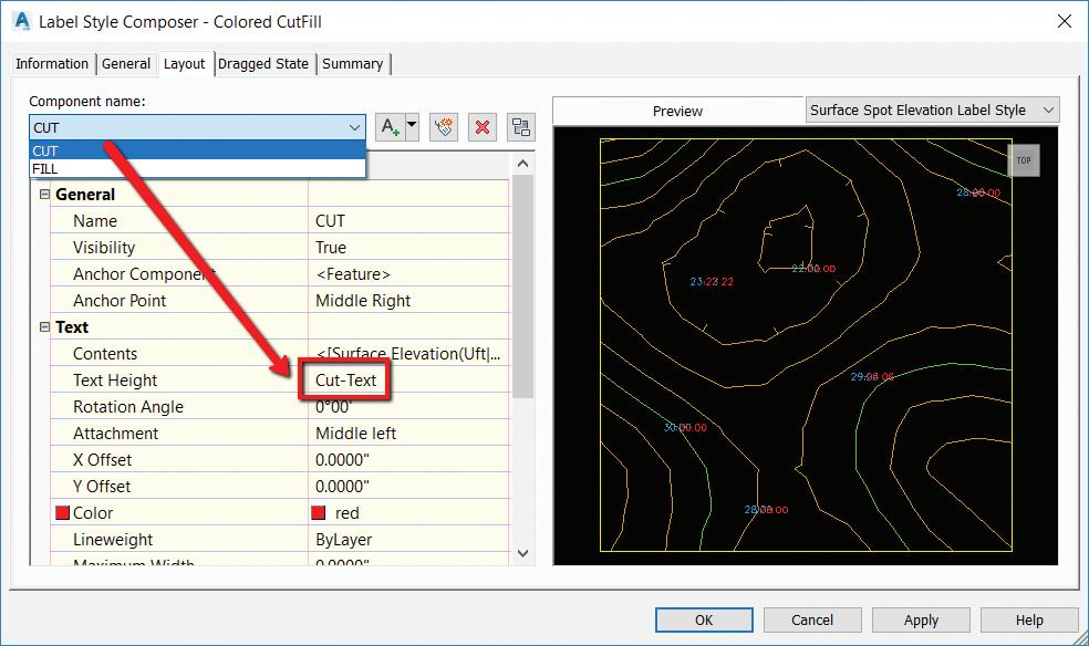
5. Create a label style that has 2 components, Cut and Fill text. These components reference the Surface Elevation, but in the text height property, you will set the corresponding expression (Cut/Fill).
6. Change the CUT component color to RED.
7. Change the FILL component to BLUE. See Figure 7.
8. Test this out by using your new label style to label a surface!! See Figure 8.
Here are a few other simple expressions I’ve used in Civil 3D.
Truncate your elevations. An example of this is displaying an elevation of 132.67 as 32.67:
• {Surface Elevation}-100*TRUNC({Surface Elevation}/100)
2 Point Slope Arrow – Arrow always pointing downhill
• IF({Surface Slope} <= 0, 0, pi)
• This expression gets applied to the Rotation Angle of the direction arrow component. See Figure 9.
Pipe True Slope
• ({Start Invert Elevation}-{End Invert Elevation})/ {2D Length - To Inside Edges}
Length in Meter – Display both (any object)
• {Segment Length} *.3084
Slope Distance AND Horizontal Distance in a label (Use on lines, polylines, figures and feature lines)
• SQRT({General Segment Length}^2(ABS({General Segment Start Z}-{General Segment End Z})^2))
Civil 3D now has added controls for transitioning subassembly parameter values across a defined station range. This allows for greater flexibility in modelling complex roadway features and saves

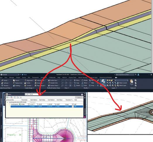
time setting up target linework, separate regions, and multiple assemblies.
You can also create linear, slope, and elevation transitions on corridor feature lines which reduces the need for complex, custom subassemblies.
Some of the top use cases include:
• Daylight slope transitions
• ADA ramps and driveways
• Bus bays
• Turn lanes
See Figure 10.
To create corridor transitions, first, select the corridor.
On the ribbon, on the Modify Corridor panel, select Edit Corridor Transition.
If the corridor has multiple baselines, you are prompted to select a baseline. Select the baseline in the corridor to which you want to add the transition. This may be an alignment or a feature line.
The Corridor Transition Panorama vista is displayed, and a prompt is displayed at the command line to select the subassembly to transition.
Hover over your corridor, on the subassembly you want to transition, and select it on the screen. After you select the subassembly, a list of available parameters in the subassembly that you can transition is displayed.
Select the parameter to transition from the list.
Select the start station of the transition.
Enter the parameter value at the start station. The default value is displayed in Panorama Vista.
Select the end station of the transition.
Enter the parameter value at the end station.
Specify the transition type.
If needed, continue to specify transition information by specifying the end station for the next transition. In this example, I’ve transitioned for a drive access by removing the curb and gutter back. Once completed, select Apply from the top right of the panorama. See Figures 11 and 12.


NOTE: You can copy and paste transition sets to the same corridor, a different corridor, or a corridor in another drawing. In the Corridor Transition Panorama vista, right-click a transition or a transition set to access the copy and paste commands.
There are always forgotten commands, or simple tips and tricks that may help us boost our productivity. I have been doing this for over 15 years now and I learn something every time I ask a question, or simply sit back and listen to others speak. Feel free to send me any of your favorite hidden commands or tips and tricks you have learned along your Autodesk journey.
Thank you!

Shawn has been a part of the design engineering community for over 15 years in all aspects of design, construction, and software implementations. He has implemented and trained companies across the Country on Civil 3D and other infrastructure tools and their best practice workflows. Shawn can be reached for comments or questions at sherring@ prosoftnet.com.
Greetings again, Gentle Readers! Now let’s go on with more information about pyRevit!
We’re going to explore more of pyRevit’s neat FREE tools that feature in pyRevit Extensions. But before that, as always, let’s get the formal introductions out of the way -
Gentle Reader - pyRevit.Extensions
pyRevit Extensions - Gentle Reader
Where may I find the fabled Extensions, you may ask? Let’s show you the way! Look for Extensions in the pyRevit tab.
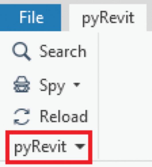


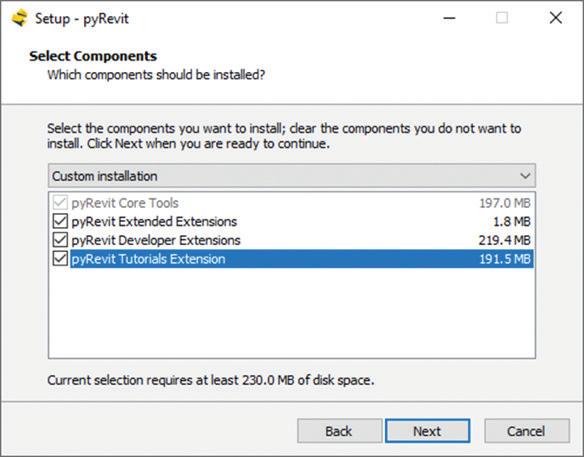
How do you make sure that you see the Extensions? While running the EXE file at the time of installation, please make sure that the option for Extensions is checked!
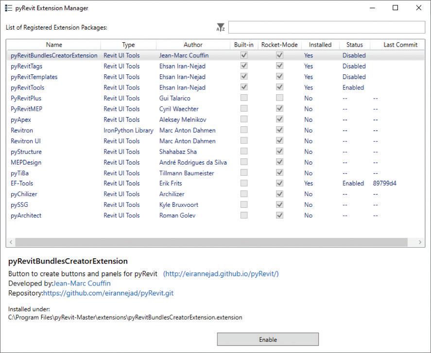
You will see a bunch of nifty tools created by a group of masterminds - Ehsan Iran-Nejad, Jean Marc Couffin, Erik Frits, to name a few. These tools are to supplement the available pyRevit and Revit tools. Some are Disabled by default - you can enable them as needed -

Some of them will need to be installed - if you don’t see an option to Disable / Enable them, they need to be installed. Click on the Extension to bring up the option to install it -

Note - These Extensions open in their own dedicated tab.
Now let’s look at some of my favorites!
EF_Tools -
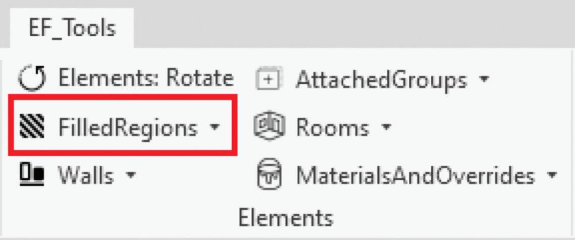
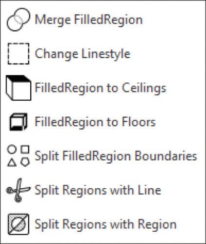
Let’s get to the point here - don’t like filled regions? Neither do I! Welcome to the club! Recently, my good friend Erik Frits mentioned some new additions that give more teeth to Revit filled regions (among the others you see in the screenshot!) in his contribution to pyRevit Extensions.

pyRevitPlus
Tools in the Tags group can help to keep your tags lined up and neat. The Smart Align tools can help you to keep multiple viewports on a sheet lined up and neat
pyChillizer
(It’s pronounced py-KILL-eye-zer, by the way….)
Top of the Pops in this Extension -

Dim Grids and Dim Levels - will place a single dimension string across multiple grids and levels.
Room Elevations - allow the creation of multiple elevations in the selected room.


Colorize View by Type
This tool allows you to apply desired colors to selected category (or categories) of model elements.


InPlace to Loadable - This is the one tool that makes it all worth it! A one button process to convert multiple InPlace models to loadable Families! Quicker and simpler than the previous workflows of converting groups into Families or cutting and pasting InPlace geometry into blank Families.
pyRevit Templates - This Extension shows up as a single button and not its own tab. This does wonderful things like generating a library of Filled Region swatches on a Drafting View and Filled Region types from FIll Patterns.


Finally - the pyRevit Bundles Creator - the place where all the magic begins.
Click here for more information about creating Extensions and Commands
A final word to the wise - as tempting as it may be to see your UI bedecked with all of these wonderful tabs, please restrain the urge, O Gentle Reader. You will be giving Revit much too much to do, spraining its teensy-weensy little brain, which can lead to undesirable aftereffects like poor performance, possibly model corruption. Unleash them with discretion ONLY on an as-needed basis. Disable / Remove the Extension once the need has passed. Better safe than sorry!
Watch out for the next episode, Gentle Reader! Until then - Keep Reviting!
Please let us know if you have some news to share with us for future issues. Likewise, if you are a featured product or news item user and would like to write a review, we want to know. Drop me a line at: rinasahay@gmail.com. We’d love to hear from you!

AUGIWORLD brings you the latest tips & tricks, tutorials, and other technical information to keep you on the leading edge of a bright future.