

AUGIWORLD
What's New?
The Official Publication of the AUGI Design Community June 2024 Diamond Sponsors Customizing with Subassembly Composer | Tagis: Revolutionizing Field Access to Critical Project Information
Also in this issue:

Get the ultimate performance for demanding applications on our most powerful compact tower featuring 14th Gen Intel® Core Processors, up to NVIDIA RTX ™ 4000 SFF Ada Generation GPU, 64 GB of memory and 9 TB of storage. Enjoy free technology consultations and exclusive savings for being a member of AUGI. Contact AUGI’s Account Executive Laura Ball at Laura_Ball@Dell.com or visit www.Dell.com/AUGI to learn more. WORKSTATIONS MADE WITH CREATIVES IN MIND Create your best work on the new Precision 3280 Compact Form Factor


augi.com/augiworld June 2024 | AUGIWORLD Magazine 3 CONTENTS 8 14 20 June 2024 AUGIWORLD FEATURES 8 BricsCAD What's New in V24.2? 14 3ds Max A Sneak Peek into 3ds Max 2025 20 Revit MEP What's New in Revit 2025 for MEP? 26 Civil 3D Customizing with Subassembly Composer COLUMNS 4 Letter from the Editor 6 Tech Manager 34 Inside Track
Letter from the Editor

As some of you may have noticed, we have switched month’s on the “What’s New?” issue. This gives the authors more time to receive and gather the actual new release of the product. It appears that most are not use to it yet, as we had some “What’s New?” in last month’s, and we have some in the month’s. We will get it eventually.
So, with the new releases, it seems there are some really nice features. A lot of us will argue with that statement, as most of us look for issues that have been resolved and fixed, opposed to new bells and whistles. Wouldn’t you agree? I thought so. Autodesk is still on the 2018 drawing version. This is a big change from the past. We are now looking at 2018-2025 on the same drawing format. As a Civil 3D user, this is great. However, we are not a odd year user. We upgrade every other year on the even versions. I think R13 broke a lot of people from upgrading to odd year releases. IYKYK!
On another note, AUGI just wrapped up a successful event, AUGICON 24. We had some outstanding speakers and content. If you missed it, the recordings will be available soon. You will not be able to view them unless you are a registered AUGI member. But, don’t forget, signing up to be a member is FREE!
We hope you enjoy this issue of AUGIWORLD. We are always looking for more authors and more content. If you would like to contribute, please email me at todd.rogers@augi.com.
Editor-in-Chief
AUGIWORLD
www.augi.com
Editors
Editor-in-Chief
Todd Rogers - todd.rogers@augi.com
Copy Editor
Isabella Andresen - isabella.andresen@augi.com
Layout Editor
Tim Varnau - tim.varnau@augi.com
Content Managers
3ds Max - Brian Chapman
AutoCAD
Civil 3D - Shawn Herring
BIM/CIM - Stephen Walz
BricsCAD - Craig Swearingen
Dassault Systèmes - Rafael Testai
Electrical - Mark Behrens
Manufacturing - Kristina Youngblut
Revit Architecture - Jonathan Massaro
Revit MEP - Jason Peckovitch
Tech Manager - Mark Kiker
Inside Track - Rina Sahay
Advertising / Reprint Sales
Kevin Merritt - salesmanager@augi.com
AUGI Executive Team
President
Eric DeLeon
Vice-President
Frank Mayfield
Treasurer
Todd Rogers
Secretary Kristina Youngblut
AUGI Board of Directors
Eric DeLeon
KaDe King
Chris Lindner
Frank Mayfield
Todd Rogers
Scott Wilcox
Kristina Youngblut
AUGI Advisory Board of Directors
Shaan Hurley Shelby Smith
Publication Information
AUGIWORLD magazine is a benefit of specific AUGI membership plans. Direct magazine subscriptions are not available. Please visit www.augi.com/account/register to join or upgrade your membership to receive AUGIWORLD magazine in print. To manage your AUGI membership and address, please visit www.augi. com/account. For all other magazine inquires please contact augiworld@augi.com
Published by:
AUGIWORLD is published by AUGI, Inc. AUGI makes no warranty for the use of its products and assumes no responsibility for any errors which may appear in this publication nor does it make a commitment to update the information contained herein.
AUGIWORLD is Copyright ©2024 AUGI. No information in this magazine may be reproduced without expressed written permission from AUGI.
All registered trademarks and trademarks included in this magazine are held by their respective companies. Every attempt was made to include all trademarks and registered trademarks where indicated by their companies.
AUGIWORLD (San Francisco, Calif.)
ISSN 2163-7547
AUGIWORLD Magazine | June 2024 augi.com 4


A Global Community for AEC Professionals to Learn, Grow and Exchange Knowledge. Become a member: www.dbei.org/membership
Fix –Finish

Last month we looked at the process of finding issues and addressing them as they escalate. We explained the process in brief as Find – Fix – Finish
There are four escalation points that you uncover during the investigations of the Find phase. Each conveyed below by the communication starters that might be:
• I am aware of…
• I am concerned about…
• We have an issue with…
• There is a failure...
You can go back and read about those, but having covered the Find portion, we move on to Fix and Finish.
THE QUICK FIX
During the Find phase, you probably gathered a good indication as to the scope and impact of the issue. You obviously need to get things back in working order, but if it is widespread and impactful, you need to get things going quick. This may entail a patch or a MacGyver style fix. MacGyver would fix things with whatever was around at the time. It was amazing what he could get done using paper clips, duct tape, or rubber bands. Not to be confused with
AUGIWORLD Magazine | June 2024 augi.com 6 by: Mark Kiker Tech Manager
MacGruber, who would mess things up even more. Sometimes your fixes need to be like MacGyver’s, using whatever you have to get through the pinch and get deliverables out the door or the system working again. You can come back later with the long-term fix, but for now, just get people working again.
THE WORK AROUND
It may be a workaround that uses other resources until the thing that failed is back online. You work around the log jam and divert the project flow in a way that returns progress but is not a long-term fix. It might be an export of data from one system and import into another that allows folks to keep going. It might be deploying older hardware that is not as fast, but at least it works.
THE SHORT-TERM FIX
Quick fixes and workarounds are not meant to stay in place very long, but sometimes the longterm fix will take a while to get up and running. You may have to order new hardware, reconfigure systems, reload/reinstall software or do something that will not get the main systems back up and working right away. That is when you need a bridging fix. One that can last long enough to give you time to get things back to normal. It might call for moving data, restoring a backup to another system, outsourcing some functions or calling in a contractor to get things running.
THE LONG-TERM FIX
This is the goal. To get things back to where they were as if it never happened. If the short-term fix is in place and you have some time, think through what is needed and make continuous progress on the long-term. Getting things back to what they used to be is good, but there might even be something better…
THE IMPROVEMENT FIX
There are times when the long-term fix can also include an improvement. I always look for these. I know that I need to get things back to working for the long haul, but if there is a possibility of wedging in an improvement in that fix, then I try to do it. Replacing old hardware, installing an upgrade, or making a change that you knew needed to happen helps everyone. I always have a short list in my head or on paper of things that I would like to do if I had time. It might be something that you want to do but did not want to interrupt the workflow. Well,
now may be the time to do that. The workflow has been interrupted and if an improvement can be slotted into a fix, make it happen.
THE POST FIX ASK
If things have settled after the disruption, it may be a good time to seek funding. Now is the time to ask for something that you have postponed or have had denied before. If you had put this in place, the break would not have happened. Maybe it was a postponed hardware upgrade, or you have gone too long with some old piece of software. These troubles are not going to get better; we need to make some improvements. Now is the time to ask. Make sure that any frustrations with the break have been alleviated, then make the ask.
THE FINISH
Prepping for a post fix ask is done by finishing well. When the fix is in place, you need to let everyone know that things are back on track. Let them know what the issue was and how it was fixed. Circle back in a day or two and ask if things are still fine. The finishing touch can perp people for your request if they are thinking about avoiding the next breakdown.
The Find, Fix, Finish cycle comes around again and again. By staying on your toes, you can avoid some of the breakdowns. When they do happen, you can get folks back to being productive quickly.

Mark Kiker has more than 35 years of hands-on experience with technology. He is fully versed in every area of management from deployment planning, installation, and configuration to training and strategic planning. He is an internationally known speaker, writer and former AUGI Board member and president. Mark is currently serving as Chief Technology Officer for SIATech, a non-profit public charter high school focused on dropout recovery. He oversees two web sites, www.caddmanager.com and www.bimmanager.com. He can be reached at mark.kiker@ augi.com and would love to hear your questions, comments and perspectives.
augi.com/augiworld June 2024 | AUGIWORLD Magazine 7 Tech Manager
by: Craig

BricsCADWhat’s New in V24.2?
BricsCAD® V24.2 is here, bringing with it a suite of performance improvements that promise to boost efficiency and stability with new and enhanced features for 2D drafting, 3D modeling, civil, survey, BIM, and mechanical workflows. Tailored for drafters, designers, and fabricators across all industries, the latest version focuses on accelerating the creation of detailed design documentation essential for building, fabricating, and manufacturing processes. With this release, the Bricsys development team included several new features and improvements to help you accelerate your time to deliverable and provide you with a familiar CAD experience. With the help of the global technical teams at Bricsys®, let’s dive in and explore what’s new in BricsCAD V24.2!
2D DRAFTING ENHANCEMENTS
With V24.2, we’ve worked to make your drafting and design processes easier. To help your drafting run smoothly, we made improvements to:
Sheet Set Manager: We’ve improved the Sheet Set Manager so you can preview DST files faster, add new sheets quicker, save model views, and delete viewports that will automatically be removed from the list.
Custom Paper Size Management: It’s also now possible to manage custom paper sizes with full support for PMP files.
Nested Purge Access: The PURGE command was enhanced to allow dialog access to the Nested
AUGIWORLD Magazine | June 2024 augi.com 8
Swearingen BricsCAD
Purge functionality so you can run it from the Purge command or via the Drawing Health Manager.
Hide Objects: BricsCAD’s status bar now indicates hidden objects, so you know that items are either hidden or isolated in the drawing, and it’s easier and quicker to discover what those are. You can turn this off and on as needed.
ENHANCED DRAWING COMPATIBILITY
One of the key improvements to BricsCAD V24.2 is its enhanced DWG and drawing compatibility. Our focus was on the highest DWG compatibility to ensure that the drawings you create can be opened and edited in other DWG-based CAD tools so you can collaborate effortlessly. You’ll find:
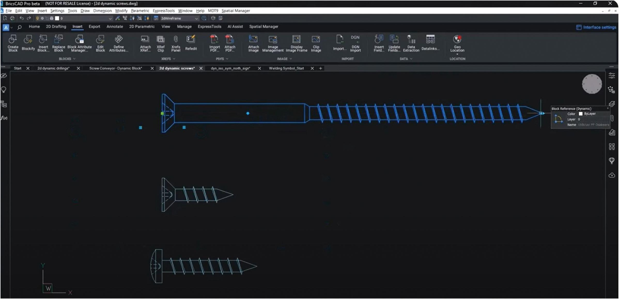
Improved Dynamic Blocks: We focused on improving how BricsCAD handles AutoCAD® Dynamic Blocks. Dynamic blocks perform true to form when using the grips to stretch a block, and the same is true when flipping. Stretch accents behave as expected, as well as rotation and mirroring grips. (See Fig. 1)
Complex dynamic blocks like welding symbols are also now more accessible to work with. You can select and change attributes on the screen using the properties panel or drag the blocks. You can also flip welding flags and mirror blocks using the improved grips.
Improved Rotation Parameters: Dynamic Block’s rotation attributes remain correctly preserved whilst direction attributes are rotated accordingly.
Improved MLeaders: Mleaders have been improved to behave as expected in BricsCAD and on a round-trip to other CAD software. We upped DWG fidelity by improving how Mleaders behave. When you change an MLeader in BricsCAD, the existing MLeaders will update, and their attributes are preserved. Similarly, if you redefine a block used in an MLeader, the MLeader will have the updated attributes.
ENHANCED 2D DRAWING CREATION WORKFLOW
Understanding the critical nature of 2D drawing creation in the design process, the BricsCAD team dedicated their efforts to refining this aspect in V24.2. The enhancements are designed to reduce the time to deliverable, making the software not only faster but also more reliable. This ensures that users spend more time designing and less time waiting on the software or worrying about potential data loss.
Improved DWG Load Performance: One of the standout features in V24.2 is the enhanced DWG loading capability. For those working with large drawings, the frustration of waiting for all items to load is all too familiar. BricsCAD V24.2 addresses this
augi.com/augiworld June 2024 | AUGIWORLD Magazine 9
BricsCAD
Figure 1
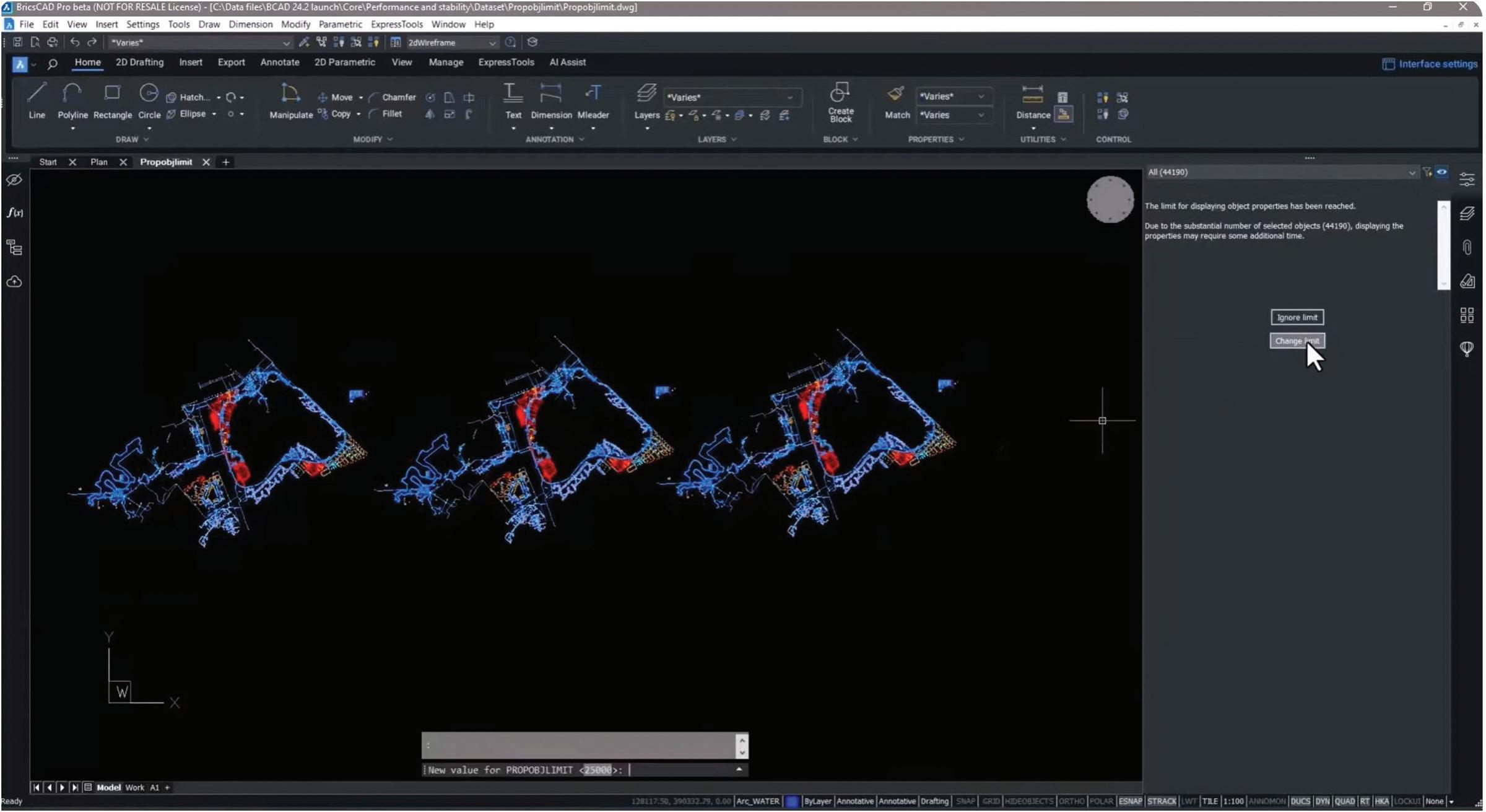
by implementing Prop Object Limits, significantly speeding up the process. With Prop Object limits, you can set a limit value so when you “Select all”, the properties panel lets you know when the limit is reached. Prop Object Limits eliminates the enumeration of selected objects shown in the Properties panel, cutting down on loading time. You can always override the limit or change it. (See Fig. 2)
Enhanced External Reference Workflow: Managing attachments aka external references (XRefs) is now more straightforward. Now, you can detach an Xref with zero references without needing to unload it first, saving you precious time and clicks!
Optimized Display Performance: Users will notice a marked improvement in the display performance of spline-fit polylines and color-mapped point clouds. These enhancements reduce memory usage, leading to a smoother user experience.
UPDATED PURGE DIALOG
We updated the PURGE dialogue to allow dialogue access to nested purge functionality either from the standalone command or from the drawing health manager.
BRX API ENHANCEMENTS
In addition to the core performance improvements, BricsCAD V24.2 introduces enhancements to the BricsCAD BRX API, opening up new possibilities for our Developer Partners to create more efficient and powerful applications for BricsCAD, further expanding its capabilities.
With this release, we worked to ensure product stability, performance, and optimal 2D drawing creation workflows in BricsCAD V24.2 so our users can reach their design deliverables faster and more efficiently than ever before.
CIVIL TOOLS IN BRICSCAD V24.2
Quicker display of color-mapped point clouds: Color-mapped point clouds are now much quicker to display. Users will also notice a marked improvement in the display performance of splinefit polylines and color-mapped point clouds. These enhancements reduce memory usage, leading to a smoother user experience. You can change color schemes faster and save on memory use - saving you time! (See Fig. 3)
Enhanced GIS Import: We enhanced the GIS import command to allow you to import data from a file-based geodatabase. We also enhanced the
AUGIWORLD Magazine | June 2024 augi.com 10 BricsCAD
Figure 2

user interface and added new dialog boxes to work with point groups and editing TIN surfaces, making these commands easier to learn and faster to use.
Streamlined shape file import: In BricsCAD Pro V24, we have streamlined the import process for shape files. You can select a folder directly and have the software tell you which files you have already loaded. You can import all your data or define a Clipped Polygon within your drawing to display only what you need.
Edit field names and formats: New to V24.2 is the capability to edit field formats and names, so you can ensure that anyone receiving your data can understand each field attribute.
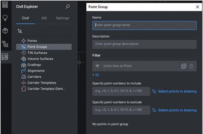
New user-friendly dialogs for point group management: This release includes user-friendly dialogue boxes for point group management. Rather than working solely with the command line, the new dialog lets you create new point groups, add descriptions, and select points you want to include within the group. The dialogue indicates how many points you have chosen. You can also add to or create new point groups using the filter box, which makes it easier and more intuitive.
(See Fig. 4)
New TIN surface dialogs: We created new dialogues for working with TIN services, including removing elevations, removing the outer edge, adding brake lines, and removing points per elevation within a TIN surface.
BRICSCAD BIM V24.2
BricsCAD BIM is a flexible and accurate BIM tool for CAD. With the release of BricsCAD BIM V24.2, we wanted to make it easy to go from 2D or scan data to 3D BIM, make it easier to handle IFC, increase the efficiency of scan data, and make this data more insightful.
New BEAM tool: We added a new BEAM tool to the building modeling toolset to make it easier to design your buildings. A dedicated panel displays parameters and lets you choose from a single or polybeam or a shape from your library. You can also specify your materials and set key parameters to place beams with the correct dimensions, spatial location, and other BIM elements. These are available for use with the Bill of Materials.
Enhanced Wall Tool: We enhanced the wall tool based on customer feedback. Now, BricsCAD recognizes walls even if they’re at an angle to the X&Y. It also recognizes wall thickness automatically
augi.com/augiworld June 2024 | AUGIWORLD Magazine 11 BricsCAD
Figure 3
from the point cloud, making it easier to go from scan to 3D model to BIM model.
Enhanced Roof Tool: We added additional functionality to the roof tool in BricsCAD BIM V24 to make it even more useful, and you can now create a roof with polylines using polyline mode. You can adjust thickness, overhand, and angles on the fly and fit roof endings.
New IFC Setting Dialog: We introduced a new IFC dialogue setting dialogue box to make IFC data less confusing and easier to handle. You can also filter which entity types are for import. Choose from predefined profiles for quick and straightforward importing or specific elements like structural or MEP elements.
Point Cloud Color Mapping Classified Data: We established a new data representation that allows you to color map classified data - helping you gain insights and work with point cloud data more quickly. You can also change colors for better visualization.
Updated AMPARTREF: In BricsCAD V 24.2, we’ve updated our AMPARTREF feature. You can now reference existing part references, so you no longer need to recreate them manually. These new part references are associative with the existing parts list.
New BricsCAD, Block Reference: Now, you can reference an existing BricsCAD block. The metadata in the block automatically transfers to the part reference.
AMBALLOONS made simpler: Creating AM balloons is more straightforward in BricsCAD Mechanical V24 with the AMBALLOON command. It creates balloon annotations fully compatible with the AM BOM database on existing DWG files and blocks created in BricsCAD. You can easily arrange several balloons simultaneously with predefined vertical and horizontal placement or choose custom angle placements.
AUGIWORLD Magazine | June 2024 augi.com 12 BricsCAD
BRICSCAD MECHANICAL V24.2
Figure 4

Improved AMPARTLIST
workflow: We improved our AMPARTLIST workflow by adding a dialog box to enable more configuration. Here, you can easily edit part property values. You can now set incremental or fixed values to a range of cells, ensuring accurate item numbering. Layout configuration settings give you complete control of how your parts display. Once you save the changes, you’ll see they are automatically reflected in the parts list. (See Fig. 5)
CONCLUSION
Whether you’re a seasoned CAD professional or just getting started, the new and enhanced features in BricsCAD V24.2 are sure to enhance your workflow and accelerate your time to deliverable! Head to the official Bricsys Youtube page and watch Don Strimbu and Lynda Sharkey demonstrate a majority of this in action. And just wait until you see what Bricsys has in store for BricsCAD V25!
MORE ABOUT BRICSCAD
Bricsys BricsCAD is professional CAD software without compromise. Accelerate your time to deliverable without compromising on performance, cost, licensing flexibility, and data security. Not ready to buy? Download the free, 30-day trial of BricsCAD at Bricsys.com. Would you like free lessons? We have that available with Bricsys Learning. Ready to migrate to BricsCAD? Download the Migration Guide. The latest version of BricsCAD improves the tools and features users love, as well as new functionality and UI that supercharge productivity. Follow us today on LinkedIn and Youtube.
MORE ABOUT BRICSYS
Bricsys, part of Hexagon®, is the global technology company that creates the BricsCAD family of computer-aided design (CAD) products and the Bricsys 24/7 project collaboration platform. We are relentlessly committed to the success of our customers by offering cost-effective, missioncritical CAD software with industry-leading product support. Learn more at www.Bricsys.com. Hexagon is a global leader in digital reality solutions. Learn more about Hexagon (Nasdaq Stockholm: HEXA B) at hexagon.com and follow us @HexagonAB.

Mr. Craig Swearingen is a Global Implementation Specialist and Consultant at Bricsys. Currently, Craig provides migration and implementation guidance, management strategies, and technical assistance to companies which need an alternative, compatible CAD solution. Craig spent 19 years in the civil engineering world as a technician, Civil 3D & CAD power user, becoming a support-intensive CAD/ IT manager in high-volume production environments. Craig is a longtime AUGI member (2009), a Certified Autodesk® AutoCAD® Professional, and he enjoys networking with other CAD users on social media.
augi.com/augiworld June 2024 | AUGIWORLD Magazine 13
BricsCAD
Figure 5
A Sneak Peek into 3ds Max 2025

ds Max professionals will be grateful that Autodesk focused on updating several features and improving 3ds Max’s overall user experience. We’ll review some of those updates in this month’s article:
• A search feature that is globalized, producing more context-related options. The search maintains a history of the last several actions, making them easy to locate and repeat and friendly options to manage the interface (Figure 1).
• A drag-and-drop menu editor also provides a streamlined method to manage menus and quads, allowing users to customize their space for their favorite production easily. Its plug-andplay style updates are equipped with separators,
renaming, and more, making it easier to customize the space and allow developers to build content using its underlying foundation (Figure 2).
• Anyone who works in 3D understands the foundational importance of incremental saving. There’s now a direct Incremental save option located under the file menu.
• 3ds Max’s retopology, introduced only a few years ago, was incredibly powerful and continues to grow. Now, it includes options such as preprocessing to allow for more iterative control and updates to OpenVBD, making it even more user-friendly than before and one of the most potent retopology tools in the 3d space.
AUGIWORLD Magazine | June 2024 augi.com 14 by: Brian Chapman 3ds Max
3


augi.com/augiworld June 2024 | AUGIWORLD Magazine 15 3ds Max
Figure 1 – Improved Search Feature
Figure 2 – Improved Menu Editor
• 3ds Max has always been a powerful option for building mesh geometry natively without some of the most common errors; however, they added options in the Mesh Cleaner modifier, such as Zero Area UVs, Isolated Vertices, and more. While 3ds Max has generally been built to construct clean meshes natively, these are essential to working with game engines and controlling final render quality—ensuring there are fewer anomalies.
• Material makers will appreciate the update to the slate material manager, allowing them to view bitmaps simply by right-clicking the node rather than digging through the panels.
• OpenColorIO is now the default color system for 3ds Max, using the ACEScg color space. That should help streamline the working process between real-world cameras and the final render while allowing artists to work with various applications and production methods using various color management tools and systems. As many programs in 3D have implemented the ACES color space, this should help with quality between products.
• For gaming and other applications, vertex painting and output tools are now empowered with color management and color space options, giving users finer control over exports.
• Autodesk continues to lean into USD, providing more updates to 3ds Max for animated cameras, blend shapes, improved instancing (of lights, for
example), and more. USD provides an excellent tool for several people to work together on individual scenes, allowing companies to expand their workforce to use various production methods.
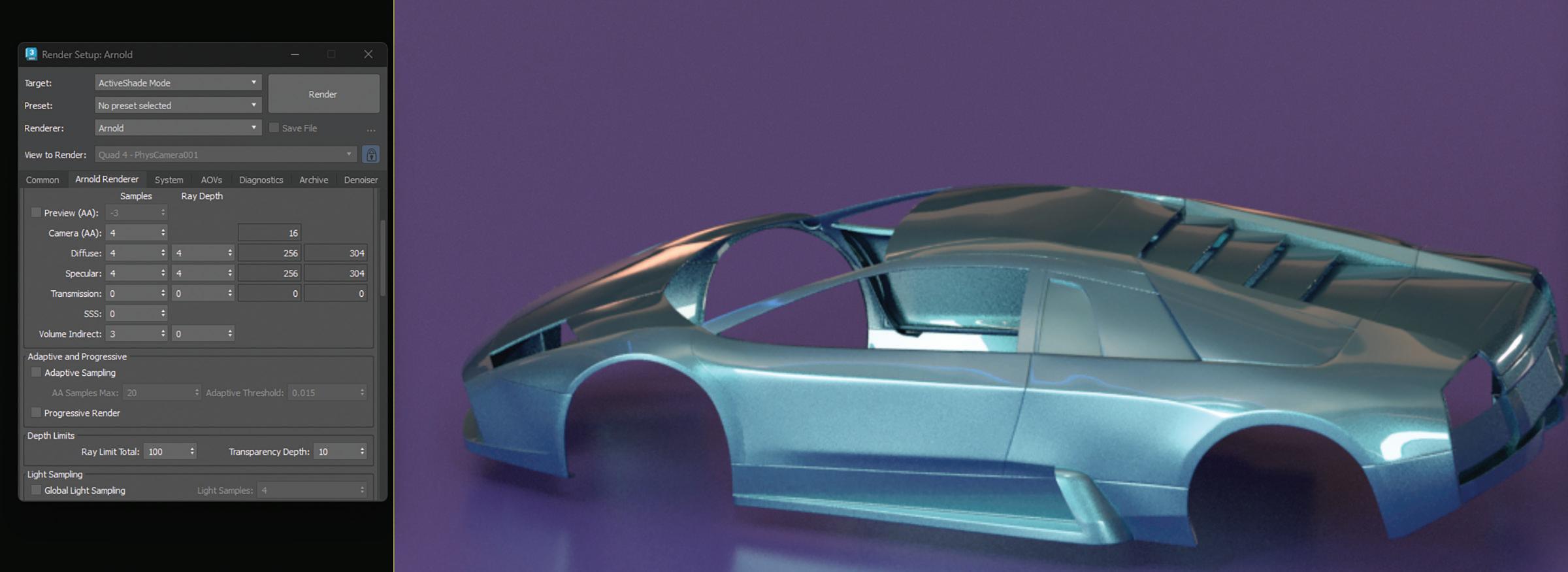
• Finally, Arnold’s renderer received improvements to make rendering noticeably faster, providing options like global light sampling in volumes, improved distance shader reflections, an overlay imager to decorate or tag images easily, improved renders of thickened curves, exports of more AOVs, and much more (Figure 3).

Brian Chapman is a Las Vegas 2D/3D design professional who creates content for the AEC industry, games, film, entertainment, and software development. Brian can be reached at procadman@procad.net.
AUGIWORLD Magazine | June 2024 augi.com 16 3ds Max
Figure 3 – Arnold Render Improvements
Bright Ideas for a Bright Future

AUGIWORLD brings you the latest tips & tricks, tutorials, and other technical information to keep you on the leading edge of a bright future.

What’s New in Revit 2025 for MEP?
Revit MEP by: Jason Peckovitch
Discover how the latest version of Revit
can help you design, model, and document
MEP
systems with more efficiency and accuracy.
There are nearly 50 enhancements and features in the Revit 2025 release. Compared to other years, it’s on par. The initial release of 2024 had 44 and there were 64 in the initial 2023 release according to the Autodesk Help website. These numbers do not include any features or enhancements from the “point” releases of 2023 or 2024. I highly suggest visiting Autodesk Help to get the full list of features and enhancements.
Some, maybe most, may not agree with me, but I believe this release is quite lackluster. There really has not been any significant amount of MEP improvements in quite some time. Sure 2022 and 2023 added some much needed new (mostly MEP) categories but only the 2 from the 2023 release got ribbon buttons. Here we are in the 2025 release and those new categories from 2022 still do not have a ribbon button nor can we create a keyboard shortcut for them. Why is that, Autodesk?
NEW MEP FEATURES
The Autodesk Help website has a Highlights or Core Features section to show you the new features they want you to focus on. These features have a lot of information, screenshots, links and sometimes videos. The link to these features also has an image of the feature. The next section is More Features. These features have less information still some still have an image of the feature. Some of the More Features, however, do not have an image of the feature and they usually have less information than the other features. Autodesk must feel these features are not worth the time to embellish them like the others. Aren’t all the features noteworthy and shouldn’t they get an ample information page? But alas, here is where you will find the 4 MEP specific features in this release, the bottom of the barrel so to speak. Those features are:
Single Phase Electrical Components
The use of Single-Phase electrical components is now supported by Electrical Loads and Distribution
Systems which includes using them in both analytical and physical models.
Disable Mark Auto-generation
Autodesk has disabled the auto-generation of the following MEP categories: MEP Ancillary Framing, MEP Fabrication Stiffeners, Air Terminals, Mechanical Equipment, Duct Accessories, Electrical Equipment, Electrical Fixtures, Mechanical Control Devices, Lighting Fixtures, Pipe Accessories, Sprinklers, Plumbing Fixtures and Plumbing Equipment. For example, in Revit, once you’ve identified your VAV box as VAV-1, it won’t automatically assign the next value to the Mark parameter for any subsequent VAVs you place. Previously this automatic incrementation would stop when you stop using that specific family or start a different Revit command. That no longer happens in this version of Revit. Maybe this is yet another good reason to not use the Mark and Type Mark parameters. They still throw warnings when that information is duplicated.
MEP Parameters
This is supposedly a feature from the community ideas forum, but only 2 new parameters have been added to data panels and fabrication ductwork. The Maximum Amount of Circuits parameter that is available on Electrical Panels has been added to a Data Panel (Part Type = Other Panels). Does anyone use a Data Panel? I’ve personally never created a Data Panel schedule/template.
Material Gauge has been added to Fabrication
Ductwork as a read only parameter. Gauge has been made available as read only for design ductwork as well in a previous release so 2025 extends that enhancement to fabrication ductwork.
Report Low Voltage Panels
The connected power circuits will now show the power loads from low voltage panels. The power distribution system reports their power usage when you look at them in the System Browser or panel
augi.com/augiworld June 2024 | AUGIWORLD Magazine 19 Revit MEP
Revit MEP
schedules. This information helps you to balance loads effectively across your electrical systems.
New and Updated General Features
Besides the MEP-specific features, Revit 2025 also includes new and updated general features that can benefit all Revit users, regardless of their discipline or industry. While I will not be showcasing all of them, I will highlight some that could be beneficial. One of the most notable general features is the new Sheet Collections. Autodesk must think so as well because it is the 5th highlighted new feature.
Sheet Collections

With the new Sheet Collections feature, you can create custom groups of sheets where sheets can now have the same sheet number if those sheets are in different sheet collections. You can easily drag and drop sheets into different collections or change the new Sheet Collection parameter. To create the new Sheet Collection, just right click on Sheets in the Project Browser and select New Sheet Collection.
Surprisingly you will have to right click or double click to rename the Collection. Not sure why it does not give you the option to name it as you created it. *shrugs* (Figure 1).
Background Export to PDF
Using the Export PDF button in Revit now gives you the option to export those PDFs in the background

AUGIWORLD Magazine | June 2024 augi.com 20
Figure 1 - New Sheet Collection
Figure 2 - Export in background
which allows you to continue working while waiting for the PDF to be created (Figure 2).
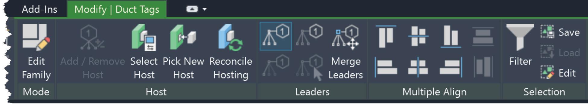
Multiple Alignment
With multiple text notes, tags and keynotes selected, there are new options in the modify ribbon that allow you to align the selected annotations in various ways, vertically and horizontally. Additionally, you can evenly space those annotations between the first and last one selected. I can see this being very handy when cleaning up details (Figure 3).
Next Generation Insight
Autodesk Insight is a platform that helps you explore and understand critical designperformance decisions, using flexible data and analysis. To use this service, you need to install the Carbon Insights Add-On in Revit from your Autodesk account. This tool is easy to use and can
improve your knowledge of your design’s impacts (Figure 4).
gbXML Update
Revit 2025 has been updated to use gbXML v7.03 to use with your 3rd party HVAC loads program(s). The latest schema includes support for:
• Extended HVAC system data
• Zone Equipment
• Air Systems
• Water Loops
Horizontal Coordinates
Revit 2025 has added support for five horizontal coordinate systems to enhance collaboration workflows. DWG files that utilize any of the five new horizontal coordinate systems listed below can be linked, allowing you to acquire the coordinates from the DWG.

augi.com/augiworld June 2024 | AUGIWORLD Magazine 21 Revit MEP
Figure 3 - Multiple Alignment
Figure 4 - New Autodesk Insights
Those newly supported horizontal coordinate systems are as follows:
• CGCS2000
• UK GG951
• Amtrak Northeast Corridor
• US Albers NAD83
• ISN2016
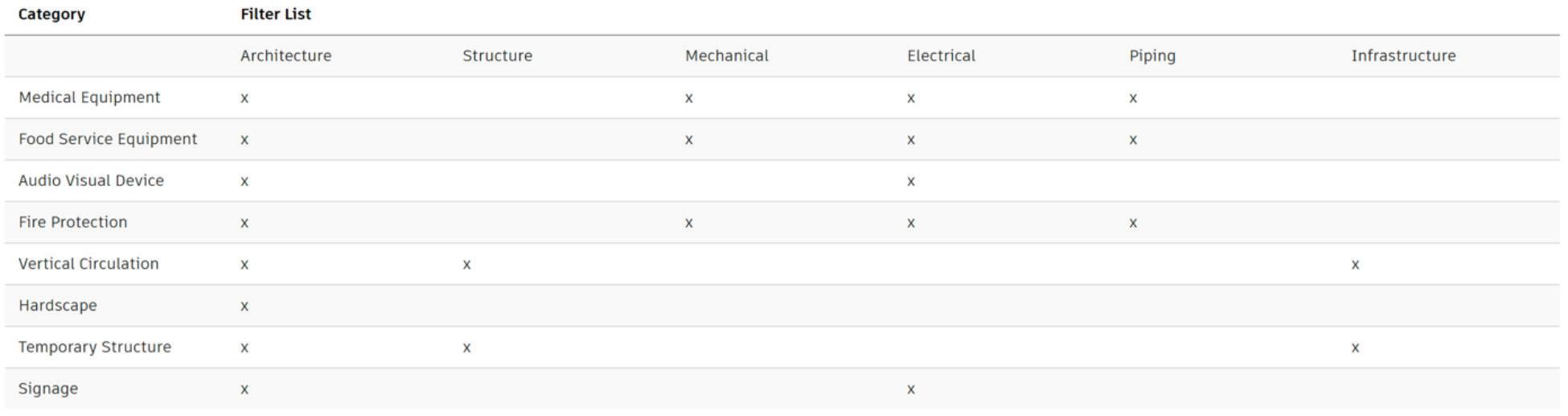
Filter Discipline Updates
The new categories that were created in the 2022 release of Revit no longer show up in the Visibility/ Graphics Override for Model Elements when filtering for specific categories within a specifically checked discipline (Figure 5).
Extensible Storage Improvements
Schemas are data structures created by add-ins to store data in a model or family’s extensible storage. Each schema must have a unique ID to avoid conflicts. Schema conflicts typically arise when a vendor recycles the software code and ID in an add-in. Revit cannot operate with duplicate schemas present. To resolve this, data from one of the schemas must be removed. Using an add-in that relies on this data may lead to unpredictable behavior or cause the add-in to malfunction. Schema Conflicts have plagued the pre 2024.2 release of Revit. I know all too well about this as I had a 2024 project have all the previously loaded content deleted from the model when someone opened the model and hit continue when the Schema Conflicts popped up, yes multiple of them in a single model (Figure 6).

In 2025, you can deal with schema conflicts better when they happen. These changes also reorganize how extensible storage is used to reduce risks and improve workflows.
.NET 8 Upgrade
Revit now uses Microsoft’s .NET 8 framework, which helps with UI dialogs, Windows interactions, the Revit API, and more. Revit moved to .NET 8 to keep up with the technology and maintenance. This is a welcome update for developers which allows them to utilize the increased
AUGIWORLD Magazine | June 2024 augi.com 22 Revit MEP
Figure 5 - Category Filter Updates (via Autodesk help)
Figure 6 - Schema Conflicts
functionality with .NET 8 since Revit was previously using .NET 4.8.
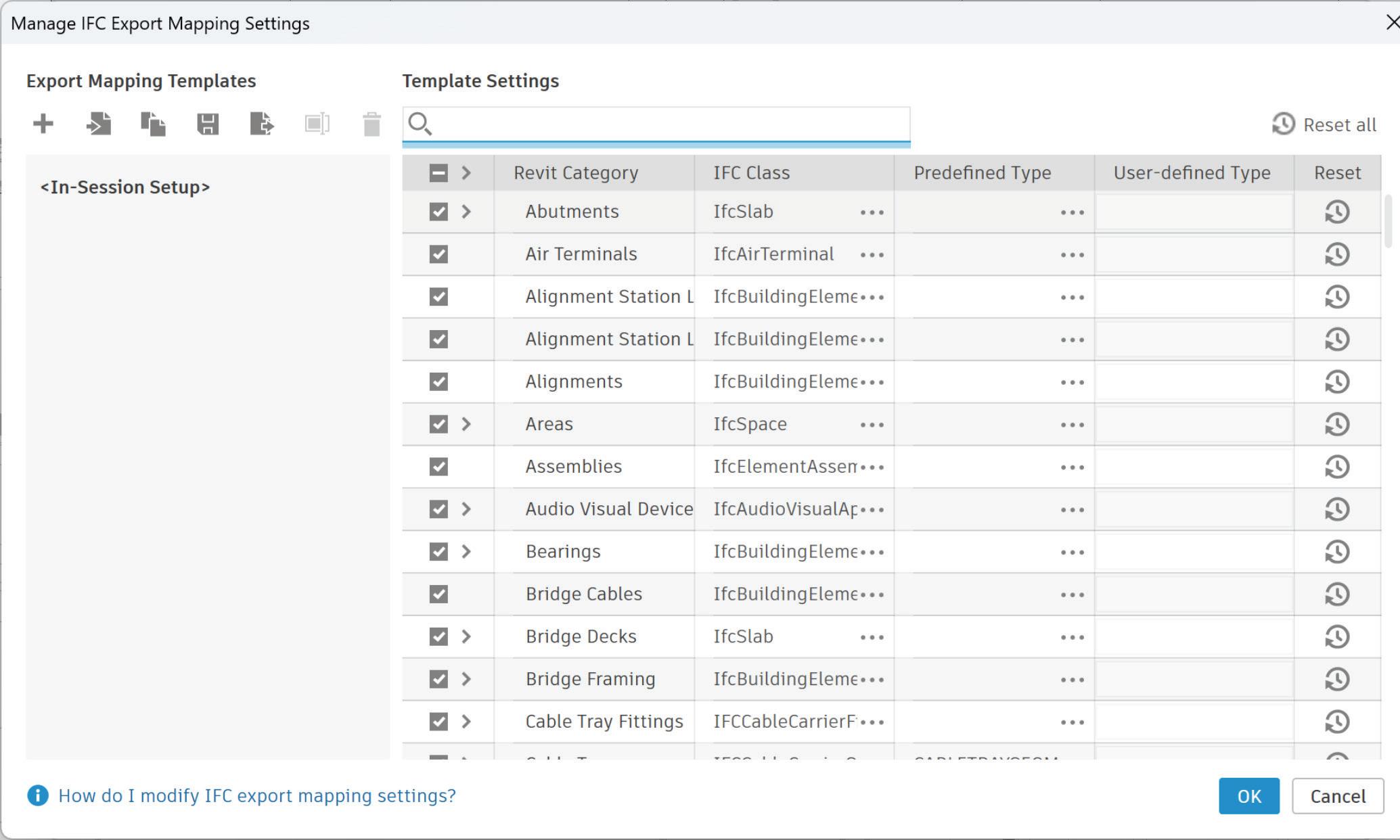
IFC Export Category Mapping Templates
For those working with IFC, users can now use templates to customize Revit category mapping for IFC exports. These templates can also be exported and used in other Revit models (Figure 7).
IMPROVED MEP FABRICATION MODELING
There are more Fabrication improvements in this release of Revit than what was released for MEP. They have been a staple of the new Revit releases for quite some time now. I personally do not know anyone who is using Revit to convert their or someone else’s design model to a fabrication model nor have I used them professionally. I am sure someone is using it, why else would Autodesk continuously add new Fabrication improvements.
I won’t go into detail about them but here is a list of what those improvements are:
• Edit Part Geometry
• Analytical Duct and Pipe Segments

augi.com/augiworld June 2024 | AUGIWORLD Magazine 23 Revit MEP
Figure 7 - IFC Export Mapping Template
MEP Model Consistency Check
• Improved Part Search
• Upload and Assign Images
The use of MEP Fabrication parts is predicated on the use of one of the Autodesk Fabrication products: CADmep (included in AEC Collection), ESTmep, and CAMduct, to set a GUID for the database if it has not already been set. You will also need the Fabrication Data Manager, which is in Tech Preview currently.
CONCLUSION
While I feel there are not enough innovative enhancements/features, especially for MEP, within this latest release of Revit there are some welcome additions like Sheet Collections and Multiple Alignment as mentioned above. Being on the MEP side of things, we are beholden to whatever version our clients are using, which can be Revit 2021-2024 presently but mostly 2021 or 2023 though. Our Buildings Business Line at Garver probably won’t be using 2025 for quite some time, perhaps not even until the next point release comes out. Our IT department also likes to make sure we have 2025 updates for our most used Revit add-ins as well. There are not many at the time of this writing either
but give it time. Maybe by the time this article is released, we will have updates for those add-ins. For those that will be using 2025, I hope that you get what you need out of it. Thank you.

Jason Peckovitch is an Autodesk Revit Certified Professional for Mechanical and Electrical Design located in SE Iowa. He is a BIM Manager for Garver’s Buildings Business Line, specifically MEPF. Garver has nearly 50 offices across the United States and more than 1200 employees. His CAD/BIM career spans over 25 years but he didn’t switch to the AEC Industry until 2007 as a Mechanical HVAC Drafter and transitioned into BIM Management shortly after where he has been working since. Jason is also the father of three children; Shelby – 12, Blake – 9 and Logan - 6, a published photographer, gamer, and car/ tech guy. He can be reached at jmpeckovitch@garverusa.com.

AUGIWORLD Magazine | June 2024 augi.com 24 Revit MEP

you recent developments in Autodesk and related software items
AUGIWORLD brings
Customizing with Subassembly Composer

Reprinted from AUGIWORLD October 2015
AUGIWORLD Magazine | June 2024 augi.com 26 Civil 3D by: Miguel Medina
Whether you have been using AutoCAD® for one year or 15, you can attest to its power as a drafting and design platform for many industries. AutoCAD has some verticals with specialized tools to design and draft elements pertaining to different industries. One of those verticals is Civil 3D, which has specialized tools to create road corridors, ditches, river beds, and more. Those tools are great the way they are, but we can make them even better through customization and by using Autodesk Subassembly Composer.
In this article we will see how to use the Subassembly Composer, we will look at its components and create two subassemblies to see how it works.
CUSTOMIZE IT AND MAKE IT YOURS
When we customize a program or a graphical user interface it usually is because we want to modify the way things look and behave. In AutoCAD we have been doing this for years by using workspaces containing specific combinations of tools, user profiles with specific configurations for system variables, and templates with pre-existing objects and styles. When we customize a program we enhance our productivity because we adapt it to our specific needs. With this in mind let’s take a look at Subassembly Composer.
SUBASSEMBLY COMPOSER AND ITS APPLICATIONS
Subassemblies are the building blocks for assemblies in Civil 3D, and we can look at
assemblies as cross sections for roads, rivers, embankments, etc. Out of the box, Civil 3D has many great subassemblies for multiple applications; however, in some cases those subassemblies are limited because they either don’t work the way we would like them to or don’t do the things we would like them to.
Subassembly Composer is a program where you can create subassemblies from scratch and then use them in Civil 3D just like you would with any other subassembly.
Subassembly Composer has five sections: Toolbox, Flowchart, Properties, Preview, and Packet Settings. Toolbox is where you find all the elements that make up the subassembly such as its geometry, operators that determine geometry, tools to organize these elements, etc. Flowchart is where you lay out the workflow: what comes first, what comes after, what decisions are made, calculations performed, and so on. Properties is where you set the properties for each of the elements you bring in from the toolbox; properties include geometry, calculations, and overall behavior. Preview is where you see how the subassembly looks as you are putting things together. Packet Settings is where you create and set up the subassembly parameters, targets, and so on.
To understand what Subassembly Composer does, we need to review how subassemblies work, what their components are, and what they do; specifically, we need to understand codes, points, links, and shapes. The codes used when creating a subassembly will work with the codes in the Code
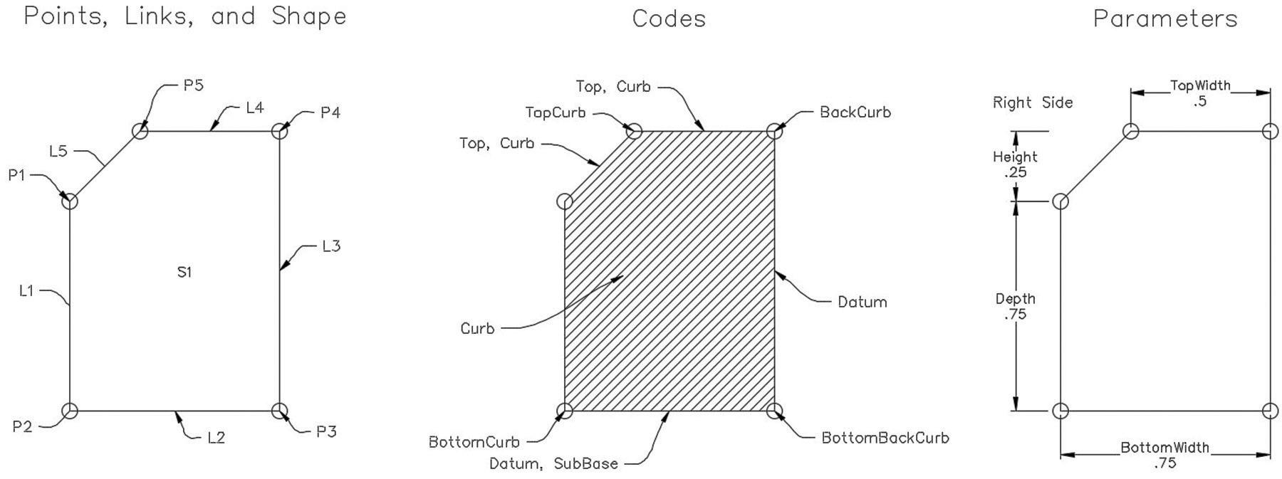
augi.com/augiworld June 2024 | AUGIWORLD Magazine 27 Civil 3D
Figure 1: Subassembly parts
Set Styles, point codes will create feature lines, and links can be used for surface creation
Figure 1 shows the basic anatomy of a subassembly with codes, points, links, and shape. The information found in the help menu for each subassembly gives you more information about each subassembly, shows you its anatomy, the components for which you can override dimensions by using targets, etc. All of this information can help you to reverse engineer these subassemblies, have a better grasp of how they work, and create parametric subassemblies in Subassembly Composer.
As an AutoCAD user, you are accustomed to drawing lines in a very visual way. This makes the way Subassembly Composer works seem a little weird, so when you design a subassembly it is always a good idea to start by drafting an outline by hand.
Subassembly Composer also requires communicating with the program using its own language, almost like coding; in this case it uses .NET framework. All of this will make more sense once we start working with Subassembly Composer in the following exercises.
SLANTED CURB SUBASSEMBLY
Let’s say that you are working on a project that calls for slanted curbs. You open the Tool Palettes and realize that there is nothing there that looks like what you want, so you can’t use any of the existing subassemblies. You can solve this in Civil 3D if you create a closed polyline, turn it into a subassembly, then assign codes, links, and shape and it probably would be fine. The problem is that
if you want to use different dimensions, you would have to create a new one. Instead of doing that, let’s create a parametric subassembly in Subassembly Composer.
The steps below outline the process to create a simple slanted subassembly.
1. Open Subassembly Composer.
2. In the Packet Settings section go to the Packet Settings tab, then in the Subassembly Name field type SlantedCurb. This is the name that this subassembly will use in Civil 3D.
3. Switch to the Input/Output tab; by default the only parameter shown is side, but no default side. Set the side to Right.
4. Click Create Parameter to create a new parameter. The direction is input because it is an input parameter, meaning that the user will input the value.
5. Make sure the type is set to double, which is the type of parameter that will let you input values with decimal figures.
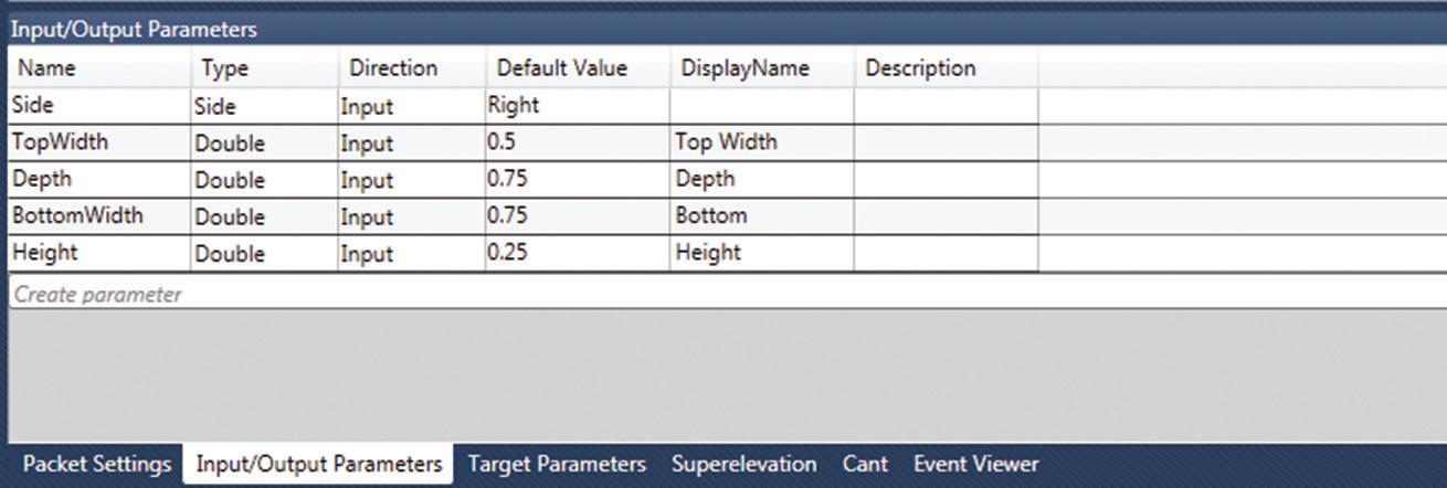
6. Name this parameter TopWidth with no spaces. For display name, type Top Width. The display name can have spaces and that is how it is going to display in Civil 3D.
7. Set a default value for this parameter of 0.5. At this point this value is unitless—the units will depend on the units you use in your drawing.
8. Repeat the previous steps for the other parameters and make sure your parameters match what is shown in Figure 2.
9. From the toolbox under the Geometry category, drag a Point component and drop it into the
AUGIWORLD Magazine | June 2024 augi.com 28 Civil 3D
Figure 2: Input/Output parameters for slanted curb
Flowchart window. This point will be used as the origin and as a reference for positioning the next point. For this point there is no need to modify anything else.
10. Drag and drop another point component. This point will use a point code so a feature line can be created when connecting multiple sections using this subassembly. For point code type “BottomCurb”; make sure you use quotation marks or Subassembly Composer will assume that you are trying to enter a variable.
11. For Point Geometry Type select Delta X and Delta Y. Set From Point to P1, enter 0 for Delta X, and type -Depth for Delta Y. The location of this point will be measured in terms of deltas in the X and Y direction with respect to the origin point. It will be directly below the origin at a distance of negative Depth, which is a parameter previously defined, and no displacement in the X direction. Make sure “Add Link to From Point” is checked and this will create the first link, which will be automatically named L1. For this link there is no need to modify anything else.
12. Add another point element, which will be the bottom right corner of the subassembly. For point codes type “BottomBackCurb.” For Point Geometry Type select Delta X and Delta
Y. Under Point Geometry Properties set From Point to P2 which is the previous point. For Delta X type BottomWidth—in this case it is going to go to the right from P2 so the value would be positive. For Delta Y enter 0. Make sure Add Link to From Point is checked and for codes type “Datum” and “SubBase” divided by a comma.
13. Add another point element, which will be the top right corner of the subassembly. For point codes type “BackCurb.” For Point Geometry Type set Delta X and Delta Y. For Point Geometry Properties set From Point to P3. For Delta X type 0 since there is no horizontal displacement and for Delta Y type Depth+Height. Make sure “Add Link to From Point” is checked and for codes type “Datum.”
14. Add another point element, which will be the top left corner of the subassembly. The point code will be “TopCurb.” Point Geometry Type will be Delta X and Delta Y; it will go from P4, Delta X will be –TopWidth and Delta Y will be 0, in this case it is going to the left from P4 so the X value is. Make sure “Add Link to From Point” is checked and codes are “Top” and “Datum.”
15. The curb subassembly is almost ready—we just need to close it. Add a link component to the flowchart; no need for points here because
augi.com/augiworld June 2024 | AUGIWORLD Magazine 29 Civil 3D
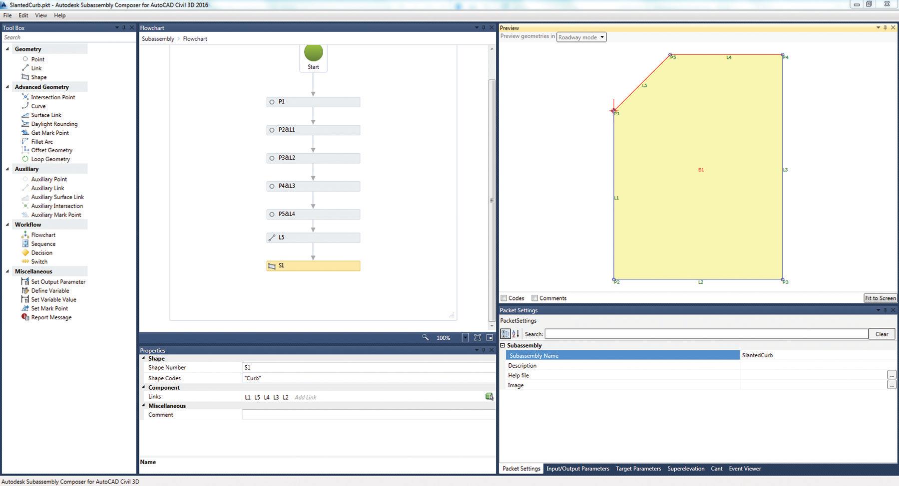
Figure 3: Slanted Curb in Subassembly Composer
the link will connect to existing points. For link codes type “Top,””Curb.” For position, set Start Point to P5 and End Point P1.
16. At this point the subassembly is closed, but it is empty. Drag and drop a Shape component and for Shape Codes type “Curb.” To assign a shape click the green cube with a white arrow in the Links field and then click somewhere inside the subassembly in the preview window.
At this point the subassembly is ready and it should look like Figure 3. You can now save the file and close Subassembly Composer.
17. In Civil 3D press Ctrl+3 to open the Tool Palettes.
18. Hover over one of the tabs in the tool palette, right-click and select New Palette.
19. Name the new Palette Custom Subassemblies.
20. Switch to the Insert tab and from the Import panel select Import Subassemblies.
21. In the Import Subassemblies dialog, browse to where you saved your subassembly and open it. Toggle on Import to and select the Custom Subassemblies palette you just created and then click OK.

AUGIWORLD Magazine | June 2024 augi.com 30 Civil 3D
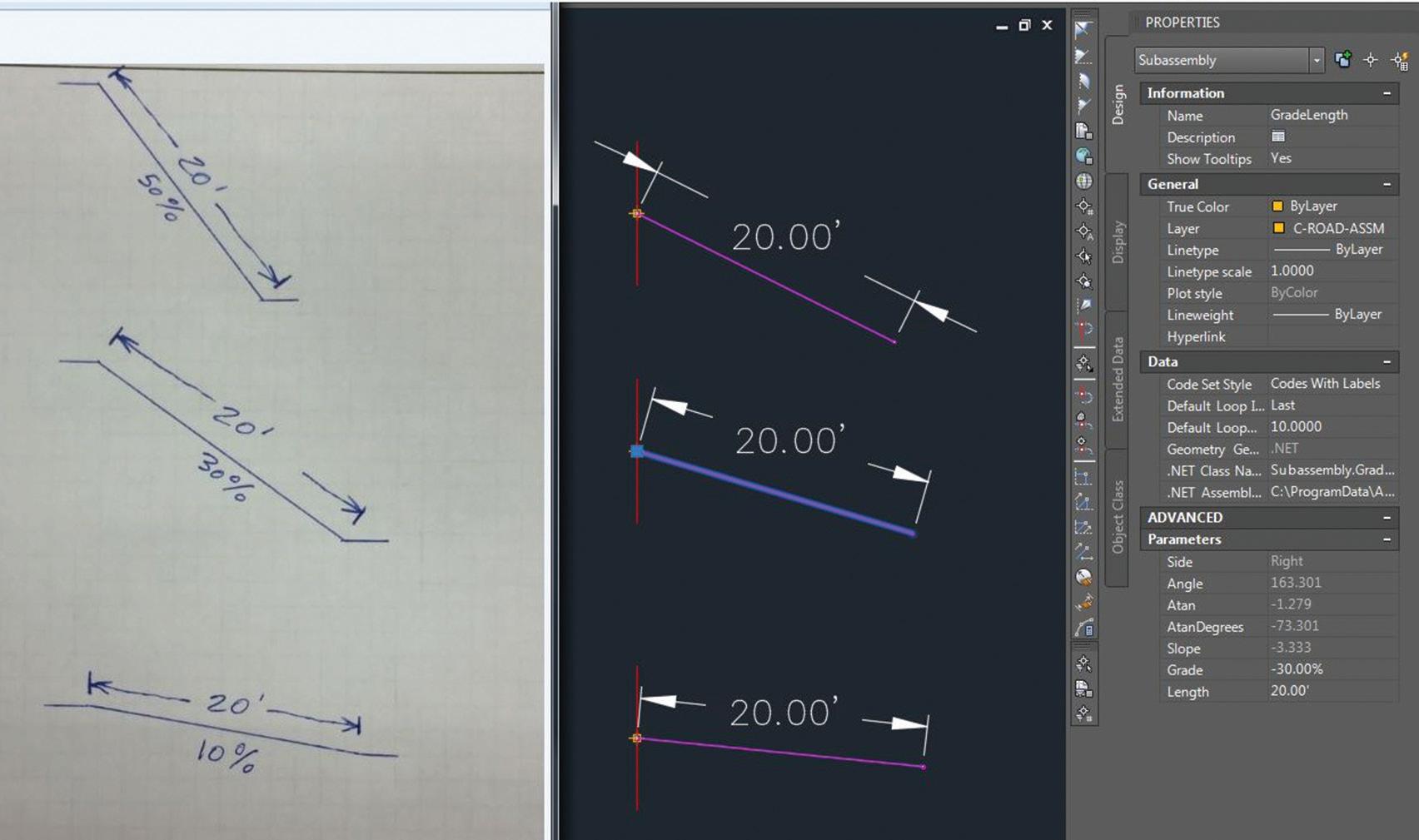
Figure 5: Hand-drawn schematics
Figure 4: Import into Civil 3D
Now you can use the slanted curb subassembly like a regular curb subassembly.
CONSTANT LENGTH AND VARYING SLOPE SUBASSEMBLY
This subassembly works similar to the LinkWidthAndSlope generic subassembly, but this one keeps the length constant regardless of the slope. Figure 5 shows the schematics of what we want to do and how it will look.
1. In Subassembly Composer go to Packet Settings and for Subassembly Name type GradeLength (Figure 6).
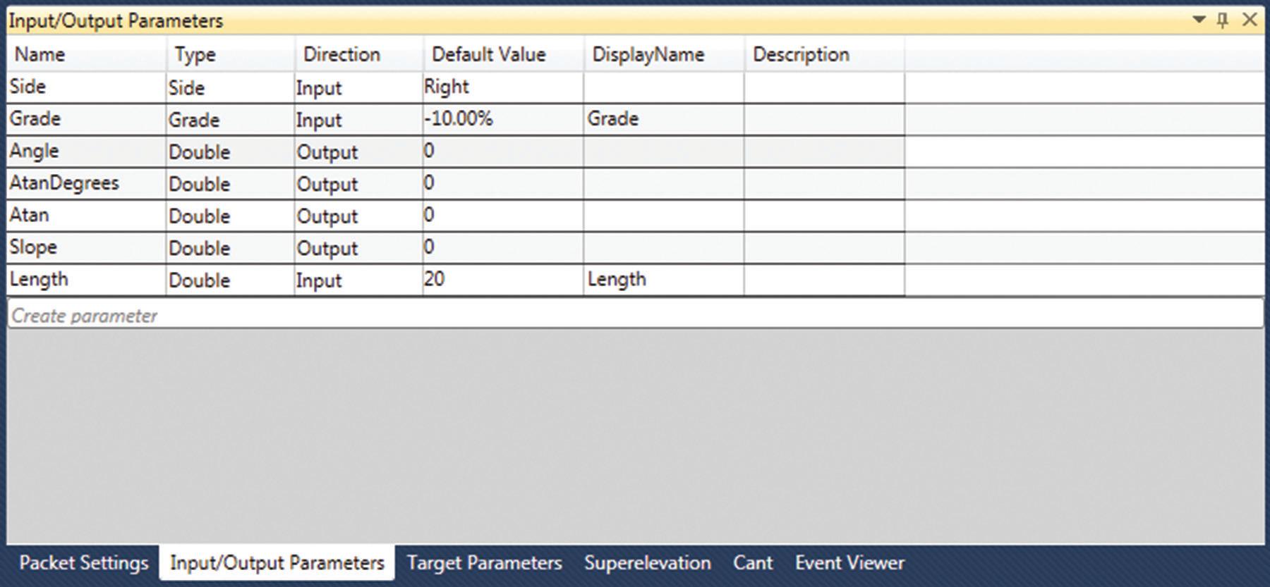
2. Switch to the Input/Output Parameters tab and set the parameters as shown in Figure 6. For this subassembly we will use output parameters that can be viewed as variables used for calculations. Notice that here you have to use both input and output parameters. For the output parameters there is no need to type in a display name because the user will not be able to edit these values. These values are calculated and used for other parameters.
3. Add a point component by dragging it from the toolbox and dropping it into the flowchart window. This will be the origin and insertion point.
4. Add an output parameter. From the toolbox in the Miscellaneous category, drag Set Output Parameter and drop it into the flowchart.
5. Set Output Parameter to Slope, which is one of the output parameters that was created in the packet settings.

augi.com/augiworld June 2024 | AUGIWORLD Magazine 31 Civil 3D
Figure 6: GradeLength parameters

6. For value type 1/Grade. By doing this we are converting the grade value into a slope value.
7. Add another Output parameter from the toolbox. For Output Parameter select Atan and for value, type Math.Atan(Slope); this will give you the slope in radians.
8. Add another Output Parameter. For Output Parameter select AtanDegrees and for value type Atan*180/Math.PI; this will convert the Atan into degrees.
9. Add another Output Parameter. For Output Parameter select Angle and for value type 90-AtanDegrees to find the angle.
At this point you have already calculated all the parameters you need, so now it is time to create a point and a link using those parameters. We want to be able to use positive and negative grade values because depending on that, you will draw something different. And because we have two different options, we will use a conditional operator.
10. From the toolbox, drag and drop a Decision operator, which is in the Workflow category. This will work just like an “If” operator.
11. For Condition type Grade>=0, for False Label type False, and for True Label type True.
Let’s work on what to do if Grade>=0, meaning that the slope is either flat or positive.
12. Drag and drop an Auxiliary point and place it below the True label.
13. For Point Geometry Type select Delta X and Delta Y.
14. For From Point select Origin, for Delta X enter 5 and for Delta Y enter 0. Auxiliary points are used as references for other points and they are not shown in the subassembly.
15. Add a point below the auxiliary point you just created and set its properties as shown in Figure 7.
We just created a workflow for what to do when the grade is positive, but we haven’t created
AUGIWORLD Magazine | June 2024 augi.com 32 Civil 3D
Figure 7: Point properties
one for when it is negative. That is why you can’t see anything yet—because the default grade is negative. Let’s take care of that.
16. Drag and drop an Auxiliary point and place it below the False label. For From Point select Origin, for Delta X enter -5 and for Delta Y enter 0.
17. Add a point below this new auxiliary point. Set its properties the same way you did for the previous point. The point will be numbered P3 and this time the Reference Point will be AP2.
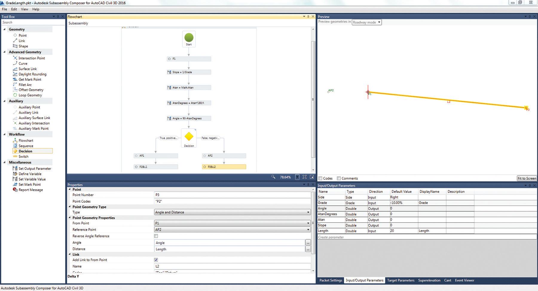
18. Now the subassembly is ready and it should look like Figure 8. Save the file and close Subassembly Composer.
19. Add this subassembly to the Custom Subassemblies palette the same way you did with the other subassembly.
CONCLUSION
Now you have two parametric subassemblies made from scratch. I hope these two exercises shed some light on how to use Subassembly Composer. These subassemblies are rather simple, but I think you can see the potential of Subassembly Composer.
Think about the subassemblies you use when building corridors. Some of them use targets to override slopes, widths, etc. In Subassembly Composer you can also create subassemblies that work with targets. The process is similar in that you have to create parameters and use those parameters to define targets. Now that you know how to use Subassembly Composer, go ahead and create your own subassemblies, draw them in your mind, then on paper, and then build the subassembly. Customize it and make it yours!

Miguel Medina is a Design Engineer at Ensign Engineering. He has worked in infrastructure design, urban planning, road design, site development, geographic information systems, facility management, and construction management. He also worked as a research assistant in environmental projects and software development for software used in civil engineering while in school.
augi.com/augiworld June 2024 | AUGIWORLD Magazine 33 Civil 3D
Figure 8: GradeLength subassembly
Tagis: Revolutionizing Field Access to Critical Project Information
OVERVIEW
In the realm of civil engineering and design, accessing vital project data in the field can often pose significant challenges during the planning stages. However, with Tagis, these hurdles are swiftly overcome. Tagis offers a groundbreaking solution that seamlessly integrates your design with cuttingedge technology, making it effortless to access critical information directly from your mobile device or tablet.
TAGIS TECHNOLOGY: BRIDGING THE GAP BETWEEN DESIGN AND FIELD OPERATIONS
At the core of Tagis is its innovative use of GeoAnchored data, harnessing the wealth of information already embedded within your Civil 3D model. This data is seamlessly transmitted to the Tagis platform, where it is transformed into an immersive augmented reality experience accessible through your mobile device.
KEY FEATURES AND BENEFITS
• Real-World Metaverse: Tagis creates a private realworld Metaverse, overlaying a hidden global layer of information onto your physical surroundings. This innovative approach enhances the productivity and efficiency of frontline workers
by providing them with instant access to the information they need, right when they need it.
• Enhanced Visualization: With Tagis, complex project data is no longer confined to the digital realm. Through the power of augmented reality, users can visualize critical design elements in their real-world context, enabling better decision-making and problem-solving in the field.
BETA TESTING PHASE
While Tagis is currently in its beta testing phase, you can experience its transformative potential firsthand by requesting credentials to access the platform for free. This presents a unique opportunity to explore the capabilities of Tagis and provide valuable feedback to shape its future development.
CONCLUSION
Tagis represents a paradigm shift in the way we interact with project data in the field. By seamlessly integrating design information with augmented reality technology, Tagis empowers frontline workers to thrive in their environment, armed with all the information they need at their fingertips. Embrace the future of field access with Tagis

Please let us know if you have some news to share with us for future issues. Likewise, we want to know if you are a featured product or news item user and would like to write a review. We’d love to hear from you!
AUGIWORLD Magazine | June 2024 augi.com 34 Inside Track by: Marco Oregon

AUGI Members Reach Higher with Expanded Benefits
AUGI is introducing three new Membership levels that will bring you more benefits than ever before. Each level will bring you more content and expertise to share with fellow members, plus provide an expanded, more interactive website, publication access, and much more!
Basic members have access to:
• Forums
• HotNews (last 12 months)
• AUGIWORLD (last 12 months)
DUES: Free
Student members have access to:
• Forums
• HotNews (last 24 months)
• AUGIWORLD (last 24 months)
• AUGI Educational Offerings
DUES: $2/month or $20/year
Professional members have access to:
• Forums
• HotNews (full access)
• AUGIWORLD (full access and in print)
• AUGI Library
• ADN Standard Membership Offer
DUES: $5/month or $50/year
Are you ready to upgrade yourself and your membership? Access additional benefits and upgrade at www.augi.com


AUGIWORLD Print AUGI HotNews Digital Visit www.AUGI.com/advertise Connect with AUGI Members Increase your revenue by advertising with AUGI and reaching its 400,000 Members. AUGI.com Website Thousands of visits per month Forum Advertising Active membership participation • Advertising Email Blasts • Targeted Mailings • Industry Leading Google Results Site US $8.00 The Official Publication of the AUGI Design Community Diamond Sponsors Implementing Best Strategies Automating Punch Lists with Bluebeam Revu Setting Up System Variables for Success in AutoCAD AUGIWORLD Also in this issue: