

AUGIWORLD
3rd Party Apps



From the President

HELLO AUGI MEMBERS,
It’s been a crazy couple of months since my last AUGIWORLD Magazine President’s Letter, and a lot has happened since. I am sure you are thinking to yourself, what has happened, Eric? Glad you asked! The birth of the AUGI annual user conference was born… AUGI CON 24 (AC24).
AC24 is a user conference based on our motto of ‘users helping users’, and that was evident by all of our presentations and discussion panels which were loaded with practical, real-world tactics and advice that after attending those respective sessions you can take what you just learned and apply it to your job right then. With that said, AC24 was a really big hit, and we couldn’t be prouder of the event and the impact it’s having on the industry and all the feedback we are receiving.
We had over 1000 people register for this special two-day event across 48 countries. We have been watching and listening closely to what’s going on in the industry, and we knew if we held a user conference that it would be well received, and we were right!!
We are super happy we bet on ourselves and that we are filling a hole in the market in helping the industry grow without any underlying agenda besides trying to help others beyond just a singular software platform as AUGI is now software agnostic in what we support and talk about.
Again, thanks to all the AC24 presenters, discussion panel guests, and moderators along with the AUGI staff that worked behind the scenes for months to get this off the ground. The success of our inaugural AUGI CON event could not have been possible without all of you that attended. Thank you for taking the time out of your busy schedules to attend.
In this month’s AUGIWORLD Magazine articles, we are focusing on 3rd-Party Applications. 3rd-Party apps are essential in CAD/BIM production workflows, providing specialized features that streamline processes, automate tasks, and enhance productivity. By integrating these apps, CAD/BIM professionals can customize their workflows, improve collaboration, and achieve more precise and efficient project outcomes. As the CAD/BIM landscape continues to evolve, embracing these tools will be crucial for staying ahead in the industry.
I hope you enjoy this month’s issue and a big thanks to all of the Authors that have contributed an article this month.
Until next time…
Eric
AUGIWORLD
www.augi.com
Editor
Editor-in-Chief
Todd Rogers - todd.rogers@augi.com
Copy Editor
Isabella Andresen - isabella.andresen@augi.com
Layout Editor
Debby Gwaltney - debby.gwaltney@augi.com
Content Managers
3ds Max - Brian Chapman
AutoCAD
Civil 3D - Shawn Herring
BIM/CIM - Stephen Walz
BricsCAD - Craig Swearingen
Electrical - Mark Behrens
Manufacturing - Kristina Youngblut
Revit Architecture - Jonathan Massaro
Revit MEP - Jason Peckovitch
Tech Manager - Mark Kiker
Inside Track - Rina Sahay
Advertising/Reprint Sales
Kevin Merritt - salesmanager@augi.com
AUGI Executive Team
President
Eric DeLeon
Vice-President
Frank Mayfield
Treasurer
Todd Rogers
Secretary Kristina Youngblut
AUGI Board of Directors
Eric DeLeon
KaDe King
Chris Lindner
Frank Mayfield
Todd Rogers
Scott Wilcox
Kristina Youngblut
Advisory Board Members
Shaan Hurley Shelby Smith
Publication Information
AUGIWORLD magazine is a benefit of specific AUGI membership plans. Direct magazine subscriptions are not available. Please visit www.augi.com/account/register to join or upgrade your membership to receive AUGIWORLD magazine in print. To manage your AUGI membership and address, please visit www.augi. com/account. For all other magazine inquires please contact augiworld@augi.com
Published by:
AUGIWORLD is published by AUGI, Inc. AUGI makes no warranty for the use of its products and assumes no responsibility for any errors which may appear in this publication nor does it make a commitment to update the information contained herein.
AUGIWORLD is Copyright ©2024 AUGI. No information in this magazine may be reproduced without expressed written permission from AUGI. All registered trademarks and trademarks included in this magazine are held by their respective companies. Every attempt was made to include all trademarks and registered trademarks where indicated by their companies.
AUGIWORLD (San Francisco, Calif.) ISSN 2163-7547




ComfyUI, Stable Diffusion, and 3ds Max
This month, we’ll introduce how newer AI technology is used with 3ds Max to generate some interesting content.
In the evolving landscape of artificial intelligence and machine learning, user-friendly yet powerful tools are paramount. That is where ComfyUI, a graphical user interface (GUI) and a backend designed specifically for Stable Diffusion models, is introduced. ComfyUI revolutionizes how researchers, developers, and artists interact with these complex models by providing a modular, node-based approach that enhances usability and functionality.
WHAT IS COMFYUI?
ComfyUI is an innovative platform that offers a visual and intuitive way to work with Stable Diffusion models, which are crucial in various applications, including image generation, noise reduction, and data prediction. ComfyUI’s appeal
lies in its node-based workflow, where each node represents a different function or operation within the diffusion process. This visual approach allows users to construct, modify, and optimize their models with the clarity and ease that traditional coding interfaces lack.
Key Features
Node-Based Workflow:
The node-based system of ComfyUI is its standout feature. Users can drag and drop nodes to create complex workflows, connecting them to a coherent process. This visual representation of data flow and operations demystifies the model construction process, making it accessible even to those with limited programming experience.
Modularity:
ComfyUI’s modular design allows users to combine different components and techniques to suit their
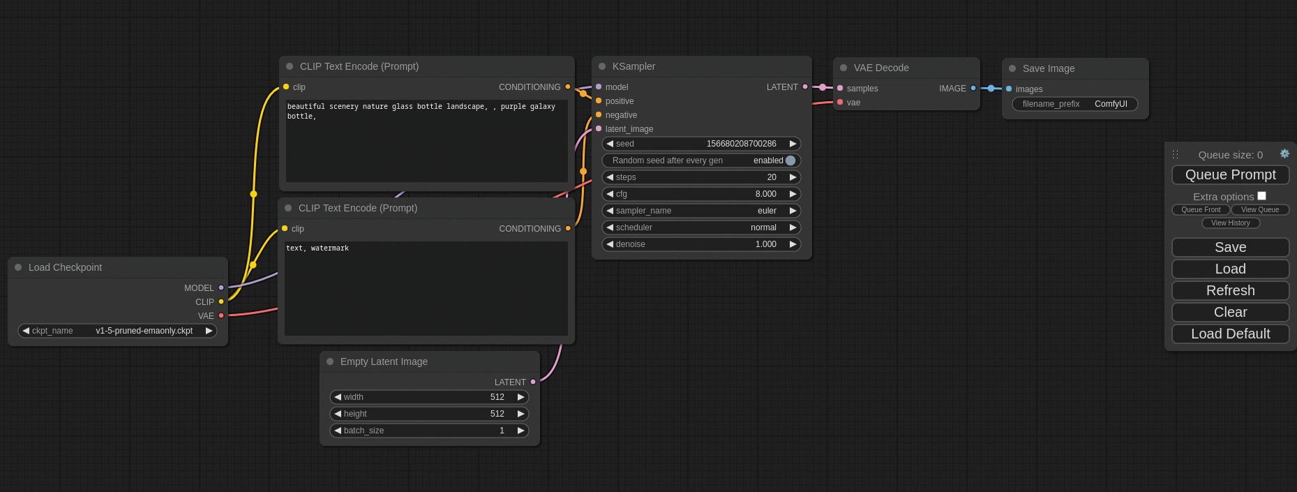
Figure 1: ComfyUI Node Network
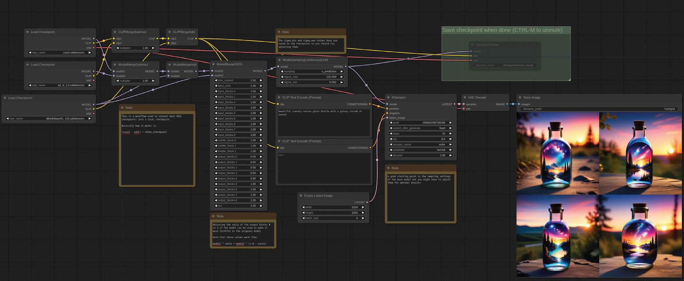
needs quickly. Whether you’re working on image enhancement or predictive modeling, ComfyUI allows for a high degree of customization and flexibility. Here are some examples generated by various users for their specific needs.
There are many examples on their Github site and others like them. These examples range from creating high-quality cartoon characters from children’s stick figure drawings to producing 360-degree rotations of an object in a 2D image/ photograph- each generated from users’ experimentation in building their stable diffusion models and node networks.
Comprehensive Backend Support:
Beyond its GUI, ComfyUI provides robust backend support to manage the computational demands of Stable Diffusion models. That includes efficient data handling, model management, and optimal resource allocation, ensuring smooth and effective operation.
Customization and Extensibility:
One of the significant advantages of ComfyUI is its ability to be extended through plugins and custom nodes. This feature allows users to tailor the interface and functionalities to their requirements, making it a versatile tool for various applications.
Enhanced Visualization and Debugging:
The visual nature of ComfyUI not only aids in creating workflows but also significantly enhances
debugging and optimization processes. Users can visually trace data flow and operations, quickly identifying bottlenecks and errors.
ENTER 3DS MAX
Combining ComfyUI’s stable diffusion with 3ds Max lets users generate concepts quickly. Take this example in Figure 3, created by Yannis Efstathiou on YouTube (https://youtu.be/pNyIp73zva8?feature=shared) in realtime. As Yannis rotates the view, the stable diffusion/ model updates dynamically.


Brian Chapman is a Las Vegas 2D/3D design professional who creates content for the AEC industry, games, film, entertainment, education, simulation, training, and software development. Brian can be reached at procadman@procad.net.
Figure 3: 3ds Max with ComfyUI and Stable Diffusion
Figure 2: ComfyUI SDXL Example

Manager
Myopia
When I was about 20 years old, I started working on a drafting board as a draftsman and technical illustrator back in the day, before computers helped get the job done. Soon I needed glasses as my distance vision started getting fuzzy. I could see close-up, but not down the road. Myopia is the technical term for being nearsighted; also called short sightedness. It is a condition of the eye that causes close objects to appear clearly, but things that are farther away are fuzzy. I have this condition and on my driver’s license the little box is checked that says I must wear corrective lenses to help me see objects that are far away.
The Tech Manager, while needing to work on the immediate needs of staff and tech, can become overly shortsighted. While things appear clear for them in the short-term, longer-term issues and planning seem to not come as easily. It is easy to get trapped in the daily grind of issues and troubles that come at you from every angle. There are challenges to finding the time and brain power to look into the future.
I have written on Strategic Planning and a lot of skills needed for thinking long-term are defined in those articles. Those articles presented a more formal process, but this article will be more about the informal and the mindset or framework that must be in place to make sure that you are balancing the tyranny of the urgent, while also keeping in mind the need of having a view of the broader scopes and longer timelines. Let’s take a quick look at how we can encourage ourselves to have a better view into the distance.
THINK ABOUT IT
The first thing needed might be just more time to think long-term. If you are caught in the cycle of running from one fire to the next, you have little time to look down the road. I know that things can pile on, but there will be opportunities to take a brain break and just think about what might be possible. It could be a lunchtime walk or getting up a little earlier. It might be the drive to and from work. If you are trapped by your calendar, then
use it to plan in some thinking time. Make an appointment with yourself and keep it. You may want to downgrade your meeting requests by shorting the meetings you have by 15 or 30 minutes. Recapture the time and use it to think. Google has a culture that encourages employees to spend 20% of their time on something outside their regular job duties. While most of us could never take that much time, maybe start with two percent. That is just about one hour per workweek that you could set aside to step out of your usual duties and think about what might improve your firm, your processes or yourself.
GET CORRECTIVE LENSES
Ask others for input. Without advisors, even the greatest planners and doers get into trouble. The corrective lenses of seeing things from another person’s perspective can bring clarity. Start talking to others and get their feedback. Ask them what they think of the next tech innovation. Attend a tradeshow or event and listen to what others are doing and predicting. Read more. Input from others, who are also long-term thinkers, can expand your understanding and make the blurry future a little clearer.
LET YOUR VISION REST
Just like when your eyes are strained it get harder to focus, your management focus can become blurry if it is overworked. Take some time to rest your long-term efforts and let them stew a little. There is always some wisdom in “sleeping on it”. Letting some time pass when you do not actively work on seeing the future, but let it unfold a little more before making a move. I have set aside plans and, during that down time, come up with a clearer vision of what should be done. Sometimes you just need to let the marinade work itself into the meat.
LOOK AT THE DISTANT HORIZON
Just like avoiding eye strain, you need to extend your focus beyond your desktop. You may follow the American Association of Ophthalmology’s 20-20-20 rule when you feel that you have been staring at your monitor too long. It suggests that you take a 20-second break to look at something 20 feet away every 20 minutes. I usually look out the window and focus even farther away. I can tell when I don’t give myself a visual break and at the end of the day my distance vision is kind of blurry.
In the workplace, it can mean that you remind yourself to think farther out. If the solution you have to a problem will work for the next week, pause and think about what it would look like in a month. If the software upgrade will solve this month’s problems, pause and think about what it will be like in a year. If the hardware is good enough for a year or two, look to see what the cost would be for something that will last even longer. Keep pushing your time horizon and thinking out.
Push out the scope and impact also. When thinking of a change, think about what it would mean if everyone in the firm did this. What might work good for a small team may not expand well to everyone. Or maybe the transition for the most adept workings will slow for those who need more training. Think about what would happen if everyone started this or stopped that. It might make you think a little more.
By always expanding your timelines, impacts, areas of concern and planning out beyond the near term, you can start having a better grasp on the needed focus for good long-term thinking. You must take care of the day to day, but it is always a balance between the immediate and the farther reach of your oversight.

Mark Kiker has more than 35 years of hands-on experience with technology. He is fully versed in every area of management from deployment planning, installation, and configuration to training and strategic planning. He is an internationally known speaker, writer and former AUGI Board member and president.
Mark is currently serving as Chief Technology Officer for SIATech, a non-profit public charter high school focused on dropout recovery. He oversees two web sites, www.caddmanager.com and www.bimmanager. com. He can be reached at mark.kiker@augi.com and would love to hear your questions, comments and perspectives.
AutoCAD Drawings & PDF Files – A Perfect Combination

AUTOCAD DRAWING FILES AND PDF’S –WHAT A TEAM.
AutoCAD’s DWG format is universal, easily imported into many popular design software packages. Often, however, the data we would like to bring into an AutoCAD DWG is in a format which is native to other software packages.
I am an opportunistic CAD designer; I will admit it. If I can get CAD data on something that is needed for my drawing from an external source, I will certainly do so (with a degree of caution, of course). Commonly, when looking for drawing data on a component or device that will be used in a design,
the first thing that a designer will look for is native AutoCAD in format.
Native DWG files as well as DXF files are available when searching many vendor websites. Care must be taken when working with the available files. Often, vendors do not actively support 2D formats. If they do, the file is often a converted 3D file, which is a completely different animal.
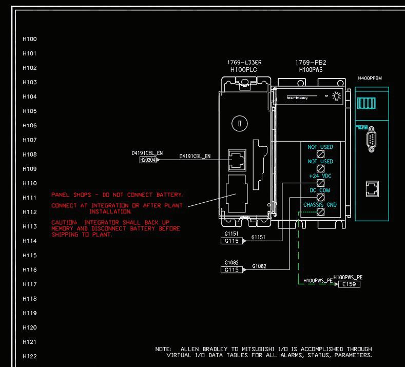
The screenshot below looks like a typical 2D drawing of a PLC. Things are not what they seem, however. I imported the module on the left from the vendor website. The vendor took a 3D component and created a 2D DWG.
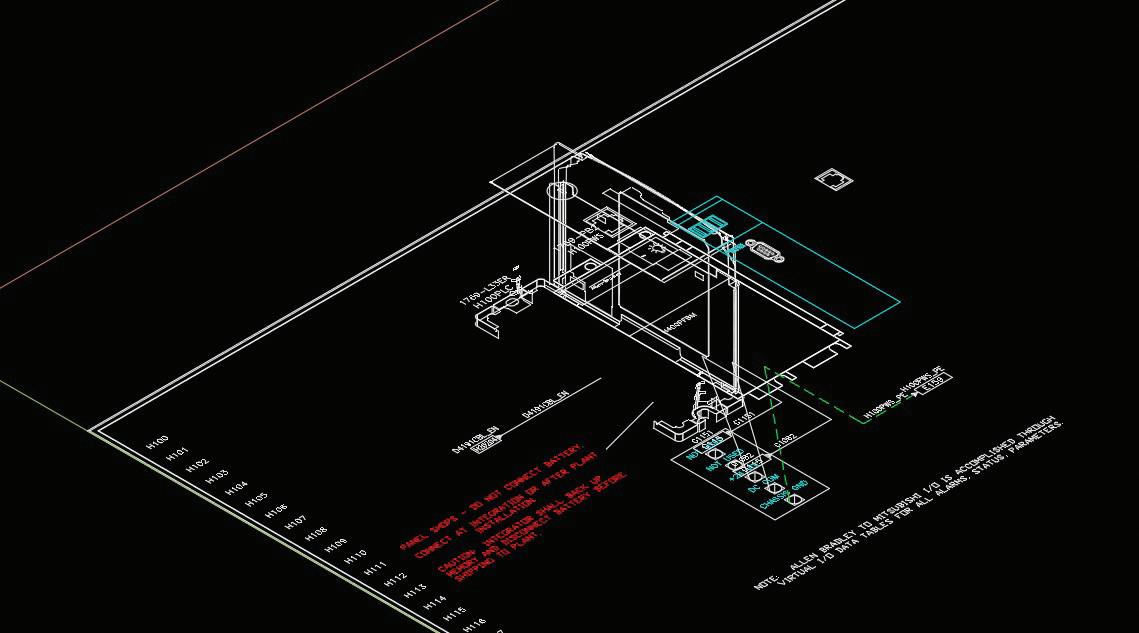
As I went to add wires and connections to this drawing, I found a few hidden “bonuses,” as seen in the screen shot below.
*TIP* when you suspect that a DWG has 3D embedded in it, click on the home icon of the view cube – you may be surprised!
As the screenshot below shows, the vendor data had a few extras included! The captured data which, when visible from this perspective, is obvious, had caused a few challenges. Notice how the wires to the terminals are not parallel to the drawing border. Also, trying to mate components with this data can be challenging when I have several end points that can be selected erroneously.
AutoCAD
This detail was edited to attempt a clean-up of the drawing, without much success. I have since taken a different approach to the importation of vendor data when I need to include a component, as this unseen data also adds to file size and drawing complication.
PDF’S – VALUABLE SOURCES OF DATA IF YOU DO A LITTLE DIGGING.
PDF data is a treasure trove of information available to the CAD designer. It is available in many locations, some of which people frequently overlook. Think about how many documents a vendor includes image data in. Everything from cut sheets to full manuals for components, and recently as a link to the file on the vendor website.
There are some vendors who will configure their PDF data in a way that makes image data unavailable, I have found, however, the number of them is low.
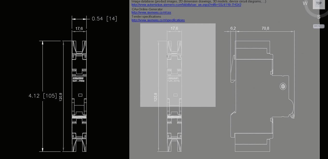
Product manuals are a great place to get clear and accurate data for my drawings. The images typically included are basic, allowing component wiring, yet providing enough detail to easily identify a component. The screenshot below is a prime example. I have enough data for the component to be clearly identified, yet I can do all my design work with the included data.
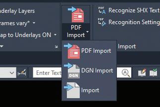
A word of caution when working with this data is the scale factor. Manuals, as well as product cut sheets are formatted to fit letter size paper. In the image below, the breaker is 17.6mm wide by the dimension showing. This size restriction applies to any size component! When using this image as a PDF import
it will be (obviously) out of scale. The screen shot below is how the PDF came into my drawing.
The dimension is referenced in metric. This is not really an issue, as you will need to scale it anyway. However – take note of the dimensions that I put on the copied data. Doing the math, the view is drawn at .78 = 1 scale, if you have your dimension style properly set. Before working with this data, I recommend doing a “distance” command to verify the actual size of the entity. Using this data, you can determine how to accurately scale the entity to match the drawing settings.
Another point to remember is that the data will contain many small entities, in this case 173 of them. If you miss a line or two this could be interesting.
*TIP* - always select the desired portion of the detail and “cut with base point” using a practical base point. This will remove the individual pieces from the drawing, and provide a practical base point. Next “paste as block” back into your drawing. One entity is a great thing…
When this single entity is selected, it can easily be manipulated without losing important detail. I will typically save my original PDF unedited, to our server to preserve all the data. When insetting into a DWG, edit the scaling and detail content you wish to keep. Also add a note to the original file with the proper scale, for future reference!
By creating a reference directory of original data files, and an alternate for cleaned up data , the source data can always be referenced as necessary.
PDF’S – NOT JUST ONE TRICK PONIES.
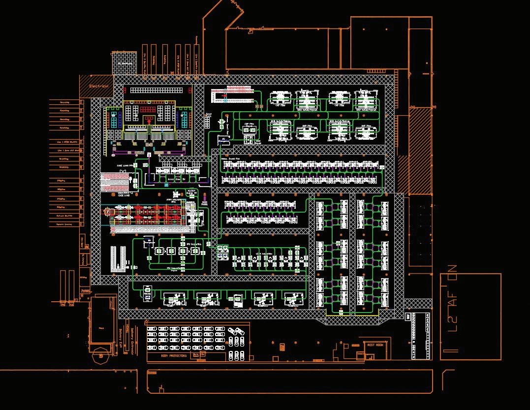
As often as I use a PDF reference in my schematic design and enclosure design, the benefits of including a PDF extend to many other aspects of my design work. As part of my work, I need to add track data for our AGV integration into a plant. As customers are sometimes hesitant to send me a DWG, they will send a PDF. I will then put this into my file as an import, cleaning up the layers and locking them to avoid errors.
One of the caveats of PDF imports is the uncertainty of the layer structure.
In the image above, the plant layout is a PDF import. I will typically lock its layers for accuracy.
CONCLUSION
As a CAD designer, I am always looking to save time on my work. PDF files and their proper handling can make a designer more efficient and accurate. Too often the sources of said files get overlooked, resulting in extra time and work.
Always check online, and not just the vendor’s website, for a PDF manual or cut sheet before you invest too much time and start from scratch on a project.

My current employer designs Automated Guided Vehicles (AGV’s) and test machines. I have worked with AutoCAD software for forty years, starting on version 1.4. Having been with my current employer for almost sixteen years and CAD manager by necessity for at least ten, I have seen their culture change many times in attempts to improve processes and become more efficient. CAD standards have become a high-profile topic recently. I am excited to share my process of implementing a user-friendly system of CAD standards with others.
Essential Revit Add-ins for MEP Professionals

Ihave been using Revit since 2007 and various add-ins have been essential aids in our daily workflows. Without them some of what we did/ do now, could not have been completed. Even though AUGIWorld has a dedicated section every month called Inside Track, currently written by Rina Sahay and is dedicated to 3rd Party Add-ins for Revit, AutoCAD and various other BIM software, our July issue is all about 3rd Party Add-ins. Make sure you check it out every month. Both Rina and the previous author, Shaun Bryant, may have covered some of the essential add-ins that I will be discussing here in past issues. I will showcase how these add-ins help with my everyday workflows as a BIM Manager so let’s jump right in.
KEYNOTE MANAGER
Keynote Manager, created by Steve Faust at Revolution Design, is probably one of the first Revit add-ins I used when I first started using Revit. At the time, we were looking for a way to utilize the same notes across various sheets. After doing some research and trying numerous workarounds, I found Keynote Manager. It was developed as a better version of the “out of the box” Keynote functionality in Revit for Architecture/Structure. It is great at what it was created for, but for MEP, it did not do so well. We still gave it a go and I developed a strategy to use it for MEP. Our system was to have different sections of notes for each discipline with a specific letter for that discipline to separate the notes since the Key Value cannot be the same. I still use a variation of that method to this day as seen in Figure 1.
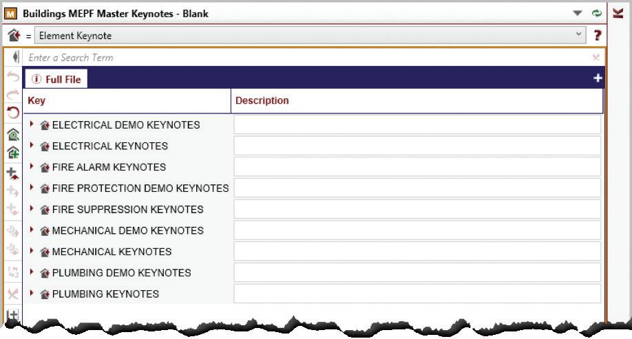
Figure 1 - Master Keynotes
I was constantly breaking the tool and having to reach out to Steve for fixes or workarounds and as an independent developer, he was great at getting back to me and fixing the things I broke. In fact, he is still that way today. Thank you, Steve, for putting up with all my antics over the years.
We recently started using a Master Keynote file that houses several hundred notes that can be “imported”, for lack of a better word, into a projects Keynote file and renumbered as needed. This newish functionality in Keynote Manager has been a game changer for us using the same notes on all projects. Apparently, this feature has been available since version 13.5, and we are on version 20 now. Guess I was living under a rock when that dropped, oops. If you are creating keynotes in Revit, then you absolutely should be using Keynote Manager!
CTC SOFTWARE – BIM PROJECT SUITE AND BIM MANAGER SUITE
I have also been using this suite of tools for quite a long time as well. Probably just as long as I have been using Keynote Manager. There are a lot of tools within each suite and over the years a few new ones have been added that I am using today. Back in the day, before the cloud was a thing, we used to do weekly/bi-weekly model exchanges. One tool
that I used all the time during these ancient times was the Project Cleaner from the BIM Manager Suite. This tool, at the time, was invaluable for our projects. Now that all of our projects are in the cloud, this tool has been “retired” for me.
SPREADSHEET LINK
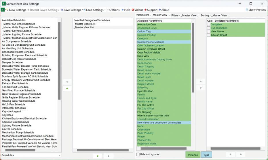
This tool was created to give you the ability to export your Revit Schedules to excel, have someone without Revit access manipulate the data outside of Revit and then import it back into the model. I, however, do not use it for this. I use it an entirely different way. Most of us are aware that editing schedules in Revit can be time consuming. I use Spreadsheet Link (SL) to quickly rename/renumber our sheets and views during our Model Setup process. When using SL in Revit, it gives you an Excel looking dialogue. In the SL settings you will see I have a Master Sheet List and Master View list created in our Starter File that I open here. After adding the schedules to In the SL After unlocking it (not sure why this is still a thing though), I use Excel functionality to copy/paste information between lines or drag the information down, so it renumbers it. I also use Find/Replace to change out information like Level 1 to First Floor or something similar. This has saved me countless hours across a multitude of projects over the years.
SCHEDULE XL
While this tool also works with Excel Schedules, instead of being a round trip of information, this is a one-way trip of data from Excel to Revit. When imported, you can create a schedule or a drafting view. When creating a schedule from Excel, the settings allow you to change how that looks so these imported Excel schedules look and feel more like a native Revit schedule. With either a schedule or drafting view, if that data is updated in its original Excel format, it can be reloaded and updated in Revit. It will also automatically update when the project is first opened. This is a great tool when you have something like a Matrix or some other complex schedule that is not easily recreated in Revit.
SHEET ASSISTANT
This is a fairly new tool that came out a few years/ versions ago and I use it for every single model I set up. I even wrote it into the documented process that I developed for others to use when they set up our models. As a long-time BIM Manager, I pride myself on consistency across disciplines. When MEPF is in the same model, which has been the
norm for quite some time, I want to be able to “flip” through the sheets and have all the views, notes, etc., lined up in the same exact location. I do my best to make sure these views line up with our clients’ (typically architects) views as well. There have been some projects where that was not the case though. Our standard is to have at least 5” of blank space on the right side of the sheet for General Notes, Keynotes, Legends and Keyplans. Since Architect’s have dimensioned plans with Gridlines, those dimensions and extended gridlines impede on that 5” of blank space from time to time. Our gridlines extend to about 5’ outside of the building on the farthest wall and if the view placement, even with those shortened gridlines, I will move our views to the left on the sheet to accommodate the minimum space of 5”.
Using this tool is super simple. You will need to set up a sheet how you want it to look. How you do that is completely up to you. I either use a detail line from grid intersection to Title Block corner or reference lines when no grids are present. Once your sheet is set up, you use it as a template to place the views for the other sheets in the same place. Select the template sheet and then select the sheets you wish to use the same view placement.
Figure 2 - Spreadsheet Link Settings
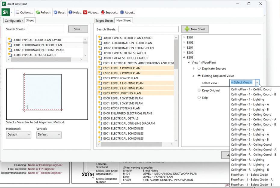
With the sheets selected, you just go down the list, selecting the “existing unplaced view” and selecting the view from the drop-down menu. Make sure the radio button is filled in, otherwise the view won’t be placed when you hit apply. If you have views placed in different locations on the sheets, you will need to repeat this for every view that is different.
The key to getting the views to line up using Sheet Assistant is to have similar views cropped the same way (recommended to use scope boxes) and to have no sections placed on the views.
VIEW CREATOR
Our starter file has two floor levels and a roof with all the discipline-specific views we use that work for most of our projects. If these three levels are not enough, I will use View Creator to create additional levels and all the necessary views for the project. When creating additional views, you select the level associated with the view, select all the view templates you want to create views from, the views phase and the scope box you want to use for the
view. Make sure you give the different sections an abbreviation that matches your view naming standards and add them to the bottom before hitting create views.
Besides creating additional levels and views, View Creator does a few other things that I have not particularly used but could be useful for some of you reading this.
• Elevation, Section and Detail Creation
• Dependent Views – create dependent views utilizing scope boxes
• 3D Views – create 3D views based on view templates
• Schedules – duplicate schedules by level or phase
• Sheets/Title Blocks – view and control Title Block usage
• Worksets – create 3D views for specific worksets
Figure 3 - Sheet Assistant Workflow

• Duplicate Views – allows mass/repetitive duplication of multiple views
• View Templates – drag and drops views to assign view templates
SHARED PARAMETER MANAGER
Wow, this tool has been a tremendous help for me when managing the Shared Parameters for all the companies I have worked for since I started in this industry. It allows me to create custom parameters within any of the custom parameter groups we have. I can easily move them from group to group if need be or I can make a selection set of parameters
5 - Shared Parameter Manager Dialogue
to load into a project or family. I have tried other Parameter Management tools and I always find my way back to this one.
There are a few other tools that I use from CTC Software, like Type Swapper, Import/Link Manager and Family Processor that I won’t be discussing here so I can talk about some other handy tools for my daily workflows.
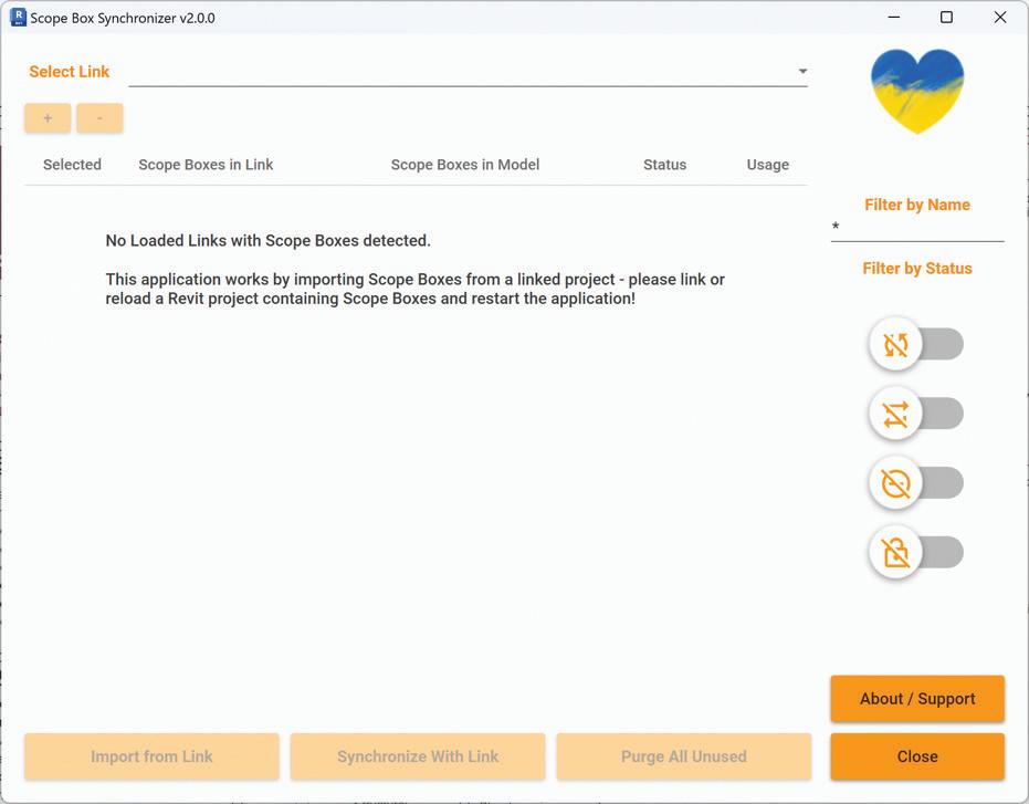
SCOPE BOX SYNCHRONIZER
I found this handy little free tool from Omnia Revit on the Autodesk App Store many ions ago. It looks at any links you have and your model and will bring those Scope Boxes into your model from the linked model with the click of a button. When you run the tool later, it will tell you if those scope boxes are out of sync with the linked model and allow you to fix that. Version 2.0 from the end of 2023 has a new UI that I am eager to try out because my work computer still has an older version installed. If you are using Scope Boxes between models, this is a must-have tool.
PYREVIT
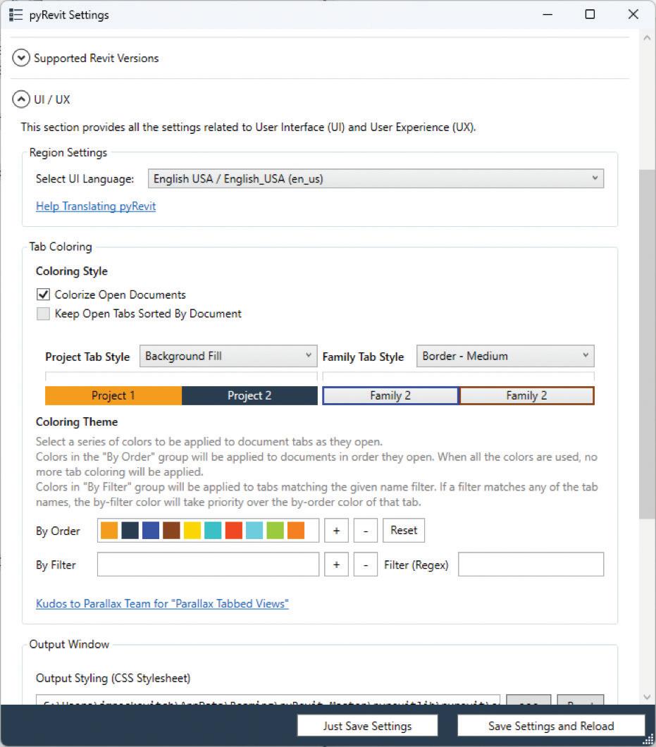
Now pyRevit has been featured several times before within the pages of AUGI World but how does it help with my workflows? Out of all the tools built into pyRevit there are a few that I use all the time. The first being the option to turn on Colored Tabs
Figure 4 - View Creator Dialogue
Figure

for the UI. Now this might not be important to you, but this helps me visually determine which tabs belong to the same project or family.
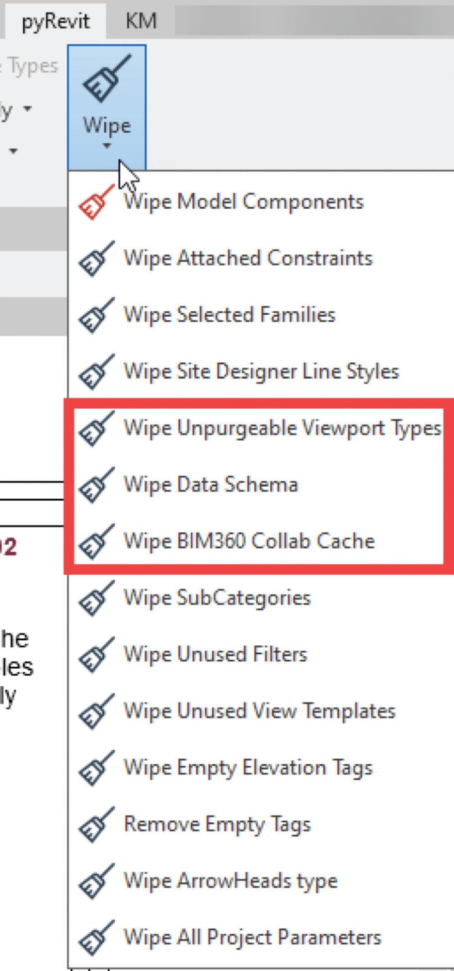
The second being a few of the Wipe Commands: Wipe Unpurgeable Viewport Types (for those pesky random viewport types that randomly show up in our projects), Wipe Data Schema (been using that a lot lately because of Schema conflicts in 2024), and Wipe BIM360 Collab Cache (nice single button to clean out some space on the HD and corrupt local files).
ARROWHEAD ASSIGNER
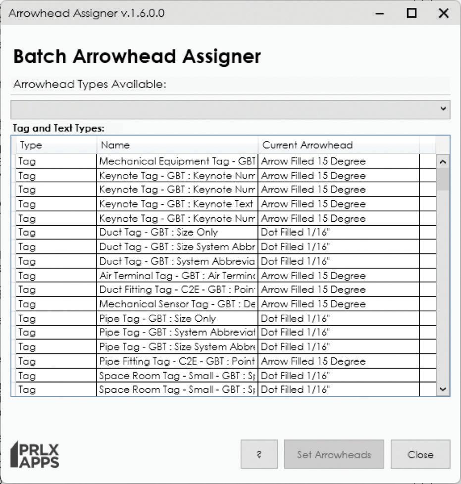
From Parallax Team, this tool allows you to batch update the arrowhead type being used by your tags, text types and annotations. Having to do this one family type at a time was a huge chore. Now that I can do this in a matter of a few minutes, I will never go without this tool again.
Figure 6 - Scope Box Synchronizer
Figure 8 - pyRevit Wipe Commands
Figure 7 - pyRevit Colored Tab Settings
PREVIEW IMAGE GENERATOR (P.I.G.)
When it comes to creating preview images for Windows in File Explorer, it’s absolutely horrid. For the Revit families, this is especially the case. The native way these are created makes it impossible to tell what most of the content looks like when you set File Explorer view to any of the Icon options. PIG as I call it, it even has a PIG in its logo, is here to save the day and create crisp, clean and easily identifiable thumbnail previews for your Revit families. These thumbnails are used in various locations involving Revit from file explorer, opening a Revit family or a Content Management Solution. More on the latter later.
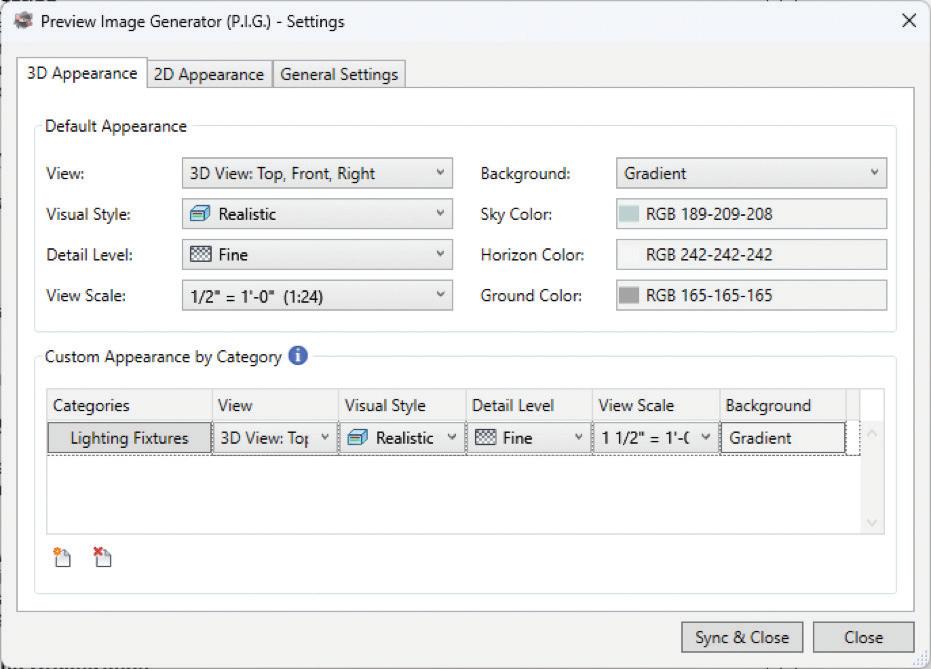
Figure 9 - Arrowhead Assigner
Figure 10 - PIG Settings
CMS (CONTENT MANAGEMENT SOLUTIONS)
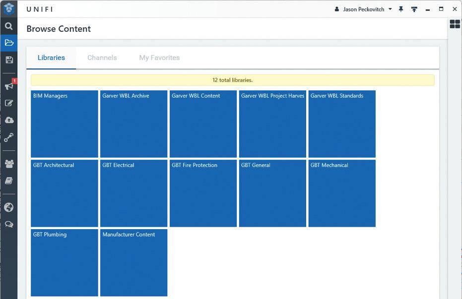
I would recommend a Content Management Solution for any firm that has Revit content they are maintaining. There are several options out there and it is up to you and your firm to decide which one works best for your needs. Family Browser, Hive, Avail and Unifi (now called Content Catalog) are the main ones I know about. I have used all of them but Avail so far. For quite a long time I used Family Browser from Philip Miller at Kiwi Codes and I even beta tested V4 for him. It works great when your content lives on a network drive and that is where you want that content to live. We are currently using Unifi 3.10. I have beta tested the new Content Catalog version of Unifi and there is a lot left to be desired with several key features from Unifi being omitted in the new version. I am pretty sure we will continue to use Unifi as long as we can. What drew me to Unifi in the first place was not having to maintain multiple versions of our Revit families because we used many different versions of Revit. I like to create content in the oldest version of Revit so that content updates can be used on most projects. Users having to see the upgrading dialogue each time they loaded content, while very minimal, was still a pain point for users. This forced me to have several versions of content just so they would not see the upgraded dialogue. Unifi eliminates that because your content is upgraded in the cloud and the appropriate version is loaded into your project without watching it get upgraded. Win-Win for everyone in my book. Another great feature of Unifi is the different libraries you can create (and control access to) as well as the built-in content request function which is currently missing from Content Catalog.
HONORABLE MENTIONS
While these may be the main tools in my current toolbox, there are plenty of others that I have used or are currently using in my day-to-day tasks, and I would like to mention a few of them here that you can look up and research for yourself. Those tools are Autodesk’s BIM Interoperability Tools, Iconic BIM – Guardian, JOTools – Transfer Single, Evolve Labs – Helix, ArchiCAD – IFC Exchange, DiRoots –ProSheets, and the Bluebeam Add-in.
CONCLUSION
To sum up, MEP professionals can improve their workflow by using Revit add-ins. These tools, such as Keynote Manager, CTC Software’s BIM Project Suite and BIM Manager Suite, offer various features that can reduce time and boost efficiency. Other tools like Scope Box Synchronizer, pyRevit, Arrowhead Assigner, and Preview Image Generator also have unique advantages. A Content Management Solution is also suggested for firms that need to manage their Revit content. By using the right mix of add-ins, MEP professionals can simplify their work and achieve more productivity. What Revit add-ins do you have in your toolbox?

Jason Peckovitch is an Autodesk Revit Certified Professional for Mechanical and Electrical Design located in SE Iowa. He is a BIM Manager for Garver’s Buildings Business Line, specifically MEPF. Garver has nearly 50 offices across the United States and more than 1200 employees. His CAD/BIM career spans over 25 years but he didn’t switch to the AEC Industry until 2007 as a Mechanical HVAC Drafter and transitioned into BIM Management shortly after where he has been working since. Jason is also the father of three children; Shelby – 12, Blake –9 and Logan - 6, a published photographer, gamer, and car/tech guy. He can be reached at jmpeckovitch@ garverusa.com.
Figure 11 - Unifi Libraries
BricsCAD® The Guide to Change Management

Picture this: a family with 3 children, the children come home from school, and immediately raid the pantry for snacks. No rules. Eat what you want. This went on for years. All of that was fine until the parents noticed the children were no longer hungry for dinner. It affected the entire house. That is until the parents unified and said, “No More Snacks after school” and implemented change. One child was happy as they didn’t really eat snacks anyway. The middle child just shrugged their shoulders. The third child said, “It’s not fair! You’re being the meanest parents ever!” and stormed out. While this story sounds ridiculous in this context, believe it or not, this is a typical parallel scenario in organizations and companies, and quite frankly, it’s human nature.
The parents (CEO/CFO) don’t like the direction things are headed within the family (Organization/ Company) and see the need for change. The children (End Users) enjoyed the fact that there are no rules. The CEO/CFO has communicated to the end-users; paraphrasing, “Things are going to change around here,”, and how did the children receive it?
One child was happy and accepted the change. One child was indifferent and seemed like they would be on board with it after a week or so. And the last child rebelled as if the parents were the worst parents on the planet. Are you starting to see the parallels?

Join Grant Dott and me as we discuss our daily experiences assisting clients transitioning to and implementing BricsCAD®. We’ll share common practices that can be applied by your organization to any scenario, with a particular focus on those implementing CAD software.
GETTING READY FOR THE SWITCH?
“Grant, can you give us some reasons why companies are looking to switch CAD products?”
“Sure thing, Craig. There are usually three reasons why companies and organizations are looking to change CAD products.”
“Saving money! Companies love saving money. And now more than ever, they are looking for additional ways to cut costs without having layoffs or reductions in force. Inquiring about an alternative software at a lower cost is a minimal risk/high reward venture.”
“Additional functionality. While CAD is a general term, no two CAD products are identical. A lower cost CAD product, like BricsCAD, may in fact have more intuitive functionality for the user, which increases productivity.”
“And lastly, organizations are simply unhappy with the current CAD solution. Some companies really dislike their current software and will do anything to move away from it. It might be anything from poor customer service, a change in licensing structure to diminished functionality and corporate greed.”
“Thanks, Grant.”
While these are the most common reasons that we encounter, there are still many more. Also, when it comes time to look at the switch, be sure to share your reasons and findings with your end users. Not surprisingly, this kind of information may not be shared with the end users until implementation is upon them. As well, management should also be included in the process. You wouldn’t leave the children with the babysitter and not update the babysitter with the new rules, would you?
IMPLEMENTING THE STEPS
Don’t wait until your current CAD contract is nearly out of date and secretly uninstall the user’s current CAD program and replace it with a new solution. While it is not our recommendation, we have seen it happen.
“Grant, tell us how well this type of switch is received by the users?”
“Craig, I can tell you that it is not well received at all. It is imperative to plan the switch. The users are upset by the lack of notice from management. They have customizations that cannot be migrated and other preferences that are just lost. In general, it causes chaos. So, communicate the change in advance. Our advice is to assemble a team that is responsible for planning, gathering, executing, testing, implementing, and gaining feedback from the other users. You may also want to consider this team in the decision-making process.”
“The Implementing Steps are where we gather the information needed to ensure a proper transition.”
“Craig, once the switch has been decided, it is now time to get moving. How can we best make use of these four steps and get started?”
PLAN
“Well Grant, let’s start with planning. First of all, you need to get a grip on the current CAD ecosystem that you are moving from. You need to know how users and stakeholders of all types will be involved and the roles they will play. Similar to the CAD ecosystem, get a handle on the file structure and customizations. Outputs and output hardware need to be considered and evaluated; network and shared pathing, how project files are stored, distributed, and consumed. Additional resources needing to be migrated potentially include but are not limited to .ARX, LISP routines, custom hatch patterns, toolbar customizations, tool palettes, and fonts. This is also a reminder that there may need to be a recompilation of LISP/ARX/VB and .NET or custom code that may require more resources. Be diligent in discovering as much as you can before you start.” (See Fig. 1)
Figure 1 – Plan
EXECUTE
“Next, we have execution. The aim here is to develop a new BricsCAD machine setup on its own, running two parallel CAD environments. It’s best to have redundancy as you most likely won’t get everything the first time. Install BricsCAD. Create a User Profile and configure the necessary pathing and folder structures that you will need. Another note, please do not use your current CAD software profile. Migrate over customizations and test them for compatibility. Edit and update them until they perform as expected in the new environment. Remember to keep the User Profile up to date with any changes. Continue the process of building the new BricsCAD ecosystem and take time to test, which is our next step.” (See Fig. 2)
CHECK AND TEST
“Checking and testing may seem obvious, but it is important to maintain as similar a working environment as possible between the two machines. Every phase of execution requires testing and perhaps multiple testing with different parameters or file types. Test the outputs on different peripherals and compare them to the incumbent CAD product. Keep the User Profile up to date as you make changes in configurations and test again until you are satisfied it is correct. Continue to do so until you are satisfied that the build you have can be deployed to all users.” (See Fig. 3)
MANAGING THE SWITCH?
“As we mentioned earlier, assemble a team to manage the switch, where all stakeholders are kept
up to date and involved in the process. You don’t want some big boss controlling all aspects of this. If you have good people working in your organization, then they will generally manage themselves, right? What the big boss can do is challenge the team to embrace the change positively.”
“Grant, this is a big step, changing CAD systems. How do you see a business moving through the switch when there may be a few team members who might be a bit distant when it comes to change, especially a big one such as this?”
“Craig, unfortunately, not all of us like change. And this is where the rest of the team can come to the rescue. Some changes require a learning process and supportive team members can help with the learning curve of others. By keeping in mind the four steps, as above, the process of migrating from A to B can be part of the learning curve. It is an opportunity to see how things react in a different environment and adapt to the situation. And let’s face it, switching to BricsCAD is not as difficult as it may seem at the start of the process. It is an environment with a similar look and feel and a low learning curve for seasoned Cadders.”
“Good point, Grant. Let’s also not overlook how important training is to the user. Regardless of how familiar the new software is, it is imperative to train and support your staff. While there may not be a huge difference in how things operate within the UI, creating familiarity and getting users on board is crucial. There might be a keystroke difference, here or there. For some, it’s no big deal, just like child number one. And for others, like child number three, it’s the end of the world. Additionally, BricsCAD offers a variety of machine-learning productivity tools that are not offered in other CAD programs, so this may also
Figure 2 – Execute
Figure 3 – Check and Test
mean that a revision in standards, procedures, and processes is potentially needed. But instead of throwing the baby out with the bath water, carefully consider what aspects are salvageable and worth preserving, while discarding those that are not serving you well.”
CONCLUSION
It’s human nature to resist change and new rules. Change can be scary. It can be frightening. However, implementing CAD software is none of those if you plan, execute, check, and test. You might even discover that this change had a positive effect on your organization. Lastly, once implementation is complete, grab your favorite snack from the pantry and enjoy your efforts. Of course, just not before dinner.
MORE ABOUT BRICSCAD®
Bricsys® BricsCAD® is professional CAD software without compromise. Accelerate your time to deliverable without compromising on performance, cost, licensing flexibility, and data security. Not ready to buy? Download the free, 30-day trial of BricsCAD® at Bricsys.com. Would you like free lessons? We have that available with Bricsys Learning. Ready to migrate to BricsCAD®? Download the Migration Guide. The latest version of BricsCAD® improves the tools and features users love, as well as new functionality and UI that supercharge productivity. Follow us today on LinkedIn and Youtube
MORE ABOUT BRICSYS®
Bricsys®, part of Hexagon®, is the global technology company that creates the BricsCAD® family of computer-aided design (CAD) products and the Bricsys® 24/7 project collaboration platform. We are relentlessly committed to the success of our customers by offering costeffective, mission-critical CAD software with industry-leading product support. Learn more at www.Bricsys.com.
Hexagon is a global leader in digital reality solutions. Learn more about Hexagon (Nasdaq Stockholm: HEXA B) at hexagon.com and follow us s@HexagonAB.

Mr. Craig Swearingen is a Global Implementation Specialist and Consultant at Bricsys. Currently, Craig provides migration and implementation guidance, management strategies, and technical assistance to companies which need an alternative, compatible CAD solution. Craig spent 19 years in the civil engineering world as a technician, Civil 3D & CAD power user, becoming a support-intensive CAD/IT manager in high-volume production environments. Craig is a longtime AUGI member (2009), a Certified Autodesk® AutoCAD® Professional, and he enjoys networking with other CAD users on social media.

Mr. Grant Dott is a Global Implementation Specialist and Consultant at Bricsys. He is a part of the EMEA Bricsys team based out of the UK. Grant has a strong client-facing background with the ability to adapt and focus across many disciplines and environments. Grant has a demonstrated history of working in the computer software industry, skilled in BricsCAD, AutoCAD, Production Management, Construction-based cloud technologies, and Software Development. Grant can be found on YouTube, promoting BricsCAD and demanding that you let him “show you how.”
by: Craig

BricsCAD® Design Solutions with IndustryLeading Applications
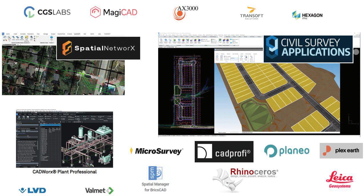
Here at Bricsys®, we pride ourselves in bringing you professional CAD software without compromise. Accelerating your time to deliverable without compromising on performance, cost, licensing flexibility, and data security. Not only is that a promise to our users, but also to the vast variety of industry-leading developers and third-party applications that use our highly compatible BricsCAD® BRX API. (See Fig. 1)
While there are hundreds of applications that run on BricsCAD, see the extensive list at https://bricsys. com/applications/, we want to showcase a couple of applications that have truly made their mark, continue to gain traction and demonstrate the diversity of how working with BricsCAD can assist with your design solutions.

MICROSURVEY SOFTWARE: INNOVATING SURVEYING SOLUTIONS
MicroSurvey Software Inc., a division of Hexagon, has been a prominent name in the surveying software industry since its inception in 1985. Headquartered in Kelowna, British Columbia, MicroSurvey is renowned for its robust, reliable, and innovative software solutions tailored for
land surveyors, civil engineers, construction professionals, and forensic reconstructionists.
COMPANY HISTORY AND MISSION
Founded to address the need for efficient and precise surveying tools, MicroSurvey has continuously evolved, integrating the latest technological advancements to enhance its software offerings. The company’s mission is to provide high-quality software that simplifies complex surveying tasks, ensuring accuracy and efficiency. This commitment to innovation and excellence drives MicroSurvey to support the professional growth of its users by offering intuitive and reliable products.
CORE VALUES
MicroSurvey’s core values reflect its dedication to its customers and the quality of its products. These values include:
• Innovation: Continuously pushing the boundaries of what’s possible in surveying software.
• Quality: Delivering reliable, accurate, and userfriendly products.
Fig. 1
• Customer Focus: Providing exceptional support and resources to ensure customer success.
• Integrity: Maintaining transparency and honesty in all business practices.
KEY PRODUCTS
MicroSurvey offers a range of software solutions designed to meet the diverse needs of surveying professionals. Among its flagship products are MicroSurvey CAD, SurveyTools™ for BricsCAD® , and STAR*NET.
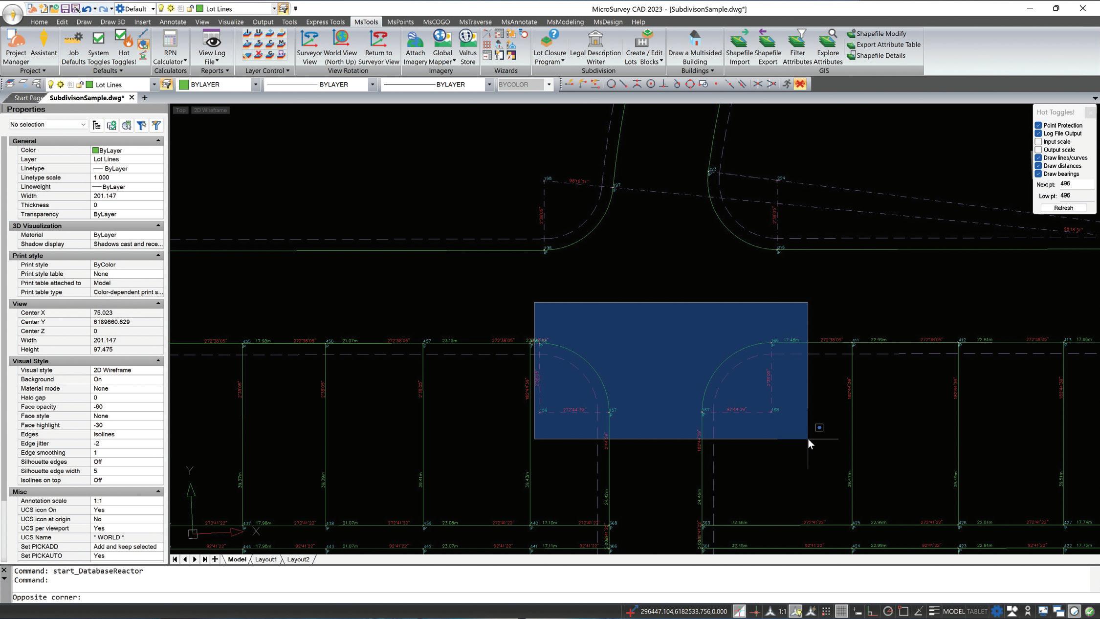
MicroSurvey CAD is a complete desktop surveying and design program created specifically for surveyors. (See Fig. 2) Unlike other CAD programs, MicroSurvey CAD is built from the ground up to cater to the precise needs of the surveying industry. It offers powerful tools for data collection, data editing, and design, including:
Advanced COGO (Coordinate Geometry): Facilitates precise calculations for various survey tasks.
• Surface Modeling: Enables the creation and analysis of detailed surface models for topographical surveys.
• Point Cloud Processing: Allows users to work with large datasets from LiDAR and photogrammetry.
• Integrated Data Collection: Seamlessly integrates with popular data collectors, streamlining the workflow from field to finish.
MicroSurvey CAD supports various formats and offers interoperability with other CAD programs, making it a versatile choice for surveyors looking to enhance their productivity and accuracy.
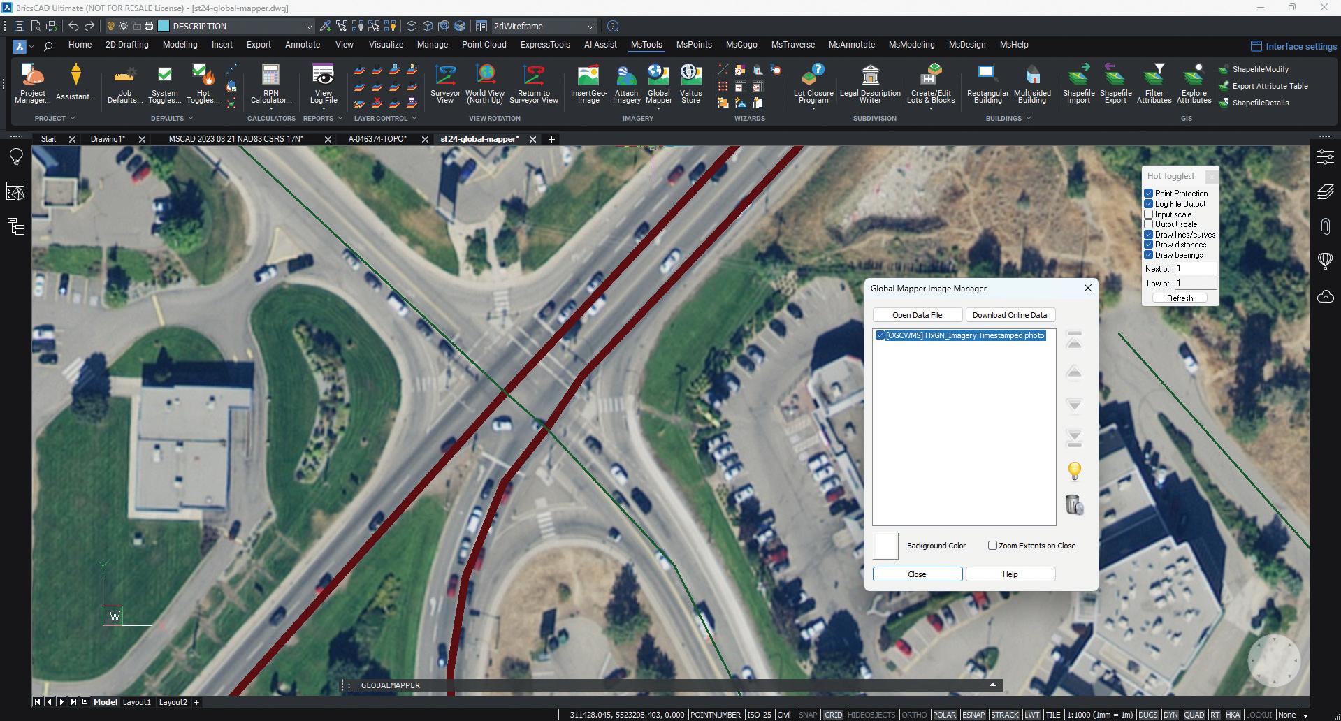
SurveyTools™ for BricsCAD® extends the functionality of the BricsCAD® platform by adding a suite of tools specifically designed for surveyors. (See Fig. 3) This addon leverages the powerful BricsCAD® engine to offer advanced surveying capabilities, including:
• Field-to-Finish Functionality: Automates the processing of field data to generate final deliverables quickly.
• Data Import and Export: Supports a wide range of file formats, ensuring compatibility with other surveying equipment and software.
• Customizable Workflows: Allows users to tailor the software to their specific project needs, enhancing efficiency and accuracy.
• Comprehensive Survey Tools: Provides tools for creating and managing points, lines, and surfaces, as well as for performing complex calculations.
By integrating with BricsCAD®, SurveyTools™ offers a cost-effective solution for surveyors who require advanced features without the high cost associated with other CAD programs.
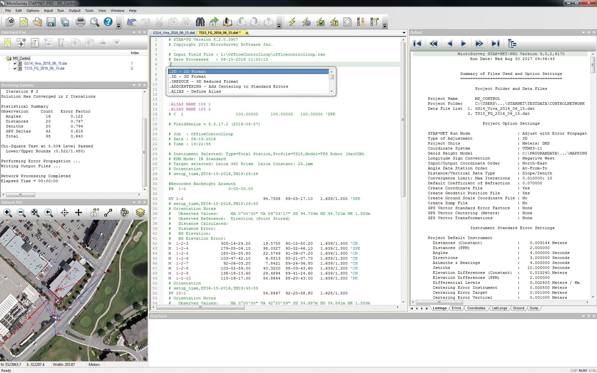
STAR*NET is renowned as the industry standard for least squares adjustment, a crucial technique for planning surveys and modeling the error and uncertainty in survey measurement networks. (See Fig. 4) STAR*NET is used by surveyors worldwide to:
• Adjust Observations: Corrects survey data using residuals to identify blunders and ensure reliable results.
• Combine Data from Multiple Sources: Integrates data from total stations, GPS, levels, and other instruments, providing a comprehensive adjustment solution.
• Error Detection and Correction: Identifies and corrects errors in survey data, ensuring compliance with accuracy standards.
• Flexible Reporting: Offers detailed and customizable reports to meet various project requirements.
STAR*NET’s ability to handle complex adjustments and its user-friendly interface makes it an indispensable tool for surveyors who need to ensure the highest level of accuracy in their work.
CONCLUSION
MicroSurvey Software Inc. stands out in the surveying industry due to its dedication to innovation, quality, and customer satisfaction. Its suite of products, including MicroSurvey CAD, SurveyTools™ for BricsCAD®, and STAR*NET, provides comprehensive solutions for the diverse needs of surveying professionals. By continually enhancing its software and supporting its users, MicroSurvey ensures that surveyors have the tools they need to succeed in an increasingly complex and demanding field.
For more information about MicroSurvey and its products, visit:
MicroSurvey Software at www.microsurvey.com

Fig. 3
4
SPATIALNETWORX: LEADING TELECOMMUNICATIONS GIS SOLUTIONS
SpatialNetworX is a global provider of telecommunications GIS physical network inventory software. Our mission is to offer the telecommunications community high-quality, comprehensive planning and design software solutions for fiber, coax, and copper networks, including integrated CAD from BricsCAD® and AutoCAD®. We promote diversity, equity, and inclusion across our global workforce spanning three continents.
COMPANY OVERVIEW
Founded in Australia in 1999, SpatialNetworX’s core application, spatialNET, was selected as a foundational OSS to design and operate the new Australian national wholesale open-access data network. This network currently serves more than 4.4 million customers and 9 million broadband services. Since its inception, SpatialNetworX has become the network planning and design software of choice for many of North America’s tier 1 and 2
telecommunications providers and has expanded its presence in the APAC region.
SpatialNetworX offers a suite of complementary products, each uniquely designed to help network operators efficiently plan, design, and operate their networks. These products also facilitate access to network data and integration with other OSS and BSS systems.
FOCUS PRODUCTS: SPATIALNET AND SPATIALINSIGHT AUTOMATED DESIGN
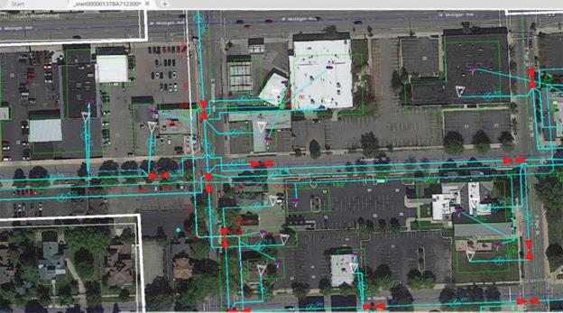
SpatialNET is SpatialNetworX’s core physical network inventory system, which seamlessly leverages BricsCAD® as its graphical engine. It allows network builders and operators to model and accurately display every aspect of their fiber, coax, or copper networks accurately. SpatialNET provides a single database for all network planning, design, operating processes, and reporting.
Some of SpatialNET’s core capabilities include:
• Modeling all passive and electronic equipment and inside plant electronics from origination/
Fig.
termination points to the optical wavelength level.
• Supporting all major transmission architectures (fiber, RF coax, and copper), including powering.
• Capturing aerial and underground infrastructure such as poles, cable supports, manholes, conduits, and direct-buried trenches. (See Fig. 5)
• Maintaining relationships between transmission and support networks, ensuring all connected elements are traceable.
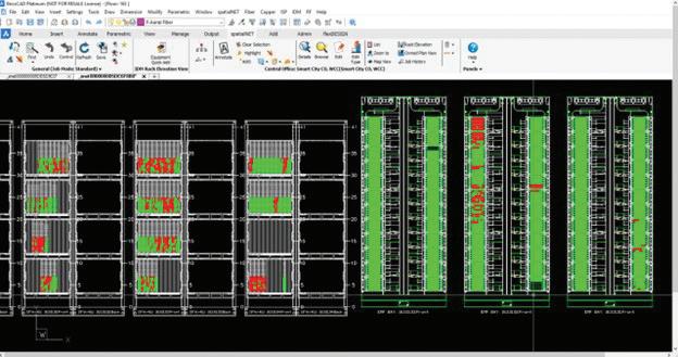
• Modeling common equipment types (e.g., nodes, splitters, splice cases) as they appear in the network. (See Fig. 6)
• Providing landbase tools to import or model streets, addresses, political, commercial, and service boundaries from scratch.
• Including specialized wizard tools for the design and drafting of each network type.
spatialINSIGHT - Automated Design is an industryleading set of tools that leverage open-source graph database technology for automated fiber design. It provides fast, full FTTH network designs or pointto-point designs according to the network owner’s specifications.
Some of the core SpatialINSIGHT capabilities include:
• Requires only street networks and address locations to produce FTTH designs instantly.
• Can import address and road data from multiple formats if not available in the core database.
• Supports real-world scenarios: brown or greenfield deployments; aerial, direct-buried, or conduit; using existing support networks or roads, distinguishing between urban, rural, and hybrid areas, optimizing costs accordingly.
• Allows designers to rapidly develop and evaluate alternate editable high-level designs, including costs and bills of materials.
• Automatically generates complete low-level designs in minutes, including:
• Drafting and auto-naming support elements such as poles, pedestals, handholes, and their associated linear strand, trench, and conduit.
• Placing and auto-naming cabinetized equipment with upstream and downstream connections.
Fig. 5
• Drafting and naming all fiber cables according to offset rules and connecting all circuits.
• Generating complete, costed bills of materials.
• Generating network statistics such as PON string utilization, split ratios, min/max distances, and signal loss.
• Creating detailed A-Z network schematics
• Creating KML exports for sharing designs (See Fig. 7)
• Exports both low and high-level designs to KML or other formats like ESRI SHP for review and approval.
• Upon approval, integrated BricsCAD® or AutoCAD® can be used to produce detailed work print construction drawings. These drawings contain all the measured and detailed information required for network construction, including site plans, equipment layouts, splice details, and additional specifications and notes required by construction personnel.
• Includes a point-to-point design tool for generating various path options, such as extending to a new customer site. It can
generate the shortest path based on existing networks or roads and optimize paths for additional commercial opportunities between any two points.
CONCLUSION
CAD is ubiquitous in telecommunications for creating work print construction drawings, permit drawings, and other visual documents necessary for the construction and maintenance of communication networks. Using non-CADbased applications to model networks requires transitioning between multiple systems. SpatialNET and spatialINSIGHT products demonstrate the power and flexibility of seamlessly integrating bestin-class commercials like BricsCAD® in advanced fiber planning and design applications.
For more information about SpatialNetworx and its products, visit:
SpatialNetworx at https://spatialnetworx.ai/
MORE ABOUT BRICSCAD®
Bricsys® BricsCAD® is professional CAD software without compromise. Accelerate your time to deliverable without compromising on performance,
Fig. 6

7
cost, licensing flexibility, and data security. Not ready to buy? Download the free, 30-day trial of BricsCAD® at Bricsys.com. Would you like free lessons? We have that available with Bricsys Learning. Ready to migrate to BricsCAD®?
Download the Migration Guide. The latest version of BricsCAD® improves the tools and features users love, as well as new functionality and UI that supercharge productivity. Follow us today on LinkedIn and YouTube.
MORE ABOUT BRICSYS®
Bricsys®, part of Hexagon®, is the global technology company that creates the BricsCAD® family of computer-aided design (CAD) products and the Bricsys® 24/7 project collaboration platform. We are relentlessly committed to the success of our customers by offering cost-effective, missioncritical CAD software with industry-leading product support. Learn more at www.Bricsys.com.
Hexagon is a global leader in digital reality solutions. Learn more about Hexagon (Nasdaq Stockholm: HEXA B) at hexagon.com and follow us @HexagonAB.

Mr. Craig Swearingen is a Global Implementation Specialist and Consultant at Bricsys. Currently, Craig provides migration and implementation guidance, management strategies, and technical assistance to companies which need an alternative, compatible CAD solution. Craig spent 19 years in the civil engineering world as a technician, Civil 3D & CAD power user, becoming a support-intensive CAD/IT manager in high-volume production environments. Craig is a longtime AUGI member (2009), a Certified Autodesk® AutoCAD® Professional, and he enjoys networking with other CAD users on social media.
Fig.
Different Teams, Same Project: Collaboration in AEC Design
Projects in the AEC industry are more than one person, more than one team, and more than one solution. One thing is for sure: when deep in design and trying to meet deadlines, we get tunnel vision and only see our own requirements, to meet our own deliverables and deadlines. This is not the mindset in the beginning days of a project. When we get together to discuss a project, lay out the desired elements, and set deadlines, the project is discussed as a team. As the project progresses and deadlines arrive, the stress of meeting those requirements increases. Everyone retreats back to their silo to finalize details and ensure they finish on time.
Team meetings still happen frequently, but the atmosphere changes from the once passionate creative discussions of pre-design to teams working to meet last-minute changes that must be incorporated before delivery and many other expected issues that always arise. Certain things are assumed as time goes on. We know that a large mechanical duct needs to be addressed by architecture, and confirmation that nothing clashes with a structural element is a priority. Three disciplines requiring confirmation to ensure one element isn’t interfering or causing conflict elsewhere in a project are essential to the design process.
REACHING YOUR FIRST DELIVERABLE. ON TIME?
Your first deliverable is fast approaching, and you have just three weeks until you must submit your initial set of sheets. Suddenly, news hits: the
client has been informed that they cannot bring in services from the originally planned side of the town, necessitating entry from the opposite side of the property. Compounding the issue, you are informed that the mechanical equipment initially selected will not support the proposed number of residences for the apartment unit, requiring alterations to accommodate new equipment.
These changes create significant challenges, as the service rooms and access points must be moved and completely redesigned. While you are not responsible for the full redesign until the next submission, you must still present a preliminary layout and make as many accommodations as possible. Additionally, you need to finalize your sheets and ensure they are ready for submission.
Numerous instances like these can cause delays and jeopardize meeting deadlines. To navigate these hurdles, it is crucial to stay connected with your team and consultants, ensuring that all information and changes are clearly communicated. This allows all disciplines to make the necessary adjustments promptly, reducing the risk of errors and delays.
By maintaining clear and continuous communication, fostering a collaborative environment, and utilizing real-time updates through collaborative tools, you can effectively manage these challenges. This approach helps meet deadlines and ensures the quality and accuracy of the project deliverables.
Autodesk
WHEN SHOULD WE WORRY ABOUT MODEL CLASHING?
When do you begin model clashing?
Everyone who reads this will have a different answer. Whether you start it midway through or before tender, projects across the industries start clashing at various stages. Dare I say, some projects never truly clash, but do it manually in the models. Maybe you’re new to this and looking for insight into what to do. We all have different answers to this question.
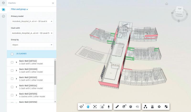
Model clashing is essential for successful designs and reducing stress during deadlines. While considering clashing from the project’s inception might seem daunting, solutions like ACC make it manageable. By setting up Model Coordination
with the models turned over to design teams early on, the process becomes easier to manage. This proactive approach enables live clashing, streamlining the design process and minimizing last-minute issues.
Situations like these reinforced the importance of establishing a BIM Services Team and equipping them with the tools to support design teams in delivering projects efficiently and effectively. Having experts available to assist designers ensures that content and standards are met, while also addressing issues related to templates and formatting.
COORDINATION MEETINGS
Coordination meetings serve as a crucial forum for teams to come together and discuss various aspects of the project. These meetings provide an opportunity to identify potential clashes, seek clarification on design elements, and address any concerns that may arise.
Typically, these meetings are facilitated by a Project Coordinator who guides the discussion through each discipline’s contributions. They inquire about progress, potential obstacles, and whether deadlines are likely to be met. Encouraging open communication, teams are urged to voice any challenges or issues they may encounter.
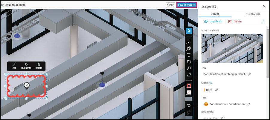
To enhance the effectiveness of coordination meetings, consider incorporating a clash review
Autodesk Construction Cloud

[photo credit: www.freepik.com]
process. By utilizing programs and solutions that support an active clash detection system, potential obstructions can be identified early in the design phase, minimizing the need for extensive redesigns later on. This proactive approach not only streamlines the coordination process but also helps ensure smoother project progress and timely delivery.
MARK-UPS AND REVIEWS
Let’s start with the fact that no one particularly enjoys this part of the project. We know it has to happen; we just hope for minimal mark-ups and no major changes. Regardless, submitting your design to your discipline lead for review is an essential step in the process. This phase can be daunting, but it’s also an opportunity for growth
and improvement. Receiving feedback helps ensure that the design meets all necessary standards and client expectations.
Effective mark-ups and reviews can significantly improve the quality of the final deliverable. Constructive feedback allows for the identification and resolution of potential issues before they become critical. This process is vital for maintaining the project’s integrity and achieving a successful outcome.
To make the review process smoother, it’s beneficial to use collaborative tools that allow real-time markups and comments. This approach not only speeds up the review process but also ensures that all team members are on the same page. By embracing this collaborative mindset, you can turn what is often seen as a tedious task into a valuable part of the project workflow.
Remember, the goal of mark-ups and reviews is not just to point out flaws but to enhance the overall design. Approach this phase with a positive attitude and use it as a chance to learn and improve. Clear communication and an open mind can turn feedback into a powerful tool for success.
BIM SERVICES - DESIGN MANAGEMENT AND PRODUCTION IS OUR EXPERTISE
A successful BIM Services Team must include a diverse group of professionals from across the industry, each possessing exemplary skills that benefit
[photo credit: Autodesk]
various sectors and design teams. Our team supports your AEC IT needs, project setup and management, design coordination, content and data management, and package assembly. We are relied upon for our expertise and unwavering support.
The ability to navigate various software, disciplines, and coordinate among teams is crucial for a BIM Services Team. This team should be composed of professionals with a wide range of expertise. Not every member needs to have all the skills necessary for every task; instead, having specialists in key areas significantly reduces the time spent fixing problems, managing standards and templates, and collaborating with designers.
By bringing together experts in major areas, a BIM Services Team can streamline processes, enhance efficiency, and ensure that projects are delivered to the highest standards. This specialized support not only aids in maintaining project quality but also fosters a more cohesive and effective working environment, ultimately leading to successful project outcomes.
DRIVING PROJECT SUCCESS WITH PROACTIVE STRATEGIES
In the fast-paced world of AEC design, successful project outcomes rely heavily on effective communication, collaboration, and coordination among diverse teams. From the inception of a project to its final deliverables, these elements serve as the bedrock of project success, ensuring that goals are met, deadlines are achieved, and quality is maintained.
Throughout our careers, we’ve witnessed the critical role that communication, collaboration, and coordination play in navigating the complexities of AEC projects. While challenges may arise, particularly as deadlines loom and requirements evolve, proactive strategies can mitigate risks and keep projects on track.
Coordination meetings serve as a vital platform for teams to come together, identify potential clashes, and address challenges head-on. These meetings, facilitated by Project Coordinators, provide a forum for open communication and problem-solving, fostering a collaborative environment where ideas can flourish, and issues can be resolved.
Additionally, the incorporation of clash review processes into coordination meetings can further
Autodesk Construction
enhance their effectiveness, enabling teams to identify and address issues early in the design phase. By leveraging technology and collaborative tools, teams can streamline workflows, minimize errors, and ensure smoother project progress.
Though often perceived as tedious, mark-ups and reviews present valuable opportunities for growth and improvement. By embracing feedback and utilizing collaborative tools for real-time mark-ups and comments, teams can enhance the quality of their designs and ensure alignment with client expectations.
Furthermore, the establishment of a dedicated BIM Services Team, equipped with diverse expertise and specialized support, can significantly bolster project efficiency and effectiveness. By harnessing the skills of these professionals and leveraging their knowledge, teams can navigate complex challenges and deliver projects to the highest standards.
As we continue to drive project success with proactive strategies, let us remain committed to fostering a culture of communication, collaboration, and coordination. By embracing these principles and taking concrete steps to enhance them, we can achieve greater efficiency, innovation, and success in our AEC projects.
Remember, the success of companies and projects hinges on these three key elements: communication, collaboration, and coordination. Let’s continue to prioritize these principles and build a brighter future for the AEC industry together.

Kristina Youngblut is a seasoned professional with more than 20 years of expertise in CAD solutions and technology within the AEC community. A BIM Professional determined to deliver innovative solutions and cutting-edge technologies to projects and clients. Kristina also serves on the AUGI Board of Directors since 2023. As an esteemed member of the Autodesk Expert Elite program, she passionately contributes to the sharing and exploration of knowledge within the industry.
More Revit Add-Ins that live on my screen!
Greetings again, Gentle Readers! Today I’d like to introduce you to more old friends who have been living in my Revit UI for a long, long time.
Here are some more helpful - and possibly, not quite so helpful - friends from my Desktop that I’d like you to meet!
But before that, as always, let’s get the formal introductions out of the way -
Gentle Reader - More Add-Ins on Rina’s Desktop
More Add-Ins on Rina’s Desktop - Gentle Reader
Which add-ins might those be? Let’s take a look at
• CTC Tools for Revit
CTC Productivity
CTC TOOLS -
• CTC Management
• Imaginit Utilities
An interesting feature of CTC tools is that each segment has a set of helpful Free Tools just to pique your interest! Tools provided with light background colors are free tools that run without any special licensing. The tools with dark background colors are premium tools which require licensing.
Here’s something annoying that I noticed - unless preconfigured by the system admin, this dialog box will appear the first time any of the licensed tools are
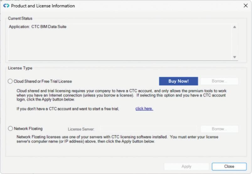
launched. This requires specifying the kind of license that is to be used. Even though, Gentle Reader, I am NOT amused, the prospect of keeping the IT guys on their toes is vaguely entertaining at best!
CTC MANAGEMENT - CTC BIM MANAGER SUITE

My favorites out of their Free Tools
Family Preview Manager - Would you believe it!
Add multiple files and go into Options to fine tune the graphics of the Preview Image.
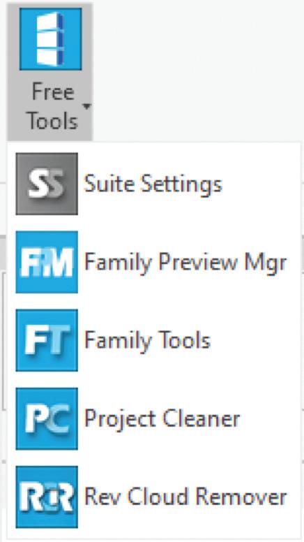
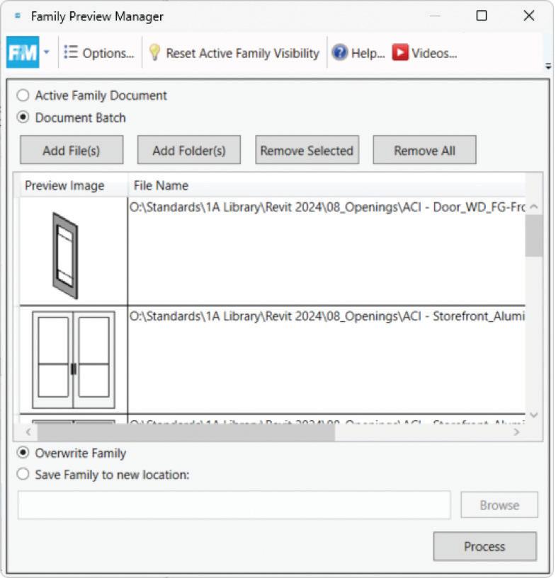

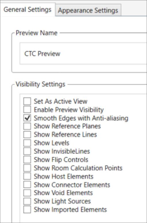
It’s the Appearance Settings Tab that I really like! Take a look – now you can control the preview angle, Display Style, and Detail Level of the preview. I’m sure you’ll agree that just this capability deserves its own supersized graphic!
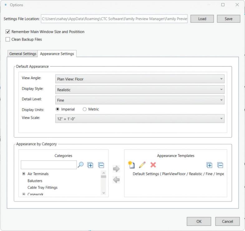
Once this is done, you can save the enhanced Preview to the Family in your library
Something to remember – this worked best for me on families that were saved to my hard drive, it did not seem to recognize the paths of families saved to the network. Hopefully I’m just imagining things and one of my Gentle Readers can (gently, I hope) point out to me the error of my ways.
All things said and done; this is a truly nifty tool that goes quite a way to address the angst of the Backwards Family Preview expressed by most Revit aficionados. It will not add flowers, people, maybe even the family Labrador to the preview – but you know, Gentle Reader – I’m not complaining!
PROJECT CLEANER
Here’s another contender for the title of Model Health Protector champ! Open this tool while in the Project environment, and this is what you will see –
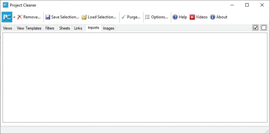

This goes beyond the capabilities of Purge Unused by giving you a one stop shop to view and remove unused Views, View Templates, Filters, Sheets, Links, Imports, and Images.
Another similar tool that I have developed very strong feelings for – the Import and Link Manager.
This is a one stop shop to see What has been Linked / Imported, Which views / sheets the instances live in (and which would be affected by their removal), File Type, Whether Room Bounding / Pinned or not, Linked file location, Path type, File size.
CTC
PRODUCTIVITY
- CTC BIM BATCH SUITE
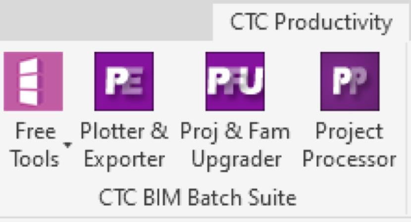
Before we look at some of the Free Tools in this group, let’s look at the Proj & Fam Upgrader-
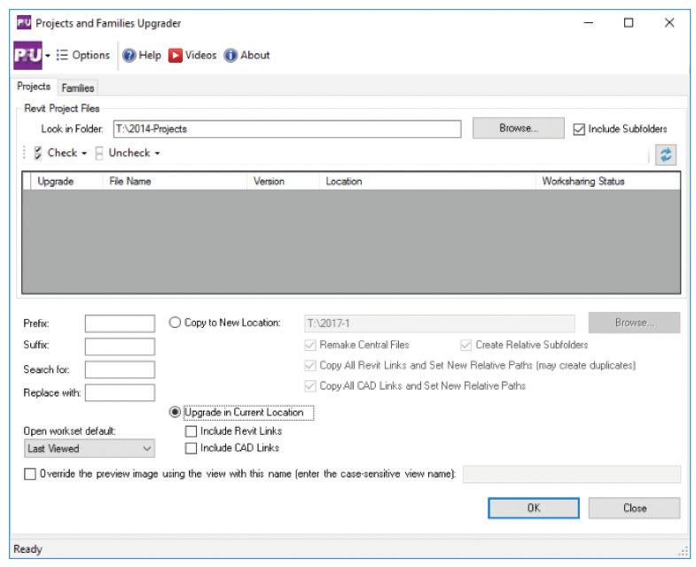
This tool can be helpful when upgrading your libraries at the time of switching your team over to a new version of Revit.
Now for the Free Tools –
FAMILY EXPORTER
This tool allows you to selectively export families out of Revit. You can export Families as a group or individually by their Geometry or their Category.
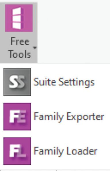
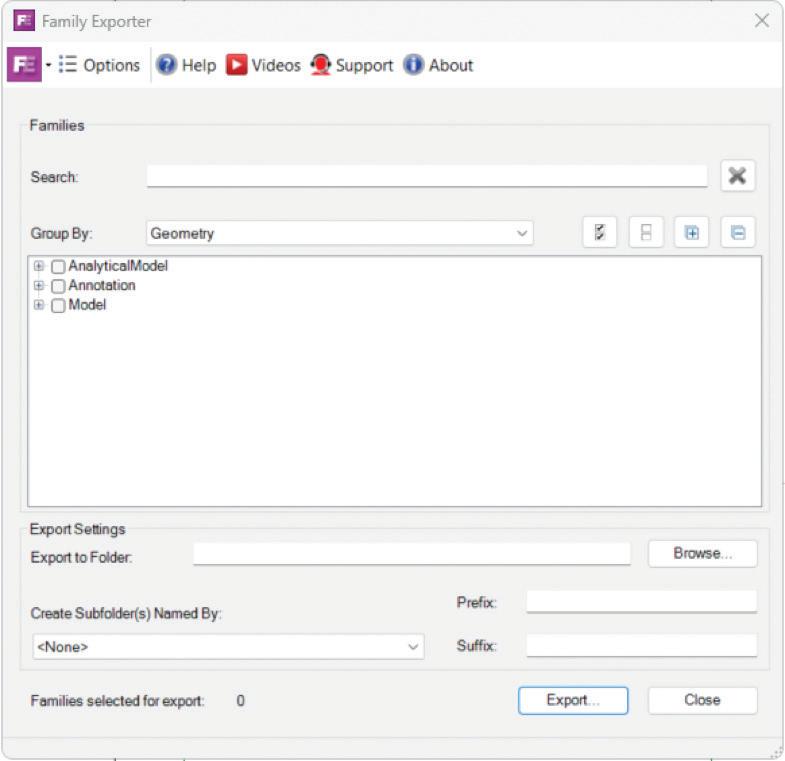
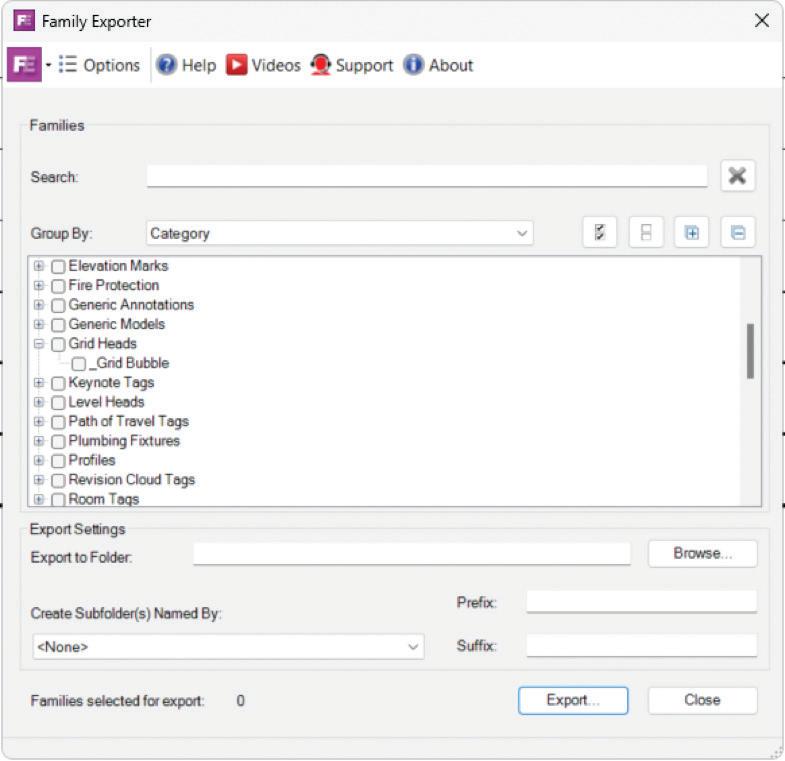

Let’s look at the Free Tools here -

Quick Select
This tool definitely deserves mention here –
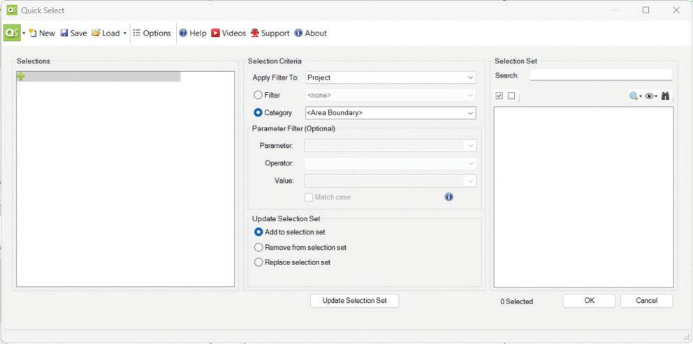
It plays nicely with Selection Sets, allowing you to edit or replace existing Selection Sets
Noteworthy among its superpowers is that it allows you to use Revit Filters to select elements OR you can select by Categories.
Inside Track
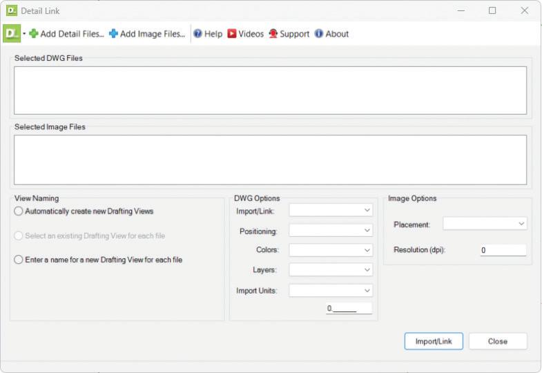
Detail Link - Assists with linking DWG standard details, probably from a legacy details’ library. It does the same with image files.
View Aligner
A helpful tool to make your sheets look nice. In addition to the ability to align Views by
Edge (Top, Bottom, Left, Right)
Horizontal / vertical Centerline
You can also align Views by
Level
Grid intersections
Grid and Level intersections

ImaginIt Utilities
One of the perks of having ImaginIT as a reseller is this nifty toolbox that you can avail yourself of at no additional charge (to the best of my knowledge).
Some of my favorites –
Renumber – renumbers selected elements in the order that you select them. Very helpful when renaming Rooms, or if you’ve crammed a gazillion views in a sheet and need to renumber them.
Journal Reader – quickly summons the relevant Journal for troubleshooting.
Place Family / Family Placement – when mapped to the server location of your libraries, will summon a palette with a visual representation of Library folders and families.
DWG Check – quick, targeted location and deletion of DWG imports.
A final word to the wise - as tempting as it may be to see your UI bedecked with these wonderful add-ins, please restrain the urge, O Gentle Reader. You will be giving Revit much too much to do, spraining its teensy-weensy little brain, which can lead to undesirable aftereffects like poor performance, possibly model corruption. Unleash them with discretion ONLY on an as-needed basis. Disable the Add-in once the need has passed. Better safe than sorry!
Watch out for the next episode, Gentle Reader! Until then - Keep Reviting!
Please let us know if you have some news to share with us for future issues. Likewise, if you are a featured product or news item user and would like to write a review, we want to know. Drop me a line at: rinasahay@gmail.com. We’d love to hear from you!





Bright Ideas for a Bright Future

AUGIWORLD brings you the latest tips & tricks, tutorials, and other technical information to keep you on the leading edge of a bright future.
