


Drivers to enabling economywide deployment of carbon management technologies
Page 20


Plus
The need to apply circular economy principles to accelerate CO2 storage
Page 16
AND
A case study examining how industrial collaboration can decarbonize the Midwest region
Page 24


feed services
Engineering
procurement
FACILITY & PIPELINE
CONSTRUCTION

direct air capture | air separation
carbon capture & sequestration

CONTACT SAULSBURY TODAY


Brix, OCOchem
Markley
Jeff Simmons and Ardian Nurfalaq, Toshiba America
Pennsylvania accelerated industrial decarbonization projects utilizing game-changing, low-cost cross-sector technology to generate clean energy jobs and sustainable products in hard-to-abate sectors, while preserving industrial manufacturing jobs
The


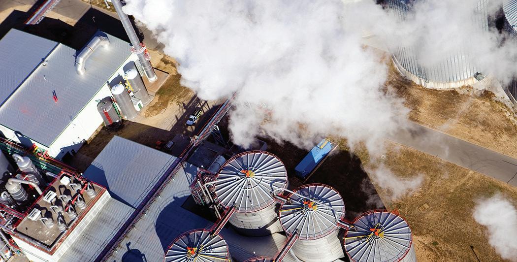
Carbon dioxide (CO2) is not merely an industrial byproduct; it is a vital component of Earth's natural carbon cycle and the most significant greenhouse gas, holding the key to transformative possibilities in our environment. However, human activities disrupt this balance, underscoring the urgent need to rethink our relationship with CO2 and embrace its potential in a sustainable circular economy.
In the page 5 column, "From Photosynthesis to CO2 Electrolysis", Todd Brix, CEO and Co-Founder of OCOchem, highlights CO2's crucial role. He explores how CO2 transcends its greenhouse gas label by participating in the biological carbon cycle and inspiring technologies like CO2 electrolysis. By converting CO2 into valuable products, we can mitigate emissions and advance a sustainable circular economy that redefines waste as a resource. These insights set the stage for understanding the broader implications of carbon management.
Building on Brix’s insights, our Business Briefs section on page 6 showcases advancements in carbon management. The Department of Energy's support for the Wabash Valley Resources project marks a monumental step toward low-carbon ammonia production, while Mission Zero Technologies’ modular direct air capture system exemplifies scalable solutions that align with Brix’s principles. Highlighting investments in carbon capture studies across the U.S. reinforces a collective commitment to effective carbon utilization.
Next, on page 12, Bruce L. Bruso, President and Chief Technology Officer at CBA Environmental, discusses pioneering CCUS technologies in Pennsylvania that reduce carbon footprints and create clean energy jobs. This illustrates how transitioning to a circular economy can drive economic growth, emphasizing the importance of job creation in this sector. Stewart Maxwell’s story on page 16 addresses the urgent need for effective CO2 storage solutions, advocating for innovative strategies that ensure captured CO2 can be safely stored or repurposed.
Leo Duke and Diana Leane emphasize on page 20 that support from political, business, and environmental sectors underscore the consensus on the necessity of carbon management. Legislation like the Inflation Reduction Act and Bipartisan Infrastructure Law has catalyzed significant investment in CCUS projects, establishing a foundation for commercialization.
Finally, on page 24, Marcos Miranda explores collaborations with the ethanol sector, showing how partnerships can accelerate CCS network development. He demonstrates that proximity to ethanol facilities can enhance CO2 capture and transport, reinforcing the interconnectedness of our carbon management efforts.
As we progress, it is vital to recognize that while advancements are being made, the journey toward a sustainable, net-zero future requires ongoing commitment and innovation across all sectors. Together, these insights reflect the momentum in carbon management and the collaborative efforts essential to realizing the full potential of a circular economy.
DANIELLE PIEKARSKI
CONTENT
MANAGER
Carbon Capture Magazine dpiekarski@bbiinternational.com
VOLUME 3 ISSUE 2
THE TEAM
CEO Joe Bryan jbryan@bbiinternational.com
President Tom Bryan tbryan@bbiinternational.com
Vice President of Operations, Marketing & Sales John Nelson jnelson@bbiinternational.com
Vice President of Production & Design Jaci Satterlund jsatterlund@bbiinternational.com
Senior Account Manager Chip Shereck cshereck@bbiinternational.com
Account Manager Bob Brown bbrown@bbiinternational.com
Content Manager Danielle Piekarski dpiekarski@bbiinternational.com
Circulation Manager Jessica Tiller jtiller@bbiinternational.com
Advertising & Marketing Manager Marla DeFoe mdefoe@bbiinternational.com
Subscriptions Subscriptions to Carbon Capture Magazine are free of charge to everyone with the exception of a shipping and handling charge for any country outside the United States. To subscribe, visit CarbonCaptureMagazine. com or you can send your mailing address and payment (checks made out to BBI International) to: Carbon Capture Magazine/Subscriptions, 308 Second Ave. N., Suite 304, Grand Forks, ND 58203. Reprints and Back Issues Select back issues are available for $3.95 each, plus shipping. Article reprints are also available for a fee. For more information, contact us at 866-746-8385 or service@bbiinternational.com.
Advertising Carbon Capture Magazine provides a specific topic delivered to a highly targeted audience. We are committed to editorial excellence and high-quality print production. To find out more about Carbon Capture Magazine advertising opportunities, please contact us at 866-746-8385 or service@bbiinternational.com.
Letters to the Editor We welcome letters to the editor. If you write us, please include your name, address and phone number. Letters may be edited for clarity and/or space. Send to Carbon Capture Magazine/Letters, 308 Second Ave. N., Suite 304, Grand Forks, ND 58203 or email to dpiekarski@bbiinternational.com.
COPYRIGHT © 2024 by BBI International
TM Please recycle this magazine and remove inserts or samples before recycling
By Todd Brix CEO and Co-Founder OCOchem
We hear a lot about CO2, but how much do we know about its importance to life on this planet? CO2 isn’t just a molecule, a by-product, or a greenhouse gas; it’s the essential molecule vehicle for moving carbon around in its depleted state. It’s part of a regenerative cycle, a fundamental aspect of our planet's energy and material balance—various ecological and geological systems cycle carbon dioxide through natural processes. It’s latent potential, the future form of life, and a valuable molecule for most things we consume and use on Earth.
One of the most crucial carbon cycles is the biological cycle. In this cycle plants, using a bio-catalyzed process known as photosynthesis, converts CO2 from the air, water and sunlight energy into more complex energized carbon molecules that we observe in the familiar form of plant leaves, stalks, flowers and fruits. When this “biomass” is consumed (i.e. eaten, burned, or decomposed), chemical bonds are broken, energy is released, and the carbon is oxidized, leaving CO2 released into the air. This process repeats endlessly, forming a continuous loop and powered by sunlight. Understanding the presence of CO2 in the world is just the beginning of a much bigger story.
Understanding the carbon regeneration process is the first step in realizing its economic and technological viability. Unlike photosynthesis, which relies on sunlight and biological catalysts to convert CO2 into organic compounds, we now have technology that does WHAT photosynthesis does, but not HOW it does it. We can apply a more robust, reliable and concentrated energy source (clean electricity) and a different catalyst to transform and regenerate CO2 and water, creating a reaction where carbon atoms are combined with hydrogen obtained from water (releasing oxygen) to produce essential organic (i.e. carbon-based) molecules and their precursors. This process, known as CO2 electrolysis, is distinct from photosynthesis and offers a promising alternative to accelerate decarbonization. By converting CO2 into products using clean electricity, we reduce CO2 emissions in two ways: first and most simply by the amount of CO2 that is regenerated, but the second way is less obvious but even more consequential by avoiding the CO2 emissions otherwise generated by making these same products from fossil fuels. This is known as carbon displacement or abatement.
For example, if you capture one ton of CO2 from the air or a flue gas stack and bury it, you’ve removed one ton of CO2 from the atmosphere. If, however, you convert that one ton of captured CO2 to make one ton of product that is otherwise made from fossil fuels, which emits seven tons of CO2, you’ve avoided seven tons of CO2 emissions, not just one ton. Converting, rather than burying CO2, reduces CO2 emissions by seven times as much. Converting CO2 into valuable products enables you to sell them and generate revenue, offsets carbon capture costs, and is seven times more impactful than burying CO2. Such an approach is more economically sustainable and seven times more environmentally impactful. This is the way.
CO2 electrolysis holds promise for reducing atmospheric CO2 levels and providing a sustainable method for producing chemicals, materials, and fuels. Its efficiency and scalability are active areas of research, but now, it is also commercialized, aiming to make it a viable commercial technology for both carbon management and molecule production.
As humankind has become part of a continuous cycle of carbon regeneration, it is clear that we are part of the circular carbon economy and now have an opportunity, using nature as a model, to evolve this process by reusing, not wasting, carbon for the betterment of everyone. Understanding and nurturing these natural processes is essential for maintaining atmospheric CO2 balance and ensuring a stable climate. Nature provides us with powerful tools; it's our responsibility to use them wisely and sustainably to balance our disrupted carbon systems and live in harmony with the natural systems that define how we live on this planet. Use, don’t waste, CO2.
The Department of Energy's (DOE) Loan Programs Office has committed $1.559 billion toward Wabash Valley Resources' (WVR) $2.4 billion low-carbon ammonia production project. This initiative aims to boost domestic fertilizer production, reduce reliance on imports and support the Eastern Corn Belt's agricultural sector. By using industrial waste and carbon capture, WVR could pioneer the U.S.'s first carbon-negative ammonia process, benefiting farmers by enabling the production of low-carbon corn and ethanol. The project is expected to create over 1,100 direct and indirect jobs, including 500 union construction jobs. Key partners like Baker Hughes, Honeywell, and Samsung E&A America are supporting the venture, which promises both environmental and economic benefits.
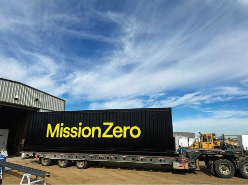
Mission Zero Technologies (MZT) has installed its third modular direct air capture (DAC) system at Deep Sky Labs in Innisfail, Alberta, Canada, marking the company’s first international deployment. Powered by solar energy, the system can capture up to 250 tons of carbon dioxide (CO2) annually for permanent underground storage. Deep Sky aims to eventually remove 100,000 to one million tons of CO2 each year as the project scales up. MZT's modular approach, using mature technologies and local supply chains, allows for rapid scalability and cost efficiency. This installation also provides crucial operational data from diverse climates, helping optimize DAC technology and secure future investment.
The U.S. Department of Energy (DOE) has awarded Navajo Transitional Energy Company (NTEC) $6.55 million for a Front End Engineering Design (FEED) study to assess adding carbon capture and storage (CCS) technology to the Four Corners Power Plant. The project could remove over 95% of the plant’s carbon dioxide (CO2) emissions, preserving more than 600 jobs and maintaining $183 million in annual economic impact for the Navajo Nation. The study, to be completed by 2025, will evaluate the feasibility of using amine-based carbon capture to extend the plant’s life beyond 2031. If viable, this would reduce emissions while securing the region’s power grid. The initiative aligns with federal efforts to advance CCS technology and attract private sector investment.


Milestone Carbon's Class VI carbon dioxide (CO2) injection well permit application for a carbon hub in the Delaware Basin of West Texas has been deemed administratively complete by the EPA. This carbon hub is designed for the permanent geologic storage of CO2, with each of the two wells capable of storing up to one million metric tons annually, and potential expansion to four wells. A Monitoring, Reporting, and Verification (MRV) Plan has also been filed. A final decision on the permit is expected in September 2026. Milestone Carbon’s hub, which covers over 30,000 acres, will support industries like natural gas processing and electricity generation in their decarbonization efforts. This progress highlights Milestone Carbon’s commitment to providing critical carbon sequestration infrastructure for industrial emitters.
1PointFive, a subsidiary of Occidental, has secured up to $500 million in funding from the U.S. Department of Energy’s Office of Clean Energy Demonstrations to develop the South Texas Direct Air Capture (DAC) Hub. The project aims to capture 500,000 metric tons of carbon dioxide (CO2) annually, with future expansion potential to over 1 million metric tons per year. Located on King Ranch in Texas, the hub could eventually remove up to 30 million metric tons of CO2 per year and store up to 3 billion metric tons in saline formations. The initial $50 million will fund engineering, permitting, equipment procurement, and community engagement. 1PointFive is also advancing local workforce development and educational initiatives as part of its Community Benefits Plan.


ExxonMobil has secured the largest U.S. offshore carbon dioxide (CO2) storage lease, covering over 271,000 acres in the Gulf of Mexico, from the Texas General Land Office (GLO). This offshore site complements ExxonMobil's onshore CO2 storage efforts, reinforcing the U.S. Gulf Coast as a leader in carbon capture and storage (CCS). The lease will support substantial emissions reductions by integrating CO2 capture, transportation, and storage solutions. The agreement will also benefit the Texas Permanent School Fund, contributing to education while promoting community development. ExxonMobil’s extensive pipeline network and infrastructure position it to lead in achieving net-zero goals through large-scale CCS.


Nationally there are 81 projects under regulatory review with a total of 246 wells. These projects and wells were located by owners and operators to make use of valuable pore space for long-term storage and to locate near large-scale emissions sources. As a result, projects are not evenly distributed across the United States; and this has focused attention on Class VI project interference.
Class VI projects are regulated under the Safe Drinking Water Act which is designed to protect underground sources of drinking water (USDWs). There are two mechanisms by which USDWs can be endangered by Class VI operations. The first is the upward migration of buoyant supercritical carbon dioxide into an overlying USDW. This upward migration could occur through improperly plugged artificial penetrations or flaws in the cap rock. The introduction of carbon dioxide into USDWs could result in changes in aquifer pH, precipitation or dissolution of solid mineral phases in USDW, and changes in the geochemistry which could mobilize naturally occurring contaminants, such as arsenic. The second mechanism is the upward migration of formation fluids induced by pressurization of the reservoir during injection. Formation fluids could migrate into overlying USDWs through flaws in the cap rock or improperly plugged artificial penetrations. Formation fluids are typically saline and can contain trace elements with concentrations greater than safe drinking water maximum contaminant levels.
The size of a Class VI project is characterized by the Area of Review (AoR). The AoR is the superposition of the extent of the supercritical plume (designed to guard against the first mechanism of contamination) and the extent of the pressure front sufficient to elevate native formation fluids into the USDW (designed to guard against the second mechanism). Because of the relative incompressibility of formation fluids, the pressure front associated with a Class VI sequestration project can propagate over several townships.
What will happen to your sequestration project if another project is located close enough to raise the potential for project interference? USEPA will make a preliminary technical determination of the potential for project interference. If this determination suggests that supercritical carbon dioxide plumes or pressure fronts from nearby projects have the potential to interfere, they will issue a Request for Additional Information (RAI) regarding project interference.
USEPA guidance (https://www.epa.gov/sites/default/files/2015-07/documents/epa816r13005. pdf) states that “In all cases, EPA recommends that AoR delineation models account for all wells injecting into (including any injection wells associated with other UIC well classes or other Class VI operations) or pumping from the injection zone or any other zones that are hydraulically connected to the injection zone.” The applicants will be provided well locations and operational details of the potentially interfering projects (even if they were originally claimed as confidential business information). Each applicant will be asked to revise their AoR models to determine whether their AoR is affected by nearby projects. This process can be difficult to navigate if the original AoR was not designed with a sufficiently sized domain or a suitably refined mesh. SCS Engineers use the GEOS computational model and advanced meshing software packages that have proven useful in expediting the response to RAIs involving project interference.
Monte Markley, P.G. is the SCS Engineers’ Practice Lead for Carbon Sequestration and Charles Hostetler (Ph.D.) is the SCS Engineers’ Subject Matter Expert for dynamic AoR modeling.


Embarking on a Carbon Capture, Utilization, and Storage (CCUS) project is a significant step towards environmental stewardship and regulatory compliance. The journey begins with an understanding of the various aspects of carbon management, including the capture, conversion, and repurposing of CO2, as well as exploring alternatives to reduce greenhouse gas emissions.
Navigating the complexities of regulations, funding, partners, and technical requirements can be significant. To start, one must consider several critical questions: How will the captured CO2 be used or stored? Is there a suitable sequestration site and nearby infrastructure? What are the options for utilization? How will the project be funded, and can you leverage tax benefits like the IRA's $85 per tonnes incentive? Additionally, assessing the impact on the existing facility's steam source, availability, and power consumption is essential.
The most effective approach to assess feasibility is initiating a Pre-FEED (Front-End Engineering Design) or Conceptual Engineering effort. This preliminary stage includes feasibility studies, technology selection, process design packages, heat and material balances, PFDs/P&IDs, and equipment design. The goals of PreFEED is to define the project scope, develop cost estimates, identify risks, and develop project schedules.
Following Pre-FEED, a Front-End Engineering Design (FEED) study provides a detailed evaluation of the project scope,
cost estimate, risk, and schedule, ultimately leading to a decision on whether to proceed. The full engineering design phase that follows FEED involves finalizing documentation for construction, detailing piping isometrics, utility systems, mechanical datasheets for equipment, civil/structural design, and equipment procurement.
After the engineering and planning phases, the project moves into construction, installation, commissioning, and start-up. This structured approach ensures that every aspect of the project is considered, paving the way for successful and sustainable operations.
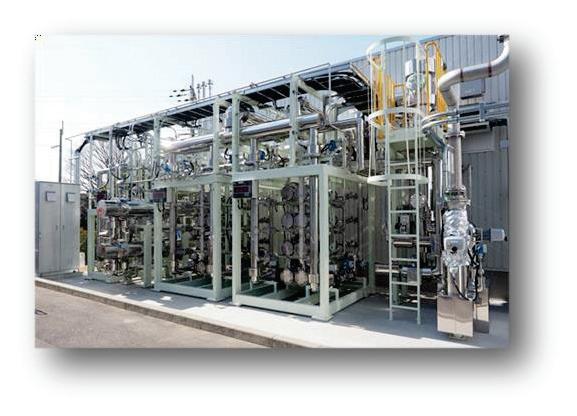
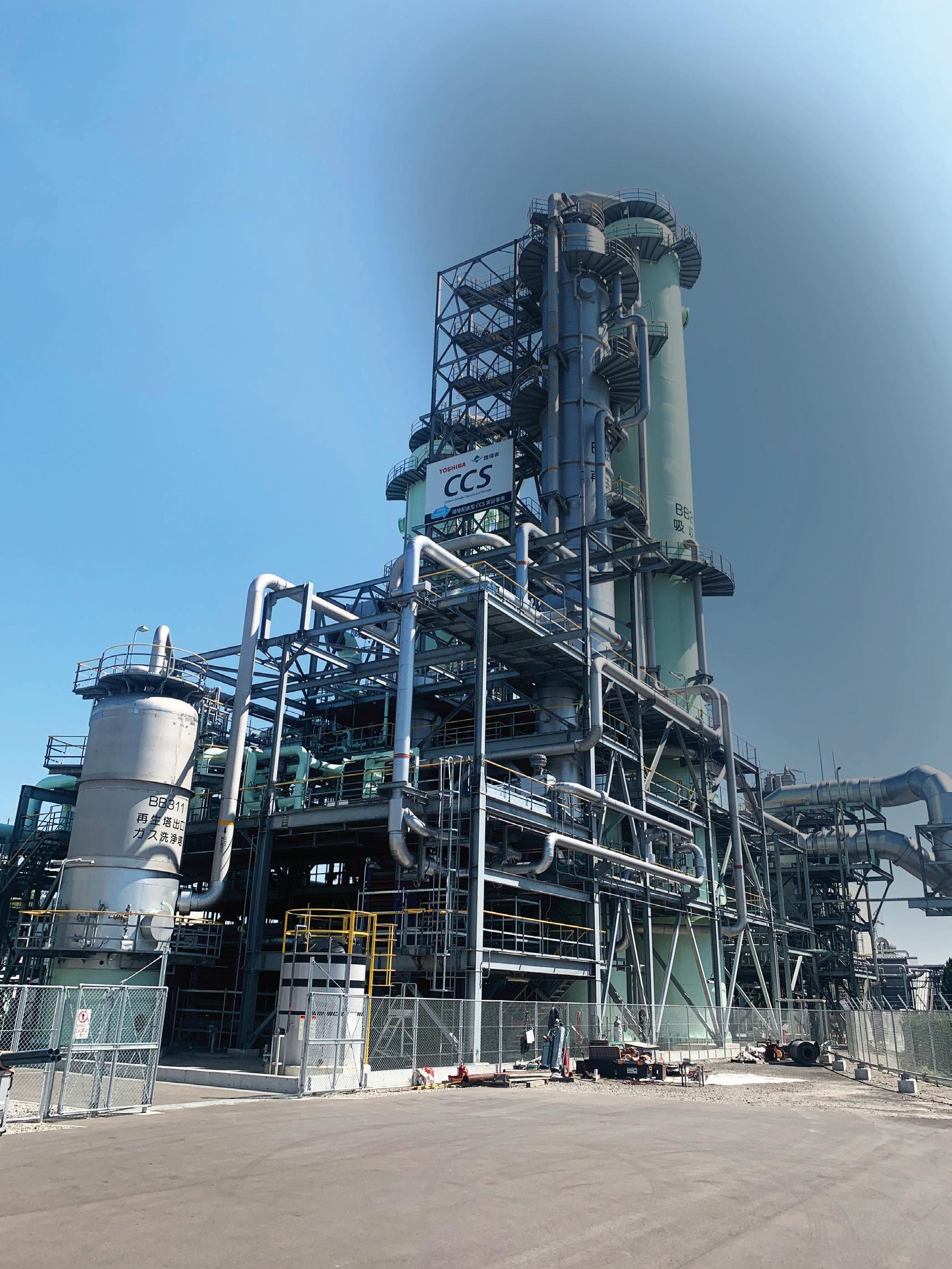
Toshiba has supported various CCUS plants and initiatives. The most notable, the Mikawa Post Combustion plant,* is a testament to the company's commitment to Carbon Capture, Utilization, and Storage. With the capability to capture over 600 tons of CO2 daily, which accounts for more than half of the plant's emissions, Mikawa serves as a model for efficiency and innovation. The plant's extensive experience, amassing nearly 13,000 hours, has been crucial in refining CCUS processes. Toshiba's broader efforts include R&D, plant design, and deployment of advanced CO2 capture technologies, such as Amine solvent solutions and P2C technology, reinforcing its dedication to a low-carbon future.
For more information on Toshiba’s approach to decarboniza-

Utilizing CBA Environmental Technology
Pennsylvania Accelerated Industrial Decarbonization Projects Utilizing Game-Changing, Low-Cost Cross-Sector Technology to Generate Clean Energy Jobs and Sustainable Products in Hard-to-Abate Sectors, while preserving Industrial Manufacturing Jobs
By Bruce L. Bruso
CBA Environmental Services has focused on providing low-carbon solutions to power generation, mining, and industrial manufacturing operations for the past 29 years.
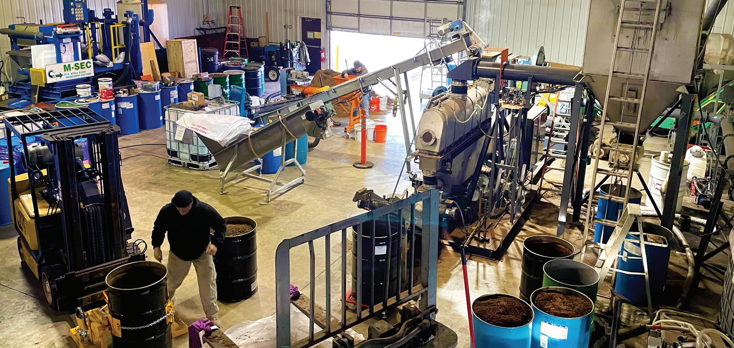
CBA Environmental Services is the developer of several Cutting-Edge Low Carbon Solutions proven, innovative technologies, including Remedial Coal Solutions, (RCS), Remedial Biomass Solutions, (RBS), and Biosolids-To- Renewable Fuels and Fertilizer, (BTRFF) Technologies. CBA operates the United States’ only working Commercial Industrial Decarbonization Pilot System located at our Corporate Campus and has completed over two hundred pilot tests ranging from coal and biomass to MSW, Biosolids and numerous industrial and agricultural wastes and residuals since 2008.

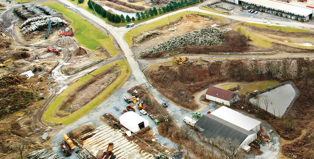
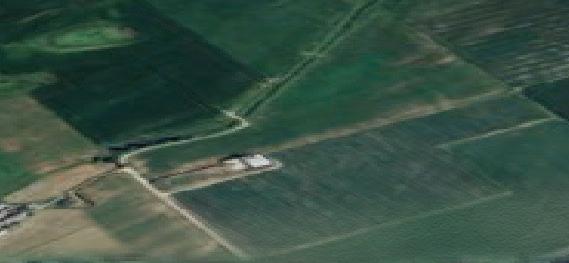
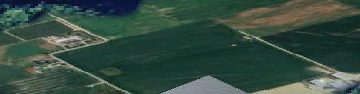
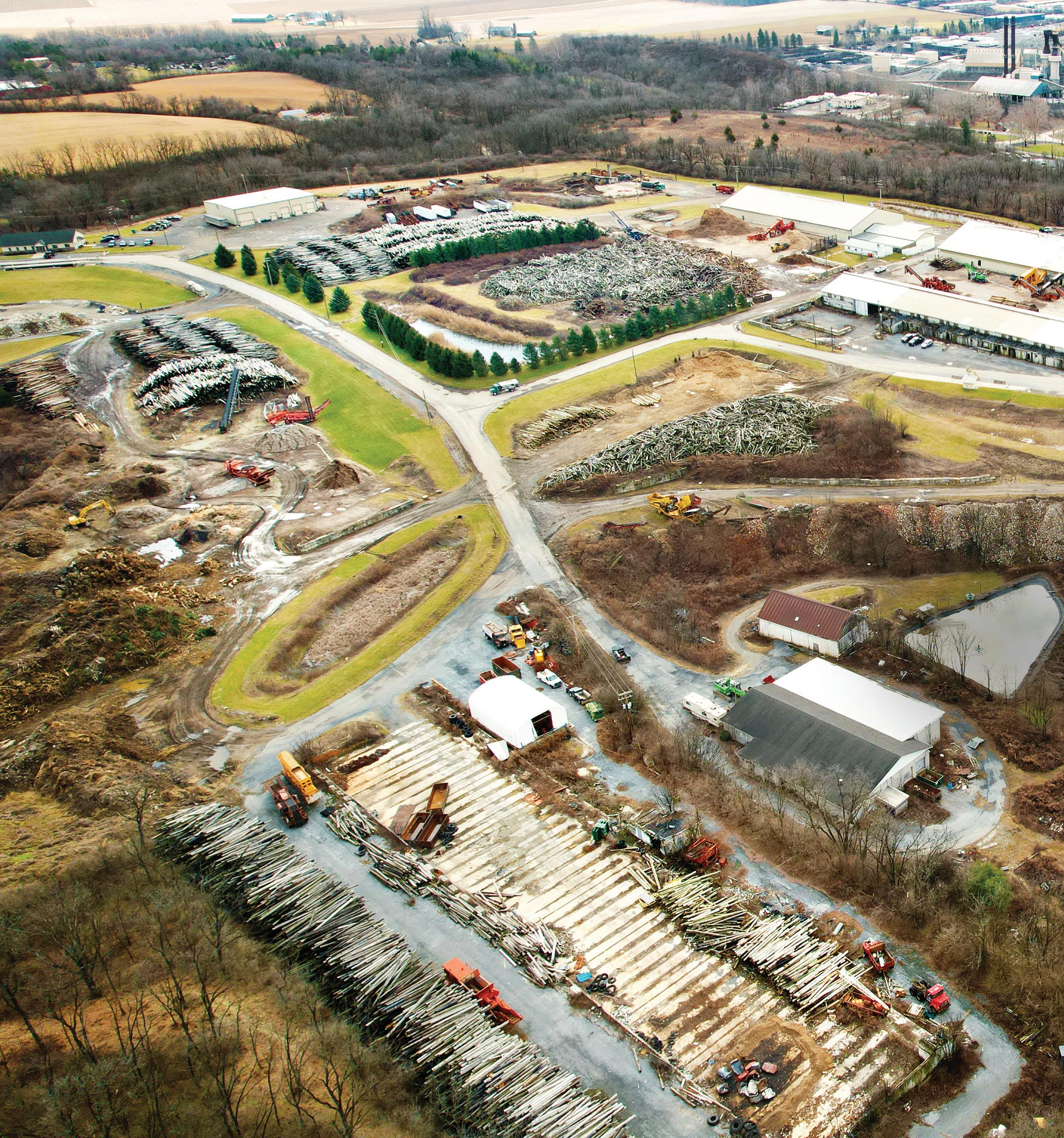
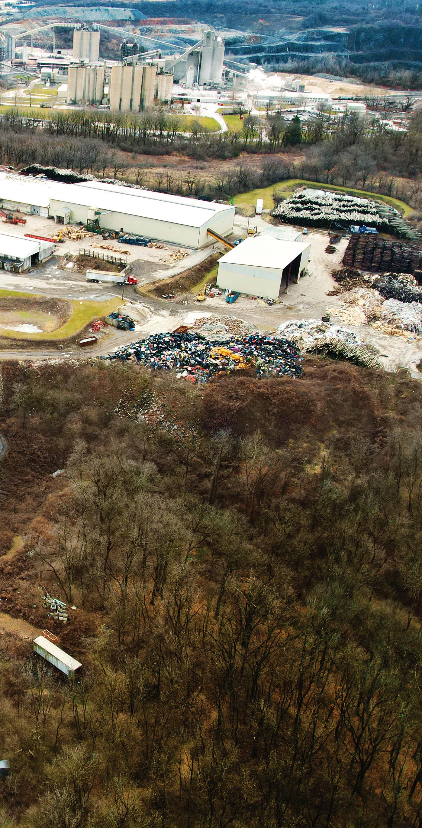
In addition to CBA’s ongoing Corporate Campus Pilot Testing and BioPolymer production capabilities, CBA is building two Commercial RBS CCUS systems. The first site is located at our 140-acre Commercial Wood Recycling and Material Recycling Facility (MRF) located in Berks County, PA where waste and green woody Biomass ranging from railroad crossties and power utility poles to pallets and tree trimmings are brought in, processed, and transformed into Decarbonized, Engineered Biofuel for Power Generation and Industrial heating and processing applications.
Historically, contaminates associated with wood-preserving process chemicals like creosote and pentachlorophenol have created disposal costs, PRP (Potentially Responsible Party) liability and fuel emissions hurdles for end users. CBA has removed these hurdles because of the CBA technologies now offering a complete recycling and beneficial reuse of otherwise end-of-life wood products destined for Landfill disposal as regulated waste under Federal and State Solid Waste regulations.
CBA’s Berks County facility intends to scale upthroughput of engineered solid Biofuels over the next three to five years while also transitioning into producing SAF, Drop-in Diesel liquid Biofuels, and Biopolymers utilizing a combination of existing feedstock on the ground plus incorporation of new and additional agricultural and forestry residuals like hemp crop components, waste plastics, and other cellulose-derived residuals inbound from the vast Mid-Atlantic region.
CBA’s Berks County facility is also considering the future installation of a Micro Turbine for the generation of renewable electricity for both existing power demand and the sale of power to the grid. The Micro Turbine would be fueled with decarbonized, engineered solid fuels produced at the facility.
The CBA Berks County site is strategically located just sixty miles North of the Port of Philadelphia, several refineries, and the intersection of several major pipelines. The CBA Berks site location offers strategic multiple benefits including the future export of decarbonized engineered fuels.
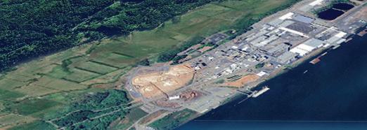
The second site is located on the property of one of the Country’s oldest Pulp and Paper mills, American Eagle Paper Mill, where contaminated paper fiber residual will be displaced from land application and landfill disposal, and upcycled into high-performance, Decarbonized Sustainable Biopolymers significantly reducing the Carbon Footprint, and providing robust options for a Circular Economy solution.
Since the beginning of time pulp and paper mills have managed their residuals either onsite or offsite generally looking to place in a beneficial use application. Spent paper mill residuals are recycled and re-pulped until they no longer have enough useful cellulose content. As time advanced and current residual management practices of land application and landfill disposal carry higher costs, carbon footprint, and incurred liability; Corporate mandates have evolved to move toward zero landfill objectives. Compounding the issue, the recent discovery of PFAS (Per and Polyfluoroalkyl Substances) otherwise labeled as “Forever Chemicals” has entered the arena and presents serious environmental concerns for the management of paper mill residuals.
The CBA RBS Technology not only decarbonizes the P&P residual by a minimum of 46%, but the process also reduces and destroys target PFAS compounds. The AEPM project will convert
paper mill residuals into Biopolymers and Bio Plastic additives that will reduce the need for fossil-derived carrier resins while upcycling and decarbonizing the cellulosic waste and displacing from land application and landfill disposal resulting in a more Sustainable Life Cycle Analysis, balance sheet liability cleansing, and a cost-positive benefit to AEPM. New plastic parts produced will be PFAS-free and consist primarily of Biopolymers.
CBA has intentionally developed low-carbon cross-sector solutions technologies so that hard-to-abate, carbon intense manufacturing does not have to change or alter their process thereby compromising product quality, performance, jobs, and reliability.
Benefits of the CBA Technologies are best described in three major categories:
1. Plant Optimization
2. Product Enhancement
3. Environmental, Sustainable, and Financial.
The CBA Technologies have far-reaching benefits across a wide array of hard-to-abate manufacturing, mining and mineral extraction, power generation, and steel, cement, fertilizer, chemical and plastics production.
The CBA Technologies are the lowest-cost cross-sector Carbon Capture Sequestration, and Utilization process commercially available today due to the simplicity and scalability of how it works,

SOURCE: CBA ENVIRONMENTAL SERVICES
its low capital and operating cost and the fact that additional valueadded commercial products are produced because of the process. Additionally, multiple manufacturing optimization values are realized generating real dollar savings across the entire hard-to-abate manufacturing processes.
The CBA technologies have a much lower Carbon Intensity (CI) score compared to other carbon capture technologies because most of the carbon capture and displacement is done chemically with a low-temperature thermal curing step.
The CBA technologies, including Remedial Coal Solutions, (RCS), Remedial Biomass Solutions, (RBS), and Biosolids to Renewable Fuel and Fertilizer, (BTRFF), are based on chemical decarboxylation utilizing a proprietary chemical reagent proven commercially time after time.
Prior to the chemical decarboxylation reaction, the chemical reagent upon contact with the feedstock instantly expands the micro and macro pore structure of the carbon-based feedstock allowing for rapid liquid-gas mass transfer of the CO2 molecules to contact the reagent. The proprietary reagent possesses the highest molecular absorption capacity for CO2 and CO2-e (CO2 - equivalent compounds) including target carboxylic acids.
Captured CO2 compounds are transformed into mineral salts that become commercial product ingredients and stand-alone com-
mercial products. The average CO2 reduction performance is 46% across feedstocks including fossil fuels like coal, non-fossil fuels like woody biomass, industrial and municipal sludges like Biosolids and papermill residual, and Municipal Solid Waste, (MSW).
The CBA technologies have been independently vetted and tested by the Electric Power Research Institute, (EPRI), University of North Dakota - Energy and Environmental Research Center, (UND-EERC), Combustion Resources Incorporated, (CRI), and GE Power Systems. Independent testing and verification conducting comparative combustion tests of raw versus treated feedstocks have consistently demonstrated average reductions of 46% of CO2 and CO2 -e compounds, excess steam, and electrical capacity of 25%, and significant reductions in other emissions profile pollutants such as NOx, SOx, and other hazardous pollutants.
The CBA technologies are pre-combustion applications facilitating ease of installation into a multitude of existing manufacturing processes, power generation, mining, and industrial applications. With a low CAPEX and OPEX combined with ease of scalability and zero interruption to existing processes, while providing additional sources of income and operational savings, the CBA technologies offer attractive low-carbon solutions to a broad range of industries.
Author: Bruce L. Bruso President & Chief Technology Officer
Environmental Services

We need to apply circular economy principles to accelerate CO2 storage
By Stewart Maxwell
Amidst an ongoing increase in global emissions, particularly across those generated from hard-to-abate industries, Carbon Capture and Storage (CCS) is increasingly recognized as imperative to achieving net zero.
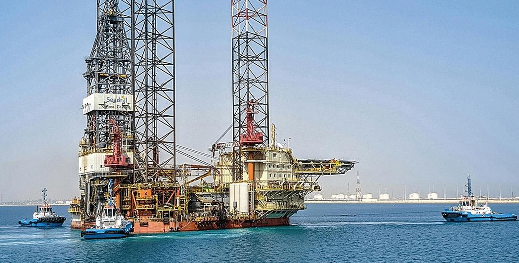
Offshore CCS projects are spreading across Europe with Norway recently offering two blocks in the North Sea for CO2 storage, and the UK announcing its CCUS Vision, meanwhile, there is a growing pipeline of North American projects centered around the Gulf of Mexico. The IEA estimates we will need to scale storage capacity from 40MT-5,000 MT a year to reach net zero and studies have identified some 13,000 gigatons of untapped CO2 storage capacity beneath the seabed.
But tapping into this will involve overcoming many hurdles, from cost-effectively and securely locating, sealing and re-abandoning legacy wells against CO2 leaks, to drilling new wells and implementing CO2 injection across storage sites of widely varying sizes and depths. Operators also face the challenge of adapting transportation pipes, pressures and flow rates to the unique properties of CO2, not forgetting the need to continuously monitor the integrity and safety of storage sites across their entire lifecycles.
Potential CO2 storage sites, such as depleted hydrocarbon reservoirs and saline aquifers, are typically scattered with legacy exploration, appraisal or production wells which could pose a potential leak risk depending on the abandonment approach deployed. For example, if zonal isolation across different formations for future CO2 storage was not considered.
Plugging and re-abandoning previously abandoned legacy wells with methods such as drilling a relief well to intersect and re-abandon the legacy well may be infeasible for some shallow formations, or where the well azimuth and depth are unknown. And while excavation may also seem viable, it quickly presents serious safety and technical difficulties. It does nothing to isolate re-abandonment loading from the compromised legacy well. These approaches can incur costs of over £18-20 million and take up to 95 days per well. Both are prohibitively slow and expensive for large sites with multiple wells and will be unsustainable without more cost-effective alternatives.
Operators also face the cost of drilling injection wells and installing CO2 injection platforms across everything from single wells in shallow waters to multiple wells in deeper waters. Once CO2 has been stored, ensuring it remains under the seabed introduces additional costs and requires the complex task of continually monitoring seismic and other events that could cause gas migration and lead to a CO2 leak.
Addressing all these risks in an economical and efficient way will require a unified, circular economy approach, adapting and sharing solutions across multiple applications from well re-abandonment and injection to CO2 monitoring.
Overcoming the many hurdles to CO2 storage entails an unprecedented effort to consolidate and combine resources across all project stages. At the storage stage, it is absolutely vital to eliminate risks and regulatory delays by quickly and efficiently safeguarding storage sites against CO2 leaks. A recent innovation enables multiple wells to be rapidly, cost-effectively and safely re-abandoned and sealed using a single re-usable and repeatable solution. The technology harnesses seabed surveying, well imaging, marking and tagging technologies to precisely locate wells beneath the seabed with centimeter-level accuracy.
A specially designed steel frame can then be positioned precisely over the well to enable safe vertical re-entry while a unique movement mechanism allows the frame to be re-adjusted to account for installation tolerances. The frame is designed to provide structural support for all equipment required for intervention and keep the weight of this equipment off the well to avoid damaging any corroded well casings. It also enables rapid installation of an environmental barrier to keep out sediment and debris and a pressure-retaining barrier to secure the well for re-plugging.

The ability to rapidly and safely vertically re-enter abandoned wells without excavating or drilling new relief wells could drive 80% cost reductions and over 50% time savings on well abandonment. By redeploying the system across multiple wells, these savings can be replicated without additional investment. The same system could be re-used to repurpose abandoned wells by installing fiber optics and geophones to transform them into monitoring wells to monitor CO2 plume migration within the formation or detect potential leaks before they breach the seabed.
Where a new CO2 injection platform is required, applying the modular lightweight principles pioneered in oil and gas, such as Aquaterra Energy’s Sea Swift provides significant benefits. The Sea Swift platform can be constructed in a range of configurations, from monopiles or conductor supported platforms for up to nine shallow-water
wells to jacketed structures injecting up to 15 wells in deeper waters.
Ultimately, a CCS injection platform works a lot like a production platform, but rather than up and out it is in and down so we have the basic principles of platform engineering well worked out.
Just as in offshore production, these lightweight, streamlined designs can be built and transported with existing local infrastructure and even installed with the same jack-up rig used to drill injection wells, significantly reducing costs.
Operational costs are also low as the platforms can be designed to be unmanned and self-powered from renewable sources such as wind and solar. If you’re going to the effort and cost of capturing and storing CO2 under the seabed permanently, the significant savings generated from a minimum facilities platform ensures that new emissions are kept to an absolute minimum.
In another scenario, where a developer is in the enviable position of having an existing platform
located on a reservoir suitable for CCS, a degree of brownfield engineering may be required to ensure that the platform can be used. This can range from simple changes to the topside equipment configuration to more detailed life extension studies. Aquaterra Energy is currently applying this life extension approach to the Nini platform, which is part of the broader Project Greensand led by INEOS. Project Greensand is a CCS initiative in the Danish North Sea, intending to store up to 1.5 million tonnes of CO2 annually by 2025 and potentially scale up to 8 million tonnes per year by 2030. We are working with INEOS to repurpose the platform for CO2 injection until 2045 confirming the viability of the structure and guiding the implementation of any necessary modifications to support CO2 injection and long-term storage.
Additionally, cutting-edge CO2 moni-
toring technologies can be used in tandem with new and repurposed platforms to monitor and safeguard storage sites against seismic effects or leaks. Monitoring, measurement and verification systems composed of fiber-optics, advanced monitoring systems and other sensors, alongside autonomous power sources can be deployed at CCS sites to provide early warning of hazards during injection. These sensors can be deployed to monitor wells post-injection, enabling remote long-term oversight of potential leaks or tremors across the lifecycle of storage sites, and offering end-to-end assurances against leaks.
Achieving net zero emissions is a critical global goal, with CCS playing a vital role. Offshore hydrocarbon fields, formerly
sources of fossil fuels, now offer significant potential for CO2 storage. However, nobody said tapping into this would be easy, and the industry faces challenges such as safety concerns, regulatory issues, and high costs.
Innovative solutions are essential to overcome these obstacles. Advanced techniques for sealing legacy wells, installing efficient CO2 injection platforms, and deploying state-of-the-art monitoring systems can make large-scale CCS viable. These innovations combined can reduce costs, enhance safety and speed up project timelines associated with the rollout of CCS at scale.

By Leo Duke and Diana Leane
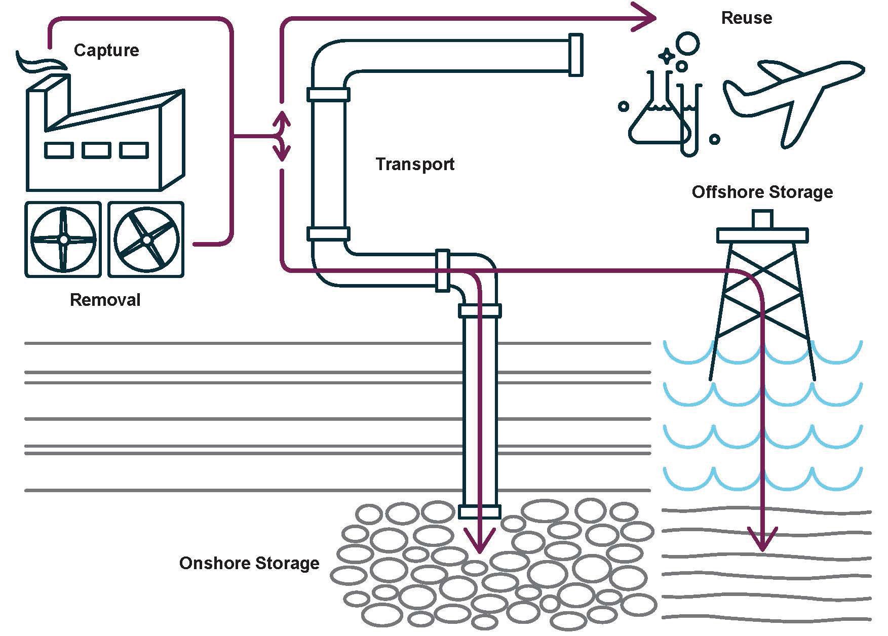
Carbon management technologies enjoy broad support: political, business, economic, and environmental leaders agree on the need for these technologies as part of the overall mix of technologies to address climate change. While there is no silver bullet to address the impacts of our changing climate, carbon management technologies -- which includes carbon capture from industrial and power facilities, carbon dioxide (CO2) removal directly from the atmosphere, transport, reuse, and safe and permanent storage of captured CO2 -- are an essential part of the effort to decarbonize our highest emitting sectors and help the US achieve net zero emissions by mid-century.
Over the past decade, the Carbon Capture Coalition and its 100+ members have helped to build this broad, diverse foundation and played a central role in advocating for a comprehensive portfolio of bipartisan federal policies to commercialize the full suite of carbon management technologies. Thanks to efforts from the Carbon Capture Coalition and allied organizations, a framework is in place for the large-scale deployment of carbon management technologies across emitting sectors. The Inflation Reduction Act (IRA), coupled with the historic investments for carbon management in the Bipartisan Infrastructure Law (BIL), has turbocharged interest in carbon capture at industrial facilities and power plants and directly from the air.
With these historic investments leading to increasing projects across the country, engaging local communities and providing accessible information on the clean energy transition is of the utmost importance. The Carbon Action Alliance, an initiative of the Great Plains Institute, is a growing network of governmental, industry, labor, environmental, and community partners working to inform the public about carbon management opportunities, address decarbonization challenges, support project deployment, and benefit communities. The Alliance provides resources and tools accessible to the public through resources on its website, through convenings, and events.
Today, there are 14 domestic commercial-scale facilities with the capacity to capture and store approximately 20 million metric tons of CO2 per year, representing nearly half of the global deployment of the technology to date. Historically, carbon capture technology has been primarily applied in those industrial sectors that emit a pure stream of CO2, such as ethanol production or natural gas processing. However, enhancements to the 45Q tax credit have turbocharged interest in applying carbon management technologies across emitting sectors.
This August marked the second anniversary of the IRA, a critical milestone for the section 45Q tax credit, the foundational policy for the deployment of carbon man-
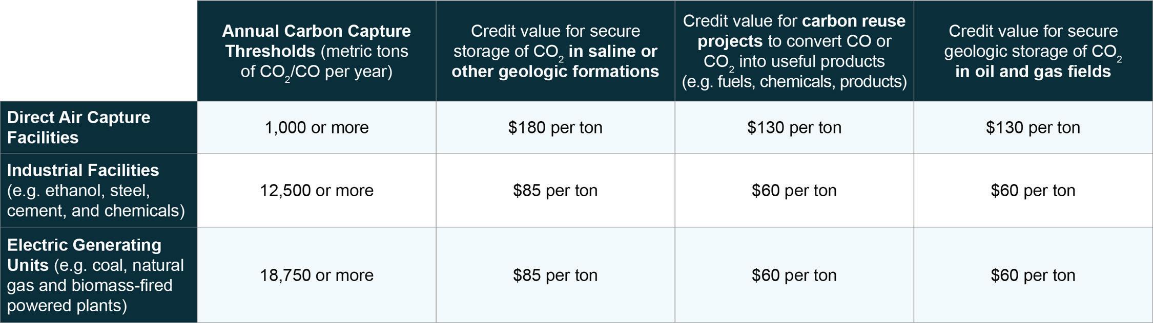
agement technologies. The 45Q tax credit provides a credit on a per-metric ton basis for carbon that is captured from emitting facilities or directly from the air and then permanently stored or reused to make useful products. Today, thanks to these historic policies in support of carbon management, there are now nearly 220 announced carbon management projects in the US across a range of emitting sectors.
Below, we detail several recent technopolicy developments for the deployment of these climate-crucial technologies across power, industry, CO2 transport, and promising developments in carbon removal.
In the US power sector, the deployment of carbon management will play an essential role in addressing emissions from existing
power plants, where fossil fuel generation currently provides around 60 percent of total power. Looking forward, carbon capture deployment in the power sector will provide flexible, low-emissions energy resources in regions with growing shares of renewable energy sources.
The Biden administration has recognized the role that carbon capture will play across emitting facilities. In April, the administration published final rules to regulate greenhouse gas emissions from existing coal-fired and new natural gas power plants. In the rule, EPA recognizes carbon capture technologies as a key climate mitigation tool to reduce CO2 emissions and criteria air pollutants from coal and natural gas electric generating units.
Additionally, carbon management technologies are not optional for decarbonizing the industrial sector. According to EPA emissions data, the industrial sector is responsible for 30 percent of domestic emissions when associated emissions from electricity use at industrial facilities are included. Nearly half of industrial emissions occur in just three sectors: steel, cement, and basic chemicals. These sectors provide the essential building blocks for modern lifestyles and provide familysustaining jobs.
Certain industrial processes have limited or no emissions reduction strategies beyond carbon capture. This is for two primary reasons. First, the industrial sector relies on fossil fuels to provide high-temperature heat that cannot be easily substi-
tuted with renewable sources. Additionally, many industrial processes directly emit CO2, meaning these emissions are directly produced and emitted by the chemical or physical conversion of raw materials into finished goods and cannot be abated without carbon capture. These so-called process emissions are responsible for approximately one-quarter of the emissions from the industrial sector.
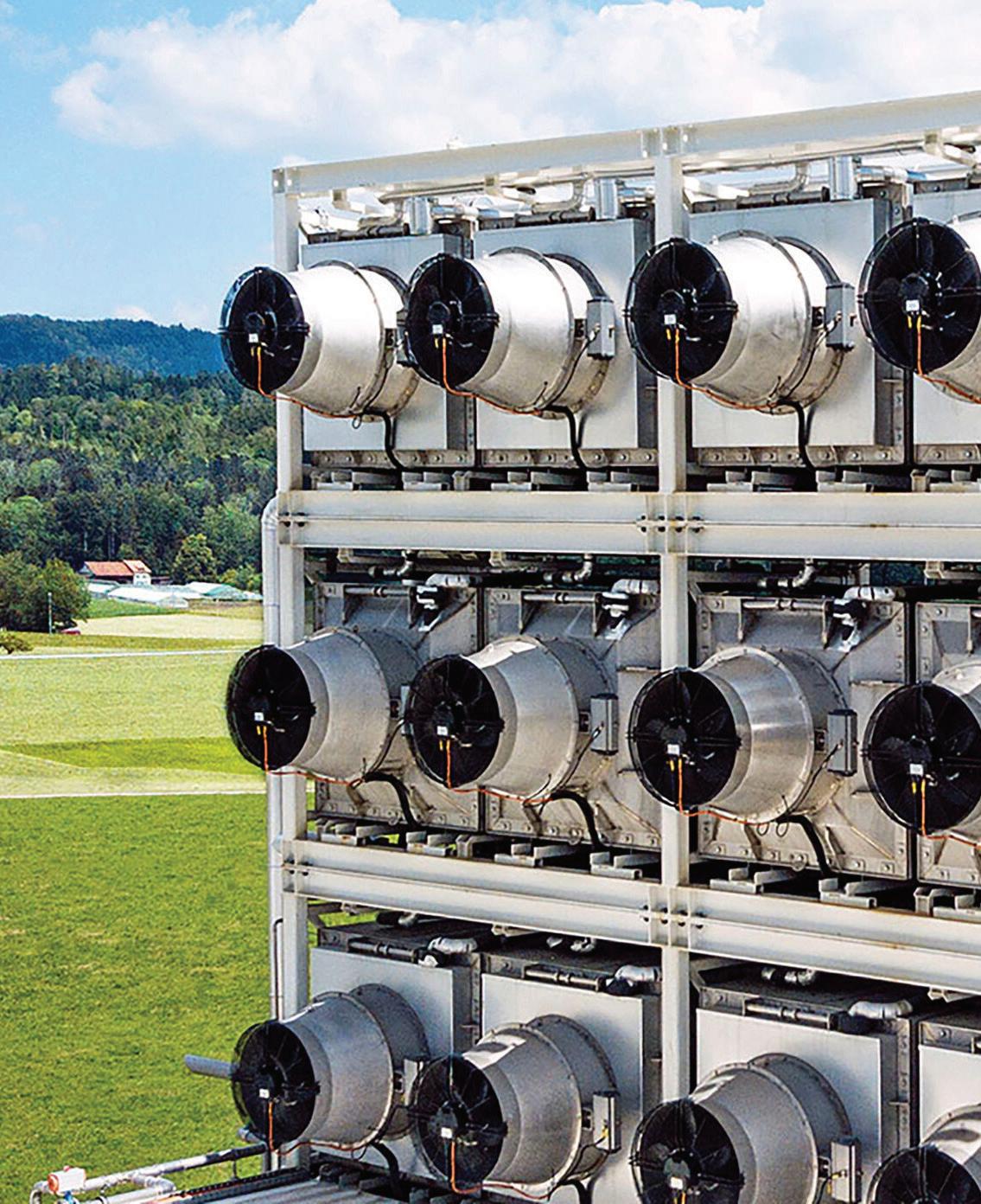
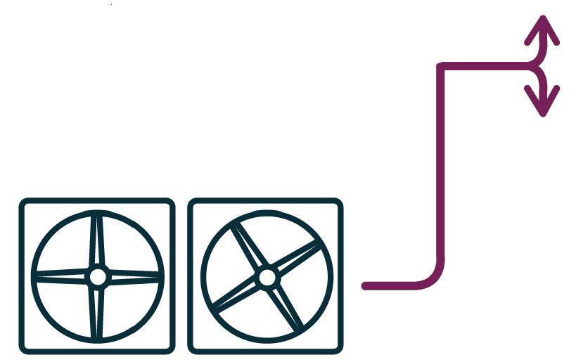
Direct Air Capture (DAC) technology directly captures carbon dioxide (CO2) from the atmosphere to store underground or convert into useful products. DAC uses large fans to pass large amounts of ambient air over materials to separate out the carbon dioxide.
IRA enhancements to 45Q provide additional incentives to deploy carbon management technologies in higher-cost but absolutely crucial sectors to decarbonize. According to the DAC Coalition, there are approximately 30 operational DAC facilities, ranging from 1 metric ton per year to nearly 40,000 metric tons per year. While this progress is encouraging, to meet net zero emissions by midcentury, according to the International Energy Agency, this nascent but important sector must be scaled up globally to capture more than 85 million tons of CO2 per year in 2030 and nearly 1 gigaton (or billion tons) of CO2 per year by 2050. Programs like DOE’s investment of $3.5 trillion into Regional DAC Hubs will
help jumpstart the industry by creating regional hubs for direct air capture technologies.
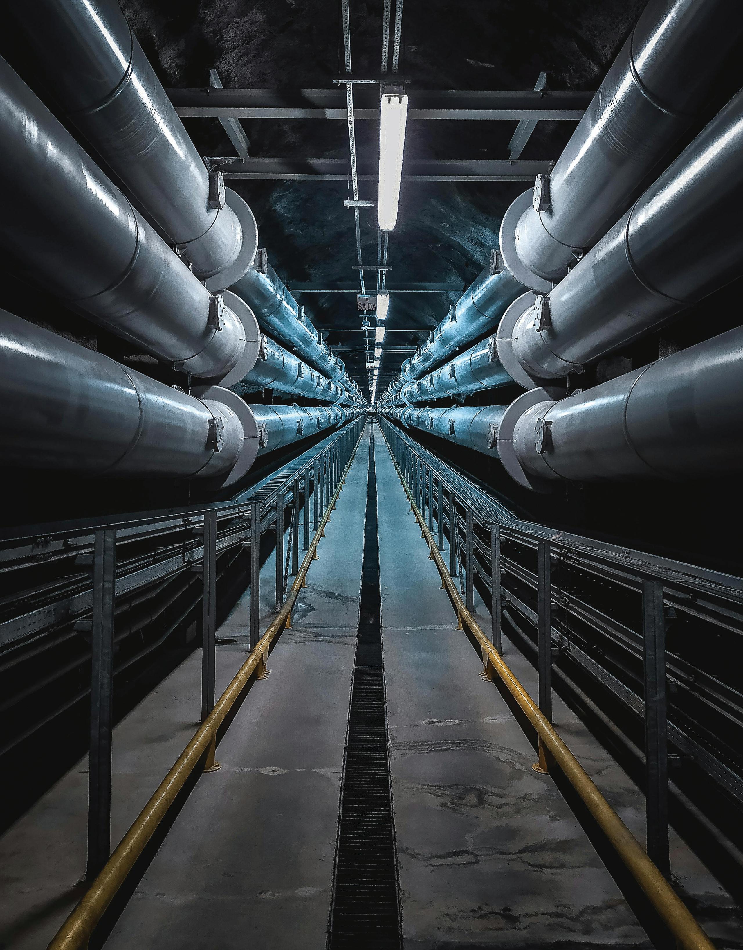
Last but not least, one critical piece links all the steps from capturing CO2 from facilities or the air to storing it underground or reusing it in new products: transport infrastructure. CO2 pipelines are the backbone of the economywide deployment of carbon management technologies across the United States.
The continued safe operation of CO2 pipelines is paramount as the industry expands. With over 5,000 miles of CO2 pipelines in operation, incidents are rare, and the industry has maintained an excellent safety record, according to a new issue brief from the Great Plains Institute. However, as carbon management projects grow, we must ensure the continued safe operation of these systems. To that end, the federal Pipeline and Hazardous Materials Safety Administration (PHMSA) is working on updated regulations to ensure safety standards as this network expands as additional capture and removal facilities come online. As the nation continues to invest in carbon management technology, ensuring the safety of CO2 pipelines is crucial. The forthcoming PHMSA regulations and federal funding efforts must continue the commitment to building a safe and sustainable carbon transport infrastructure.
In parallel, the BIL provided DOE $2.1 billion through the Carbon Dioxide Transportation Infrastructure Finance and Innovation Act (CIFIA) to offer access to
capital for large-capacity, common-carrier carbon dioxide transport projects. To meet net zero emissions by midcentury, we must see a networked system of CO2 pipelines transporting CO2 from emitting sources or the air, to secure geologic storage.
The Inflation Reduction Act, coupled with the groundbreaking investments made in the Bipartisan Infrastructure Law, is a historic step forward in fostering the economywide deployment of carbon management technologies. These technologies are necessary to achieve midcentury emissions reduction targets while safeguarding highwage jobs that sustain families and communities and ensuring the long-term viability of key domestic industries. Reflecting on the impact of these laws, one thing is clear — the passage of these laws marked the beginning, not the end, of necessary efforts to build the portfolio of policies for carbon management technologies and fulfill the promise of this landmark legislation.
A case study examining how industrial collaboration can decarbonize the Midwest region.
By Marcos Miranda, Carbon Solutions
To meet climate targets and regulation requirements, there is a need to rapidly decarbonize different sectors such as transportation, agriculture, and industry. The industrial sector is, unsurprisingly, comprised of many different industries such as iron & steel, manufacturing, chemical manufacturing, cement, and ethanol. Some industries, such as the cement industry, have higher costs associated with capturing carbon dioxide (CO2) emissions and could be more hesitant to engage with carbon capture and storage opportunities. Other industries, like the ethanol industry, have lower capture costs and relatively pure streams of CO2 that could encourage them to join CO2 Capture and Storage (CCS) projects early on.
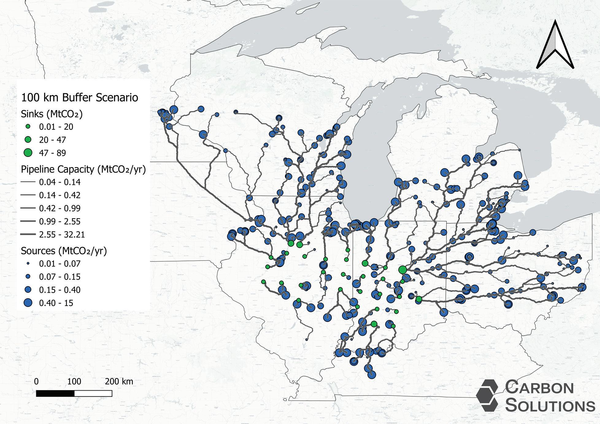
Carbon Solutions explored how industries like ethanol could interact with CCS networks, in a highlevel case study in the Midwest. Carbon Solutions first identified 92 ethanol facilities in Wisconsin, Minnesota, Iowa, Indiana, Ohio, Illinois, Kentucky, and Michigan. Next, buffer ranges of 20, 30, 40, 50 and 65 km were applied with the center of each buffer on an ethanol facility. When buffers overlapped between two or more ethanol facilities they were aggregated into one large buffer. Carbon Solutions then selected those sources that fell within each buffer zone to create different sets of sources. A total of five distinct scenarios that used the different sets of buffer sources were run using Carbon Solutions SimCCSPRO tool.
SimCCSPRO is an economic-engineering mixed integer linear programming (MILP) model that optimally solves when, where, and how much CO2 to capture, transport, and store. SimCCSPRO takes a user-defined annual capture target, user-defined groups of sources and sinks, and a weighted cost surface for pipeline routing as inputs. The model then provides a globally optimized solution, CO2 transport pipeline length in km, unit costs ($/tCO2) for capture, transport and storage, and unit costs across each scenario. SimCCSPRO takes inputs from other Carbon Solutions models such as estimated CO2 storage capacity and storage cost (from SCO2TPRO), estimated CO2 capture costs and capture emissions (from CO2NCORD), and transport routing and costs (through CostMAPPRO). These are all used by SimCCSPRO to determine globally optimal CCS networks and their associated costs given the desired capture target.
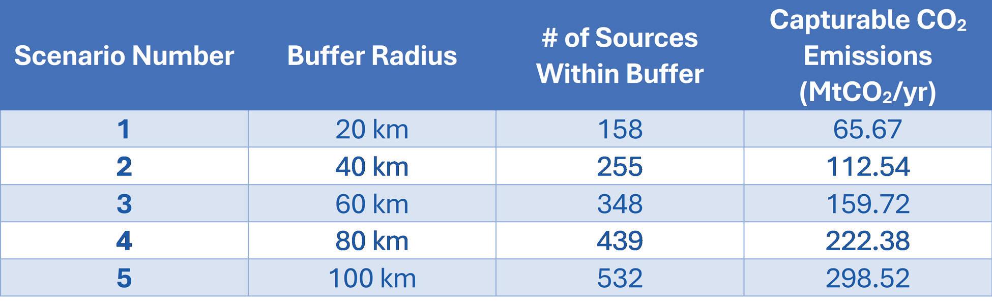
First Carbon Solutions explored what other industries exist around chosen ethanol facilities in the Midwest. For buffers of 20 km, 40 km, 60 km, 80 km, and 100 km there are 158, 255, 348, 439, and 532 facilities respectively with capturable CO2 emissions going from 65.67 MtCO2/yr to 298.52 MtCO2/yr. Within 20 km (~12.5 miles) of ethanol facilities, gas and coal power plants and glass manufacturing facilities have the highest counts. Expanding to 60 km (~37 miles) from ethanol facilities, gas and coal power plants and glass manufacturing facilities are joined by pulp and paper processing and food and agricultural facilities as having the highest counts of all facilities. At 100 km, (~62 miles) the five industries with the highest facility count are: gas power plants, coal power plants, iron and steel manufacturing, pulp and paper processing, and glass manufacturing. Refineries also have a sizeable number of facilities within the 100 km buffer.
These facility counts don’t necessarily correspond to the highest capturable emissions. While glass manufacturing has among the highest number of facilities count within each of the buffer ranges, the cumulative capturable emissions from glass manufacturing, as a percent of total capturable emissions across all facilities, is between 0.53% to 0.88%. Alternatively, coal and gas power plants account for almost 62% of all available capturable emissions in a 100km radius of ethanol facilities. For the same buffer range, iron and steel manufacturing and refineries account for approximately 8.7% and 5.7% of capturable emissions respectively.
When looking at the five scenarios that Carbon Solutions ran, a few items stand out. First, as the buffer range increases, the amount of deployed pipeline increases from 3,727 km (~ 2,316 miles) of deployed pipeline using sources within a buffer of 20 km to 15,140 km (~9,408 miles) of pipeline when using sources within a 100 km buffer of ethanol facilities. This correlates with capturing emissions from facilities that are farther away from ethanol facilities and then transporting the captured CO2 to more centralized storage options. Interestingly, most networks deploy in a way that brings captured CO2 emissions from farther away sources and injects them into more centralized storage options located in Illinois and Indiana. Because Illinois and Indiana have favorable subsurface geology with relatively high capacities and low estimated storage costs, this favorable geology helps offset the increase in costs that comes with deploying more pipelines to connect faraway sources. Further, these pipelines can be designed to be larger and thus carry more CO2, taking advantage of economies of scale.
This assumption is supported when looking at the unit costs for each network. Transport costs begin at
$16.62/tCO2 when using sources in a 20 km buffer and are $18.27/tCO2 when using sources in a 100 km buffer. Across the same buffer interval, storage costs start from $9.19/tCO2 at 20 km and decrease to $5.48/tCO2 at 100 km, demonstrating how networks utilize larger and longer pipelines to transport CO2 to centralized, high-capacity, lower-cost sinks. Capture cost steadily increases as the buffer range extends farther from ethanol facilities, which is partially explained by looking at facility counts, summarized earlier. As the buffer range increases, the number of facilities for industries that have higher estimated capture costs increases. For example, there are only two cement facilities within 20 km of ethanol facilities while there are seven within 100 km. An increase in the number of facilities from industries that have higher capture costs partially explains why capture costs increase. Ultimately, total costs for CCS networks range from $75.74/tCO2 to $78.42/ tCO2 for networks centered on ethanol facilities in the Midwest. This range indicates that CCS networks that cen-
ter around ethanol facilities could be a viable option for encouraging CCS adoption in the Midwest.
Carbon Solutions explored what CCS networks focused on ethanol facilities in the Midwest would look like. There are numerous facilities from different industries that surround ethanol facilities within buffer ranges of 20 to 100 km. Some of these industries have higher estimated capture costs, which might discourage them from participating in early CCS efforts. Yet these findings suggest that industries like ethanol can support CCS efforts. The total costs of the CCS networks here are encouraging and suggest that CCS in the Midwest can be advantageous for those who choose to participate.
Author: Marcos Miranda Research Scientist at Carbon Solutions marcos.miranda@carbonsolutionsllc.com