15 minute read
LE MISURE DI TEMPERATURA: TERMOMETRI MECCANICI E TERMORESISTENZE
In ogni settore industriale è essenziale garantire la corretta temperatura sia per il corretto trattamento delle materie prime, sia per il buon funzionamento delle attrezzature impiegate, in termini di prestazioni, effcienza e sicurezza operativa. Analizziamo in questo primo articolo termometri meccanici e termoresistenze.
Alessandro Brunelli*
Advertisement
L’unità di misura della temperatura è il kelvin (K)che è la frazione 1/273,16 dell’intervallo di temperatura tra il punto triplo dell’acqua e lo zero assoluto, e può essere così formulato:1
1 K = 1 / 273,16 Temperatura termodinamica del punto triplo dell’acqua In pratica vengono utilizzate varie scale di misura e quindi diverse unità per la misura della temperatura, quali: tC = temperatura espressa nella scala Celsius: che assegna 0 °C al punto di fusione del ghiaccio e 100 °C al punto di ebollizione dell’acqua: l’intervallo è diviso in 100 parti ciascuna delle quali è denominata grado Celsius (°C). tK = temperatura espressa nella scala Kelvin: che è una scala assoluta riferita alla scala
Celsius: lo zero della scala coincide con lo zero assoluto = 0 K = - 273,15 °C. tF = temperatura espressa nella scala
Fahrenheit: che assegna 32 °F al punto di fusione del ghiaccio e 212 °F al punto di ebollizione dell’acqua: l’intervallo è diviso in 180 parti ciascuna delle quali è denominata grado
Fahrenheit (°F). tR = temperatura espressa nella scala
Rankine: che è una scala assoluta riferita alla scala
Fahrenheit: lo zero della scala coincide con lo zero assoluto = 0 °R = - 459,67 °F. I misuratori di temperatura più utilizzati nelle misure industriali sono i seguenti: •Termometri meccanici •Termoresistenze •Termistori •Termocoppie •Trasmettitori La Tabella al termine della trattazione dei diversi misuratori di temperatura, riporta a compendio le loro caratteristiche riassuntive in termini di: •Limite di impiego tipico •Campo di misura tipico •Precisione tipica
allo scopo di fornire una rapida guida per la scelta e selezione dei vari misuratori nelle diverse applicazioni industriali. Termometri a dilatazione (meccanici)
I termometri a dilatazione, comunemente detti meccanici, sfruttano le variazioni provocate dalla temperatura sul volume di materiali solidi, liquidi, gas e vapori. Nei vari materiali, vengono utilizzate le relazioni funzionali seguenti:
Nei solidi: - La variazione di due diversi materiali metallici a diverso coeffciente dilatazione termica:
Termometri bimetallici
Nei liquidi: - La variazione di pressione provocata da dilatazione termica del liquido a volume costante:
Termometri con elemento elastico a molla
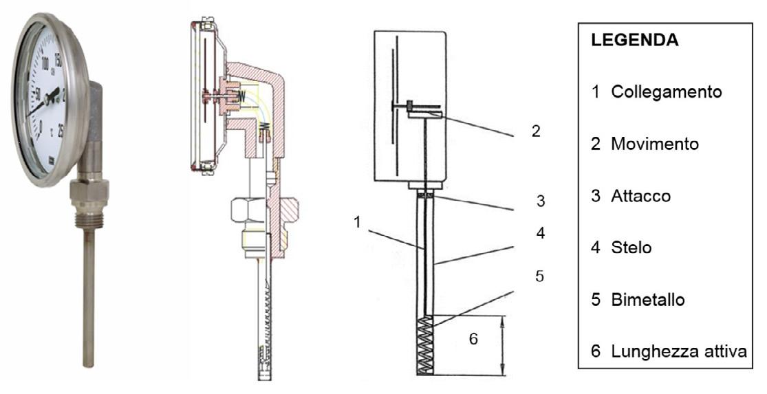
Nei gas e vapori: - La variazione di pressione provocata da espansione termica del gas a volume costante: Termometri con elemento elastico a molla I termometri industriali esistono nelle tipologie a colonna, scarsamente utilizzati data la loro fragilità, e a quadrante, invece ampiamente utilizzati nelle misure locali di processo, che sono disciplinati come campi e precisione di misura dalla Norma Europea EN 13190 in classi di precisione 1 e 2%. La costruzione dei termometri a quadrante, può essere delle due tipologie seguenti: - a lamina-bimetallica, nei termometri a dilatazione di solidi; - a bulbo-capillare, nei termometri a espansione di liquidi, gas o vapori. Il dispositivo indicatore frontale del valore di temperatura è analogo a quello normalizzato per i manometri, ed è così azionato: - nel caso dei termometri bimetallici: direttamente dalla lamina bimetallica spiralata e vincolata all’estremità interna del pozzetto termometrico a contatto con il processo da misurare (Figura 1); - nel caso dei termometri ad espansione di fuido (gas o vapore): direttamente dal fuido stesso contenuto nel pozzetto termometrico, che attraverso il capillare, porta le variazioni di pressione dovute alle variazioni della temperatura da rilevare, all’elemento manometrico elastico a molla, posto nella cassa del termometro indicatore. Sono strumenti adatti per misure locali, anche in zone con pericolo di esplosione, o incendio, in quanto non necessitano per il loro funzionamento di alcuna energia esterna.
Fig. 1 Vista esterna e sezione interna di un termometro bimetallico
Vantaggi • Autoindicanti • Basso costo • Buona precisione • Adatti per ambienti ostili Svantaggi • Misure locali o a distanza senza trasmissione della misura • Elevati tempi di risposta rispetto i sensori elettrici
1 Un kelvin è la differenza di Temperatura Termodinamica corrispondente a una differenza di energia termica pari a kB J, dove kB è il valore della costante di Boltzmann in J/K secondo la recente defnizione del 2019 della CGPM: Conferenza Generale dei Pesi e Misure (Conférence Générale des Poids et Mesures), e il valore della costante di Boltzmann corrisponde a 1,38064852 × 10⁻²³ J/K.
Le termoresistenze (in inglese RTD: Resistance Temperature Detectors) sono dei termometri a resistenza metallici che si basano sulla nota relazione: [W] dove: R = resistenza del conduttore [W] r = resistività del conduttore [W . m] l= lunghezza del conduttore [m] A = area del conduttore [m2] Se varia la temperatura, varia la resistenza del conduttore Rt, che rispetto la resistenza iniziale Ro, che può essere formulata mediante l’approssimata relazione seguente: [W]
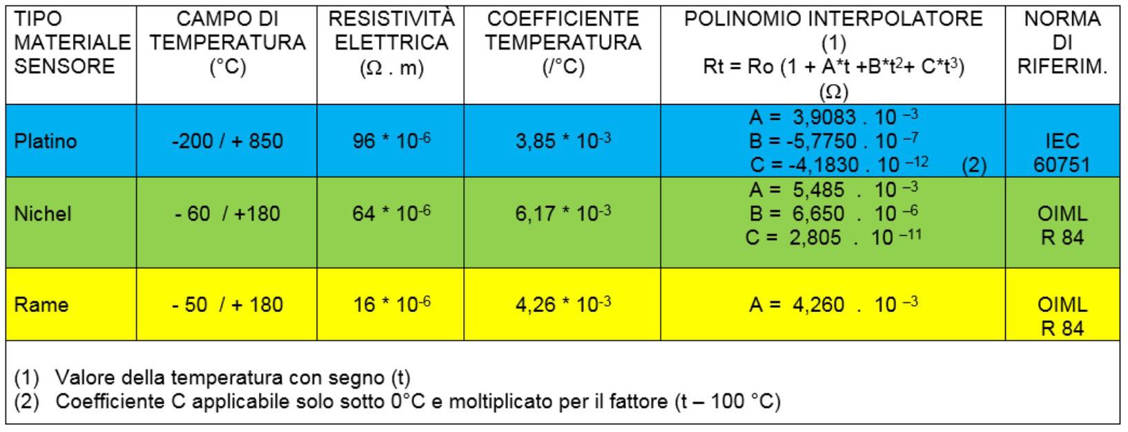
dove: Rt = resistenza alla temperatura di t °C [W] Ro = resistenza alla temperatura di 0°C [W] a = coeffciente di temperatura [/°C] t = temperatura in °C [°C] Il coeffciente di temperatura a dipende dal tipo di materiale metallico costituente la termoresistenza ed è praticamente un coeffciente medio calcolato nel campo 0 ÷ 100 °C mediante la relazione seguente: [/°C] Industrialmente sono praticamente utilizzati i materiali metallici riportati in Tabella 1, le cui caratteristiche peculiari sono le seguenti:
Platino (Pt): utilizzato nella maggior parte delle applicazioni per la sua maggior resistenza all’ossidazione, resistività elettrica e ottima riproducibilità.
Nichel (Ni): utilizzato raramente nelle applicazioni con modeste variazioni di temperatura, perché presenta minor resistenza all’ossidazione.
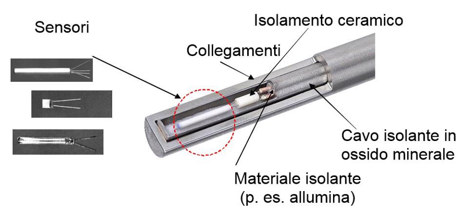
Rame (Cu): utilizzato ancor più raramente nelle applicazioni con modeste variazioni di temperatura, sebbene abbia un coeffciente di temperatura costante rispetto il Platino e il Nichel. Sensori delle termoresistenze (Figura 2)

a)A flo avvolto in capsule di vetro: su un substrato isolante di vetro utilizzato in applicazioni con temperature fno a 400 °C.
b) A flo avvolto in capsule di ceramica: su un substrato isolante di ceramica utilizzato in applicazioni con temperature fno a 600 °C. c)A flm depositato su substrato isolante: e ricoperto esternamente di uno strato di ceramica per applicazioni fno a 500 °C:
Fig.2. Vista sezionata di una termoresistenza con vari sensori di misura

Il materiale più impiegato nella costruzione dei sensori di temperatura altrimenti detti elementi sensibili è come predetto il Platino, che manifesta un coeffciente di temperatura tipicamente pari a: -a > 3,925 * 10 –3 / °C per termometri campioni -a = 3,850 * 10 –3 / °C per termometri industriali Il valore di resistenza Ro a 0 °C vale tipicamente: -2,5 – 25 W per i termometri campioni: dati i migliori strumenti di misura impiegati e l’elevata temperatura di impiego (fno 1000 °C) -5 ÷ 1000 W per i termometri industriali: dati i normali strumenti di misura impiegati
e la più bassa temperatura di impiego (fno 500 °C) Difatti aumentando la temperatura di impiego della termoresistenza, aumenta anche l’effetto di auto riscaldamento, altrimenti detto in inglese “self heating” del termometro, dovuto all’effetto Joule, e quindi proporzionale al fattore R * I2, dove: - R, è appunto il valore di resistenza del termometro - I, è invece il valore di corrente di misura della resistenza dello stesso termometro che normalmente è di 1 mA nelle più generali applicazioni delle misure industriali. Normalizzazione delle termoresistenze (vedasi Tabella 1 e 2):
Termoresistenze al Platino: Norma
Internazionale Elettrotecnica IEC 60751
Termoresistenze al Nichel e al Rame:
Norma Internazionale Metrologica
OIML R 84 Sistemi di misura delle termoresistenze
Il collegamento a 2 fli è poco utilizzato in quanto introduce errori grossolani di misura, se la resistenza dei fli di collegamento non è trascurabile rispetto quella del termoelemento: difatti se si considera un termoelemento RTD
Tab. 1 Limiti di temperatura e polinomi interpolatori delle termoresistenze normalizzate

Tab. 2 Limiti di temperatura e classi di tolleranza delle termoresistenze normalizzate

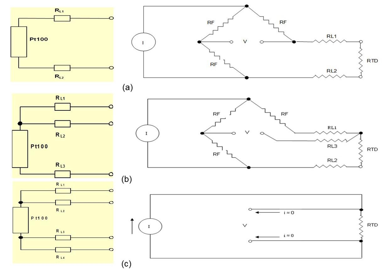
(Pt 100) collegato con fli di rame da 0,5 mm2 distante 5 m, la resistenza complessiva del collegamento andata e ritorno sarà circa sui 400 mW, che equivale a un errore strumentale maggiore di 1 °C (essendo la sensibilità delle termoresistenze Pt 100 equivalente a 385 mW/°C) il che è superiore alle classi di tolleranza previste (Tabella 2) e pertanto vanno seguite le seguenti confgurazioni misura (Figura 3): (a)A 2 fli: Sconsigliabile, perché può provocare errori superiori a 1 °C anche per collegamenti brevi, in quanto le resistenze di linea di andata RL1 e di ritorno RL2 si sommano alla RTD (Pt100). (b)A 3 fli: Consigliabile, perché la confgurazione a 3 fli compensa la resistenza dei fli di collegamento, in quanto RL1 e RL2 essendo su due lati contigui del ponte non provocano variazioni di V; difatti RL1 si somma alla resistenza fssa del ponte RF e RL2 si somma a quella variabile RTD. (c)A 4 fli:
Consigliabile per la maggior precisione in quanto è la cosiddetta misura Volt_
Amperometrica, che viene effettuata sempre con una corrente I di 1 mA, che provoca una tensione di uscita V sempre proporzionale alla RTD a prescindere dalla resistenza dei fli di collegamento.
Fig. 3 Confgurazione tipica a sinistra e di misura a destra dei collegamenti delle termoresistenze

Vantaggi •Ottima precisione •Buon campo di temperatura (per le termoresistenze al Platino) Svantaggi •Alta sensibilità agli urti ed alle vibrazioni •Elevato tempo di risposta •Elevato costo (rispetto le termocoppie)
*Alessandro Brunelli
Esperto in Automazione, Strumentazione, Taratura e Sicurezza degli Impianti Industriali. Segretario CEI SC 65 B: Misura e Controllo dei Processi Industriali alebrunelli767@gmail.com
Keywords: Termometri meccanici, Termoresistenze, Termistori, Termocoppie, Trasmettitori di Temperatura, EN 13190, RTD, Pt100, P1000, Collegamento a 2/3/4 fli
TEMPERATURE MEASUREMENTS - PART ONE
In every industrial sector it is essential to ensure the correct temperature both for the correct treatment of raw materials and for the proper functioning of the equipment used, in terms of performance, effciency and operational safety. We analyze in this frst article dedicated to process measurements some of the most common temperature sensors. Alessandro Brunelli* The unit of measurement of temperature is the kelvin (K) which is the fraction 1/273.16 of the temperature range between the triple point of water and absolute zero, and can be formulated as follows2: 1 K = 1 / 273.16 Thermodynamic temperature of the triple point of water In practice, various measurement scales and therefore different units are used for temperature measurement, such as: tC = temperature expressed on the Celsius scale: which assigns 0 °C to the melting point of ice and 100 °C to the boiling point of water: the range is divided into 100 parts each of which is called Celsius degree (°C). tK = temperature expressed on the Kelvin scale: which is an absolute scale referred to the Celsius scale: the zero of the scale coincides with the absolute zero = 0 K = - 273,15 °C. tF = temperature expressed in the Fahrenheit scale: which assigns 32 °F to the melting point of the ice and 212 °F to the boiling point of water: the range is divided into 180 parts each of which is called Fahrenheit degree (°F). tR = temperature expressed on the Rankine scale: which is an absolute scale referring to the Fahrenheit scale: the zero of the scale coincides with the absolute zero = 0 °R = - 459.67 °F. The most used temperature meters in industrial measurement are the following: - Mechanical thermometers - Heaters - Thermistors - Thermocouples - Transmitters The Table at the end of the treatment of the different temperature meters, shows in summary their characteristics in terms of:
- Typical use limit - Typical measuring range - Typical accuracy in order to provide a quick guide for the selection and selection of various gauges in different industrial applications. Expansion thermometers (mechanical
Expansion thermometers, commonly referred to as mechanical thermometers, exploit the variations caused by temperature in the volume of solid materials, liquids, gases and vapors. In the various materials, the following functional relationships are used: In solids: - The variation of two different metallic materials with different thermal expansion coeffcient: Bimetal thermometers In liquids: - The pressure variation caused by thermal expansion of the liquid at constant volume: Thermometers with spring elastic element In gases and vapors: - The pressure change caused by thermal expansion of the gas at constant volume: Thermometers with spring elastic element Industrial thermometers exist in column thermometers, which are scarcely used due to their fragility, and dial thermometers, which are widely used in local process measurements, which are regulated as measuring ranges and accuracy by the European Standard EN 13190 in accuracy classes 1 and 2%. The construction of dial thermometers can be of the following two types: - foil-bimetal, in solids expansion thermometers; - bulb-capillary, in expansion thermometers of liquids, gases or vapours. The frontal temperature value indicator device is similar to the one normalized for pressure gauges, and is thus operated: - in the case of bimetal thermometers: directly from the spiral bimetal foil and bonded to the inner end of the thermowell in contact with the process to be measured (Figure 1); - in the case of fuid expansion thermometers (gas or steam): directly from the fuid itself contained in the thermowell, which, through the capillary tube, carries the pressure variations due to the temperature variations to be measured, to the spring elastic manometric element, placed in the case of the thermometer indicator. These instruments are suitable for local measurements, even in areas with danger of explosion or fre, as they do not require any external energy for their operation. Advantages - Self-indicating - Low cost - Good accuracy - Suitable for hostile environments Disadvantages - Local or remote measurement without transmission of measurement - High response time compared to electrical sensors Thermorexistences
Resistance thermometers (RTD: Resistance Temperature Detectors) are metal resistance thermometers based on the known relationship:
[W]
where: R = conductor resistance [W] r = conductor resistivity [W . m] l = conductor length [m]
A = conductor area [m2] If the temperature changes, the resistance of the conductor Rt changes, which compared to the initial resistance Ro, which can be formulated by the following approximate relationship:
[W]
where: Rt = temperature resistance of t °C [W] Ro = temperature resistance of 0°C [W] a = temperature coeffcient [/°C] t = temperature in °C [°C] The temperature coeffcient depends on the type of metal material making up the resistance thermometer and is practically an average coeffcient calculated in the range 0 ÷ 100 °C by means of the following relation:

[/°C] Industrially the metallic materials shown in Table 1 are practically used, whose peculiar characteristics are the following: -Platinum (Pt): used in most applications for its greater resistance to oxidation, electrical resistivity and excellent reproducibility. -Nickel (Ni): rarely used in applications with modest temperature variations, because it has less resistance to oxidation. -Copper (Cu): even more rarely used in applications with modest temperature variations, although it has a constant temperature coeffcient compared to Platinum and Nickel. Resistance thermometer sensors (Figure 2) a)Wire wrapped in glass capsules: on an insulating glass substrate used in applications with temperatures up to 400 °C. b)Wire wrapped in ceramic capsules: on an insulating ceramic substrate used in applications with temperatures up to 600 °C. c)Film deposited on an insulating substrate: and externally covered with a ceramic layer for applications up to 500 °C: The material most used in the construction of temperature sensors otherwise known as sensitive elements is as predicted Platinum, which has a temperature coeffcient typically equal to: - > 3.925 * 10 -3 / °C for sample thermometers -= 3,850 * 10-3 / °C for industrial thermometers The resistance value Ro at 0 °C is typically valid: -2,5 - 25 Ohm for sample thermometers: Given the best measuring instruments used and the high operating temperature (up to 1000 °C) -5 - 1000 Ohm for industrial thermometers: given the normal measuring instruments used and the lowest operating temperature (up to 500 °C) In fact, by increasing the temperature of use of the resistance thermometer, also increases the effect of self-heating, otherwise known in English as “self heating” of the thermometer, due to the Joule effect, and therefore proportional to the factor R * I2, where: -R, is precisely the resistance value of the thermometer -I, on the other hand, is the resistance measurement current value of the thermometer itself, which is normally 1 mA in general industrial measurement applications.
Normalization of resistance thermometers (see Table 1 and 2):
84 - Platinum Resistance Thermometers: International Electrotechnical Standard IEC
- Nickel and Copper Resistance Heaters: International Metrological Standard OIML R 60751
Tab. 1. Temperature limits and interpolating polynomials of normalized resistance thermometers

Tab. 2 Temperature limits and tolerance classes of normalized resistance thermometers
Resistance thermometer measuring systems
The 2-wire connection is little used as it introduces gross measurement errors if the resistance of the connecting wires is not negligible compared to that of the thermoelement: In fact, if we consider an RTD thermoelement (Pt 100) connected with 0.5 mm2 copper wires at a distance of 5 m, the total resistance of the return connection will be about 400 m, which is equivalent to an instrumental error greater than 1°C (being the sensitivity of Pt 100 thermoresistances equivalent to 385 m/°C) which is higher than the tolerance
classes provided (Table 2) and therefore the following measurement confgurations must be followed (Figure 3): (a)2-wire: Not recommended, because it can cause errors of more than 1 °C even for short connections, as the forward line resistors RL1 and return line resistors RL2 are added to the RTD (Pt100). (b)3-wire: Recommended, because the 3-wire confguration compensates for the resistance of the connecting wires, as RL1 and RL2 being on two adjacent sides of the bridge do not cause changes in V; in fact RL1 is added to the fxed resistance of the RF bridge and RL2 is added to the variable resistance RTD. (c)4 wires: Recommended for greater precision as it is the so-called Volt_Amperometric measurement, which is always carried out with a current I of 1 mA, which causes an output voltage V always proportional to the RTD regardless of the resistance of the connecting wires. Advantages -Excellent accuracy -Good temperature range (for Platinum resistance thermometers) Disadvantages -High shock and vibration sensitivity -High response time -High cost (compared to thermocouples) Keywords: Mechanical thermometers, Resistance thermometers, Thermistors, Thermocouples, Temperature transmitters, EN 13190, RTD, Pt100, P1000, 2/3/4 wire connection


