architecture selected works 2009 --- 2023 portfolio jiangshen Huang Email: Jasonhuang0121@gmail.com Please take a look at my high-resolution portfolio online: https://issuu.com/jiangshenhuangsaic-2016/docs/jiangshen_huang_-_architecture_portfolio?fr=sYmY5ZTYwMzcyNTE
AS AN ACCOMPLISHED ARCHITECTURAL DESIGNER


I have dedicated my career to crafting designs that prioritize meticulous attention to detail and the use of high-quality materials in order to achieve a harmonious balance of design elements. With over five years of experience in the industry, I possess a deep understanding of the fundamental principles of design and construction.


My passion for architecture was ignited when I read an article by Kengo Kuma, whose philosophy of creating architecture that is both visually appealing and functional resonated deeply with me. In order to fully comprehend his words, I immersed myself in the art of sushi-making, spending two years learning from a Japanese sushi chef with 40 years of experience. Through this experience, I developed an eye for detail and an artistic sensibility that I now bring to my design work.
I pursued a Master of Architecture program at the School of the Art Institute of Chicago, where I gained comprehensive architectural knowledge and skills, as well as honed my artistic sensibilities. Following my studies, I completed internships at several leading architecture firms in Chicago before joining KPN Architects, LLC in Baltimore, where I have worked on a variety of projects across different sectors.

Throughout my career, I have developed proficiency in various software programs and am able to effectively communicate my design ideas through both hand sketching and 3D modeling. Additionally, I possess a strong understanding of sustainability and strive to incorporate sustainable design principles into my work whenever possible.

In my free time, I enjoy oil painting, sketching, playing the violin, and making sushi. These experiences inform my design philosophy and inspire me to create functional and aesthetically pleasing spaces.

I am committed to pursuing my architecture license in the United States and am eager to bring my skills and expertise to a new role where I can continue to grow as a professional and contribute to a team’s success.

LIANG JIANG SALES DEPARTMENT DESIGN CHICAGO OBAMA PRESIDENTIAL CENTER COMMUNICATION ARTS & HUMANITIES BUILDING
PRINCE GEORGE’S COMMUNITY COLLEGE MARLBORO HALL
RASH FIELD REDEVELOPMENT
SUBURBAN ORTHODOX CONGREGATION TORAS CHAIM
REISTERSTOWN METRO WABASH TOWN CENTER
FURNITURE
02 03 04 05 06 08 09 10 12 13 14 1/2 1/2 1/2 1/2 1/2 1/2
CHICAGO MIDTOWN ATHLETIC CLUB KULA BELGRADE IN SERBIA FINE ARTS & THE DOORS OF CULTURE
DESIGN PRACTICES & CNC INTEGRATED FABRICATION
ARCHITECTURE PORTFOLIO : SELECTED WORKS 2009-2023 CONTENTS LIBRARY, THEATRE & FACULTY OFFICE COMPLEX 01 THE VILLAGES OF WHITE MARSH 07 NEW ECOLOGIES OF SUSTAINABILITY 11 the villages of white marsh Rear Elevation Long View 19
LIBRARY, THEATRE & FACULTY OFFICE COMPLEX
Studio Architect l Associate

KPNARCHITECTS, llc 2017 - Present
Brief Description of Project
Size : 63,00sf
Design Start : 2018
Constructions Start : 2020
Setting : Academic
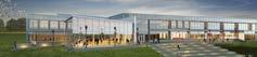
The Library, Performing Arts + Faculty Complex will be a new 63,000 GSF mixed use building for Stevenson University’s Owings Mills, Maryland campus. The new theatre department will serve to expand the drama program with a black box theatre, scene + costume shops, rehearsal studios and dressing rooms. Common spaces throughout the complex encourage group collaboration while private study areas allow for individual study. The integration of transparency between the different spaces of the complex allow for viewing “behind-the-scenes” performances such as the scene shop and the library book processing area. Included in the complex is: 26,000 SF Library, 17,000 SF Theater Department & 32 Faculty + Staff Offices

Responsibility
As a part of the team, my primary responsibility was to develop design ideas, submit design documents and prepare construction documentation, including door + hardware schedules, stair schedules and details, millwork + casework details, roof plans, exterior details, and interior details.
CLIENT
Stevenson University, Inc. 1525 Greenspring Valley Road Stevenson, MD 21153 877.468.6852
DEVELOPER & BUILDER
David S. Brown Enterprises, Ltd. 100 Painters Mill Rd, Owings Mills, MD 21117 410.363.3434
01
UP PR M AD 2 PROMENADE EN AN E AZA WALKWAY WALKWAY AMPITHEATER LOADING UNLOADING T.O.SLAB 559.9' T.O.SLAB 559.9' T.O.SLAB 559.9' T.O.SLAB 556.4' T.O.SLAB 556.4' T.O.SLAB 559.9' T.O.SLAB 559.9' T.O.SLAB 559.4' T.O.SLAB 557.9' T.O.SLAB 556.4' T.O.SLAB 557.9' T.O.SLAB 556.4' ELEVATION 557.4' T.O.SLAB 559.4' T.O.SLAB 559.9'T.O.SLAB 559.9' T.O.SLAB 559.4' T.O.SLAB 557.9' T.O.SLAB 557.9' T.O.SLAB 559.9' T.O.SLAB 558.9' SP-01 SP-01 SP-02 SP-03 SP-04SP-04 SP-05 SP-05 T.O.SLAB 557.9' T.O.SLAB 557.9' T.O.SLAB 556.0' T.O.SLAB 556.0' T.O.SLAB 559.9' ELEVATION 556.9' ELEVATION 556.0' ELEVATION 555.0' ELEVATION 554.0' T.O.SLAB 550.0' T.O.SLAB 559.4' ELEVATION 556.4' T.O.SLAB 556.0' T.O.SLAB 559.9' T.O.SLAB 557.83' T.O.SLAB 556.26' T.O.SLAB 554.69' T.O.SLAB 553.12' T.O.SLAB 551.55' T.O.SLAB 550.0' SP-06 BUILDING FOOTPRINT ROA WAY S E C V L DRAW NGS FIRE ACCESS ROAD, SEE CIVIL DRAWINGS CONTROLJOINTS(CJ)15'0"ONCENTER(OC)TYP CJ17'5"OC 11' 6" 12' 6" C O N T R O L O N T S O C 130 1 2CJ9"OCCJ12'0"OC CJ15'0"OC SP-07 SP-07 SP-07 SP-07 SP-07 SP-07 CJ 90 OC SP-08 SP-08 SP-08 C 11 O C T Y P T.O.SLAB 559.4'0 D E E P T E R R A C E S SP-07 GCWTH TERACEDGE CJ13OC C13-6 OC CJ1212 OC CJ -9/2 OC 83 3 C J T O B U L D N G C10- 48OCP 10- 44OC C16- 38O16- 0OCP DGE TO BU LD I NG 76 1/8 T RRACE STA R TO BU LD NG 66" STA R W DT 53 / 8" RAMP W I DTH 51 1 / 2" NW EGE C J 33 O C C J 43 O C C 18 O C ABCDEFGHJK C:\Users\oliver\Documents\(Revit Files)\Revit 2019\SUL 191031 Construction Documents_Central_owclemons3rd.rvt KEYNOTES SP-01PLANTING SP-02EMERGENCY SP-03BGETRANSFORMER SP-04DUMPSTERS SP-05BIKERACK SP-06SCREEN SP-07LINEOFBUILDING SP-08STAIRSWITH ABCDEFGHJK KPN ARCHITECTS PROJECT NUMBER: No.DateRevisions/Submissions hereby certify that these documents were prepared or approved by and that am a duly licensed professional architect under the laws State of Maryland, License No.: Exp. Date: SEAL: Date: Scale: Drawn/CheckBy: LM 7 6 5 4 3 8 9 954 Ridgebrook Road, Suite 120 Sparks, MD 21152 410.683.7004 ACOUSTICAL ENGINEER: 1220 North Fillmore Street, Suite 360 Arlington, VA 22201 703.243.6301 Shen Milsom & Wilke THEATRE CONSULTANT: 300 Raritan Ave, 2nd Floor Highland Park, NJ 08904 732.333.8003 Stages Consultants, LLC 3DesignDevelopmentCheck 02.28.2019 4DesignDevelopmentSet 04.10.2019 550%ConstructionDocuments 06.12.2019 675%ConstructionDocuments 07.31.2019 7100%ConstructionDocuments 11.04.2019 G001 1815 COVER SHEET Author November4,2019 LIBRARY, THEATRE & FACULTY OFFICE COMPLEX STEVENSON UNIVERSITY 100% CONSTRUCTION DOCUMENTS SET Owing Mills North Campus 11200 Gundry Lane Owings Mills, Maryland 21117 LOCATION MAP VICINITY PLAN NOT TO SCALE N N
PROJECTSITELOCATION SITE PLAN LOCATION MAP

UP UP UP UP 14 15 16 17 13 12 AC AD AE AF 11 BA BC 20 21 22 BB 10 18 CD CC CB A301 A301 3 A301 142 151 140B 141 168 169 161 154 166 154A 102 165 103 135 133 137 106 110A 107 108 153 121 122 123 126 125 124 120 118 104 111 136 166C 162 163A 163 140 119 S1131102A 112 E1134 S2110C A201 A201 109 30 31 32 33 34 35 132 151A 151B CA CE CF CG CH 152 110B 110 164 167 168A 169A 150 WALKWAY PROMENADE WALKWAY WALKWAY PROMENADE ENTRANCEP AZA NEOFCONCOURSEABOVE 37 38 AB AA A201 1 A201 101B 23 MATCH ESE A11 MATCH LINE SEE A112 MATCHLNESEE A1 MATCH LINE SEE A113 MATCH L NE SEE A112 MATCH L I NE SEE A111 36 100A 101A 116115114113 117 166B 100B A313 WALKWAY A313 5 A313 A313 No.DateRevisions/Submissions CIVIL, SITE, UTILITY ENGINEER: 30"X42", IT IS A REDUCED PRINT hereby certify that these documents were prepared approved me, and that am duly licensed professional architect under the laws the State of Maryland, License No.: Exp. Date: SEAL: Date: Scale: Drawn/CheckBy: 7 6 5 4 3 2 1 8 STRUCTURAL ENGINEER: 215 Schilling Circle, Suite 102 Hunt Valley, MD 21031 410.785.7423 Carroll Engineering MEP, FIRE PROTECTION, ENERGY ENGINEER: 757 Frederick Road, Suite 300 Catonsville, MD 21228 410.869.7282 SRBR Engineering 954 Ridgebrook Road, Suite 120 Sparks, MD 21152 410.683.7004 Matis Warfield DESIGN ARCHITECT: 309 Edgevale Road Baltimore, MD 21210 443.571.4435 Vertical Architecture Enterprises ACOUSTICAL ENGINEER: 1220 North Fillmore Street, Suite 360 Arlington, VA 22201 703.243.6301 Shen Milsom Wilke THEATRE CONSULTANT: 300 Raritan Ave, 2nd Floor Highland Park, NJ 08904 732.333.8003 Stages Consultants, LLC 3DesignDevelopmentCheckSet 02.28.2019 4DesignDevelopmentSet 04.10.2019 550%ConstructionDocuments 06.12.2019 675%ConstructionDocuments 07.31.2019 7100%ConstructionDocuments 11.04.2019 AM C:\Users\oliver\Documents\(Revit Files)\Revit 2019\SUL 191031 Construction Documents_Central_owclemons3rd.rvt 1/16"1'-0" OVERALL FLOOR PLAN - LEVEL 1 Author November4,2019 LIBRARY, THEATRE & FACULTY OFFICE COMPLEX STEVENSON UNIVERSITY 100% CONSTRUCTION DOCUMENTS SET Owing Mills North Campus 11200 Gundry Lane Owings Mills, Maryland 21117 109ELEVATORMACHINEROOM 110FRONTLIBRARY 110ALIBRARYREADINGAREA 110BLIBRARYQUIETSTUDYAREA 110CLIBRARYFLEXSPACE 111MULTIPURPOSEINSTRUCTIONROOM 112ELECTRICALROOM 113LIBRARYDIRECTOR 114ADMIN 115ADMIN 116ADMIN 117MEETINGROOM 118SHAREDRESOURCESTAFFBREAKROOM 119ITROOM 120PROCESSINGWORKAREA 121BOOKTRUCKDISEMBARKINGAREA 122STORAGE 123CARTSTORAGE 124STAFF 125STAFF 126STAFF 130CORRIDOR 131MOTHER'SROOM 132JANITORCLOSET 133EVENTSPACESTORAGE 134SPRINKLERROOM 135LOADINGDOCKTHEATRESTAGING 136MAINELECTRICALROOM 137DININGBOHCATERING 140SCENESHOP 140ASOUNDLOCK 140BSETMATERIALSTORAGE 141TOOLSTORAGE 142FACULTYOFFICE 150PRE-FUNCTION 151BLACKBOX 151ASOUND&LIGHTLOCK 151BSOUND&LIGHTLOCK 151CBLACKBOXSEATINGSTORAGE 152THEATREWING 153MAINIT 154COSTUMESHOP 154ACOSTUMESHOPSTORAGE 160CIRCULATION 161GREENROOM 162ACTINGLAB 163STAFF 163ASTAFF 164ENVIRONMENTALSERVICES 165PROPSTORAGE 166REHEARSALMOVEMENTSPACE 166ASOUNDLOCK 166BAVCLOSET 166CREHEARSALCLOSET 167ELECTRICALROOM 168DRESSINGROOM 168ATOILETSHOWER 169DRESSINGROOM 169ATOILETSHOWER E1-1ELEVATOR S1-1STAIR S2-1STAIR UP 14 15 16 17 13 12 AC AD AE AF 11 BA BC 20 21 22 BB 10 18 CD CC CB A301 A301 A301 211 250 260H 260A 262 201 260R 261R 261K 260J 260K 260L 260M 260N 260P 262A 223 234 232 231 230 233 211A 216215214 213 204 235 217 222 221 242 S2203 202 252 254 245 A201 A201 261H 261G 261E 261D 261C 261B 261A 251 255 212 219 224 253 218 S1261L 261M 261N 261P 260F 260E 260D 260C 260B 30 31 32 33 34 35 CA CE CF CG CH 210C 210B 210 220 200B 240B 240A 260 260G 261J 261 240 37 38 OPENTO BELOW OPENTO BELOW OPENTO BELOW OPEN TO BELOW OPENTO ABOVE OENTO ELOW OPENTO BELOW AB AA CATWALK CATWALK A201 1 A201 4 BLACK BOXGALLERY 23 LOWROOF MATCHLNESEE A1 MATCH LINE SEE A122 MATCHLNESEE A 3 MATCH LINE SEE A123 MATCH L NE SEE A122 MATCH L I NE SEE A121 255A 36 217A 217B A313 A313 A313 LOWROOF A313 7 6 5 4 3 2 8 AM C:\Users\oliver\Documents\(Revit Files)\Revit 2019\SUL 191031 Construction Documents_Central_owclemons3rd.rvt OVERALL FLOOR PLAN -LEVEL 2 ROOMSCHEDULE ROOMNO. 200UPPERLOBBY 200AFOYER 200BCONCOURSE 201JANITORCLOSET 202WOMENSRESTROOM 203MENSRESTROOM 204OUTDOORTERRACE 210QUIETREADINGROOM 210ALIBRARY 210BQUIETSOFTSEATING 210CQUIETREADINGROOM 211ARCHIVESREADINGROOM 211AARCHIVALCOLLECTIONS 212ELECTRICALROOM 213STUDYROOM 214STUDYROOM 215STUDYROOM 216STUDYROOM 217EVENTSPACE 217ASTORAGE 217BCOATS 218TOILET 219ITROOM 220CORRIDOR 221SMALLMEETINGROOM 222MEDIUMMEETINGROOM 223LARGEMEETINGROOM 224BOILERROOM 230RECEPTION 230APRINTERAREA 231DEAN 232ADMIN 233ADMIN 234DEAN 235STORAGE 240ASOUND&LIGHTLOCK 240BCONTROLBOOTHLIFT 242SOUNDEQUIPMENT& 245MECHANICALLOFT 250FACULTYCOMMONS 251ELECTRICALROOM 252ITROOM 253JANITORCLOSET 254MOTHER'SROOM 255STAFFBREAKROOM 255ASHAREDRESOURCE 256COURTYARD 260CIRCULATION 260ACENTRALIZEDSTORAGE 260BFACULTY 260CFACULTY 260DFACULTY 260EFACULTY 260FFACULTY 260GFACULTYCOMMONS 260HFACULTY 260JFACULTY 260KFACULTY 260LFACULTY 260MFACULTY 260NFACULTY 260PFACULTY 260RFACULTY 261CIRCULATION 261AFACULTY 261BFACULTY 261CFACULTY 261DFACULTY 261EFACULTY 261GFACULTY 261HFACULTY 261JFACULTYCOMMONS 261KFACULTY 261LFACULTY 261MFACULTY 261NFACULTY 261PFACULTY 261RFACULTY 262ADJUNCTFACULTYCOMMONS 262AFACULTYCOMMONS E1-2ELEVATOR S1-2STAIR S2-2STAIR S2-2ASTAIRVESTIBULE OVERALL FLOOR PLAN - LEVEL 1 OVERALL FLOOR PLAN - LEVEL 2
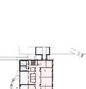
SCHEMATIC DESIGN PLAN - LEVEL 1
SCHEMATIC DESIGN PLAN - LEVEL 1

Montgomery Park Business Center 1800 Washington Boulevard, Suite 414 Baltimore, MD 21230 Office: 443.682.7757
BLACK BOX THEATRE 44 SCENE SHOP 45 2 6 7 1 LIBRARY TECHNICAL STAFF OFFICE 2 BLACK BOX RISER STORAGE 3 PROP STORAGE 4 DRESSING ROOM 5 COSTUME STORAGE 6 ACTING LAB 7 GREEN ROOM 8 SINGLE USER RESTROOM 9 MEN’S RESTROOM 10 WOMEN’S RESTROOM 11 SOUND/LIGHT LOCK 12 DIMMER CLOSET 13 JANITOR’S CLOSET 14 SET & MATERIAL STORAGE 15 TOOL STORAGE 16 ENCLOSED STAIR 1 17 ENCLOSED STAIR 2 18 OPEN STAIR A 19 OPEN STAIR B 20 LOADING DOCK 21 SPRINKER ROOM 22 EQUIPMENT STORAGE 23 ELECTRICAL ROOM 24 IT ROOM 25 DINING/CATERING PREP 26 EVENT SPACE STORAGE 27 MOTHER’S ROOM 28 BOOK TRUCK STORAGE 29 SECURE STORAGE 30 PROCESSING/WORK AREA 31 SHARED RESOURCE & STAFF BREAKROOM 32 MEETING ROOM 33 LIBRARY ADMINISTRATIVE OFFICE 34 LIBRARY DIRECTOR’S OFFICE 35 FLEX SPACE 36 MULTIPURPOSE/INSTRUCTION ROOM 37 LIBRARY SUPPORT SPACE 38 LIBRARY SERVICE DESK 39 ELEVATOR MACHINE ROOM 40 ELEVATOR 41 AUDIO/VISUAL CLOSET 42 CAFÉ 43 BOX OFFICE 44 THEATRICAL STAFF AREA 45 THEATRICAL STAFF OFFICE 46 BLACK BOX LOOP GALLERY 47 STORAGE WITH WHEELCHAIRS 48 VENDING 49 BENCH 50 COMPUTER WORKSTATIONS 8 8 11 11 12 14 15 17 16 20 21 22 23 25 1 1 PLAN COLOR KEY: PLAN KEY NOTES: 46 47 48 49 50
SCHEMATIC DESIGN PLAN - LEVEL 2
SCHEMATIC DESIGN PLAN - LEVEL 2
SCHEMATIC DESIGN PLAN - LEVEL 2

Montgomery Park Business Center 1800 Washington Boulevard, Suite 414 Baltimore, MD 21230 Office: 443.682.7757
1 FACULTY OFFICE 2 ADJUNCT FACULTY COMMONS 3 FACULTY COMMONS 4 CENTRALIZED STORAGE 5 SHARED RESOURCE 6 STAFF BREAKROOM 7 MECHANICAL LOFT 8 SOUND / LIGHT LOCK 9 CONTROL BOOTH 10 BLACK BOX CATWALK 11 SOUND EQUIPMENT CLOSET 12 JANITOR’S CLOSET 13 MECHANICAL ROOM 14 MEETING ROOM 15 DEAN’S SUITE RECEPTION 16 STORAGE 17 DEAN’S OFFICE 18 ADMINISTRATIVE OFFICE 19 OUTDOOR TERRACE 20 GARDEN COURT 21 MEN’S RESTROOM 22 WOMEN’S RESTROOM 23 SINGLE USER RESTROOM 24 ELECTRICAL ROOM 25 EVENT SPACE 26 EVENT SPACE STORAGE 27 STUDY ROOM 28 ARCHIVAL COLLECTIONS 29 ARCHIVES READING ROOM 30 IT ROOM 31 ELEVATOR 32 ENCLOSED STAIR 1 33 ENCLOSED STAIR 2 34 OPEN STAIR A 35 OPEN STAIR B PLAN KEY NOTES:
Montgomery Park Business Center 1800 Washington Boulevard, Suite 414 Baltimore, MD 21230 Office: 443.682.7757 5 20 Nov 2018
OPEN TO BELOW OPEN TO BELOW OPEN TO BELOW OPEN TO BELOW OPEN TO BELOW OPEN TO BELOW 1 1 1 1 1 1 1 1 1 1 1 1 1 1 1 1 1 1 1 1 1 1 1 1 1 1 2 3 4 5 6 7 8 8 9 10 11 12 13 14 14 14 15 16 17 18 18 17 LIBRARY 1 FACULTY OFFICE 2 ADJUNCT FACULTY COMMONS 3 FACULTY COMMONS 4 CENTRALIZED STORAGE 5 SHARED RESOURCE 6 STAFF BREAKROOM 7 MECHANICAL LOFT 8 SOUND / LIGHT LOCK 9 CONTROL BOOTH 10 BLACK BOX CATWALK 11 SOUND EQUIPMENT CLOSET 12 JANITOR’S CLOSET 13 MECHANICAL ROOM 14 MEETING ROOM 15 DEAN’S SUITE RECEPTION 16 STORAGE 17 DEAN’S OFFICE 18 ADMINISTRATIVE OFFICE 19 OUTDOOR TERRACE 20 GARDEN COURT 21 MEN’S RESTROOM 22 WOMEN’S RESTROOM 23 SINGLE USER RESTROOM 24 ELECTRICAL ROOM 25 EVENT SPACE 26 EVENT SPACE STORAGE 27 STUDY ROOM 28 ARCHIVAL COLLECTIONS 29 ARCHIVES READING ROOM 30 IT ROOM 31 ELEVATOR 32 ENCLOSED STAIR 1 33 ENCLOSED STAIR 2 34 OPEN STAIR A 35 OPEN STAIR B 19 20 UPPER LOBBY OPEN TO BELOW 21 22 23 24 25 26 27 27 27 27 28 29 30 31 32 33 34 35 THEATRE SPACES LIBRARY SPACES MEETING SPACES BUILDING SUPPORT SPACES PLAN COLOR KEY: BUILDING CORE SPACES GENERAL OFFICE SPACES PLAN KEY NOTES: 3 3 3
SCHEMATIC DESIGN PLAN - ROOF
SCHEMATIC DESIGN PLAN - ROOF


6
1 2 2 2 2 1 GARDEN COURT 2 MECHANICAL UNIT PLAN KEY NOTES:


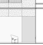
01 . SAND BLASTED CONCRETE BASE 02 . ARCHITECTURAL CMU 03 . INSULATED GLAZING 04 . ALUMINUM CURTAIN WALL SYSTEM 05 . ALUMINUM CLIP ON BOX FRAME SYSTEM 13 ALUMINUM VERTICAL CLIP ON FINS 14 METAL RAILING 15 METAL STAIR WITH SAND BLASTED CONCRETE TREADS 16 PAINTED GYP. BD 17 WOOD DOORS WITH METAL KEY NOTE:

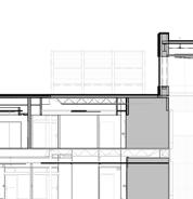
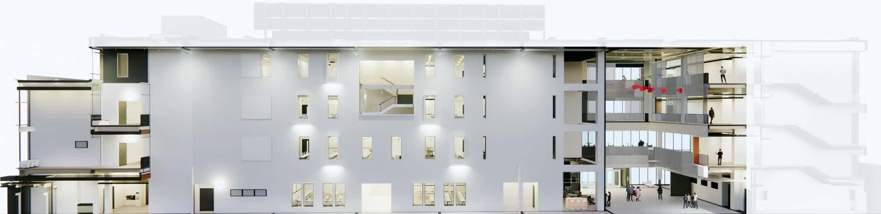
SCENESHOPROOF 14 15 16 17 13 12 11 ROOFT.O.S. 594'-6" 18 LIBRARY ARCHIVES READING ROOM & WORK AREA ARCHIVAL COLLECTIONS 2 A313 E-22E-04 E-03 E-06 MECH LOFT 3/8"13'6" LEVEL1 560'-0" LEVEL2 576'-6" ENTRYPLAZA 557'-0" ROOFT.O.S. 594'-6" EVENTSPACEROOF T.O.S. 581'-0" CA CF CH LOBBY UPPER LOBBY LOWER LOBBY CATWALK & GRID BLACK BOX THEATER PROMENADE ELEVATIONBEYOND VIEWATANGLE 3 A313 E-07E-02E-15 E-06E-04 E-26 CONTROL ROOM BLACK BOX SEATING STORAGE 13'6" 4'6" 16'6" 3'0" 37'6" DRESSING ROOM DRESSING ROOM FUNCTION E-17E-17 E-02E-16 ELECTRICAL DISEMBARKING AREA 20 21 22 ELEVATIONBEYOND VIEWATANGLE 23 E-19 MECH LOFT 1/16" = 1'-0" 1 SECTION -1 1/16" = 1'-0" 2 SECTION -2 E-03INSULATEDCEMENTBOARD,STRIATED E-04ALUMINUMCURTAINWALLSYSTEM E-06ROOFMONITOR E-07METALOVERHEADDOOR E-09ALUMINUMFRAMEDINSULATEDWINDOWS E-15METALSTAIRWITHSANDBLASTEDCONCRETETREADS E-16PAINTEDGYP.BD E-17WOODDOORSWITHMETALFRAME E-19INSULATEDCEMENTBOARD E-21ROOFTOPMECHANICALEQUIPMENT E-22BOOKSTACKS E-26BLACKBOXTENSIONGRID J J J J J J UP LEVEL1 560'-0" LEVEL2 576'-6" ENTRYPLAZA 557'-0" SCENESHOPROOF T.O.S. 581'-0" 14 15 16 17 13 12 11 ROOFT.O.S. 594'-6" 18 FLEX SPACE READING AREA LIBRARY LIBRARY ARCHIVES READING ROOM & WORK AREA ARCHIVAL COLLECTIONS INFORMATION DESK 2 A313 E-22E-04 E-03 E-06 MECH LOFT 11'8 3/8"13'6" 4'6" 16'6" 3'0" 37'6" LEVEL1 560'-0" 576'-6" ENTRYPLAZA 557'-0" LOBBY LOWER LOBBY BLACK BOX THEATER PROMENADE E-07E-02E-15 BLACK BOX SEATING STORAGE 16'6" 3'0" ROOFT.O.S. 594'6" 30 31 32 33 34 35 MECH.ROOF WELL ROOF BEYOND 37 38 CIRCULATION 36 1 A313 E-19E-19 E-21E-06E-09E-02E-09 2 A103 4 A313 2 A301 1 A301 A301 N 14 15 16 17 13 18 LS301 2 RECEPTION ELEVATIONBEYOND 2 A313 20 21 22 LOBBY EVENT SPACE ELEVATIONBEYOND VIEWATANGLE 23 E-19 MECH LOFT 1/16" = 1'-0" 3 SECTION -3 1/16" = 1'-0" 1 SECTION -1 J J J J J J UP LEVEL1 560'-0" LEVEL2 576'-6" ENTRYPLAZA 557'-0" SCENESHOPROOF T.O.S. 581'-0" ROOFT.O.S. 594'-6" FLEX SPACE READING AREA LIBRARY LIBRARY ARCHIVES READING ROOM & WORK AREA ARCHIVAL COLLECTIONS INFORMATION DESK 2 A313 E-22E-04 E-03 E-06 MECH LOFT 11'8 3/8"13'6" 4'6" 16'6" 3'0" 37'6" LOWER LOBBY E-07E-02E-15 BLACK BOX SEATING STORAGE LEVEL2 576'6" ROOFT.O.S. 594'-6" 30 31 32 33 34 35 MECH.ROOF WELL FACULTY COMMONS ATRIUM ADJUNCT FACULTY COMMONS ROOF BEYOND SHARED RESOURCE 37 38 CIRCULATION 36 BLACKBOXGRID 581'-8" 1 A313 E-19E-19 E-06E-09E-02E-09 E-26 E-21 2 A103 4 A313 12'10" 5'2" 16'6" 37'6" 2 A301 1 A301 3 A301 N 14 15 16 17 13 18 LS301 2 MEDIUM MEETING ROOM RECEPTION ADMIN ELEVATIONBEYOND 2 A313 LOBBY EVENT SPACE ELEVATIONBEYOND VIEWATANGLE E-19 MECH LOFT 1/16" = 1'-0" 3 SECTION -3 1/16" = 1'-0" 1 SECTION -1 ABCDEFGHJKLM 50'05'000000 25'1'1'1'1'12'4'3'1'2'1' 1/16"=1'-0"1/8"=1'-0"1/4"=1'-0"3/8"=1'-0"3/4"=1'-0"1"=1'-0"11/2"=1'-0"3"=1'-0" 8'
Adjacent to the site are existing warehouse buildings that were repurposed into university academic buildings several years ago; playing off this industrial warehouse context, exposed structure and natural light are used in lieu of expensive materials to create functional spaces supporting an array of activities.

The Event space accommodates 150 people in rows (15 sf / seat) or 90 people at tables (25 sf / seat). Could open up to lobby to increase capacity. Multi-use space for art exhibits, special events, receptions, meetings/ workshops, board meetings, lectures/presentations. Glazed wall overlooking Outdoor Reception Space / Living Room. Should be directly accessible to outdoor space. Acoustically separated from rest of building. Technology includes computer, projector and screen; a/v system; microphone/podium; handheld microphones. No permanent furniture. Conference Services sets the rooms with tables, chairs, etc. upon request.

Small gathering space for book readings. Movable partitions that allow space to be opened to combine with Display Space and Touchdown Space near entry. When there is no event, space serves as active reading area.


INTERIOR RENDERING
OUTDOOR GROUP STUDY SPACES
INTERIOR SMALL GROUP STUDY LIBRARY AND STUDY SPACES
COMMUNICATION ARTS & HUMANITIES
Studio Architect l Associate
BUILDING
KPNARCHITECTS, llc 2017 - Present
Brief Description of Project
Size : 199,670sf


Design Start : 2020
Constructions Start : 2022( est.)
Setting : Higher Education
The new CAH Building will be an integral part of the Bowie State experience, collecting and connecting students across various fields of study into a facility designed to inspire collaboration and student success. The new building will be the stage upon which students are empowered to speak and destined to soar, the primary vision for the project.

The building’s massing informs the approach to the facade design and materiality, responding to specific program needs, view opportunities, environmental orientation, and shaping a series of significant new campus spaces. The highly visual nature of the programs contained within the building are manifested in the design concept of “procession”. This concept guides the building siting, shape, placement, and materials.
Responsibility
Work closely with the team to identify FF&E needs and assist in developing detailed specifications for each FF&E item, including dimensions, materials, finishes, and other features. Assist the team in Revit modeling and produce construction drawings, including exterior wall sections, roof plans, and interior elevations.
SITE MAP VICINITY MAP LOCATION MAP 02
Bowie State University
Communication Arts and Humanities Building
UMCP Project #15‐669‐518‐00
100% Construction Documents
COLOR CODED DIAGRAMS


The following diagrams depict the spaces which are color coded by departmental. The organization is intended to create future flexibility as uses and departmental assignments change over the longer term, in addition to maximizing efficiency and shared use. The planning approach unites interior and exterior campus spaces to meet functional requirements and contribute to creating a dynamic campus character.


Bowie State University

Communication Arts and Humanities Building
UMCP Project #15‐669‐518‐00


100% Construction Documents

At Level 1, the northeast entry will be used most frequently by students arriving from campus and is adjacent to an existing parking lot.
LEVEL 1 - DEPARTMENTS
Levels 2 and 3 share a consistent organizational approach, with academic departments and learning resources located in the west wing and active learning classrooms in the east wing.
Level 2 – Departments

The upper levels of the ‘heart’ connect these areas and contain open and enclosed distributed informal learning spaces. History and Government and Communications faculty and administration space are at Level 2, with ROTC and Language, Literature and Cultural Studies at Level 3.
Level 3 – Departments
LEVEL 2 - DEPARTMENTS LEVEL 3 - DEPARTMENTS COMM COMM LLCS ROTC HGOV ROTC SUPPORT SUPPORT SUPPORT SHARED SHARED SHARED
MARK ISSUE DATE
s & H m a n t e B d g / B S U C A H A R C H 2 0 2 0


CONSTRUCTION
BUILDING UNDER CONSTRUCTION
The auditorium, at the south end of the building, is visible and accessible to both the campus and community. The three-story glass facades of the student entrance, at the north, connects the campus to the building providing visual connection as well as access, on the ground floor, to the centrally located courtyard. Enjoy a welcoming and engaging environment.
The 1500-seat auditorium is iconic anchor at the south end of the building adjacent to the Loop Road and MARC rail station. The facade of the auditorium continues the patterning and movement of the typical facade with adjustments in scale, scope, and openings.

CONSTRUCTION OF THE NEW CAH BUILDING

The new CAH Building will contain multiple departments and programs that are currently accommodated within the existing Martin King Jr. (MLK) Center which will be demolished once construction of the new building is complete. Project objectives include providing state-of-the art flexible and collaborative learning environments; specialized media production facilities, class laboratories, and departmental learning resources; faculty and administrative space to support interdisciplinary activity; and a 1500-seat assembly/auditorium space to serve a wide variety of BSU activities.
 CONSTRUCTION SITE PICTURE
CONSTRUCTION SITE PICTURE
CONSTRUCTION SITE PICTURE
PRINCE GEORGE’S COMMUNITY

COLLEGE MARLBORO HALL
Studio Architect l Associate
AND ADDITION
Brief Description of Project
Size : 130,156 SF
College Maryland. 20774.
Design Start : 2018
Constructions Start : 2020
Setting : Academic
Marlboro Hall, originally built in the 1970’s, is a three-story building that will end up being doubled in size once the project is complete. The project included a full existing conditions study of the whole building, finding deficiencies in the superstructure, roofing, exterior walls, stairs, and windows and doors.
MC459
KPNARCHITECTS, llc 2017 - Present
Department of General Services: ACTING SECRETARY: Atif T. Chaudhry
301 West Preston Street.
The renovations will provide the school with modern classrooms with new technology, more efficient MEP systems, and better accessibility measures. The 130,000 GSF renovated building will house laboratories for STEM departments, classrooms, offices, and study spaces. Additionally, work is being done to renovate several pedestrian bridges that connect Marlboro Hall to two other buildings on campus. Finally, the exterior of the building will be renovated and rebranded.
Responsibility
Understands the project and devises creative strategies to complete the work that meet or exceed the client’s expectations. Conducts research on existing building and campus infrastructure, coordinates field research, investigates and analyzes codes, produces site plans, floor plans, roof plans, demolition and phasing plans, and detailed elevations. Assists the Project Manager in providing overall architectural support throughout all phases of the project.
Baltimore. MD. 21201

George's
VICINITY MAP 03
MATERIAL AXON VIEWS
WALL ASSEMBLIES
Marlboro Hall Renovation & Addition


EXISTING: 40,056 GSF
NEW: 33,578 GSF EXISTING
Prince George's Community College 301 Largo Rd, Largo, MD 20774
DIAGRAMS - LEVELS 1,2,3,4
T: 301.546.6000
Rev 22 - 100% Construction Documents March 3, 2023 19. SUSTAINABILITY: A. SEE STRUCTURAL WINDOW GLAZING: 1. PROVIDE - IF LESS THAN -OR IF GLASS -OR IF TOP -OR IF AN 6. SEE CHAPTER IF A


Suite 414 Baltimore, MD 21230
T: 443.682.7757
Silman Associates 1053 31st. Street NW Washington, DC 20007 T: 202.333.6230
MEP/FP ENGINEERS:
Weigand Associates, Inc. 20270 Goldenrod Lane Germantown, Maryland 20876

T: 301.540.9060
SMOKE ANALYSIS:
Koffel Associates, Inc 8815 Centre Park Drive, Suite 200 Columbia, Maryland 21045
T: 410.750.2246
CIVIL GEOTECH ENGINEERS:
Triad Engineering, Inc. 1075 Sherman Avenue # D Hagerstown, Maryland 21740
T: 301.797.6400
LANDSCAPE ARCHITECTS:

Floura Teeter Landscape Architects, Inc. 800 N. Charles Street, Suite 300 Baltimore, Maryland 21201


T: 410.528.8395
ENVIRONMENTAL REMEDIATION:
Aerosol Monitoring & Analysis 1331 Ashton Road, Suite A Hanover, Maryland 21076 T410.684.3327
EXISTING: 34,086 GSF NEW: 27,961 GSF
EXISTING: 34,086 GSF NEW: 27,961 GSF
LEVEL 1 -CIRCULATION DIAGRAM 51 SF STOR. 154BA 6' 7' 11 3/4" PER PRINCE GEORGE'S COUNTY Circulation shall be counted for egress, not plumbing fixtures: Circulation 1st Floor ( Less 8'-0" width) = 8,807 SF 786 SF CLASSROOM BH203 546 SF CLASSROOM BH202 1" 8' 0" 1/8" 8' EXISTING


EXISTING: 37,014 GSF NEW: 29,230 GSF
EXISTING: 37,014 GSF NEW:
EXISTING NEW 1" = 80'-0" 2- LEVEL 02_ GSF Level 03_ GSF 1" = 80'-0" 4- Level 04_GSF 1" = 80'-0" 1- LEVEL 01_ GSF 6. SEE CHAPTER IF A ROOF 8. SKYLIGHT 2 19. SUSTAINABILITY: A. SEE STRUCTURAL WINDOW DESIGN. GLAZING: 1. PROVIDE SAFETY - IF LESS THAN 18" -OR IF GLASS IS LARGER -OR IF TOP EDGE IS -OR IF AN ADJACENT 6. SEE CHAPTER 11 IF A BUILDING 1. PROVIDE LEED 20. WINDOW EXISTING MARLBORO HALL PLUMBING FIXTURES WATER CLOSET -56 URINAL -38 LAVATORY -68 PRINCE GEORGE COUNTY-LARGO, SUBCONTRACTOR SHALL BE RESPONSIBLE THIS PROJECT AND SHALL PAY DIAGRAMS - LEVELS 1,2,3,4 LEVEL 1 -CIRCULATION DIAGRAM 51 SF STOR. 154BA 6' 0" 7' 11 3/4" PER PRINCE GEORGE'S COUNTY Circulation shall be counted for egress, not plumbing fixtures: Circulation 1st Floor Less 8'-0" width) = 8,807 SF 786 SF CLASSROOM BH203 546 SF CLASSROOM BH202 8' 6' 7/16" 8' 1/8" 8' 0" EXISTING
1. PROVIDE 20. WINDOW EXISTING MARLBORO HALL PLUMBING FIXTURES

A. SEE STRUCTURAL PROVIDE SAFETY -OR IF TOP EDGE -OR IF AN ADJACENT 6. SEE CHAPTER IF A BUILDING 1. PROVIDE LEED 20. WINDOW EXISTING MARLBORO HALL PLUMBING FIXTURES WATER CLOSET -56 PRINCE GEORGE COUNTY-LARGO, DIAGRAMS - LEVELS 1,2,3,4 LEVEL 1 -CIRCULATION DIAGRAM 51 SF STOR. 154BA 0" 7' 11 3/4" PER PRINCE GEORGE'S COUNTY Circulation shall be counted for egress, not plumbing fixtures: Circulation 1st Floor Less 8'-0" width) = 8,807 SF 786 SF CLASSROOM BH203 546 SF CLASSROOM BH202 8' 7/16" 8' 0" 8' 1/8" 0"
EXISTING NEW NEW
E J EQ
NEW:
EXISTING NEW 1" = 80'-0"
1" = 80'-0"
1" = 80'-0"
6. SEE CHAPTER IF A BUILDING ROOF 8. SKYLIGHT FRAMING EXISTING WATER URINAL LAVATORY ART DIAGRAMS - LEVELS 1,2,3,4 LEVEL 1 -CIRCULATION DIAGRAM LEVEL 2 -DIAGRAM 1341/2 671p BUSINESS FACULTY 171 86p PER PRINCE GEORGE'S COUNTY Circulation shall be counted for egress, not plumbing fixtures: Circulation 1st Floor Less 8'-0" width) = 8,807 SF 786 SF CLASSROOM BH203 546 SF CLASSROOM BH202 8' 1" 6' 5 7/16" 8' 0" 8' 1/8" 8' 0" PER PRINCE GEORGE'S COUNTY Circulation shall be counted for egress, not plumbing fixtures: Circulation 2nd Floor ( Less 8'-0" width) = 5,970 SF 8' 3/16" 8' 1/8"
NEW: 24,482 GSF
EXISTING: 40,056 GSF
33,578 GSF
2- LEVEL 02_ GSF 3- Level 03_ GSF
4- Level 04_GSF
1- LEVEL 01_ GSF
1" = 80'-0" 3- Level 1" = 80'-0" 4- Level 1" TERRA COTTA 5/8" AIR SPACE 4" POLY-ISO INSULATION AIR, VAPOR, WEATHER BARRIER 5/8" GYP. SHEATHING 6" METAL STUDS 5/8" GYP. WALLBOARD EXTERIOR SIDE 3/8" METAL PANEL 3/4" AIR SPACE 4" POLY-ISO INSULATION AIR, VAPOR, WEATHER BARRIER 5/8" GYP. SHEATHING 6" METAL STUDS 5/8" GYP. WALLBOARD EXTERIOR SIDE 4" BRICK 7/8" AIR SPACE 4" POLY-ISO INSULATION AIR, VAPOR, WEATHER BARRIER 5/8" GYP. SHEATHING 6" METAL STUDS 5/8" GYP. WALLBOARD EXTERIOR SIDE BRICK - WALL TYPE WALL ASSEMBLIES METAL PANEL - WALL TYPE TERRA COTTA - WALL TYPE CURTAINWALL - WALL TYPE STOREFRONT - WALL TYPE KAWNEER CLEARWALL, SEE SPEC EXTERIOR SIDE KAWNEER 451 UT OR 601 UT, SEE SPEC EXTERIOR SIDE REVISIONS: SCALE DRAWN ISSUE JOB STATE OF MARYLAND Professional Certification certify that the documents were prepared & approved by Gordon Thomas Ingerson, and am licensed Architect under the laws of the State Maryland. License 7313 Expiration Date: 10 /18 /2024 CONSULTANTS: OWNER: ARCHITECT OF RECORD: KPN Architects, LLC 1800 Washington Boulevard, Suite 414 Baltimore, MD 21230 T: 443.682.7757 3/5/2023 10:33:50 PM 1" 1'-0" Marlboro Hall Renovation & Addition Prince George's Community College 301 Largo Rd, Largo, MD 20774 301.546.6000 MATERIAL AXON VIEWS A-003 2112 Weigand Associates, Inc. 20270 Goldenrod Lane Germantown, Maryland 20876 T: 301.540.9060 Koffel Associates, Inc 8815 Centre Park Drive, Suite 200 Columbia, Maryland 21045 T: 410.750.2246 Triad Engineering, Inc. 1075 Sherman Avenue Hagerstown, Maryland 21740 T: 301.797.6400 Floura Teeter Landscape Architects, Inc. 800 N. Charles Street, Suite 300 Baltimore, Maryland 21201 T: 410.528.8395 Aerosol Monitoring Analysis 1331 Ashton Road, Suite Hanover, Maryland 21076 T410.684.3327 MEP/FP ENGINEERS: SMOKE ANALYSIS: CIVIL GEOTECH ENGINEERS: LANDSCAPE ARCHITECTS: ENVIRONMENTAL REMEDIATION: Author Silman Associates 1053 31st. Street NW Washington, DC 20007 T: 202.333.6230 STRUCTURAL ENGINEERS: Rev 22 - 100% Construction Documents March 3, 2023 1 AXON -Exterior Materials -SW 2 AXON -Exterior Materials -SE 4 AXON -Exterior Materials -NW 3 AXON -Exterior Materials -NE
1" TERRA COTTA 1 5/8" AIR SPACE 4" POLY-ISO INSULATION AIR, VAPOR, WEATHER BARRIER 5/8" GYP. SHEATHING 6" METAL STUDS 5/8" GYP. WALLBOARD EXTERIOR SIDE 1 3/8" METAL PANEL 3/4" AIR SPACE 4" POLY-ISO INSULATION AIR, VAPOR, WEATHER BARRIER 5/8" GYP. SHEATHING 6" METAL STUDS 5/8" GYP. WALLBOARD EXTERIOR SIDE 4" BRICK 1 7/8" AIR SPACE 4" POLY-ISO INSULATION AIR, VAPOR, WEATHER BARRIER 5/8" GYP. SHEATHING 6" METAL STUDS 5/8" GYP. WALLBOARD EXTERIOR SIDE BRICK - WALL TYPE 1
METAL PANEL - WALL TYPE 2 TERRA COTTA - WALL TYPE 3 CURTAINWALL - WALL TYPE 4 STOREFRONT - WALL TYPE 5 KAWNEER CLEARWALL, SEE SPEC EXTERIOR SIDE KAWNEER 451 UT OR 601 UT, SEE SPEC EXTERIOR SIDE CONSULTANTS: OWNER: ARCHITECT OF RECORD: KPN Architects, LLC 1800 Washington Boulevard,
STRUCTURAL ENGINEERS: 2 AXON -Exterior Materials -SE
NEW
EXISTING NEW NEW NEW: 24,482 GSF
29,230 GSF
34,086 GSF NEW: 27,961 GSF NEW EXISTING: 37,014 GSF NEW: 29,230 GSF EXISTING NEW NEW NEW: 24,482 GSF E J EQ EXISTING: 40,056 GSF NEW: 33,578 GSF EXISTING NEW 1" = 80'-0" 2- LEVEL 02_ GSF 1" = 80'-0" 3- Level 03_ GSF 1" = 80'-0" 4- Level 04_GSF 1" = 80'-0" 1- LEVEL 01_ GSF 6. SEE CHAPTER 11 IF A BUILDING ROOF AREA 8. SKYLIGHT FRAMING 3 2 LEVEL 01 GSF LEVEL 02 GSF LEVEL 03 GSF LEVEL 04 GSF
EXISTING: 40,056 GSF NEW: 33,578 GSF
EXISTING:
BUILDING ELEVATION & SECTION


BLDG. SECTION -NORTH SOUTH GRID X5 LOOKING WEST1
E-E SECTION NORTH SOUTH GRID X1 LOOKING EAST
LEVEL 2 156' -2" LEVEL 3 170' -2" LEVEL 4 184' -2" X-D X-G A-.3 EX. BH LEVEL 02 154' -8" EX. BH LEVEL 03 167' -6" EX. BH ROOF 179' -8" X-C X-B X-NN1 EX. BH LEVEL 01 140' -0" HIGH ROOF 198' -2" X-E X-F G.2 EXISTING V.I.F 12'-2 1/4" EXISTING V.I.F 12'-9 3/4" EXISTING V.I.F 14'-8" 2'-0" 1'-2" 13'-1" 35'-9" 40'-0" 32'-0" 32'-0" 38'-0" 30'-0" 2'-4" 18'-0" 52'-5" 5'-0" 21'-11" A-.5 G.4 LEVEL 1 140' -2" 14'-0" 14'-0" 14'-0" 16'-0" STUDENT LOUNGE ENTRY VEST CLASSROOM CLASSROOM STUDENT LOUNGE STUDENT LOUNGE H J H.4 3 A-233 2 A-235 4 A-230 X-A2 H.3 A-1 WEST ATRIUM SKYBRIDGE-WEST SKYBRIDGE WEST CLASSROOM CLASSROOM CLASSROOM CAMPUS CONF-SMALL 21'-0" BH BRIDGE G.8 G.5 2 A-230 12'-0" 10'-0" 2'-0" LEVEL 2 156' -2" LEVEL 2 156' -2" LEVEL 3 170' -2" LEVEL 3 170' -2" LEVEL 4 184' -2" LEVEL 4 184' -2" X-D X-G PENTHOUSE ROOF LEVEL 68' -5" PENTHOUSE ROOF LEVEL 68' -5" HIGH ROOF 198' -2" HIGH ROOF 198' -2" X-E X-F G.2 G.4 LEVEL 1 140' -2" LEVEL 1 140' -2" G.7 H J H.4 3 A-233 A-234 1 H.3 32'-0" 38'-0" 30'-0" 2'-4" 18'-0" 19'-11" 19'-5" 13'-1" 5'-0" 21'-11" CLASSROOM CLASSROOM CLASSROOM SOUTH CORRIDOR SOUTH CORRIDOR SOUTH CORRIDOR CLASSROOM CLASSROOM CLASSROOM MED. CLASSROOM SOUTH ATRIUM CLASSROOM COMMONS ADMIN. WORKROOM ADMIN FACULTY CORRIDOR ADMINADMIN WORKROOM OFFICE ADMIN WORKROOM ADMIN FACULTY CORRIDOR DEAN'S CONF. COMMONS COMMONS STAIR D 10'-5 1/2" 14'-0" 14'-0" 14'-0" G.8 G.5 15'-11 3/4" 1" A-295 1 3/5/2023 10:37:33 PM 1/16" = 1'-0"
1/16" = 1'-0" G-G 1/16" = 1'-0" F-F
LEVEL 2 156' -2" LEVEL 3 170' -2" LEVEL 4 184' -2" X-1 X-3 X-4 X-14 X-15 X-16 8.8 10.8 6.2 7.8 EXISTING ROOF 183' -10" EX. LH LEVEL 01 144' -2" EX. LH LEVEL 02 157' -5" EX. LH LEVEL 03 170' -8" 9.8 HIGH ROOF 198' -2" X-2 15.8 X-12 1.4 14.2 LEVEL 1 140' -2" 12.9 1 A-233 14'-0" 14'-0" 14'-0" 16'-0" V.I.F 13'-1 1/2" V.I.F 13'-3" V.I.F 13'-2 3/4" 5.1 1 A-230 2 A-234 1 A-234 3.2 4.1 6.8 1 A-235 3 A-236 5.5 LEVEL 2 156' -2" LEVEL 3 170' -2" LEVEL 4 184' -2" EX. BH LEVEL 02 154' -8" EX. BH LEVEL 03 167' -6" EX. BH ROOF 179' -8" EX. BH LEVEL 01 140' -0" HIGH ROOF 198' -2" LEVEL 1 140' -2" 0 1 10 20 STEAM ROOM -LEVEL 00 129' -2" 14'-0" 14'-0" 14'-0" 16'-0" V.I.F 10'-10 1/4" V.I.F 14'-8" V.I.F 12'-9 3/4" V.I.F 12'-2 1/4" 3 A-233 2 A-235 4 A-230 2 A-230 1 A-235 SIM. 2 A-230 SIM. 3 A-339 1 OVERALL EXTERIOR ELEVATION -SOUTH 1/16" = 1'-0" 2 OVERALL EXTERIOR ELEVATION -EAST LEVEL 2 156' -2" EX. LH LEVEL 01 144' -2" EX. LH LEVEL 02 157' -5" LEVEL 1 140' -2" 0 1 5 10 20 14'-0" 16'-0" V.I.F 13'-3" V.I.F 13'-2 3/4" 3 A-236 MATERIAL LEGEND BRICK - WALL TYPE 1 METAL PANEL - WALL TYPE 2 TERRA COTTA - WALL TYPE 3 CURTAINWALL - WALL TYPE 4 STOREFRONT - WALL TYPE 5 SUN SCREEN 3/5/2023 10:35:17 PM 1/16" = 1'-0" 1 OVERALL EXTERIOR ELEVATION -SOUTH X-14 X-15 X-16 8.8 10.8 7.8 EXISTING ROOF 183' -10" EX. LH LEVEL 01 144' -2" EX. LH LEVEL 02 157' -5" EX. LH LEVEL 03 170' -8" 9.8 15.8 X-12 14.2 12.9 5 10 20 V.I.F 13'-1 1/2" V.I.F 13'-3" V.I.F 13'-2 3/4" 1 A-230 2 A-234 1 A-234 6.8 EX. BH LEVEL 02 154' -8" EX. BH LEVEL 03 167' -6" EX. BH ROOF 179' -8" EX. BH LEVEL 01 140' -0" 5 10 20 STEAM ROOM -LEVEL 00 129' -2" V.I.F 10'-10 1/4" V.I.F 14'-8" V.I.F 12'-9 3/4" V.I.F 12'-2 1/4" 4 A-230 2 A-230 SIM. REVISIONS: SCALE DRAWN ISSUE JOB STATE OF MARYLAND Professional Certification certify that the documents were prepared & approved by Gordon Thomas Ingerson, and am a licensed Architect under the laws of the State of Maryland. License # 7313 Expiration Date: 10 /18 /2024 CONSULTANTS: ARCHITECT OF RECORD: KPN Architects, LLC 1800 Washington Boulevard, Suite 414 Baltimore, MD 21230 T: 443.682.7757 As indicated 2112 Weigand Associates, Inc. 20270 Goldenrod Lane Germantown, Maryland 20876 T: 301.540.9060 Koffel Associates, Inc 8815 Centre Park Drive, Suite 200 Columbia, Maryland 21045 T: 410.750.2246 Triad Engineering, Inc. 1075 Sherman Avenue # D Hagerstown, Maryland 21740 T: 301.797.6400 Floura Teeter Landscape Architects, Inc. 800 N. Charles Street, Suite 300 Baltimore, Maryland 21201 T: 410.528.8395 Aerosol Monitoring & Analysis 1331 Ashton Road, Suite A Hanover, Maryland 21076 T410.684.3327 MEP/FP ENGINEERS: SMOKE ANALYSIS: CIVIL GEOTECH ENGINEERS: LANDSCAPE ARCHITECTS: ENVIRONMENTAL REMEDIATION: KS Silman Associates 1053 31st. Street NW Washington, DC 20007 T: 202.333.6230 STRUCTURAL ENGINEERS: 1/16" = 1'-0" 1 OVERALL EXTERIOR ELEVATION -SOUTH 1/16" = 1'-0" 2 OVERALL
PARTIAL
EXTERIOR ELEVATION -EAST
SELF -ADHERING FLASHING AT


WALL SECTION @
ON COLD FORMED ANGLE OR BOXED STUD FRAMING


LEVEL 4 184' -2" 12.9
TO
A-245 1 3/4" /12 6" SEALANT
FOR
METAL
STEEL
ROD
SEALANT PVC ROOFING MEMBRANE FLASHING ON 5/8” THK PRESSURE TREATED PLYWOOD SHEATHING COLD FORM METAL FRAMING W/ INSULATION INFILL FOR COPING 1/2” PREFINISHED ALUMINUM COPING VAPOR RETARDER TURN UP ON PARAPET WALL SLOPE 1/4" /FT PVC ROOFING MEMBRANE CONTINUOUS BENT PLATE APPLIED FIREPROOFING STEEL BEAM 5/8" THK GYP BOARD SOFFIT PREFINISHED ALUMINUM WINDOW CEILING.REF: RCPS WINDOW TREATMENT ASSEMBLY MINERAL WOOL FIRE SAFING COLD FORMED METAL FRAMING MIN. 8" 24GA. COUNTER FLASHING RELIEVER SCREW FASTEN @ 12”O.C 4"
EXTRUDED ALUMINUM HEAD CLOSURE
TOP OF STUD 2'-8"
SELF-ADHERING SHEET AIR BARRIER WALL TYPE 1 SEE A-003
WALL ASSEMBLY
MASONRY TIES @ 16”O.C VERT. WEEP VENTS @ 24" O.C
ANGLE LINTEL
&
TO UNDERSIDE OF COPING .090 CLEAR ANOD .ALUMINUM CLOSURE WITH HEMMED EDGE SEAL TO ANGLE SELF -ADHERING STAINLESS STEEL FOR FLASHING SEAL AT EDGE WEEP VENTS @ 24" O.C COLD FORMED FRAMING STRAPPING TO SUPPORT EDGE OF GYP. BD., TYP. INSERT BATT INSUL. BETWEEN BEAM AND GYP. BD. AND APPLY SPRAY SEAL, TYP. 3/8" FIRE TREATED WOOD BLOCKING SUPPORTED
LEVEL 2 156' -2" X-1 EXISTING ROOF 183' -10" MASONRY INFILL DEFLECTION TRACK BEYOND 2'-11 3/8" 3'-0" A-245 3/4" /12 SELF -ADHERING FLASHING AT TO UNDERSIDE OF COPING 6" SEALANT SELF-ADHERING SHEET AIR BARRIER 1'-10" WALL TYPE 1 SEE A-003 FOR WALL ASSEMBLY BRICK MASONRY TIE WEEP VENTS @ 24" O.C .090 CLEAR ANOD .ALUMINUM CLOSURE WITH HEMMED EDGE SEAL TO ANGLE SELF -ADHERING STAINLESS STEEL FOR FLASHING SEAL AT EDGE ROD & SEALANT 5/8" THK GYP BOARD SOFFIT PREFINISHED ALUMINUM WINDOW STEEL JOIST WINDOW TREATMENT ASSEMBLY FIRE TREATED WOOD BLOCKING SUPPORTED ON COLD FORMED ANGLE OR BOXED STUD FRAMING 4" POLYISO
STEEL BEAM APPLIED FIREPROOFING CONTINUOUS BENT PLATE VAPOR RETARDER TURN UP ON PARAPET WALL SLOPE 1/4" /FT PVC ROOFING MEMBRANE VAPOR RETARDER PVC ROOFING MEMBRANE FLASHING ON 5/8” THK PRESSURE TREATED PLYWOOD SHEATHING SEALANT COLD FORM METAL FRAMING W/ INSULATION INFILL FOR COPING 1/2”
ALUMINUM COPING PRESSURE TREATED WD BLOCKING HOT AIR WELDED SEAM & CONT. SEALANT AT EDGE PVC ROOFING MEMBRANE STAINLESS STEEL COUNTER FLASHING RECIEVER SCREW FASTEN @ 12”O.C SEALANT STEEL SHELF ANGLE FIRE SAFING AT SLAB EDGE TYP. STEEL BEAM METAL OUTRIGGER 4" CMU DRAINAGE MAT THERMAL BREAK PAD 5/8”CEMENT BOARD SHEATHING ON PRESSURE TREATED WD. FRAMING SLOPE PREFINISHED METAL SILL .090 CLEAR ANOD .ALUMINUM CLOSURE WITH HEMMED EDGE SEAL TO ANGLE SEALANT WALL TYPE SEE A-003 FOR WALL ASSEMBLY FIREPROOFING 4" STEEL JOISTS METAL MASONRY TIES @16" O.C VERT WEEP VENTS @ 24" O.C COLD FORMED STRAPPING BATT INSULATION 3/8" STEEL ANGLE LINTEL COLD FORMED STRAPPING BATT INSULATION SS FLASHING LEVEL 4 184' -2" X-D EXISTING ROOF 183' -10" 3/4" /12 CONTINUE ROOFING MEMBRANE TO VAPOR RETARDER TURN UP ON PARAPET WALL SLOPE 1/4" /FT PVC ROOFING MEMBRANE VAPOR RETARDER PVC ROOFING MEMBRANE FLASHING ON 5/8” THK PRESSURE TREATED PLYWOOD SHEATHING SEALANT COLD FORM METAL FRAMING W/ INSULATION INFILL FOR COPING 1/2” PREFINISHED ALUMINUM COPING CONTINUOUS BENT PLATE 2" 24GA. COUNTER FLASHING RELIEVER SCREW FASTEN @ 12”O.C ANOD .ALUMINUM CLOSURE WITH HEMMED EDGE SEAL TO ANGLE SELF -ADHERING STAINLESS STEEL
INSULATION
PREFINISHED
12.9 18 18 18 HIGH ROOF 198' -2" J CEILING.REF: RCPS WALL TYPE 3, SEE A-003 FOR WALL ASSEMBLY PREFINISHED ALUMINUM SUN SCREEN W/ OUTRIGGER BOLTED TO BUILDING STRUCTURE 6" SEALANT SELF-ADHERING SHEET AIR BARRIER PREFINISHED ALUMINUM COPING COLD FORM METAL FRAMING W/ INSULATION INFILL FOR COPING 2 1/2” 4" 5/8”THK EXT.TRADE SHEATHING 7" THERMAL BREAK PAD APPLIED FIRE PROFING STEEL BEAM METAL OUTRIGGER VAPOR RETARDER TURN UP ON PARAPET WALL COLD FORMED METAL FRAMING CONTINUOUS BENT PLATE METAL VERTICAL SLIDE CLIP PVC ROOFING MEMBRANE FLASHING ON 5/8”THK PRESSURE TREATED PLYWOOD SHEATHING VAPOR RETARDER 24GA. COUNTER FLASHING RELIEVER SCREW FASTEN @ 12”O.C PVC ROOFING MEMBRANE 3/4" /12 SLOPE 1/4" /FT CONTINUE ROOFING MEMBRANE TO UNDERSIDE OF COPING MIN. 8" 2" THK. BOARD INSULATION 11' 4" AFF 1/2" THERMAL ISOLATION PAD FIRE TREATED WOOD BLOCKING SUPPORTED ON COLD FORMED ANGLE OR BOXED STUD FRAMING 1'-6" HIGH ROOF 198' -2" SEE A-003 FOR WALL ASSEMBLY PERIMETER FIRE CONTAINMENT ASSEMBLY W/ MOKE SEAL METAL VERTICAL SLIDE CLIP 5/8”THK EXT.TRADE SHEATHING SELF-ADHERING SHEET AIR BARRIER CONTINUE ROOFING MEMBRANE TO UNDERSIDE OF COPING PREFINISHED ALUMINUM COPING COLD FORM METAL FRAMING W/ INSULATION INFILL FOR COPING 2 1/2” PVC ROOFING MEMBRANE FLASHING ON 5/8”THK PRESSURE TREATED PLYWOOD SHEATHING VAPOR RETARDER 2" THK BOARD INSULATION PVC ROOFING MEMBRANE VAPOR RETARDER TURN UP ON PARAPET WALL MIN LAP AT TRANSITION SEAL ALL SEAMS PER MFR LEVEL 4 184' -2" EXISTING ROOF 183' -10" HIGH ROOF 198' -2" X-12 WALL TYPE 3, SEE A-003 FOR WALL ASSEMBLY A-245 2 CONC. SLAB APPLIED FIREPROFING METAL DECK ALUMINUM STOREFRONT APPLIED FIREPROFING STEEL BEAM PERIMETER FIRE CONTAINMENT ASSEMBLY W/ MOKE SEAL METAL VERTICAL SLIDE CLIP 5/8”THK EXT.TRADE SHEATHING SELF-ADHERING SHEET AIR BARRIER SEALANT 6" CONTINUOUS BENT PLATE CONTINUE ROOFING MEMBRANE TO UNDERSIDE OF COPING 3/4" /12 PREFINISHED ALUMINUM COPING COLD FORM METAL FRAMING W/ INSULATION INFILL FOR COPING 2 1/2” PVC ROOFING MEMBRANE FLASHING ON 5/8”THK PRESSURE TREATED PLYWOOD SHEATHING VAPOR RETARDER 2" THK BOARD INSULATION PVC ROOFING MEMBRANE SLOPE 1/4" /FT APPLIED FIREPROFING VAPOR RETARDER TURN UP ON PARAPET WALL VAPOR RETARDER MIN. 8" 24GA. COUNTER FLASHING RELIEVER SCREW FASTEN @ 12”O.C CEILING.REF: RCPS WINDOW TREATMENT ASSEMBLY FIRE TREATED WOOD BLOCKING SIM. SIM. 6"x3" HSS ACROSS VERTICAL HSS TUBES, SEE STRUCTURAL DETAIL 6/S-405 4"x4" HSS WITH 6" CFMF IN BETWEEN @ 16" OC. WALL SECTION @ J 18 18 18 18 18 18 LEVEL 2 156' -2" LEVEL 3 170' -2" LEVEL 4 184' -2" X-13 X-4 X-5 X-9 X-11 X-8 HIGH ROOF 198' -2" X-6 X-7 X-10 X-12 4.4 LEVEL 1 140' -2" 12.9 X-4B 3.1 A-339 2 SF-4 SF-4 14'-0" 14'-0" 14'-0" 16'-0" SF-4 SFA-332 2 A-333 1 LEVEL 2 156' -2" LEVEL 3 170' -2" LEVEL 4 184' -2" X-13 X-3 X-4 X-9 X-11 8.8 10.8 6.2 7.8 X-8 9.8 HIGH ROOF 198' -2" X-10 X-2 X-12 1.4 2.4 LEVEL 1 140' -2" 12.9 5.1 3.2 4.1 6.8 A-335 A-335 2 5.5 16'-0" 14'-0" 14'-0" 14'-0" SF-4 SF-4 A-331 3 A-335 6 A-334 1 A-335 1 10'-8" LEVEL 2 156' -2" LEVEL 3 170' -2" LEVEL 4 184' -2" X-D X-G X-C X-B HIGH ROOF 198' -2" X-E XD.5 X-F G.4 LEVEL 1 140' -2" G.7 H H.4 H.3 WELCOME FORUM VESTIBULE SF-4 SF-4 OPEN OFFICE CAFE A-332 1 14'-0" 14'-0" 14'-0" 16'-0" A-336 2 A-336 1 10'-7" X-D X-G X-C X-B X-A X-E X-F G.2 G.4 G.7 H H.4 H.3 G.8 G.5 A-337 1 1/16" = 1'-0" 1
WALL -SOUTH ATRIUM 1/16" = 1'-0" 2
WALL -SOUTH ATRIUM 1/16" = 1'-0" 3
WALL -WEST ATRIUM
NORTH
SOUTH
EAST

ATRIUM STEEL MESH PANEL


Different mesh types meet various requirements with regard to transparency and robustness.


The renovations will provide the school with modern classrooms with new technology, more efficient MEP systems, and better accessibility measures. The 130,000 GSF renovated building will house laboratories for STEM departments, classrooms, offices, and study spaces. Additionally, work is being done to renovate several pedestrian bridges that connect Marlboro Hall to two other buildings on campus. Finally, the exterior of the building will be renovated and rebranded.

LEVEL 2 156' -2" LEVEL 3 170' -2" 5 A-521 LEVEL 1 140' -2" OPEN 6'-6" 17'-3 3/4" 12'-1 1/4" OPEN 4’-0”W. STAINLESS STEEL MESH PANEL (McNICHOLS DESIGNER MESH 8150 AURA TYPE 304) 65% OPEN AREA 4’-0”W. STAINLESS STEEL MESH PANEL (McNICHOLS DESIGNER MESH 8150 AURA TYPE 304) 65% OPEN AREA STEEL MESH PANEL (McNICHOLS DESIGNER MESH 8150 AURA TYPE 304) 65% OPEN AREA GRAPHIC NUMBER PAINTED WHITE 4’-0”W. STAINLESS STEEL MESH PANEL (McNICHOLS DESIGNER MESH 8859 AURA TYPE 316) 77% OPEN AREA 7'-6" 6'-6" 14'-0" 4’-0”W. STAINLESS STEEL MESH PANEL (McNICHOLS DESIGNER MESH 8859 AURA TYPE 316) 77% OPEN AREA PAINTSTEEL FRAMING ACCENT COLOR STOREFRONT DOOR FRAME 4’-0”W. STAINLESS STEEL MESH PANEL (McNICHOLS DESIGNER MESH 8150 AURA TYPE 304) 65% OPEN AREA 4’-0”W. STAINLESS STEEL MESH PANEL A-338 LEVEL 2 156' -2" 3'-6" 3'-0" HAND RAIL 1"⌀ SS NUT W/ SS 2"⌀ WASHER 4" x 4" PAINTED ACCENT COLOR STEEL FRAMING PAINTED STEEL CLIP 1/4" ⌀ PAINTED STEEL HAND RAIL PAINTED STRUCTURE ACCENT COLOR CONC. SLAB SCHEDULED FLOORING ACCENT COLOR 1/8" GAP 1"⌀ STEEL SPACER 1/2" 2" 3/8" 3" 4’-0”W. STAINLESS STEEL MESH PANEL (McNICHOLS DESIGNER MESH 8859 AURA TYPE 316) 77% OPEN AREA 7" 1/8" GAP BETWEEN PANEL PAINTED STEEL CLIP 1/4" 1" W/ SS 2" 4" 4’-0”W. STAINLESS STEEL MESH PANEL (McNICHOLS DESIGNER MESH 8150 AURA TYPE 304) 65% OPEN AREA 2" SUPPORT 4" STEEL 3/6/2023 6:54:47 PM 1/4" = 1'-0" 1 ELEVATION -SOUTH ATRIUM BRIDGE 1/4" = 1'-0" 2 SECTION -SOUTH ATRIUM BRIDGE ELEVATION -WEST ATRIUM BRIDGE 1/32" = 1'-0" 9 BRIDGE -KEY PLAN 4 SECTION -WEST ATRIUM BRIDGE 1 1/2" = 1'-0" 5 SECTION DETAIL BRIDGE RAILING 1 1/2" = 1'-0" 6 PART ELEVATION BRIDGE RAILING 6" = 1'-0" 7 ELEVATION DETAIL METAL MESH PANEL LEVEL2 156-2 LEVEL3 170-2 LEVEL4 184-2 HGHROOF 198-2 LEVEL1 140-2 1 4" = 1 -0" 1 WELCOME FORUM EAST FACING ELEVATION 1 4 = 1 2 WELC KEYNOTES
4’ W. FRAMELESS SS STEEL MESH PANEL (McNICHOLS 8859 AURA TYPE 316)77% OPEN AREA
AREA
4’ W. FRAMELESS SS STEEL MESH PANEL (McNICHOLS 8150 AURA TYPE 304)65% OPEN

DN FD DN UP FD A-201 2 A-200 1 X-D X-D X-G X-G X-13 X-1 X-1 A-.3 A-.3 X-C X-C X-B X-B X-3 X-3 X-4 X-4 X-5 X-9 X-11 X-14 X-14 X-15 X-16 EXISTING BLADEN HALL EXISTING LANHAM HALL EXISTING CHESAPEAKE HALL 8.8 10.8 6.2 7.8 X-8 9.8 30'-0" 38'-0" 32'-0" 32'-0" 40'-0" 32'-0" 3'-9" 13'-1" 1'-2" EXISTING CENTER FOR PERFORMING ARTS MAIN ENTRY OPEN TO ABOVE X-A X-A X-E X-E X-6 X-7 OPEN TO ABOVE X-10 XD.5 X-F X-F X-2 X-2 CLASSROOM 153 MAIN MECH 161 SCULPTURE STUDIO 124 CERAMIC STUDIO 123 SIDE GALLERY 120D ART GALLERY 120 ELEC 122 EAST VEST. 103A QUAD VEST 104A MEN 151 WOMEN 150 FIRE PUMP 155BB LARGE CLASSROOM 154C 15.8 CH-0.1 CH-1 16'-10" 40'-0" 32'-0" 3'-9" OUTDOOR ART YARD X100 X-12 X-12 SOUTH ATRIUM 103 4'-6" 43'-6" 30'-4 3/4" 9'-7 1/4" 21'-11" 5'-0" 13'-1" 11'-11" 7'-6" 12'-5" 7'-6" 18'-0" 2'-4" 6'-6" 17'-6" 13'-8" 10'-4" 3'-11" 20'-1" 9'-9" 14'-7" 13'-10" 13'-10" 18'-2" 9'-10" 28'-0" 28'-0" 28'-0" 28'-0" 23'-8" 24'-4" G.2 G.2 A-201 1 UTILITY X103 A-200 2 1.4 WEST ATRIUM 101 FACULTY OFFICE 140C CHAIR OFFICE 140B ELEC 142B FACULTY OFFICE 142A FACULTY OFFICE 143M FACULTY OFFICE 143C IDF 143B FACULTY OFFICE 143D FACULTY OFFICE 143F FACULTY OFFICE 143H FACULTY OFFICE 143G COMMONS 141 FACULTY OFFICE 142C FACULTY OFFICE 142D FACULTY OFFICE 143L FACULTY OFFICE 143K FACULTY OFFICE 142F STOR. 154BA CLASSROOM CORRIDOR 154 LARGE CLASSROOM 154B FACULTY OFFICE 142E ELEV E-3-2 FACULTY OFFICE 143E MEN 130 STORAGE 126 ELEV E-2-1 JAN 128 STORAGE 162 FACULTY EAST 143 STOR 124F WELDING 124B ELEV EL-1-1 STAFF TOILET 140P STAFF TOILET 143A 40'-0" 11'-11" 7'-6" 12'-5" 7'-6" 18'-0" 2'-4" 14'-3 7/8" 15'-8 1/8" 1'-1 7/8" 8'-6 1/8" 6'-4" 22'-0" 11'-0" 21'-0" CORR 155 TRASH & RECYCLE 155BA MDF 155C JAN 155A STORAGE 141D FACULTY CORRIDOR 140 A-.5 A-.5 1'-2" 14.2 STAIR ST-C-1 WELCOME FORUM 152 TUTORING 141B FACULTY WEST 142 ADMIN. WORKROOM 140G UTILITY X102 CATERING PANTRY 120B X-E2 X-E3 4.4 X-3A 2.4 G.4 G.4 G.3.5 G.3 TUTORING 141A GALLERY STORAGE 121 IDF 127 CURATOR 120A WELCOME FORUM 100B CONSULT 152A CONSULT 152B CONSULT 152C KILN 123C GLAZE ROOM 123B GALLERY VEST. 120E CLAY MIX 123D UP T-1 9X9 - 9x9 GENERATOR (17 5 X 6 5) SW CH5X10 FACULTY OFFICE 140D PANTRY BREAK 140E AVP OFFICE 140JA ADMIN 140Q STAIR ST-D-1 MED. CLASSROOM 154A 12.9 ADJ-FACULTY OFFICE 141E TUTORING III 141F X-4B G.7 G.7 X-2A DUST COLLECTOR 124D UP MATCHLINE 5.1 WOMEN 129 H H J J 3.1 H.4 TUTORING 141G 0.3 0.7 F.1 SUPERVISOR OFFICE 171 SUPERVISOR OFFICE 172 DIRECTOR OFFICE 173 LOCKER ROOM 170B TUTORING 141C CERAMICS SHELL 124A AIR COMPRESSOR 124E STOR 125A FORUM OFFICE 100C MED. CLASSROOM 154D ELEC 155D ENTRY VEST 100A SPRAY BOOTH 123A OUTDOOR STORAGE X100B STAIR ST-E-1 VEST. 102A EAST ALCOVE 160 EAST CORRIDOR 104 3.2 4.1 6.8 X-Q GENERATOR YARD X101 X-A2 X-A2 H.3 490 1/2 4211 1 / 4 NORTH CORRIDOR 102C A-1 A-1 24'-0" 24'-0" 24'-0" 24'-0" 24'-0" 24'-0" 24'-0" 24'-0" 24'-0" 24'-0" 12'-0" 12'-0" 12'-0" 6'-11" 5'-1" 6'-5" 9'-7" 8'-0" AS-100 0.2 1 A111A 1 A-111A 1 A-111D 1 A-111D 1 A-111D / 1 A111B 1 A-111B 1 A-111C 1 A111C A-111E A-111E 1 A111D VEST. B100 OUTDOOR STORAGE X100A G.8 G.8 G.5 G.5 MAIN ELEC 110 OFFICE 173A DSS TESTING 173B GALLERY 100D MAIN LOBBY 100 STORAGE 155B PROFESSIONAL TESTING ROOM 170H PROFESSIONAL TESTING ROOM 170G PROCTOR 170F BREAKROOM 175 STAIR ST-A-1 SIM. SIM. SIM. GROUP TESTING ROOM 170A INTAKE ROOM 170C ACA PLACEMENT TESTING 170 STUDENT SEATING 104B STORAGE 143J GALLERY TOOLS 120C MATERIAL STORAGE 125D PLASTER MIX 125E SHELL SPACE 100E SECURITY /INFO DESK 102B 3D-BASIC LAB ARCHITECTURE MODEL STUDIO 125 MICRO-EQUIP. WOODWORKING SHOP 125C WOODWORKING 124C VP WAITING 140J JAN 100D-A MAIL/COPY ROOM 140F MAIL/COPY ROOM 140H WORK STATIONS 170E 5.5 EMER ELEC 110A INTAKE ROOM 170D 1'-7 5/8" 8'-4" 1'-6 3/8" CMU KNOCK OUT FOR FUTURE OPENING MONITORING 174 AVP ASTNT OFFICE 140JB EXEC. VP OFFICE 140JC EXEC. VP /PROVOST OFFICE 140JD A-382 3 1. SLAB ELEVATIONS AND FLOOR TO FLOOR HEIGHTS ARE BASED ON EXISTING CONDITIONS SURVEY INTENT OF DRAWINGS IS FOR SLABS AT NEW AREAS TO ALIGN WITH EXISTING CONSTRUCTION. CONTRACTOR TO VERIFY ALL EXISTING SLAB ELEVATIONS AND NOTIFY ARCHITECT OF ANY VARIANCE. 2. ALL MARKERBOARDS TO BE CENTERED ON WALLS UNLESS NOTED OTHERWISE. REFER TO -002 FOR ADDITIONAL INFORMATION. 3. REFER TO FURNITURE PLANS (A-800s) FOR FRONT OF CLASSROOM ORIENTATION. GENERAL PLAN LEGEND: ADA OPERATOR - REF TO TYPICAL MOUNTING HEIGHTS FLOOR BOXES/POKE THROUGH, REF TO ELECTRICAL DWGS WALL MOUNTED DISPLAY - REF TO MEP DWGS FIRE EXTINGUISHER CABINET HYDRATION STATION - REFER PLUMBING FIXTURE SCHEDULE. ELECTRIC WATER COOLER - REFER PLUMBING FIXTURE SCHEDULE. REFRIGERATOR - REFER FFE PACKAGE. DISHWASHER - REFER FFE PACKAGE. MICROWAVE - REFER FFE PACKAGE. MONITOR FEC HC DF REF DW MW LEVEL 1 OVERALL PLAN REVISIONS: SCALE DRAWN ISSUE JOB STATE OF MARYLAND Professional Certification certify that the documents were prepared & approv by Gordon Thomas Ingerson, and am a licensed Architect under the laws of the State of Maryland. License # 7313 Expiration Date: 10 /18 /2024 CONSULTANTS: OWNER: ARCHITECT OF RECORD: KPN Architects, LLC 1800 Washington Boulevard, Suite 414 Baltimore, MD 21230 T: 443.682.7757 10:34:53 AM As indicated Renovation & Addition Prince George's Community College 301 Largo Rd, Largo, MD 20774 T: 301.546.6000 LEVEL 1 OVERALL FLOOR PLAN A 101 2112 Weigand Associates, Inc. 20270 Goldenrod Lane Germantown, Maryland 20876 T: 301.540.9060 Koffel Associates, Inc 8815 Centre Park Drive, Suite 200 Columbia, Maryland 21045 T: 410.750.2246 Triad Engineering, Inc. 1075 Sherman Avenue D Hagerstown, Maryland 21740 T: 301.797.6400 Floura Teeter Landscape Architects, Inc. 800 N. Charles Street, Suite 300 Baltimore, Maryland 21201 T: 410.528.8395 Aerosol Monitoring & Analysis 1331 Ashton Road, Suite A Hanover, Maryland 21076 T410.684.3327 MEP/FP ENGINEERS: SMOKE ANALYSIS: CIVIL GEOTECH ENGINEERS: LANDSCAPE ARCHITECTS: ENVIRONMENTAL REMEDIATION: DK Silman Associates 1053 31st. Street NW Washington, DC 20007 T: 202.333.6230 STRUCTURAL ENGINEERS: Rev 22 - 100% Construction Documents March 3, 2023 N 18 181/26/2023Rev 18 Exterior Details
ATRIUM 3D RENDERING
Marlboro Hall will be designed to support and house the below programs, spaces, and occupants as shown:

Table E.1-1: Floor Programming
Visual Arts Instruction (Classrooms/Labs)
Marlboro Hall Art Gallery
Art & Philosophy (Offices)
1st Floor
Veterans Services, PGCC Cares, Counseling Services (Offices and Supporting Spaces)
Weekend Office
Study Lounge and Study Space
English/History/Political Science/Geography/Anthropology Instruction (Classrooms/Labs)
Learning Foundations Learning Center & Labs
2nd Floor
Individual Study/Group Study Rooms
Conference Rooms
Non-assignable Lounge/Study Space
Mathematics, Teacher Education, Psychological/Sociological Instruction (Classrooms/Labs)
Mathematics Learning Center
3rd Floor
Individual Study/Group Study Rooms
Non-assignable Lounge/Study Space
Mathematics, Learning Foundations, Liberal Arts (excluding Art and Philosophy), and Social Sciences and Business (Offices)
4th Floor
Faculty Lounge/Professional Development Training Room
Conference Room
Marlboro Hall Renovation and Addition Part I and II Program Page 122
CONSTRUCTION
BUILDING UNDER CONSTRUCTION
Renovate 77,672 NASF of space in Marlboro Hall and add an additional 72,719 NASF of space. The proposed solution will replace deteriorated building infrastructure components, correct extensive ADA issues, modernize finishes and equipment, and provide for expanded academic instruction in divisions such as Learning Foundations, Liberal Arts, Social Sciences and Business and STEM. Transforming the outdated and undersized Marlboro Hall building to a modern instructional classroom and lab building will create a synergy for students and faculty currently missing in the current building.

BUILDING UNDER CONSTRUCTION


KPN was Architect of Record and Prime Consultant for the project. Our scope included researching the existing building and campus infrastructure, field research, code analysis, and production of demolition and phasing plans and specifications. KPN conducted extensive document reviews and interviews of College personnel to ensure that the demolition documents were based on the best possible information. Laser scanning was conducted to produce a point cloud model of the existing building, including MEP services, and a utility locator was contracted to locate utilities for which there was insufficient documentation. A complete team of consultants was utilized to investigate the existing conditions and produce the demolition documentation, including in addition to the above an envelope consultant, a hazmat consultant, civil engineer, structural engineer, MEP engineer, and geotechnical consultant.
 CONSTRUCTION SITE PICTURE
EXISTING BUILDING
PICTURE OF BEAM SIGNING CEREMONY
RASH FIELD REDEVELOPMENT
Studio Architect l Associate
KPN ARCHITECTS, llc 2017 - Present
Brief Description of Project
Size : 7.5 Acres
Design Start : 2017
Constructions Start : 2021( est.)
Setting : Religious
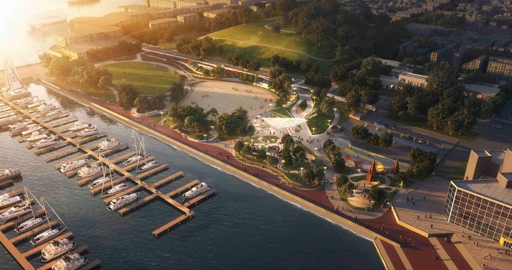
The redevelopment of Rash Field, located adjacent to Baltimore’s Inner Harbor,is expected to draw more visitors to the area and generate revenue for the city. The rejuvenated park will enhance recreation options for users, create a gateway to the waterfront promenade from the surrounding neighborhood, and contribute to the broader vision for the Inner Harbor.

KPN is the Architect of Record working with a site designer, Mahan Rykiel Associates, for the overall park.
KPN’s responsibility includes the architectural work associated with the park improvements, incorporating a retail pavilion and public facilities inserted into the landscape with a green roof wrapping over the top of the structure.
Responsibility
Responsible for architectural documentation, Revit modeling and coordination with consultants, and complete CA services.
04
CONSTRUCTION DOCUMENTS
Based on the approved Design Development documents, I assisted the project manager in preparing Construction Documents consisting of drawings and specifications that described the scope of construction work. These documents were suitable for filing with the Building Department and for use in construction by a qualified General Contractor.
Rash Field Baltimore, Maryland
EGRESS LOAD AND CALCULATIONS AREA A: 80TOTALOCCUPANTSNONSEPARATEDMIXEDUSE,USE GROUPSA-2 1,197TOTALGSF CAFE 1,197NSF/15NSFPEROCC.=80OCCUPANTS
AREA B:
13TOTALOCCUPANTSNONSEPARATEDMIXEDUSE,USE
GROUPSA-5,S-1(ACCESSORY)
682TOTALGSF
MEN PUBLIC TOILET
260GSF/50GSFPEROCC.=6OCCUPANTS
WOMEN PUBLIC TOILET
241GSF/50GSFPEROCC.=5OCCUPANTS
JAN.
68GSF/300GSFPEROCC.=1OCCUPANT
ELEC. ROOM
113GSF/300GSFPEROCC.=1OCCUPANT
NY 10001 t: 212.924.4050
Structural Engineer (Shade Feature) SIMPSON GUMPERTZ & HEGER 135 SOUTH LaSALLE STREET, SUITE 3800 CHICAGO, IL 60603 t: 312.754.7500
Structural Engineer (Site + Pavilion) ALBRECHT ENGINEERING, INC. 3500 BOSTON STREET, SUITE 329, MS-12 BALTIMORE, MD 21224 t: 410.522.5870
Park Design GRINDLINE SKATEPARKS,
72RECESSEDFIREEXTINGUISHERCABINET.REFER TOLS0.02DRAWINGFORLOCATION.
74SEMI-RECESSEDFIREEXTINGUISHERCABINET. REFERTOLS0.02DRAWINGFORLOCATION.
6&$/( 6287+($67 $;21 6&$/( 1 257+($67 $;21 13 12 11 10 13 12 11 10& 8 U+ / WS' 5 ) LG $ K BF BG 6 A6.02 %(/2: %(/2: A6.02 $ $ 2020-2300 1/13/2021 PAGE: 32 of 151. (E) (E) (E) (E) (E) 21 A B C 3 A.1 50GSF 244SF WOMEN 50GSF 261SF MEN 300 GSF 69SF JAN. 40 8.8" 36" 40 8.8" 36" 7 1.5" 634" 1.3" 34" 56 1 4610 EXIT EXIT FUTURE B.O.H PANTRY 102 FUTURE MECH. ROOM 103 15GSF 1,197SF CAFE 80OL 300 GSF 113SF ELEC. ROOM 1OL 1 80 7272 74 NSF LINE TYPE EXITING SYMBOLS =EXITTOEXTERIOR =EXITFROMASPACE =EXITFROMSTORY (E)=ExistingConstruction EGRESS COMPONENT CAPACITY SYMBOLS NUMBEROF CALCULATEDOCCUPANTSEXITING EXIT WIDTHREQUIRED (IN.)EXITWIDTH PROVIDED(IN.) NUMBEROF OCCUPANTSEXITING STAIRNAMEOR DESCRIPTION 33" 145 29" 48" 145 43.5" STAIR#1 USEGROUPOFSPACE AREAOFSPACE SFPEROCCUPANT (E)=ExistingConstruction (E)=ExistingConstruction 0OCCUPANTLOAD OFSPACE ASSEMBLY OCCUPANCY SYMBOLS 300 GSF 000SF USE GROUP CALCULATEDEXIT WIDTHREQUIRED (IN.) EXITWIDTH PROVIDED(IN.) =DIVISIONBETWEEN CALCULATED OCCUPANTLOAD AREAS
LIFE SAFETY TAG
FOR SEAL
ISSUED
Owner WATERFRONT PARTNERSHIP of BALTIMORE 650 S. EXETER STREET, SUITE 200 BALTIMORE,
t.443.743.3308 Architect (Design) GENSLER
t.410.539.8776 Architect
Record) KPN
t.443.682.7758 Civil
t.800.787.3755
C.C. JOHNSON & MALHOTRA, P.C. (CCJM) 400 EAST PRATT STREET, SUITE 604, BALTIMORE, MD 21202 t.410.461.9920 Landscape Architect MAHAN RYKIEL ASSOCIATES 3300 CLIPPER MILL ROAD, SUITE 200 BALTIMORE, MD 21211 t.410.235.6001 Lighting Design BRANDSTON PARTNERSHIP, INC. 302 FIFTH AVENUE, 12th FLOOR NEW YORK,
MD 21202
1 EAST PRATT STREET, SUITE 202 BALTIMORE, MD 21202
(of
ARCHITECTS 1800 WASHINGTON BOULEVARD, SUITE 441 BALTIMORE, MD 21230
Engineer RK&K 700 EAST PRATT STREET, SUITE 500 BALTIMORE, MD 21202
M.E.P.
Skate
INC. 4619 14th AVENUE SW SEATTLE, WA 98106 t: 206.932.6414 Playgrounds NATURAL LEARNING INITIATIVE 2230 STINSON DR. RALEIGH, NC 27607 t: 919.515.8345 Signage YOUNTS DESIGN, INC. 3600 CLIPPER MILL ROAD, SUITE 410 BALTIMORE, MD 21211 t: 443.825.4100
A BLDG. PERMIT SUBMISSION 11 01/2019 BLDG. PERMIT RE-SUBMIT 11 06/2020 DATE 2 A3.01 3 A3.01 1 2 2 A4.03 CAFE MEN WOMEN B.O.H PANTRY (FUTURE) 1" REVEAL 1" REVEAL 10 9 8 7 6 5 4 3 2 1 A B C D E F 0 A A 2020-2300 6&$/( 6287+($67 $;21 6&$/( 1 257+($67 $;21 13 12 10 4 3 2 13 12 10 5 4 3 2 X 3 0 & 8 U+ 3 WS' 5 K ) LG $ K BF BG N A6.02 %(/2: %(/2: A6.02 $ $ 2020-2300 1/13/2021 PAGE: 32 of 151.
NORTHEAST AXON
BUILDING SECTION FLOOR PLAN
SOUTHEAST AXON
2 A3.01 3 A3.01 1 2 2 A4.03 CAFE MEN WOMEN B.O.H PANTRY (FUTURE) 1" REVEAL 1" REVEAL 10 9 8 7 6 5 4 3 2 1 A B C D E A 2020-2300
VISIT THE PROJECT SITE

Attend project coordination meetings, visit the project site at biweekly intervals when work relevant to our scope is underway as appropriate to monitor the progress of the work and determine whether the work is in accordance with the Construction Documents. contribute to the broader vision for the Inner Harbor.

GENERAL NOTES
Rash Field Baltimore, Maryland
FIELD LEVEL 11'STAINLESS STEEL FRAMED WIRE NET RAILING SYSTEM. RAILING POST SECURED TO CONCRETE SLAB 1" DRAINAGE PANEL ON 7" RIGID INSUL. OVER 3/8" DRAINAGE PANEL ROOT R R PROTECTION BOARD, AND FLUID WATER PROOFING SYSTEM 12" CONCRETE SLAB ALUMINIUM CURTAIN WALL SYSTEM CONCRETE PAVEMENT & GRADED STONE BASE SEE LANDSCAPE CIVIL DRAWINGS 4" PERF. DRAIN WRAPPED WITH/ GEOTEXTILE FABRIC GRADED STONE DRAINAGE MATERIAL CONCRETE FOOTING - E S TU DRAWINGS BACK FACE OF CURTAIN WALL INSULATION AND DAMPPROOFING 4" DRAINAGE FILL AND 8" CRUSHED STONE BACKFILL CONCRETE SLAB ON GRADE VAPOR R ¾SPACE BETWEEN BACK OF MULLION STEEL TUBE 2" 4" VERT. STL. TUBE @ EA. VERT. MULLION OVERLOOK SLAB FOLD LINE 22' - 1/2" 8" 2'6" MIN. 1/2" EARTH COVER - E LANDSCAPE CIVIL DRAWINGS 5" 12" TOP OF CURB T/SLAB A6.21 A6.21 COATS SYNAVAX ENERGY PROTECT ON CONCRETE SOFFIT AND CURB1" CONTINUOUS REVEAL SEALANT STAINLESS STEEL FLASHING CONCRETE COLUMN BEYOND 3" 5" EXTRUDED ALUM. HEATER ENCLOSURE FINISHED TO MATCH R NWA (BY FUTURE TENANT) sim A6.03 sim A6.02 R N A CLIPS TO EITHER SIDE OF STEEL TUBE CEILING BEYOND (EXPOSED CONCRETE) REFER FINISH PLAN FOR SCHEDULED FLOOR FINISH CAFE 3" WATERSTOP-REFER STRUCTURAL 2' - 0" FIELD LEVEL 11'A FACE OF CURTAIN WALL CURTAIN WALL BEYOND (SLAB SLOPES UP) 1REVEAL, CONTINUOUS ALUMINUM INSULATED R N A SYSTEM BEYOND CONCRETE WALL 1/2" JT. FILLER SEALANT PAVEMENT BASE E LANDSCAPE CIVIL DRAWINGS GRADED STONE DRAINAGE MATERIAL CONCRETE FOOTING E R R DRAWINGS 3" RIGID INSULATION 4" DRAINAGE FILL AND 8" CRUSHED STONE BACKFILL SEALANT Y BD. ON 3" RIGID INSULATION ZFURRING SEALANT SEE LANDSCAPE CIVIL FOR EARTH OVER WP SYSTEM 1" DRAINAGE PANEL OVER 7" RIGID INSUL. ON 3/8" DRAINAGE PANEL OVER ROOT AR E PROTECTION BOARD, AND FLUID WATER PROOFING SYSTEM OVERLOOK SLAB FOLD LINE 22' - 1/2" 6" PERF. DRAIN WRAPPED WITH/ GEOTEXTILE FABRIC CONCRETE SLAB ON GRADE VAPOR RE E 12" CONCRETE SLAB T/SLAB T/SLAB A6.03 A6.02 COATS SYNAVAX ENERGY PROTECT ON CONCRETE SOFFIT AND CURB STAINLESS STEEL FRAMED WIRE NET RAILING SYSTEM. RAILING POST SECURED TO CONCRETE SLAB 1" 1" CONTINUOUS REVEAL SCHEDULED BASE WOMEN CEILING MOUNTED LIGHT FIXTURE REFER FINISH PLAN FOR SCHEDULED FLOOR FINISH CW3SEE S T R U C T U R A L - DRAWINGS WATERSTOP-REFER STRUCTURAL THERMOSTAT WITH GUARD -REFER MECHANICAL DAMPPROOFING PROJECT NO. DRAWN BY REVIEWED BY SCALE 15 14 13 12 11 10 ISSUED FOR DATE 15076 As Noted AB, EA, CM, OC GTI, RL SHEET NOTES GENERAL KEY PLAN C U \Docume nts\Ras Field Ar _200930 k .rvt A4.02 WALL SECTIONS S 3/4" 1'-0" CURTAIN WALL SECTION 2 E 3/4" 1'-0" WALL OFF WOMEN RR SECTION 1 LATEST AUTHORITIES, VERIFIED, CONDITIONS, IMMEDIATELY REPORTED PROCEEDING WORK. AND AVOID DUST. CONSTRUCTION REQUIRED AIR W PERMITS HAVING THIS POSTED SPECIFICALLY METHODS DATA AS W SYSTEM SHOWN TERMINATIONS WITH SHOWING FASTENERS ALL ACCORDANCE PUBLISHED BE BUILDING INTERIOR FIXTURES BEFORE WORK TO COMMENCE UNTIL ALL SUBMITTALS ARE APPROVED. R TO SHEET A1.30 FINISH MATERIALS FOR MATERIAL CODES AND BASIS OF DESIGN INFORMATION. RT N OF FORMED A TU CONCRETE WALLS THAT ARE VISIBLE TO PUBLIC OR INTERIOR SPACES SHALL ADHERE TO ACI STANDARD 347.3R-13 LEVEL CSC3 FOR FORMED CONCRETE SURFACES. R TO LIGHTING DESIGN DWGS FOR ALL LIGHTING FIXTURES. CEILINGS CONSIST OF THE EXPOSED BOTTOM SURFACE OF THE CONCRETE SLAB. A - U CYLINDER LIGHT FIXTURES IN RESTROOMS. A A $ %/'* 3(50,7 68%0,66,21 1/20 %/'* 5(68%0,7 /20 2020-2300 1/13/2021 PAGE: 42 of 151. FIELD LEVEL 11'1 A3.01 A B C A.1 OVERLOOK SLAB FOLD LINE 22' - 1/2" A6.03 37 09 09 CW1 GRADE BEYOND REVEAL REVEAL D3A 75 01 17 101A 101C 101D 101E 13 12 11 10 9 8 7
Owner WATERFRONT PARTNERSHIP of BALTIMORE 650 S. EXETER STREET, SUITE 200 BALTIMORE, MD 21202 t. 443.743.3308 Architect (Design) GENSLER EAST PRATT STREET, SUITE 202 BALTIMORE, MD 21202 t. 1 0 53 9 776 Architect (of Record) KPN ARCHITECTS 1800 WASHINGTON BOULEVARD, SUITE 441 BALTIMORE, MD 21230 t. 443.682.7758 Civil Engineer RK&K 700 EAST PRATT STREET, SUITE 500 BALTIMORE, MD 21202 t. 800.787.3755 M.E.P. C.C. JOHNSON & MALHOTRA, P.C. (CCJM) 400 EAST PRATT STREET, SUITE 604, BALTIMORE, MD 21202 t. 0 46 9 20 Landscape Architect MAHAN RYKIEL ASSOCIATES 3300 CLIPPER MILL ROAD, SUITE 200 BALTIMORE, MD 21 t. 0 23 5 00 Lighting Design BRANDSTON PARTNERSHIP, INC. 302 FIFTH AVENUE, 12th FLOOR NEW YORK, NY 10001 t: 2 2 9 24 05 0 Structural Engineer (Shade Feature) SIMPSON GUMPERTZ & HEGER 135 SOUTH LaSALLE STREET, SUITE 3800 CHICAGO, IL 60603 t: 3 2 75 4 5 00
ELEVATION A ALL WORK TO BE DONE IN ACCORDANCE WITH ALL LATEST APPLICABLE LOCAL, STATE,AND FEDERAL AUTHORITIES, RULES AND REGULATIONS. B ALL DIMENSIONS AND FIELD CONDITIONS SHALL BE VERIFIED, ANY DISCREPANCIES IN DIMENSIONS, CONDITIONS, OR DOCUMENTS SHALL BE BROUGHT IMMEDIATELY TO THE ARCHITECT'S ATTENTION. C ANY UNFORESEEN OR UNCLEAR CONDITIONS TO BE REPORTED TO ARCHITECT'S ATTENTION PRIOR TO PROCEEDING WITH WORK. D PHOTO DOCUMENT THE SITE BEFORE COMMENCING WORK. E REFER TO MEP DRAWINGS FOR EXACT QUANTITY AND LOCATION OF MEP EQUIPMENT. F S EAL PIPES AND DUCT INTAKES AS REQUIRED TO AVOID SYSTEM CONTAMINATION FROM CONSTRUCTION 09 CURVED CONCRETE SURFACE REF STRUCTURAL DWGS. 1 7 STA NLESS STEEL GUARD RAIL WITH STAINLESS STEEL NET INFILL. 2 4 CONCRETE ROOF SLAB WITH HOT RUBBER ZED ASPHALT WATERPROOF NG AND DRA NAGE BD. INSULATION ON EXTER OR SIDE OF SLAB. REFER TO LANDSCAPE DRAW NGS FOR SITE PAVING, PLANTING AREAS AND SITE FURNISHINGS. 37 SLAB EDGE TO BE EXPOSED CIP CONCRETE 75 LOCAT ON OF JUNCTION BOX FOR FUTURE 4" X 4" STAINLESS STEEL BOLLARD WITH MOUNTED DOOR OPERATOR BUTTON 76 WALL-MOUNTED PHOTOCELL - REFER ELECTR CAL DWGS 77 WALL-MOUNTED EMERGENCY LIGHT F XTUREREFER ELECTR CAL 78 WALL HYDRANT - REFER PLUMBING A A A A A 1 A3.01 A B A.1 1 2 3 3 A6.03 37 37 24 09 09 09 CW2 GRADE BEYOND LOUVERS - S EE MEP DRAWINGS ABOVE FIELD LEVEL 11'8" 5' - 4" 02 01 34' - 4" REVEAL 77 78 REVEAL REVEAL 17 76 101B 8'8" 5' - 6 1/2" C D E F G H J K /2020 7:2 4:06 PM C : \ U s e r s \ r a u \Docume nts\Ras h Field Ar c h t e c t u r e _200930 c e n t r a l c m a k a r .rvty EAST ELEVATION 03 A A
NORTH ELEVATION WALL OF WOMEN RR SECTION CURTAIN WALL SECTION EAST ELEVATION
CITY VIEW
FROM FEDERAL HILL PAKR TO RASH FIELD
Rash Field, located along the waterfront promenade, has the potential to become the vibrant heart of the Inner Harbor, drawing families and visitors from both the city and the wider region to enjoy a welcoming and engaging environment.

selected works 2009-2023

COMPLETION OF PROJECT
Rash Field opened to the public in November 2021 and saw a remarkable increase in visitation, with an average of 1500 visitors per day. Surveys indicate that visitors are coming not only from the local area but also from the wider region who discover the park during their travels.

Brief Description of Project


Size : 9,600sf


Design Start : 2019


Constructions Start : 2021( est.)
Setting : Religious


This project involves the construction of a new synagogue complex for a growing Jewish community. The new synagogue will feature a sanctuary, beth midrash, classrooms, a kitchen, and an ambulance garage. In addition, the new facility will feature a courtyard, a 400-seat sanctuary, and a social hall.


Responsibility
As a part of the team, my primary responsibility was to develop design ideas, generate diagrams, digital models, sketches, and produce design development, construction documents, models, construction details, and drawings.


ABCDEFGHJK ABCDEFGHJK Date CIVIL, SITE, UTILITY ENGINEER: IF THIS DRAWING IS NOT 30"X42", IT IS A REDUCED PRINT hereby certify that these documents were prepared approved me, and that am duly licensed professional architect under the laws of the State Maryland, License No.: Drawn/CheckBy: M LM 7 6 5 4 3 2 1 8 9 5 4 3 2 1 ARCHITECT: 1800 Washington Blvd., Suite 414 Baltimore, MD 21230 443.682.7758 KPN ARCHITECTS STRUCTURAL ENGINEER: 215 Schilling Circle, Suite 102 Hunt Valley, MD 21031 410.785.7423 Carroll Engineering MEP, FIRE PROTECTION, & ENERGY ENGINEER: 757 Frederick Road, Suite 300 Catonsville, MD 21228 410.869.7282 SRBR Engineering 954 Ridgebrook Road, Suite 120 Sparks, MD 21152 410.683.7004 Matis Warfield DESIGN ARCHITECT: 309 Edgevale Road Baltimore, MD 21210 443.571.4435 Vertical Architecture Enterprises 5'50'05'00 25'1'1'1'1'12'4'3'1' 1/16"1'-0"1/8"1'-0"1/4"=1'-0"3/8"1'-0"3/4"1'-0"1"1'-0" 8' FOOD SERVICE: 8610 Washington Blvd., Suite 200 Jessup, MD 20794 410.792.8447 Savoy/Brown Consultants TECHNOLOGY, ACOUSTICAL, SECURITY 220 North Fillmore Street, Suite 360 Arlington, VA 22201 703.243.6301 SM&W Washington DC 4.10.2020 27.28.2020 10.14.2021PERMITSET 10/10/2021 3:51:55 PM SOC 200727 CD_central_detached.rvt COVER SHEET NEW SYNAGOGUE COMPLEX Suburban Orthodox Congregation Toras Chaim PERMIT SET 7504 Seven Mile Lane Pikesville, Maryland 21208 SUBURBAN ORTHODOX CONGREGATION TORAS CHAIM 7504 SEVEN MILE LANE PIKESVILLE, MARYLAND 21208 LOCATION MAP NEW SYNAGOGUE COMPLEX PERMIT SET N VICINITY PLAN N CLIENT Suburban Orthodox Congregation 7504 Seven Mile Lane, Pikesville, MD 21208 410.486.6114 DEVELOPER & BUILDER David S. Brown Enterprises, Ltd. 100 Painters Mill Road, Ownings Mills, MD 21117 410.363.3434 NOTE: REF. SHEET G-003 FOR ALTERNATES. ABCDEFGHJK ABCDEFGHJK 5'50'5'1'1' 25'12' 1/16"1'-0"1/8"=1'-0"1/4"1'-0"3/8"=1'-0" 8' 10/10/2021 3:51:55 PM SOC 200727 CD_central_detached.rvt SUBURBAN ORTHODOX CONGREGATION 7504 SEVEN MILE LANE PIKESVILLE, MARYLAND LOCATION MAP NEW SYNAGOGUE PERMIT SET VICINITY PLAN N
SUBURBAN ORTHODOX CONGREGATION TORAS CHAIM KPN ARCHITECTS, llc 2017 - Present Studio Architect l Associate
CAM CAM CAM CIVIL, SITE, UTILITY ENGINEER: State Maryland, SEAL: Scale: 1800 Washington Blvd., Suite 414 Baltimore, MD 21230 443.682.7758 KPN ARCHITECTS STRUCTURAL ENGINEER: Carroll Engineering MEP, FIRE PROTECTION, ENERGY ENGINEER: SRBR Engineering 954 Ridgebrook Road, Suite 120 Sparks, 21152 410.683.7004 309 Edgevale Road Baltimore, MD 21210 Vertical Architecture Enterprises FOOD SERVICE: 8610 Washington Blvd., Suite 200 Jessup, 20794 410.792.8447 Savoy/Brown Consultants 220 North Fillmore Street, Sutie 360 Arlington, VA 22201 SM&W Washington DC 2.26.2020 50% SET 7.14.2020 PRICING SET 20'-0" OCTOBER 2020 NEW SYNAGOGUE COMPLEX Suburban Orthodox Congregation Toras Chaim PRICING SET LOCATION MAP VICINITY MAP 05
BUILDING ELEVATION - EAST

BUILDING ELEVATION - SOUTH
KEY NOTE :
A1. BRICK , SMOOTH WHITE
A2. ARCHITECTURAL CMU CORNICE, BUFF COLOR, SMOOTH FINISH
A3. PRECAST COPING CAP, BUFF COLOR, SMOOTH FINISH
A4. ALUMINUM WINDOW, PEWTER FRAME
A5. PRECAST WATER TABLE, BUFF COLOR, SMOOTH FINISH
A6. ARCHITECTURAL CMU, BUFF COLOR, SMOOTH FINISH
A7. ARCHITECTURAL CMU BASE, BUFF COLOR, ROCK FACE FINISH


A8. PRECAST DETAIL
A9. METAL PANEL, PEWTER
A10. METAL EQUIPMENT SCREEN, PEWTER FINISH
A11. DOWNSPOUT, PEWTER FINISH
A12. EXTERIOR SIGN ON LANDSCAPE MASONRY WALL
A13. METAL DOORS AT DUMPSTER ENCLOSURE
A14. ALUMINUM STOREFRONT DOOR AND FRAME PEWTER FINISH
A15. BRICK SURROUND INSET AT WINDOWS
A16. CHILDREN PLAYGROUND EQUIPMENT
A17. ROOF TOP MECHANICAL EQUIPMENT
A18. ORNAMENTAL WOOD DOOR
A19. PENDANT LIGHT FIXTURE
A20. METAL DOOR
A21. METAL FENCE PEWTER COLOR
KEY PLAN N
A4 A15 A1 A4 A2 A19 A18 A17 A9 A3 A4 A18 A7 A8 A5 A6 A1 A7 A8 A11 A21 A12 A11 A13 A4 A15 A2 A16 A1 A4 A4 A7 A14 A10 A2 A17 A6 A5 A14 A3 A6 A9 A12
BUILDING RENDERING


BAIS MEDRASH (MEN) 123A OUTDOOR COURTYARD SUKKAH TERRACE 106 A B C D 1 2 3 4 5 6 7 7.5 E F G H J 8 DRY STORAGE 139 CLASSROOM 5 126 JUDAIC LIBRARY CLASSROOM 125 MIKVAH RECEPTION 150 MEN'S RESTROOM 108 WOMEN'S RESTROOM 109 COATS 102 TOILET 117 OFFICE 118 CLASSROOM 3 135 LAUNDRY 151 MIKVAH POOL 154 BATH 152 BATH 153 0.5 A.5 B.2 B.8 C.7 D.5 E.5 F.5 G.3 G.10 1.2 1.4 1.5 2.3 2.4 3.9 3.8 5.1 6.1 CLASSROOM 4 127 CLASSROOM 2 128 CLASSROOM 129 LIBRARY HALL 124 TOILET 131 TOILET 132 UTILITY 121 STROLLER 122 COATS 113 SHARED OFFICE 120 OFFICE 119 HALL 114 RECEPTION 115 BREAKFAST 111 STORAGE 116 COATS 103 EAST VESTIBULE 100 LOBBY 101 SANCTUARY 104 SOCIAL HALL 105 WATER 149 HWH 148 ELECTRIC 147 WC 146 DAIRY KITCHEN 142 SOUTHWEST HALL 140 POOL EQUIP. 138 JANITOR 137 TELECOM 136 UTILITY 134 WEST HALL 133 WEST VESTIBULE 130 NORTH HALL 145 SOUTH VESTIBULE 112 EAST HALL 107 140'0" 183' 4" 7' - 0" 6'7" 44'8" 43'4" E.10 E.11 G.9 C.3 BAIS MEDRASH (WOMEN) 123B EXT. WEST VESTIBULE 130A 183'4" A422 1 A422 7 A423 1 A423 48' - 0" 161' 1" SERVING AREA 141 NORTHWEST HALL 144 MEAT KITCHEN 143 COOLER 142A COOLER 143A BABY CHANGING 110A MOM 110 A111 1 A112 27'4" 48' 0" VV VV V FREEZER 143B UP UP DN 9' 7" 4' 9" 4' 8" 13' 9" 13' 9" 63' 4" 183'5" 6' 10" 44' 8" 68' 6" ♿ ♿ ♿ ♿ ♿ ♿ ♿ 0' - 12" DN DN OFFICE WET BAR 118B OFFICE HALL 118A CLOSET 114A EXT. SOUTH VEST. 112A 0' - 6" 0' - 5" 0.3 B.3 B.6 ♿ ♿ NOTES: 1. SANCTUARY SEATING 2. REF. 3. REF. LOCATIONS 4. PROVIDE ROOMS: 5. PLEASE CONCRETE LEGEND: ABCDEFGHJK ABCDEFGHJK 7 6 5 4 3 2 1 8 9 050'05'00000 5'1'1'1'1'25'12'4'3'1'2' 1/16"1'-0"1/8"=1'-0"1/4"1'-0"3/8"1'-0"3/4"=1'-0"1"=1'-0"11/2"=1'-0" 8' 10/10/2021 3:38:57 PM SOC 200727 CD_central_detached.rvt 1/8" = 1'-0" 1 GROUND FLOOR PLAN MATCHLINE SEE A112 MATCHLINE SEE A111
COURTYARD NORTH FACING VIEW TO SOCIAL HALL
INTERIOR RENDERING OF SANCTUARY
VIEW OF HALLWAY
KEYNOTES

KeyValueKeynoteText


A-1BRICK,SMOOTHWHITEARCHITECTURALCMU,4X4X24, GROUNDFACE,BUFFCOLOR

A-2ARCHITECTURALCMUCORNICE,BUFFCOLORTWOCOURSES, 8"X16"X24"ON16"X16"X24"GROUNDFACE


A-3ARCHITECTURALCMUCOPINGCAP,BUFFCOLOR,4"X4"X24" GROUNDFACE
A-4THERMALLYBROKENINSULATEDALUMINUMWINDOW,PEWTER FRAME
A-5PRECASTWATERTABLE,BUFFCOLOR,SMOOTHFINISH
A-6ARCHITECTURALCMU,BUFFCOLOR,4"X12"X24"TEXTUREFACE
A-7ARCHITECTURALCMUBASE,BUFFCOLOR,4"X12"X24"CHISELFACE

A-8PRECASTDETAIL
A-122X6ALUMINUMCURTAINWALLSYSTEMREFCURTAINWALL SCHEDULE


A-14ALUMINUMSTOREFRONTDOORIN2X6ALUM.CURTAINWALLFRAME, PEWTERFINISH


A-23ROOFMOUNTEDSTRUCTURALPYRAMIDALSKYLIGHT
A-24METALTHROUGHWALLSCUPPERCONDUCTORHEADDOWNSPOUT

A-274"THK.STONEPANELINSECTIONSSCOREDFORRADIATINGLINE PATTERN
C-1ARMSTRONGCEILINGDESIGNFLEXSHAPESPATTERNSH10, REPEATPATTERNSIZE4'-8",CENTERCEILINGINROOM


C-2PAINTED5/8"THK.GYPSUMBOARDCEILING
C-9PAINTED5/8"THKGYPSUMBOARDBARRELVAULTCEILING.REFER BUILDINGSECTIONFORPROFILEANDHEIGHT
C-11PAINTED5/8"THKEXT.GR.GYPSUMBOARDBARRELVAULTCEILING. REFERBUILDINGSECTIONFORPROFILEANDHEIGHT
C-15BASEBID:3/4"THKSLOPEDARMSTRONGWOODWORKSCHANNELED PLANKSUSPENDEDCEILING,51/2"X8'-0".NORTH-SOUTH ORIENTATION.1"WSLOTSBETWEENCEILINGCLOUDSFORLINEAR PENDANTLIGHTFIXTURES.REFERSHEETG-003FORALTERNATES #01AB.

C-17BASEBID:3/4"THK.ARMSTRONGWOODWORKSCHANNELEDPLANK SUSPENDEDCEILING,1/2"X8'-0".REFERTORCPFORORIENTATION. ALTERNATE#01A:ARMSTRONGWOODWORKSGRILLE.REFERSHEET G-003FORALTERNATES#01AB.
C-31SEAMLESSACOUSTI-BUILTMINERALFIBERPANELSYSTEM
COL-1PAINTEDGYPSUMBOARDCOLUMNCLADDING COL-2PAINTEDGYPSUMBOARDCOLUMNCLADDING,EXTENDSUPTO19'-8" DR-1WOODDOORINMETALFRAME(REFERDOORSCHEDULE)
E-40FOUNTAINREFERDRAWINGSBYFOUNTAINMANUFACTURERAND INSTALLER

GWB-1PAINTEDGYPSUMBOARDWALL GWB-2RECESSEDPAINTEDGYPSUMBOARDWALL GWB-3PAINTEDGYPSUMBOARDBETWEENWINDOWS,REFERSHEETG-003
FORALTERNATE#04
MP-7BASEBID:1"THK.STONE;ALTERNATE#02:PAINTEDWOODPANEL WITHCIRCLEPATTERNANDFRAME
MP-8CUSTOMPATTERNEDPERFORATEDMETALSCREENINMETALFRAME, ALIGNEDWITHFACEOFOVERHEADENCLOSURE

OP-024"WIDEACOUSTICFOLDINGPARTITIONPANELTOPHUNG,MARKER BOARDSURFACEREFEROPERABLEPARTITIONDRAWINGS


R-5MECHANICALROOFTOPUNITONCURBS

R-11ROOFACCESSHATCH
R-12METALROOFLADDER

R-13METALROOFLADDERWITHCAGE
R-14ROOFMONITOR
R-18ACOUSTICALMECHANICALUNITMETALSCREENENCLOSURE
R-19TPOMEMBRANE
RB-14"RUBBERBASE
SH-2BUILT-INRECESSEDSHELVING,SECURETOFLOOR

SPT-1SCREENPARTITION
TL-143/4"HX12"LPOLISHED,PORCELAINTILEWALLBASE,CREMA

MARFILBYTILEBAR,COLOR:CREMAMARFIL;GROUTCOLOR:CLASSIC BONE
TR-1PAINTEDWOODTRIM(REFERDETAILFORPROFILE)
WB-14"HIGHPAINTEDWOODBASE
GROUND FLOOR COPING 24' T.O. WINDOW E-42 M2 M1 GROUND FLOOR 472' - 4" 4 5 6 7 COPING 24' - 0" 496' - 4" 3.9 3.8 5.1 6.1 A-3A-2 A-4 A-7A-5 R-8 W2 W2 W2 W2 T.O. WINDOW 487' - 4" A325 5 CW.3CW.2 A611 C2 W2 W2 W2 W2 W2 W2 SOUTHWEST HALL EAST HALL 133 123B 135B BOD HP 23' - 0" 495' - 4" A-1 A-6 MP-4E-42 A-14CW.2A-14 A-14 4'0" 3'0" 14'0" E-42 BOD 13' - 3 1/2" 485' - 7 1/2" M14 M1 M1 M1 M1 M1 M1 M1 M1 A-23 SP-1 SP-1 R-5R-13 8'0" E-36 8'-0" DATUM 480' - 4" GROUND FLOOR 472' - 4" D E F COPING 24' - 0" 496' - 4" C.7 D.5 E.5 E.10 E.11 A-3A-2A-7 E-42 A-5 A-7 A-20 A322 4 MP-1 A-22 T.O. WINDOW 487' - 4" SOCIAL HALL CLASSROOM 3 106C A-8 A-6 15' 0" 3'0" 8' 1" BOD 21' - 3" 493' - 10" BOD 14' - 10 1/2" 487' - 2 1/2" M11 M11 M13 4' 8" 4' - 8" 4' 8" 3' 0" 3' - 0" E-36 8'-0" DATUM 480' - 4" ABCDEFGHJK No.DateRevisions/Submissions CIVIL, SITE, UTILITY ENGINEER: hereby certify that these documents were prepared or approved and that am duly licensed professional architect under State Maryland, License No.: Exp. Date: 7SEAL: 6 5 4 3 8 9 7 6 5 4 3 8 954 Ridgebrook Road, Suite 120 Sparks, MD 21152 410.683.7004 Matis Warfield 05' FOOD SERVICE: 8610 Washington Blvd., Suite 200 Jessup, MD 20794 410.792.8447 Savoy/Brown Consultants TECHNOLOGY, ACOUSTICAL, SECURITY 220 North Fillmore Street, Suite 360 Arlington, VA 22201 703.243.6301 SM&W Washington DC 14.10.202050%CONSTRUCTION 10/10/2021 3:41:59 PM SOC 200727 CD_central_detached.rvt NEW SYNAGOGUE COMPLEX Suburban Orthodox Congregation Toras Chaim 7504 Seven Mile Lane Pikesville, Maryland 21208 1/8" = 1'-0" COURTYARD NORTH ELEVATION 1/8" = 1'-0" 2 COURTYARD SOUTH ELEVATION COURTYARD WEST ELEVATION COURTYARD NORTH FACING VIEW TO SOCIAL HALL 6 COURTYARD SOUTH FACING VIEW TO BAIS MEDRASH COURTYARD WEST FACING VIEW TO FOUNTAIN GROUND FLOOR COPING 24' 496' 4" 5.1 T.O. WINDOW NORTHWEST LOBBY 105E 11'0" 14'0" M2 W2 GROUND FLOOR 472' - 4" 5 6 7 COPING 24' - 0" 496' - 4" 3.9 3.8 5.1 6.1 A-3A-2 A-4 A-7A-5 R-8 W2 W2 W2 W2 T.O. WINDOW 487' - 4" A325 5 CW.3CW.2 A611 C2 W2 W2 W2 W2 W2 W2 SOUTHWEST HALL EAST HALL 133 123B 135B BOD HP 23' - 0" 495' - 4" A-1 A-6 MP-4E-42 A-14CW.2A-14 A-14 4'0" 3'0" 14'0" E-42 BOD 13' - 3 1/2" 485' - 7 1/2" M14 M1 M1 M1 M1 M1 M1 M1 M1 A-23 SP-1 SP-1 R-5R-13 8'0" E-36 8'-0" DATUM 480' - 4" D E F COPING 24' - 0" 496' - 4" C.7 D.5 E.5 E.10 E.11 A-3A-2A-7 MP-1 SOCIAL A-8 8'1" BOD 21' - 3" 493' BOD 14' 487' 4' - 8" 4' 8" 4' - 8" 3' - 0" 3' - 0" 8' 480' A202 4 1 2 3 1/8" = 1'-0" 2 COURTYARD SOUTH ELEVATION 1/8" = 1'-0" COURTYARD WEST ELEVATION MEDRASH GROUND FLOOR 472' - 4" GROUND FLOOR 472' - 4" A B C D E F G H J COPING 16' - 0" 488' - 4" COPING 31' - 0" 503' - 4" COPING 31' - 0" 503' - 4" BOD 22'-11" 495' - 3" BOD 22'-11" 495' - 3" BOD 13' - 9" 486' - 1" 16'0" OFFICE RECEPTION OFFICE SHARED OFFICE COATS COATS 3 A326 A.5 B.2 B.8 C.7 D.5 E.5 F.5 G.3 G.10 E.10 E.11 G.9 C.3 3 A301 4 A301 31'0" HALL OFFICE HALL 2 A323 A324 A-6 A321 3 R-18 A-3 100A 100B SLOPE 1/4"/ FT SLOPE 1/4"/ FT SLOPE 1/4"/ FT SLOPE 1/4"/ FT A321 BOD HP 23' - 0" 495' - 4" BOD HP 13' - 0" 485' - 4" R 89 BOD 13' - 6" 485' - 10" BOD 21' - 3" 493' - 10" BOD 14' - 10 1/2" 487' - 2 1/2" M12 M12 M12 M12 M5A R-5R-19R-5 104A CW6CWCWCW5 W1 W1 W3 W3 W3 W3 GWB-1GWB-1GWB-1GWB-1GWB-1GWB-1GWB-1 WB-1GWB-1 GWB-2 GWB-2 MP-8MP-8 C-2C-2 C-2 C-2C-2 C-17 C-15 TR-1TR-1 WB-1 TL-1WB-1 TL-1 COL-1COL-1 WB-1TL-1RB-1RB-1 WB-1 B.3 B.6 8'-0" DATUM 480' - 4" GROUND FLOOR 472' - 4" GROUND FLOOR 472' - 4" A B C D E F G H J COPING 31' - 0" 503' - 4" COPING 31' - 0" 503' - 4" COPING 24' - 0" 496' - 4" COPING 24' - 0" 496' - 4" BOD 22'-11" 495' - 3" JUDAIC LIBRARY CLASSROOM LIBRARY HALL BAIS MEDRASH (MEN) OUTDOOR COURTYARD SUKKAH TERRACE A.5 B.2 B.8 C.7 D.5 E.5 F.5 G.3 G.10 E.10 E.11 G.9 C.3 A301 A301 7'0" 31'0" T.O. WINDOW 487' - 4" SOCIAL HALL R-5 A325 4 A-3 A321 A321 3 106C 105G A325 5 A-6 SLOPE 1/4"/ FT SLOPE 1/4"/ FT E-40 BOD HP 23' - 0" 495' - 4" BOD HP 13' - 0" 485' - 4" A-8A-2 A-7 A-27 A-14 A-23 A322 33 A621 BOD 14' - 10 1/2" 487' - 2 1/2" FOUNTAIN R-5 R-12 R-14 M3 M3 M3 M13 M11 M11 130A OP-02 GWB-2 GWB-2GWB-2 GWB-1 SPT-1SH-2SH-2 TR-1 TR-1 GWB-1 C-31C-2C-31C-2C-31 A-4 GWB-3 COL-1COL-1 C-1C-2 DR-1 105F C-17A-4GWB-3C-2C-17 GWB-3A-4 COL-2 COL-2 WB-1 R-13 A511 8 B.3 B.6 8'-0" DATUM 480' - 4" 1 8 ABCDEFGHJK CIVIL, SITE, M 5 4 3 2 1 5 4 3 2 1 ARCHITECT: 1800 Washington Baltimore, MD 443.682.7758 KPN ARCHITECTS STRUCTURAL 215 Schilling Hunt Valley, 410.785.7423 Carroll Engineering MEP, FIRE 757 Frederick Catonsville, 410.869.7282 SRBR Engineering 954 Ridgebrook Sparks, MD 410.683.7004 Matis Warfield DESIGN ARCHITECT: 309 Edgevale Baltimore, MD 443.571.4435 Vertical Architecture FOOD SERVICE: 8610 Washington Jessup, MD 410.792.8447 Savoy/Brown TECHNOLOGY, 220 North Fillmore Arlington, VA 703.243.6301 SM&W Washington COMPLEX 1/8" = 1'-0" 1 North-South Section Looking East 1/8" = 1'-0" 2 North-South Section Looking West


GROUND FLOOR 472' - 4" 4 3'-8" MASONRY WALL BASE DATUM 476' - 0" COPING 24' - 0" 496' - 4" 4" x 4" x 24" ARCHITECTURAL CMU COPING GROUND FACE FINISH 4" ARCHITECTURAL CMU CORNICE 1 SETBACK @ EACH COURSE 2" x 6" ALUMINUM REINFORCED CURTAIN WALL GLAZING PRECAST SILL BEYOND 12" 24" ARCHITECTURAL CMU CHISEL FINISH EXPANSION JOINT AND SEALANT CONCRETE PAVER 1/8" JOINT ON PAVER MASTIC SLOPE TO TRENCH DRAIN 3/4" BITUMINOUS SETTING BED CONCRETE BASE COARSE AGGREGATE COMPACT SUBGRADE CONCRETE FOOTING CURVED 5/8" THK GYP. BOARD CEILING SCHEDULED FLOORING VAPOR BARRIER LOBBY COURTYARD 12" 24" ARCHITECTURAL CMU TEXTURE FACE FINISH + 2" AIR SPACE 2" BOARD INSULATION + VAPOR BARRIER ON EXT. GRADE SHEATHING ON 6" METAL STUDS @ 16" O.C W/ BATT INSULATION 5/8" THK GYP. BD INTERIOR FINISH MASONRY FOUNDATION 12" H ARCHITECTURAL CMU TEXTURE FACE FINISH SLOPED STEEL STRUCTURAL FRAMING BOD LP 22' - 6" 494' - 10" 1' 8" TPO ROOFING MEMBRANE ON COVER BOARD ON 6"MIN. BOARD INSULATION ON VAPOR BARRIER ON ROOF BOARD ON METAL DECK P.T. WOOD BLOCKING BENT STEEL PLATE METAL PLATE ANCHOR @ VERTICAL MASONRY JOINT 0' 8" 0'6" BOD HP 23' - 0" 495' - 4" ALUMINUM 2" 6" CURTAIN WALL W/ INSULATED GLAZING 1' 4" 5/8" THK PAINTED GWB CURVED CEILING METAL FLASHING ALUMINUM 0.063 PREFINISHED PERFORATED PANEL IN 2" X 4" ALUMINUM FRAME CLIPPED TO CURTAIN WALL FRAME REFER METAL PANEL ELEVATION FOR PERFORATION TYPE, SIZE AND PATTERN METAL PANEL AND FRAME CONNECTION BY ALUMINUM CURTAIN WALL MANUFACTURER, REFER SHEET G-003 FOR ALTERNATE #02 PAINTED STEEL LINTEL, REFER G-003 FOR ALTERNATURE #03 1' 7" METAL PERFORATED PANEL IN 2X4 METAL FRAME IN OPENING IN EXTERIOR PARAPET WALL, PEWTER COLOR 1' 4" GYPSUM BOARD CURVED SOFFIT BEYOND 2' 0" ARCH RADIUS = 12' 0" 2' 0" 20'0" 4" X 4" X 24" BRICK MASONRY VENEER SMOOTH FINISH ARCHITECTURAL CMU "GROUND FACE FINISH" 8'-0" DATUM 480' - 4" CONCRETE SLAB ON GRADE GROUND FLOOR 472' - 4" COPING 24'496' - 4" ARCHITECTURAL CMU COPING GROUND FACE FINISH 4" PRECAST COPING METAL FLASHING METAL HORIZONTAL TIES @ EACH COURSE 4" THK ARCHITECTURAL CMU WEEP VENT AT MASONRY JOINT STEEL ANGLE LINTEL PERFORATED METAL PANEL IN METAL FRAME PEWTER COLOR 4" THK PRECAST SURROUND 4" ARCHITECTURAL CMU, 2" AIR SPACE 2" RIGID INSULATION, AIR/WEATHER BARRIER, 1/2" GYPSUM SHEATHING, 6" METAL STUDS W/ BATT INUSLATION @ 16" O.C, 5/8" GYPSUM BOARD INTERIOR SURFACE METAL FLASHING STEEL LINTEL 6' HIGH DECORATIVE 4" THK SCORED PART STONE PANEL SUPPORTED BY METAL TIES TO METAL STUD WALL DECORATIVE METAL FOUNTAIN PIPE W/ ESCUTCHEON BY FOUNTAIN MANUFACTURER & INSTALLER 1" THK PRECAST CAP CERAMIC TILE ON WALL AND FLOOR 8" THK CONCRETE WALL CONCRETE PAVER 3/4" BITUMINOUS SETTING BED CONCRETE FOOTING TIES IN METAL VERTICAL JOINTS OF MASONRY COPING BOTH SIDES BENT STEEL PL BOTH SIDES OF POST 4" ARCHITECTURAL CMU CORNICE 1" SETBACK @ EACH COURSE 6" METAL STUD W 1/2" EXT. SHEATHING BOTH SIDES STEEL STRUCTURAL POST REFER STRUCTURAL DRAWING SLOPED METAL CAP AT SILL TPO FLASHING TPO ROOFING MEMBRANE ON LOUVER BOARD ON INSULATION ON VAPOR BARRIER ON ROOF BOARD ON METAL DECK EXT. GRADE WOOD BLOCKING SCHEDULED CEILING GYP. BOARD COVER @ STEEL COLUMN JOINT REINFORCEMENT @ 12" O.C SCHEDULED BASE FLOOR AS SCHEDULED METAL FLASHING METAL TRIM MORTAR MANAGEMENT SYSTEM MOVEMENT JOINT STEEL TUBE BEAM STEEL BEAM METAL FLASHING WEEP VENT METAL FLASHING METAL DECK STEEL TRUSS SLOPED MOVEMENT JOINT PRECAST PANEL 1 FROM ARCHITECTURAL CMU ON WALL BOD HP 13'486' - 1" FLOOR DRAIN METAL PLATE ANCHOR @ VERTICAL MASONRY JOINT BENT STEEL PLATE 4" ARCHITECTURAL CMU CORNICE 1" SETBACK @ EACH COURSE "GROUND FACE FINISH" 2" THK PRECAST SILL METAL HORIZONTAL TIES 0'6" CMU FINISH "TEXTURE FACE" CERAMIC TILE ON WALL 10'4" 2" BOARD INSULATION 8'-0" DATUM 480' - 4" CONCRETE SLAB ON GRADE D.5 PRECAST PANEL 1 PROJECTION FROM ARCHITECTURAL CMU ON WALL 0' 10" 1'0" 3'0" 1' 0" PRECASTSILL LIGHTFIXTURE REFERELECTRICAL TWO COURSES 16" 24" 4" + 8" x 24" 4" ARCHITECTURAL CMU CORNICE "GROUND FACE FINISH" FIREALARM, REFFIRE PROTECTION DWGS 8'0" 1' 7" 14'0" 106A ALUMINUMANDGLASSDOOR IN2"x6"ALUMINUMCURTAINWALL SYSTEM 5'9" ARCHITECTURAL CMU " TEXTURE FACE FINISH AT ARCH A322 1' 0" 6'0" ABCDEFGHJK KPN ARCHITECTS PROJECT NUMBER: Revisions/Submissions CIVIL, SITE, UTILITY ENGINEER: IF THIS DRAWING IS NOT 30"X42", IT IS A REDUCED PRINT hereby certify that these documents were prepared approved by me, and that am a duly licensed professional architect under the laws of the Exp. Date: Drawn/CheckBy: 7 6 5 4 3 2 1 8 9 1800 Washington Blvd., Suite 414 STRUCTURAL ENGINEER: 215 Schilling Circle, Suite 102 Hunt Valley, MD 21031 MEP, FIRE PROTECTION, & ENERGY ENGINEER: 757 Frederick Road, Suite 300 954 Ridgebrook Road, Suite 120 Architecture Enterprises 5'50'05'00 25'1'1' 12' 1/16"=1'-0"1/8"=1'-0"1/4"=1'-0"3/8"=1'-0" 8' 8610 Washington Blvd., Suite 200 Savoy/Brown Consultants TECHNOLOGY, ACOUSTICAL, SECURITY 220 North Fillmore Street, Suite 360 SM&W Washington DC 50%CONSTRUCTIONDOCUMENTS PRICINGSET 10.14.2021PERMITSET 10/10/2021 3:43:12 PM SOC 200727 CD_central_detached.rvt Asindicated A322 WALL SECTIONS Author OCTOBER14,2021 NEW SYNAGOGUE COMPLEX Suburban Orthodox Congregation Toras Chaim PERMIT SET 7504 Seven Mile Lane Pikesville, Maryland 21208 3/4" = 1'-0" 1 WALL SECTION COURTYARD AND LOBBY WALL SECTION -COURTYARD 3/4" = 1'-0" 2 PART EXT. WALL ELEVATION -COURTYARD EAST PART EXT. WALL ELEVATION -COURTYARD WEST GROUND FLOOR 472' - 4" 4 3'-8" MASONRY WALL BASE DATUM 476' - 0" COPING 24' - 0" 496' - 4" 4" x 4" x 24" ARCHITECTURAL CMU COPING GROUND FACE FINISH 4" ARCHITECTURAL CMU CORNICE SETBACK @ EACH COURSE 2" x 6" ALUMINUM REINFORCED CURTAIN WALL GLAZING PRECAST SILL BEYOND 12" 24" ARCHITECTURAL CMU CHISEL FINISH EXPANSION JOINT AND SEALANT CONCRETE PAVER 1/8" JOINT ON PAVER MASTIC SLOPE TO TRENCH DRAIN 3/4" BITUMINOUS SETTING BED CONCRETE BASE COARSE AGGREGATE COMPACT SUBGRADE CONCRETE FOOTING CURVED 5/8" THK GYP. BOARD CEILING SCHEDULED FLOORING VAPOR BARRIER LOBBY COURTYARD 12" 24" ARCHITECTURAL CMU TEXTURE FACE FINISH + 2" AIR SPACE + 2" BOARD INSULATION + VAPOR BARRIER ON EXT. GRADE SHEATHING ON 6" METAL STUDS @ 16" O.C W/ BATT INSULATION + 5/8" THK GYP. BD INTERIOR FINISH MASONRY FOUNDATION 12" H ARCHITECTURAL CMU TEXTURE FACE FINISH SLOPED STEEL STRUCTURAL FRAMING BOD LP 22' - 6" 494' - 10" 1' 8" TPO ROOFING MEMBRANE ON COVER BOARD ON 6"MIN. BOARD INSULATION ON VAPOR BARRIER ON ROOF BOARD ON METAL DECK P.T. WOOD BLOCKING BENT STEEL PLATE METAL PLATE ANCHOR @ VERTICAL MASONRY JOINT 0' 8" 0'6" BOD HP 23' - 0" 495' - 4" ALUMINUM 2" x 6" CURTAIN WALL W/ INSULATED GLAZING 1' 4" 5/8" THK PAINTED GWB CURVED CEILING METAL FLASHING ALUMINUM 0.063 PREFINISHED PERFORATED PANEL IN 2" X 4" ALUMINUM FRAME CLIPPED TO CURTAIN WALL FRAME REFER METAL PANEL ELEVATION FOR PERFORATION TYPE, SIZE AND PATTERN METAL PANEL AND FRAME CONNECTION BY ALUMINUM CURTAIN WALL MANUFACTURER, REFER SHEET G-003 FOR ALTERNATE #02 PAINTED STEEL LINTEL, REFER G-003 FOR ALTERNATURE #03 1' - 7" METAL PERFORATED PANEL IN 2X4 METAL FRAME IN OPENING IN EXTERIOR PARAPET WALL, PEWTER COLOR 1' 4" GYPSUM BOARD CURVED SOFFIT BEYOND 2' 0" ARCH RADIUS = 12' 0" 2' 0" 20'0" 4" X 4" X 24" BRICK MASONRY VENEER SMOOTH FINISH ARCHITECTURAL CMU "GROUND FACE FINISH" 8'-0" DATUM 480' - 4" CONCRETE SLAB ON GRADE GROUND FLOOR 472' - 4" 7 COPING 24' - 0" 496' - 4" ARCHITECTURAL CMU COPING GROUND FACE FINISH 4" PRECAST COPING METAL FLASHING METAL HORIZONTAL TIES @ EACH COURSE 4" THK ARCHITECTURAL CMU WEEP VENT AT MASONRY JOINT STEEL ANGLE LINTEL PERFORATED METAL PANEL IN METAL FRAME PEWTER COLOR 4" THK PRECAST SURROUND 4" ARCHITECTURAL CMU, 2" AIR SPACE 2" RIGID INSULATION, AIR/WEATHER BARRIER, 1/2" GYPSUM SHEATHING, 6" METAL STUDS W/ BATT INUSLATION @ 16" O.C, 5/8" GYPSUM BOARD INTERIOR SURFACE METAL FLASHING STEEL LINTEL 6' HIGH DECORATIVE 4" THK SCORED 2 PART STONE PANEL SUPPORTED BY METAL TIES TO METAL STUD WALL DECORATIVE METAL FOUNTAIN PIPE W/ ESCUTCHEON - REFER DWGS BY FOUNTAIN MANUFACTURER & INSTALLER 1" THK PRECAST CAP CERAMIC TILE ON WALL AND FLOOR CERAMIC TILE CAP 8" THK CONCRETE WALL @ FOUNTAIN CONCRETE PAVER 1/16" JOINT ON PAVER MASTIC 3/4" BITUMINOUS SETTING BED CONCRETE BASE COMPACT SUBGRADE COARSE AGGREGATE CONCRETE FOOTING MASONRY FOUNDATION TIES IN METAL VERTICAL JOINTS OF MASONRY COPING BOTH SIDES BENT STEEL PL BOTH SIDES OF POST 4" ARCHITECTURAL CMU CORNICE 1" SETBACK @ EACH COURSE 6" METAL STUD W 1/2" EXT. SHEATHING BOTH SIDES STEEL STRUCTURAL POST REFER STRUCTURAL DRAWING SLOPED METAL CAP AT SILL TPO FLASHING TPO ROOFING MEMBRANE ON LOUVER BOARD ON INSULATION ON VAPOR BARRIER ON ROOF BOARD ON METAL DECK EXT. GRADE WOOD BLOCKING SCHEDULED CEILING GYP. BOARD COVER @ STEEL COLUMN JOINT REINFORCEMENT @ 12" O.C SCHEDULED BASE FLOOR AS SCHEDULED 1' 4" 1' 0" METAL FLASHING METAL TRIM MORTAR MANAGEMENT SYSTEM MOVEMENT JOINT T.O. WINDOW 487' - 4" 8'0" 7' 0" STEEL TUBE BEAM STEEL BEAM METAL FLASHING WEEP VENT METAL FLASHING METAL DECK STEEL TRUSS SLOPED MOVEMENT JOINT PRECAST PANEL 1 PROJECTION FROM ARCHITECTURAL CMU ON WALL BOD HP 13' - 9" 486' - 1" 1' 3" 0' 1" 0' 11" FLOOR DRAIN METAL PLATE ANCHOR @ VERTICAL MASONRY JOINT BENT STEEL PLATE 4" ARCHITECTURAL CMU CORNICE 1" SETBACK @ EACH COURSE "GROUND FACE FINISH" 2" THK PRECAST SILL METAL HORIZONTAL TIES 1' 7" 0'6" CMU FINISH "TEXTURE FACE" CERAMIC TILE ON WALL 1' 4" 10'4" 2" BOARD INSULATION 8'-0" DATUM 480' - 4" CONCRETE SLAB ON GRADE D.5 PRECAST PANEL 1 PROJECTION FROM ARCHITECTURAL CMU ON WALL 0' 10" 1'0" 3'0" 1' 0" PRECASTSILL LIGHTFIXTURE REFERELECTRICAL TWO COURSES 16" x 24" x 4" + 8" 24" 4" ARCHITECTURAL CMU CORNICE "GROUND FACE FINISH" FIREALARM, REFFIRE PROTECTION DWGS 8'0" 1' 7" 14'0" 106A ALUMINUMANDGLASSDOOR IN2"x6"ALUMINUMCURTAINWALL SYSTEM 5'9" ARCHITECTURAL CMU TEXTURE FACE FINISH AT ARCH 3 A322 1' 0" 1' 0" 2'0" 4' 0" 0' 4" 1'4" 0'8" 3'0" 6'0" 6'0" 3'0" 9' 5" 2'8" 0' 4" 4' 4" ABCDEFGHJK No.Date CIVIL, SITE, hereby certify and that am State Maryland, License SEAL: Date: Scale: Drawn/CheckBy: LM 7 6 5 4 3 2 1 8 9 7 6 5 4 3 2 1 8 9 ARCHITECT: 1800 Washington Baltimore, 443.682.7758 KPN ARCHITECTS STRUCTURAL 215 Schilling Hunt Valley, 410.785.7423 Carroll MEP, FIRE 757 Frederick Catonsville, 410.869.7282 SRBR 954 Ridgebrook Sparks, 410.683.7004 Matis DESIGN 309 Edgevale Baltimore, 443.571.4435 Vertical 050'05'000 5'1'1'1'1'25'12'4'3'1'2'1' 1/16"=1'-0"1/8"=1'-0"1/4"=1'-0"3/8"=1'-0"3/4"1'-0"1"=1'-0"1/2"=1'-0"3"1'-0" 8' FOOD SERVICE: 8610 Washington Jessup, 410.792.8447 Savoy/Brown TECHNOLOGY, 220 North Arlington, 703.243.6301 SM&W 14.10.2020 27.28.2020 310.14.2021PERMIT 10/10/2021 3:43:12 PM SOC 200727 CD_central_detached.rvt WALL NEW SYNAGOGUE COMPLEX 3/4" = 1'-0" 1 WALL SECTION COURTYARD AND LOBBY 3/4" = 1'-0" 3 WALL SECTION -COURTYARD 3/4" = 1'-0" 2 PART EXT. WALL ELEVATION -COURTYARD EAST 3/4" = 1'-0" 4 PART EXT. WALL ELEVATION -COURTYARD WEST
Along with a sanctuary and social hall, the new building will feature an expanded beit midrash for classes, additional classrooms for children’s programming, offices for current and future administrative staff, and men’s and women’s mikvahs. There will also be a “beautiful” enclosed courtyard at the center of the building to serve as a space for the synagogue’s outdoor programming.


INTERIOR RENDERING
WABASH TOWN CENTER
Studio Architect l Associate
KPNARCHITECTS, llc 2017 - Present
Brief Description of Project
Size : 25+ Acre
Design Start : 2021
Constructions Start : 2023
Setting : Mixed -use, Residential
The 25+ acre site is located across Wabash Avenue from the Reisterstown Transit Station. There is a pedestrian bridge that connects this site to the station. The project is conceived as a compact, transit-oriented development that will maximize access to the MTA Reisterstown Plaza Metro stop. Wabash Town Center will incorporate various sustainable design elements to minimize negative environmental impact through skillful, sensitive design. The master plan development schedule is extended over 4 phases. Each phase develops one of the quadrants of the site. Phase 1 is located on the location of the 2 existing surface parking lots located along Wabash Avenue across from the metro train station and bus stop. The proposed plan is to divide Phase 1 into two Sub-Phases 1A and 1B. Phase 1A located in TOD 4 will be built first, up to an allowable height of 100’. Phase 1B located in TOD 3 will follow, and will be built up to the allowable height of 60’.
Responsibility
Develop schematic design drawings for residential, mixed-use, and commercial buildings at different phases of this project. Prepare graphic materials and designs for studies and/or presentations to the client. Develop design concepts, narratives, Revit models, 3D renderings, plans, sections, exterior elevations, and virtual reality presentations, as necessary, to effectively convey the design intent to clients.
PROPOSED PROGRAM
The comprehensive redevelopment of this Transit Oriented Development (TOD) site will be completed in phases.
Phase 1A: 272 apartment units, 7 retail spaces (37,287 SF), 24,970 SF of office and 555 parking spaces.

Phase 1B: 112 apartment units, 7 retail spaces (28,210 SF), 21,503 SF of office and 354 parking spaces.
Phase 2A: Intergenerational townhouses – 40 units with a community center and 43 offstreet parking spaces
Phase 2B: 42 units senior living apartments, 163 off-street parking spaces and common area. This common area may include a bistro, which is primarily for the use of the tenants.
Phase 3: Developing the natural site along the south east edge of the site adjacent to the Social Security Campus would be Phase 3 or the Arts and Green Phase in this community.

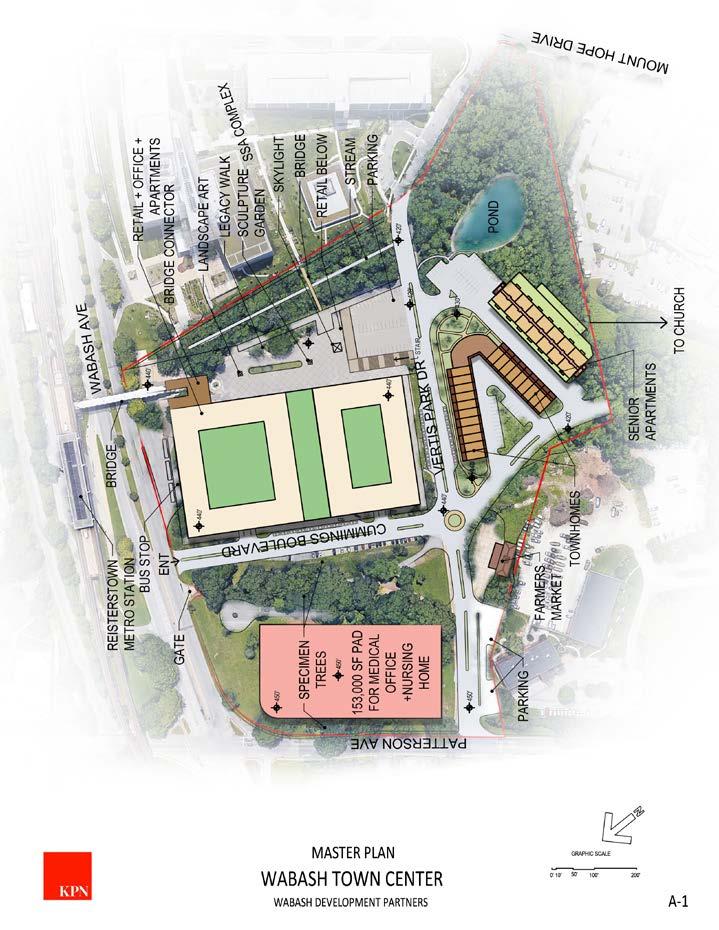
Phase 4: Medical and Health Care hub including offices, urgent care, health and fitness, nursing home/rehabilitation center and accessory retail. The total number of parking spaces is to be determined.
REISTERSTOWN METRO
PHASING PLAN
06
The building, each in Phase 1A and 1B are programmed as mixed use. They include retail, parking, offices and market rate apartments. Both buildings will be joined at the ground level to maximize the need for additional parking.
Two buildings, Phase 1A and 1B, will be constructed in the highest-density portion of the site and are programmed as mixed use. These properties include retail, parking, offices and market rate apartments. (Please see plan and Section) These buildings, with a total of apartment units, are the heart and anchor of the new community and are designed to take full advantage of the transit access.
These properties create the density to support retail and amenities - and a center point for the neighborhood as a whole.


The Market data indicate there is a high-demand, for quality, apartment living with good transit (and highway) access in this portion of Baltimore City and County. Units will be highly contemporary in design, capable of supporting the latest in tech accommodating the mixed of transit-based AND work-from-home lifestyles that are in demand in the post-COVID era.
PHASE 1B RAMP UP STORAGE GREEN ROOF STORAGE RAMP UP PARKING TOWER 1A OFFICE OFFICE T T T T PARKING TOWER 1B 50' WABASH TOWN CENTER WABASH DEVELOPMENT PARTNERS LEVEL 3-4 PLAN_PHASE 1A + LEVEL 3_PHASE 1B_OFFICE+PARKING 277'-0" 32'-0" 32'-0" 214'-0" 308'-0" 0' 10' 50' 100' A-5 12222221 1222211 1 1 1 1 1 1 1 1 1 1 1 1 1 1 3 1 2 1 12222221 1222211 1 1 1 1 1 1 1 1 1 1 1 1 1 11 2 111 3 1 1 1 1 1 1 1 1 2 12222221 1222211 1 1 1 1 1 1 1 1 111 3 11 12222221 1222211 1 3 2 PHASE 1A PHASE 1B APARTMENTS APARTMENTS GREENROOF GREENROOF 1-1BED+1BATH 2-2BED+2BATH 3-2BED+DEN+ 2BATH 50' WABASH TOWN CENTER WABASH DEVELOPMENT PARTNERS LEVEL 4-8 PLAN_PHASE 1A + LEVEL 4-5_PHASE 1B_MARKET RATE APT 277'-0" 32'-0" 32'-0" 214'-0" 308'-0" A-6 0' 10' 50' 100' 20'-0" 28'-0" 31'-0" 6'-0" 1 BED + 1BATH 570 SF 2 BED + 2BATH 850 SF CORRIDOR B L/D C T K C T K T D B L B C C 5' 0' 10' WABASH TOWN CENTER TYPICAL APARTMENT UNIT PLANS_PHASE 1A AND 1B 28'-0" 20'-0" 28'-0" 31'-0" 6'-0" 1 BED + 1BATH 570 SF 2 BED + 2BATH 850 SF CORRIDOR B L/D C T K C T K T D B L B C C A-7 5' 0' 10' WABASH TOWN CENTER WABASH DEVELOPMENT PARTNERS TYPICAL APARTMENT UNIT PLANS_PHASE 1A AND 1B 28'-0" PARKING
PARKING AREA MARKET RATE APARTMENT TYPICAL APARTMENT UNIT PLAN PHASE 1B RAMP UP STORAGE GREEN ROOF STORAGE RAMP UP PARKING TOWER 1A OFFICE OFFICE T T T T PARKING TOWER 1B 50' WABASH TOWN CENTER WABASH DEVELOPMENT PARTNERS LEVEL 3-4 PLAN_PHASE 1A + LEVEL 3_PHASE 1B_OFFICE+PARKING 277'-0" 32'-0" 32'-0" 214'-0" 308'-0" 0' 10' 50' 100' A-5
+OFFICE + APT


26'-0" 44'-0" RETAIL 456' 22'-0" 26'-0" 26'-0" 22'-0" 44'-0" APT OFFICE APT APT APT APT APT APT APT OFFICE RETAIL PARKING PARKING PARKING PARKING 532' 521' 510' 499' 488' 477' 466' 456' 22'-0" 26'-0" WABASH TOWN CENTER WABASH DEVELOPMENT PARTNERS PART BUILDING SECTION_PHASE 1A A-8 0' 5' 10' 20' BUILDING SECTION + RENDERING
Designed around the concepts developed by Carehous (carehous.net), this building will be housing for a senior population with living units for their caregivers. Carehaus’s work is founded on the belief that older adults, disabled people, and those who care for them are integral to the well-being of these senior communities. Communal spaces will be designed to encourage interaction between seniors and their caregivers through various programs.
This phase proposes 42 units of senior (age-restricted) multi-family housing units, 163 offstreet parking spaces and accessory common areas including a small bistro. The non-residential uses are intended for primary use by the residents.


PHASE 2B APARTMENTS WABASHWABASHTOWNCENTER DEVELOPMENTPARTNERS LEVEL3-5PLAN_PHASE2B_SLAPARTMENTS B-7 104'-0" 264'-0" 0'5'10'20'40' 2 11/2 11/2 11/2 11/2 11/2 11/2 11/2 11/2 11/2 11/2 2 2 2 WABASH TOWN CENTER WABASH DEVELOPMENT PARTNERS LEVEL 3-5 PLAN_PHASE 2B_SL APARTMENTS B-7 104'-0" 0'5'10'20'40' 2 1 1/2 1 1/2 1 1/2 1 1/2 1 1/2 2 2 - 2BED+2BATH ACCESSIBLE APARTMENT 1 1/2 - 1 BED+1DEN+1BATH ACCESSIBLE APARTMENT LEVEL 3-5 PLAN_PHASE 2B_SL APARTMENTS
THE VILLAGES OF WHITE MARSH

Studio Architect l Associate
KPNARCHITECTS, llc 2017 - Present
Brief Description of Project
Size : 20+ Acre
Design Start : 2017
Setting :Residential
The architectural standards proposed for the multifamily structures create a dynamic, cohesive and harmonious fit within the project as well as the overall community. The multifamily clusters are made up of “L” shaped buildings. The buildings act as a backdrop to the pedestrian and vehicular street patterns reinforcing and activating the space with building elements such as the outdoor balconies. The building configurations somewaht enclose the surface parking to aid in the screening of the parking from public view.
The exterior building material and color selctions were chosen based on their compatibility with the other residential building types within the project as well as the surrounding community. Permanence and sustainability were other key factors in the selection of the exterior materials.

Responsibility
Develop schematic design drawings for residential buildings at different phases of this project. Prepare graphic materials and designs for studies and/or presentations to the client. Develop design concepts, narratives, Revit models, 3D renderings, plans, sections, exterior elevations, and virtual reality presentations, as necessary, to effectively convey the design intent to clients.
10/12/2018
07

THE VILLAGES OF WHITE MARSH
UP UP STAIR 261'-8" 161'-1" ELEVATOR MACHINE ROOM TRASH ROOM STORAGE ELEV STAIR ELEV STORAGE COMPACT CAR STORAGE STORAGE COMPACT CAR Dwg. Name: 1 B E H THE VILLAGES OF WHITE MARSH B E H THE MEADOW MILL 3600 CLIPPER MILL ROAD, SUITE 228 BALTIMORE, MD 21211 WWW.KPNARCH.COM SCALE: 3/32" = 1'-0" GARAGE FLOOR PLAN 1 GARAGE FLOOR PLAN DN UP 261'-8" 161'-1" UNIT A 1095 SF UNIT A.1 1092 SF UNIT A 1095 SF UNIT A2 840 SF UNIT A2 840 SF UNIT B 1207 SF UNIT F 1515 SF UNIT B2 1207 SF STAIR STAIR UNIT A2 840 SF UNIT A2 840 SF UNIT D 1375 SF UNIT D 1375 SF UNIT E 1500 SF UNIT E 1500 SF UNIT A2 840 SF FIRST FLOOR PLAN (5) UNIT A2 1BR 29.2% (7) 1BR 41.1% (2) UNIT C2 1BR 11.8% (10) 1BR 58.7% (2) UNIT A 1BR 1D 11.8% (1) UNIT A.1 1BR 1D 5.9% (1) UNIT B 2BR 5.9% (9) 2BR & 41.2% (1) UNIT B2 2BR 5.9% (4) 2BR 23.6% 1BR 1D (2) UNIT D 2BR 11.8% (2) UNIT E 3BR 11.8% (3) 3BR 17.7% (3) 3BR 17.7% (1) UNIT F 3BR 5.9% 17 UNITS 100% 100% 100% IT/ ELEC CLOS IT/ELEC CLOS ELEV ELEV UNIT C2 964 SF UNIT C2 964 SF ELEVATOR LOBBY Dwg. Name: 2 3 4 5 6 7 B C F G K
B C F G K THE MEADOW MILL 3600 CLIPPER MILL ROAD, SUITE 228 BALTIMORE, MD 21211 WWW.KPNARCH.COM SCALE: 3/32" = 1'-0" FIRST FLOOR PLAN FIRST FLOOR PLAN UP BATHROOM 12'-4" 6'-11" 261'-8" 161'-1" UNIT A 1095 SF UNIT A.1 1092 SF UNIT A 1095 SF UNIT A2 840 SF UNIT A2 840 SF UNIT B 1207 SF UNIT F 1515 SF UNIT B2 1207 SF STAIR STAIR UNIT A2 840 SF UNIT A2 840 SF UNIT C 1265 SF UNIT C 1265 SF UNIT D 1375 SF UNIT D 1375 SF UNIT E 1500 SF UNIT E 1500 SF UNIT A2 840 SF (5) UNIT A2 1BR 29.2% (5) 1BR 29.2% (2) UNIT A 1BR 1D 11.8% (8) 1BR 46.9% (1) UNIT A.1 1BR 1D 5.9% (1) UNIT B 2BR 5.9% (9) 2BR & 53.1% (1) UNIT B2 2BR 5.9% (6) 2BR 35.4% 1BR 1D (2) UNIT C 2BR 11.8% (2) UNIT D 2BR 11.8% (2) UNIT E 3BR 11.8% (3) 3BR 17.7% (3) 3BR 17.7% (1) UNIT F 3BR 5.9% 17 UNITS 100% 100% 100% IT/ ELEC CLOS IT/ELEC CLOS Dwg. Name: 2 3 4 5 6 7 B C E F G THE VILLAGES OF WHITE MARSH B C E F G THE MEADOW MILL 3600 CLIPPER MILL ROAD, BALTIMORE, MD WWW.KPNARCH.COM SCALE: 3/32" = 1'-0" TYPICAL FLOOR PLAN TYPICAL FLOOR PLAN 70'-0" FRONT FACING ELEVATION SCALE: 3/32" = 1'-0" GARAGE LEVEL FIRST LEVEL SECOND LEVEL THIRD LEVEL FOURTH LEVEL Dwg. Name: C D G K THE VILLAGES THE MEADOW 3600 CLIPPER MILL BALTIMORE, WWW.KPNARCH.COM SCALE: 3/32" = 1'-0" FRONT FACING ELEVATION 1 FRONT FACING GARAGE FLOOR PLAN FIRST FLOOR PLAN TYPICAL FLOOR PLAN FRONT FACING ELEVATION
THE VILLAGES OF WHITE MARSH
MASTER BEDROOM CL WALK-IN CLOSET POWDER ROOM MECH UTILITY ROOM W D DEN/ OFFICE BALCONY KITCHEN LIVING/ DINING HWH BATHROOM S
Dwg. Name 1 UNIT A (1095 SF) SCALE: 1/8" = 1'-0" UNIT A (1095 SF) KITCHEN LIVING/ DINING MASTER BEDROOM CL WALK-IN CLOSET BATHROOM UTILITY ROOM D W BEDROOM BALCONY WALK-IN CLOSET HWH MECH BATHROOM S THE VILLAGES OF WHITE MARSH THE MEADOW MILL 3600 CLIPPER MILL ROAD, SUITE 228 BALTIMORE, MD 21211 WWW.KPNARCH.COM Dwg. Name 1 UNIT B (1207 SF) SCALE: 1/8" = 1'-0" UNIT B (1207 SF) MASTER BEDROOM WALK-IN CLOSET KITCHEN BATHROOM UTILITY ROOM BEDROOM BALCONY LIVING/ DINING MECH W D CL CL HWH S BATHROOM
WHITE
THE MEADOW MILL 3600 CLIPPER MILL ROAD, SUITE 228 BALTIMORE, MD 21211 WWW.KPNARCH.COM Dwg. Name KITCHEN BALCONY BATHROOM LIN CL WALK-IN CLOSET MASTER BEDROOM BALCONY MECH D CL CL BEDROOM LIVING/ DINING W HWH S UTILITY ROOM BATHROOM
VILLAGES OF WHITE MARSH THE MEADOW MILL 3600 CLIPPER MILL ROAD, SUITE 228 BALTIMORE, MD 21211 WWW.KPNARCH.COM UNIT A (1095 SF) UNIT C (1265 SF) UNIT B (1207 SF) UNIT D (1375 SF)
THE VILLAGES OF
MARSH
THE
Architecture
Multi-Family Building
SCHEMATIC FRONT ELEVATION
SCHEMATIC

SCHEMATIC FRONT ELEVATION

FRONT ELEVATION / LONG VIEW REAR ELEVATION / LONG VIEW
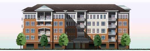


SCHEMATIC FRONT ELEVATION / LONG VIEW SCHEMATIC FRONT SCHEMATIC FRONT ELEVATION FRONT CLUBHOUS ELEVATION CLUBHOUS LOWER LEVEL CLUBHOUS UPPER LEVEL

CHICAGO MIDTOWN ATHLETIC
Architect Intern
CLUB
DMAC Architecture PC 2016
Brief Description of Project
Size : 100,000sf

Design Start : 2015
Constructions Start : 2017
Setting : Hospitality + Sport › Hotel Restaurant Sports Center Wellness/Spa

DMAC’s bold and progressive design for the new expansion of Midtown Athletic club seeks to create a new statement and revitalize the stretch of Elston Ave. creating an exciting and vibrant ‘Midtown Corridor’, acting as a beacon to the City’s premier Athletic Club. The project includes a 100,000sf expansion to their facility, to include multiple swimming pools, progressive fitness areas, spinning, yoga & pilates studios, lockers rooms, spa and a 3000 sf restaurant. The new design that also has a 25,000 outdoor pool deck would provide dramatic views of the city and integrate green design elements like roof gardens and vegetation.
Responsibility
Assists senior staff in verifying site details to support the design. Works with the project manager and project designer in creating buildings that serve the client’s needs and respond to their desired image, space, and aesthetic.
LANDING PIT KIDS CLUB PARKING GARAGE VESTIBULE SALES OFFICE CORRIDOR HOTEL MANAGER GM’S OFFICE LOBBY ACCESSIBLE ELEV CHNG ENTRY VESTIBULE WAITING ELEV SHWR SHWR SHWR OFFICE UNISEX SHWR SHWR RECEPTION INDOOR POOL DECK HYDRO.SPA POOL TEMP CLOSET STEAM TEMP CLOSET TEMP. CLOSET STEAM SAUNA ADA CHNG SERV ELEV JAN.CL MEN’S LOCKER MEN’S GROOMING CHNG ELEC PANEL RM LAUNDRY BOH CORRIDOR WATER HTR RM FIRE PUMP HEAD PRO ELEC PANEL (M) COMMON AREA MECH (W) SHOWERS (M) SHOWERS B.OH.CORRIDOR POOL STORAGE FLOOR 1 KEY PLAN N
08
FITNESS & HOTEL ROOM RENDERING


STAIR ST-1 CORRIDOR ELEV ELEV STORAGE OFFICE STAIR ST3(EAST) STAIR ST7 UTILITY OFFICE JAN CL FLOOR 3 KEY PLAN N RESTAURANT GOLF SIMULATOR FITNESS OFFICE GROUP SPINNING ELEVATOR EL-4 VESTIBULE GOLF SIMULATOR ELEVATOR LOBBY KITCHEN YOGA DRY STORAGE DRY STORAGE DRY STORAGE STAIR VESTIBULE VESTIBULE EL-02 STAIR ST1 WEST EL-01 BREAK RM MIND/BODY YOGA PREF LANDING PIT PILATES STAIR ST2 FLOOR 2 KEY PLAN N
KULA BELGRADE SERBIA
Architectural Designer
Brief Description of Project
Size : 42-floor, 168-meter (551 ft) tall
Design Start : 2015
Constructions Start : 2016
Setting : Mixed -use skyscraper
Skidmore, Owings & Merrill LLP 2017
Kula Belgrade is a 42-floor, 168-meter tall mixed-use skyscraper located in the Belgrade Waterfront on the bank of the Sava River, becoming the tallest building in the country. The tower will have a direct approach to a waterfront promenade, located in close proximity to Belgrade Fortress.
The tower, combining residential, commercial, hospitality and entertainment offerings, is made of concrete presenting steel structures on the podium on the ground floor, on secondary structures supporting the façade and on the top crown located on the top of the tower and developing for its last three floors.
The Kula Belgrade tower is the new landmark of the Serbian capital and is part of the 1.8 million square metre Belgrade Waterfront development, featuring world-class residences and offices, hotels, educational institutions, modern healthcare amenities, as well as a 1.8-kilometre long public waterfront edge and public parks.

Responsibility
Preparation of accurate architectural presentations, designs, details, and construction documents in REVIT, including plans, exterior elevations, and interior details.
09

NIGHT VIEW FROM PODIUM PLAZA
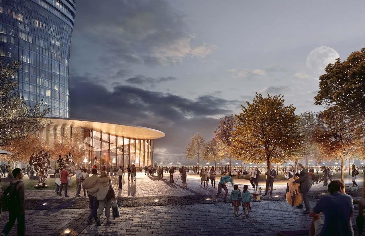
KULA BELGRADE
Note: As this project is under construction, the data is based on the most reliable information currently available.
Official Name Kula Belgrade
Name of Complex Belgrade Waterfront
Structure Type Building
Status Under Construction
Country Serbia
City Belgrade
Building Function Residential / Hotel
Proposed 2015
Construction Start 2016
Height: Architectural 168 m / 551 ft

Floors Above Ground 42
Tower GFA 47,000 m² / 505,904 ft²
CONSTRUCTION
BUILDING UNDER CONSTRUCTION


LIANG JIANG SALES DEPARTMENT DESIGN


Interior Designer
Zhong Heng Decoration 2009

Lianjian is a suburban county on the eastern coast of Fujian province, China. Due to its abundant amount of wet land resources in the Ming Jing River, Liangjian is flourished with rich fish resources. Not only does this contribute to economic growth, it further allows industries to develop and create more employment opportunities. And in 2009, I participated in the “LianJiang sales Department Overall Design and Planning”.
INTERIOR DESIGN
Design inspiration from the building’s location on the Lian Jiang River and its close relationship to the local fishing industry, I used waves as a motif, creating the image of the department using flexible, wavy lines.
HAND SKETCH HAND SKETCH 3D VIEW
10
SALES DEPARTMENTS 3D RENDERING

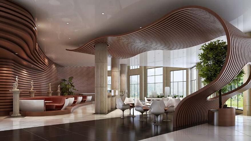
SALES DEPARTMENTS ELEVATIONS


SALES DEPARTMENT FINISHED WORK

Student Work
SUSTAINABILITY
Graduate Thesis 2016

Vernacular Informed Urbanity
Due to rapid developments in cities, it has radically disrupted the lifestyle and quality of living. This situation, where most apparent in developing cities, especially those of the rapidly growing third world countries, is a result to urbanization and current policies of development. Therefore, it is important for us to research and develop and understanding of people’s relationship with their city environments. Using Tulou and the Island of Santorini as case studies, this thesis will explore sustainable and qualitative elements of vernacular architecture. Closely studying the Kowloon’s Walled City as a model, sustainable urban living will be diagrammed, analyzed, modeled, and reviewed across diverse topics. Contemporary application of time-tested vernacular elements can inform developments that relates to urban natural systems. This helps to deepen current expectations and attitudes about contemporary life-styles, sustains urban ecologies, and attempts to create healthier relationships between traditional and contemporary lifestyles, thus creating a diverse living space with higher quality of living. This future city is imagined in a beautiful landscape between mountains and tea terrace fields in southeast China, a largely undeveloped rural region that will flourish massive growth in a short time span. The main idea of this thesis is thinking about how humans can respect, change nature and live with nature in the future.

OF
NEW ECOLOGIES
11

selected works 2009-2023


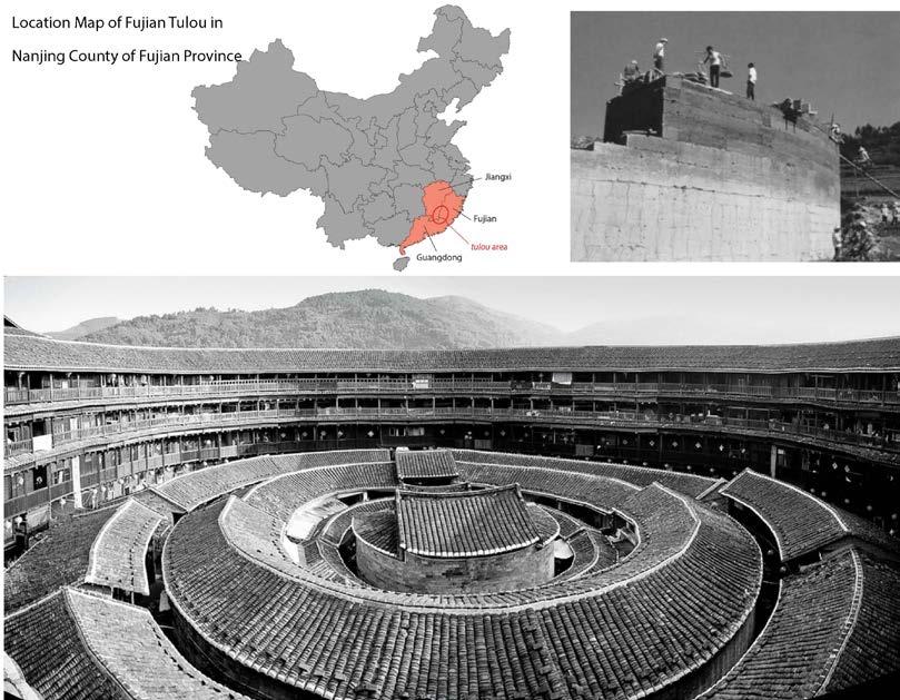
NANJING COUNTY
FUJIAN TULOU

Nanjing County is in the south of Fujian province. The western part of Nanjing locates many of the famous Fujian Tulou, where four of the 10 sites listed on UN-ESCO’S world heritage list are in Nanjin. The Fujian Tulou, known as “Fujian earthen buildings,” were built between the 12th and 20th centuries, where they are unique Chinese rural home to the Hakka, people of the southeastern China. The Longyan Xia men Rail-way, opened on June 30, 2012 was the first railway in Nanjing and the first railway to cross the county. The two stations connected to Nanjing station are the northeast counties, Shancheng and Longshan. The railway not only brings a lot of visitors from the major city Xia men, but also from Taiwan.

This is a concept model of the Chinese knot. As a long-standing form of cultural art, the Chinese knot is integrated with the quin-tessence of the Chinese culture, where ancient poets uses the knot as a metaphor to the complexi-ty of human emotions, especial-ly the sentimental love between men and women. Using the Chinese knot concept in architecture I begin to think about the potential spatial and relationship between the architecture, human and environment.


THE SITE PLAN OF NANJING COUNTY CHINESE KNOT DESIGN CONCEPT THE DIAGRAM OF


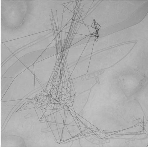


SITE MODEL & DIAGRAM STUDY HUMAN MIGRATION SITE PLAN STUDY


STUDY MODELS
The form of the building is representing and respect the mountains. Chinese architecture philosophy tends of to focus on the relationships between the various elements in nature . According to Daoist beliefs, man is a crucial component of the natural world and is advised to follow the flow of

PHYSICAL MODELS
Architectural models excel at conveying ideas in numerous ways and across various significant scales, including urban, architectural spatial, and detail.


THE FUTURE CITY OF NAN JING
This future city is imagined in a beautiful landscape between mountains and tea terrace fields in southeast China, a largely undeveloped rural region that will flourish massive growth in a short time span. The main idea of this thesis is thinking about how humans can respect, change nature and live with nature in the future.

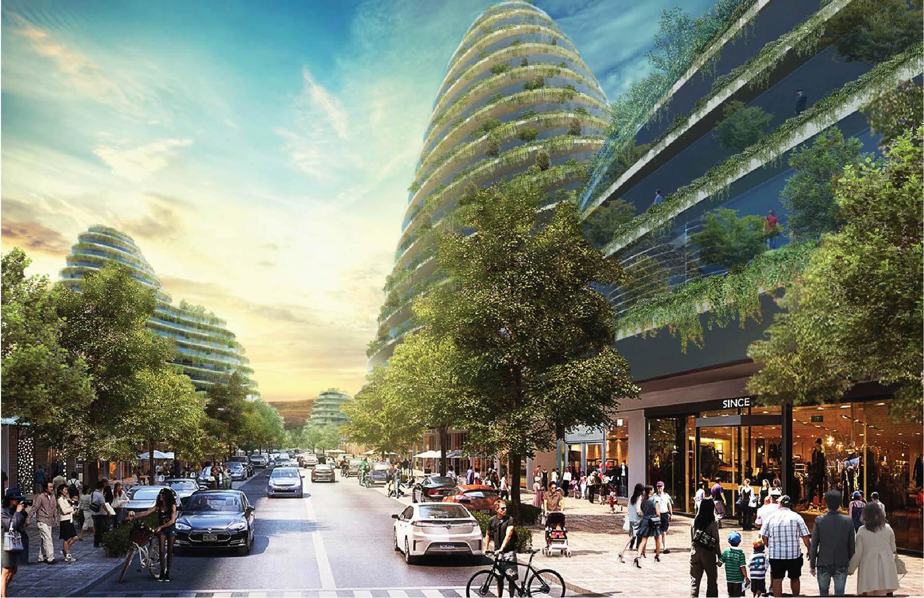
selected works 2009-2023
CHICAGO OBAMA PRESIDENTIAL CENTER
Student Work
Architecture Grad Studio 5


The Barack Obama Foundation recently issued an RFP proposing a new standard for Presidential Libraries. Differentiating itself from other Presidential Libraries, I design will create an innovative place of engagement and vibrant community hub.
The building will be multi-level new construction not to exceed 70,000SF. The site will also include significant public space connections to public transportation and commu nity thoroughfares.
12
SUSTAINABILITY : DAY LIGHTING
DESIGN CONCEPTS BUILDING STRUCTURE


The different sizes of rectangles and squares cavities on the walkways are designed to create different lighting effects during different times of the day. At day time, the sun will create skylights down into the parking garage. At night, the lights in the parking garage will illuminate the walkways from below.
The glass and steel are the predominant materials of the projects and the underground parking are complemented with concrete and steel structure.The structure of underground parking garage is directly related to the design of the aboveground walkways. The “Y” columns support are made with steel and concrete.

HYDE PARK HIGH SCHOOL PROPOSAL LIBRAY SITE JACKSON PARK JACKSON PARK CONNECTON CONNECTON JACKSON PARK ARCHIVE PRESIDENT OFFICE AREA CONNECTON CONNECTON JACKSON PARK JACKSON PARK CONNECTON CONNECTON HYDE PARK HIGH SCHOOL PROPOSAL LIBRAY SITE HYDE PARK HIGH SCHOOL PROPOSAL LIBRAY SITE HYDE PARK HIGH SCHOOL PROPOSAL LIBRAY SITE SCHOOL EDUCATION LIBRAY EXIHIBITION S STONY ISLAND AVE LIBRARY SITE LIBRARY SITE LIBRARY SITE LIBRARY SITE
PANORAMIC VIEWS
At the top of the Museum sits the Sky Room

The Museum’s Sky Room, located at the highest point, provides an opportunity for visitors to contemplate while enjoying breathtaking panoramic views of Lake Michigan towards the East, downtown Chicago’s towering skyscrapers in the North, and the West and South sides of Chicago.

This library serves as a bridge of education to business and social interaction; and potentially acts as a model that not only reshapes the site and surrounding neighborhood, but also the concept of what a Presidential Library can be in the future.


SITE ANALYSIS
selected works 2009-2023


A A COURTYARD LECTURE HALL PHOTO DISPLAY AREA PERMANENT EXHIBITION AREA MULTIMEDIA EXHIBITION AREA TEMPORARY EXHIBITION AREA GIFT SHOP LOBBY LIBRARY STUDY SITE PLAN
CAFETERIA AREA
NATURAL LIGHT CREATES SPACES.
Natural light creates a connection between the interior and exterior spaces.
The library’s interior space has been meticulously crafted with a stepped design that progressively widens the view as one ascends the floors, facilitating an interactive relationship between individuals and the interplay of space, light, and surrounding scenery.

The diamond-shaped roof design of the main library building not only allows natural light to illuminate the interior space but also offers a magnificent view of Jackson Park’s picturesque scenery.

The new Museum building in the South Side will serve as a significant landmark, inviting visitors to Jackson Park and highlighting the Center as a historical civic hub. The design of the Museum embodies the concept of upward movement from the grassroots.

INTERIOR STUDY SPACES

The forthcoming Chicago Public Library branch will present interactive digital media zones and child-friendly amenities, informative and vocational resources for adults, and a reading room open for everyone to relish. This exceptional collaboration is a pioneer in its category and will furnish almost all residents of the South Side with nearby public library access, with a walking distance.
The courtyard, in the center of a building, allows natural light to flow into the surrounding interior spaces, creating a brighter and more inviting atmosphere. Additionally, the design of the courtyard can provide a visual and physical connection between different levels or sections of the building, encouraging exploration and movement throughout the space. This dynamic and interconnected layout can create a more engaging and lively environment for visitors.

Student Work
FURNITURE DESIGN
Architecture Grad Studio 5
Through a series of hands-on technical exercises and material investigations, I chose cardboard as my primary design material in my furniture design course, and I was excited to explore its endless possibilities. Cardboard is an incredibly versatile material that is widely used in various fields. Its sustainability and ease of processing made it a preferred material for many industries. In addition, the unique honeycomb geometry structure of cardboard provided incredible strength and flexibility for furniture design. I utilized computer 3D modeling and laser cutting to achieve my design concept.

13
TOOLS, MATERIALS, AND TECHNIQUES
Laser cutting technology is a powerful tool that has revolutionized the way architects and designers create physical models, mock-ups, and prototypes. By using computer-aided design software (CAD), architects can create precise 2D and 3D drawings that can be easily translated into laser cutter-readable files. These files can then be used to create intricate and detailed physical models and prototypes using a laser cutter. Laser cutters use a high-powered laser beam to cut, etch, or engrave a wide variety of materials such as wood, plastic, metal, and even stone. One of the main benefits of laser cutting technology is its ability to create extremely intricate and precise designs with ease.
I was able to create complex geometric patterns, intricate textures, and detailed engraving with the laser cutter, which would have been difficult or impossible to achieve with traditional methods. This allowed me to quickly and accurately create a series of physical models of my furniture designs.

CNC INTEGRATED FABRICATION
Student Work
Architecture Grad Studio 2015
During my graduate studies in architecture, I took a course on CNC (Computer Numerical Control). Through the use of 3D modeling, I gained a fundamental understanding of the workflow from the computer to the machine and the post-processing steps required to finalize an object. During the course, I explored the various possibilities of CNC and the aesthetic outcomes of using the machine. By the end of the course, I felt confident in my ability to use the CNC machine for my individual projects, such as furniture design. I have since integrated CNC fabrication into my practice as a designer, artist, and maker.
Design and mill a custom bowl
Model Desk Accessory in Rhino
Mill out on CNC using Horizontal Finishing.

ART AND FURNITURE DESIGN

Computer Numerical Control (CNC) technology is revolutionizing the way that artists and furniture designers create their work. CNC machines use computer-controlled tools to precisely and accurately cut, shape, and carve a wide range of materials, from wood and plastic to metal and stone. This allows artists and designers to create intricate and complex designs that would be difficult or impossible to achieve by hand.
One major advantage of CNC technology is its ability to produce multiple copies of a design with perfect accuracy, ensuring that each piece is identical. This is particularly useful for furniture designers who need to produce a large number of pieces that are all the same.CNC machines also allow for greater precision and detail in the work, enabling artists and designers to create intricate patterns, shapes, and textures that would be difficult or impossible to achieve by hand. This opens up new possibilities for creative expression and experimentation in both art and furniture design.
Overall, CNC technology has revolutionized the way that artists and designers create their work, allowing them to push the boundaries of what is possible and to create works of art and furniture that are truly unique and innovative.


Design and mill a custom bowl
Model Desk Accessory in Rhino
Mill out on CNC using Horizontal Finishing

FINE ART HANDSKETCHES
Student Work
Undergraduate Art Studio 2007
During my four-year college experience, I took professional sketching courses to enhance my ability to represent three-dimensional space through techniques like sketching plaster casts or live models. These courses helped me refine my hand-drawing skills.


14
SKETCHING IS A VISUAL ART
During my graduate studies in architecture, I persisted in practicing sketching. By portraying architecture and landscapes, I consistently enhanced my comprehension of objects, space, and light. Sketching also enabled me to further cultivate my proficiency in visual representation, thereby facilitating more effective expression of my design concepts.
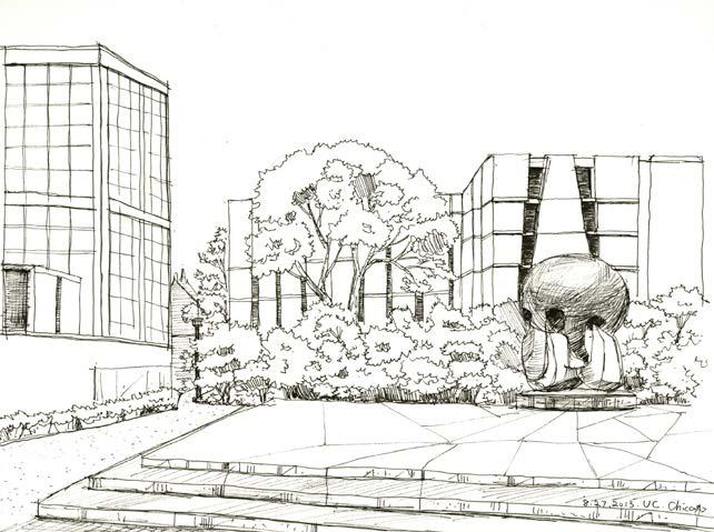
In my opinion, Sketching is a visual art that can help you improve your ability to express visually. Through sketching, you can learn how to accurately observe objects and depict observed details on paper. Sketching can help you better understand three-dimensional space and represent it in your drawings. This is crucial for architecture and interior design, which involve designing and utilizing space. sketching is highly beneficial for architecture and interior design, as it can help improve hand-eye coordination, visual expression ability, spatial awareness, creativity, and drawing skills, allowing you to better express your design ideas and concepts.

THE DOORS OF CULTURE


With a starting point of learning about doorway culture and design in Tokyo and Chicago, and thinking about how new materials and technologies transition into contemporary architecture, also plan to make scale model to apply these ideas to contemporary architecture and design.


Tradition Japanese doorways are so popular in Japan’s culture that they have come to be known in the western part of the world as one of the characterizing features of Japan and are definitely an iconic symbol of the country. Japanese gates have specific religious meaning, and more or less canonized building structure. In order to deeply discover different period doorway of traditional Japanese buildings, I took a lot of photos in Japan, not only in Tokyo but also in Nara, Kyoto, and Osaka. Taking inspiration from these cities, my fragments of memories evoke me to continue learning about transitions in Japanese traditional technology.

THE DOORWAY IN KYOTO AND
The Doorway in Chicago (Laser Cut Halftone Picture) 13.5inx17.5in
CHICAGO 2015
13.5inx17.5in
The Doorway in kyoto (Laser Cut Halftone Picture)
In this Winter Painting Institute, I focused on the development of independent projects in the context of painting. The aim of this intensive course is to provide an environment for actively questioning the parameters and ambitions of artistic practice. Process, experimentation, research and conversation will be prioritized over creating “finished” work.
ART EXHIBITIONS


This course was designed for experienced students who were interested in developing their skills in advanced painting techniques and conceptual thinking. Throughout the course, I had the opportunity to work on individual painting projects while receiving expert guidance and constructive feedback from instructors and peers. The program concluded with an exhibition at the studio gallery where I was able to showcase my work to the public.
In general, the painting course covered multiple aspects that helped me enhance my painting skills from various perspectives and skill levels of art appreciation. This included instruction on color theory, composition, brushwork, and other essential techniques, as well as exposure to diverse styles and genres of painting. By exploring these different areas, I was able to gain a more well-rounded understanding of painting and strengthen my abilities as an artist.
PAINTING INSTITUTE 2015
CHICAGO WINTER
The Cityscape of Chicago (Oil Painting on Canvas) 18inx24in
The stree view of Sunset (Oil Painting on Canvas) 18inx24in