9 minute read
Severe-service solutions

Robert Hsia, UnionTech, USA, introduces severe-service isolation solutions for hydrogen production via steam methane reforming (SMR).


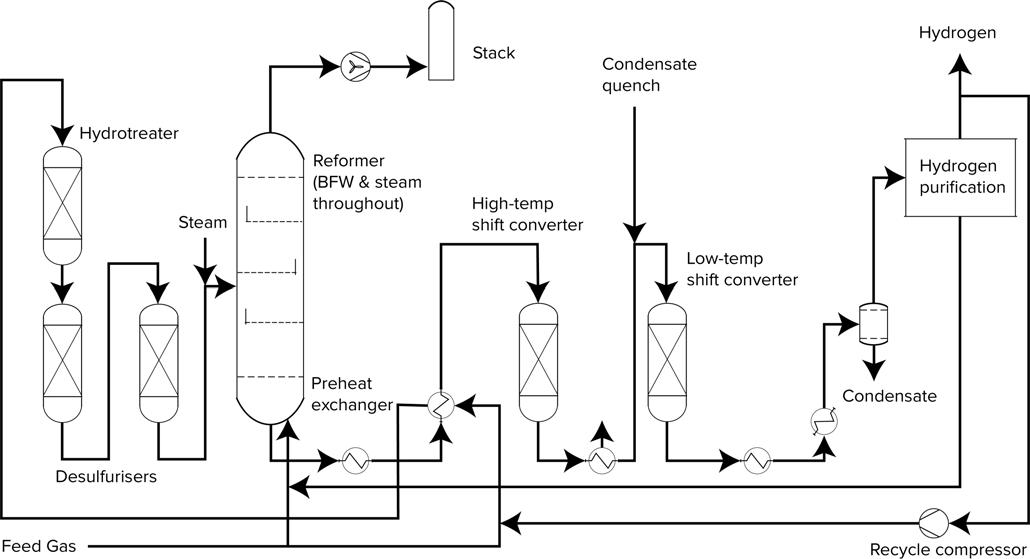
According to the US Department of Energy (DOE), natural gas reforming or steam methane reforming (SMR) currently accounts for 95% of the hydrogen produced in the US; it is arguably one of, if not the most, cost-effective and energy effi cient methods to manufacture hydrogen. Figure 1 depicts an overview of a typical SMR process. SMR is considered a mature production process whereby a methane source (i.e. natural gas, biogas, syngas, etc.) reacts endothermically with high-temperature steam in the presence of a catalyst to yield hydrogen, carbon monoxide, and carbon dioxide:

CH4 + H2O (+ heat) → CO + 3H2

Subsequently, the carbon monoxide and steam are reacted in the presence of a catalyst to produce additional hydrogen and carbon dioxide in regard to the ‘water-gas shift’ reaction:

CO + H2O → CO2 + H2 (+ heat)

Finally, the hydrogen gas is purifi ed via pressure swing adsorption (PSA), which removes carbon dioxide and other impurities. Oftentimes, an ammonia plant will exist downstream from the hydrogen plant, whereby the hydrogen is reacted with nitrogen to yield ammonia.

Isolation challenges posed by severe-service environments
The combination of high temperatures and pressures results in a severe-service environment which presents signifi cant challenges to fl uid isolation requirements. At the reformer and steam generator, temperatures and pressures can reach or exceed 1500°F and 1500 psig respectively. These elevated temperatures and pressures are prevalent throughout various modules of and applications within the SMR process, including the reformer, boiler feed water, feed gas lines, steam drum bridles, purging applications and blowdown applications.
Beyond the SMR island and at the ammonia section of the plant, these temperature and pressure challenges also persist throughout the nitrogen applications – as an example, nitrogen supply valves to compressors and fl are headers may reach or exceed 4000 psig at 400°F.
As the world advances on renewable energy initiatives, hydrogen has been gathering strong momentum as a ‘strategic pillar’ for energy transition, as it is a clean-burning molecule and a potential substitute for fossil fuels. Combined with carbon capture and sequestration (CCS) technologies, the SMR process enables the conversion of conventional hydrogen production, referred to as ‘grey hydrogen’, to the production of low-carbon hydrogen, otherwise known as ‘blue hydrogen’. For blue hydrogen to become economically viable as a primary energy source, the costs across the entire hydrogen value chain, including production, storage, distribution, etc., need to be reduced to meet the DOE’s cost targets for future automobiles and other applications. With respect to hydrogen production, the SMR process remains as the most cost-effective method as compared to others, such as electrolysis. Although the SMR process is considered a mature technology, both commercial and environmental optimisation opportunities exist and are being realised via sustained higher temperatures and pressures in particular areas of the process. For example, the Hydrogen Council and McKinsey & Co. assert that: “conducting ATR [autothermal reforming] at higher temperatures can also increase the methane-to-hydrogen conversion rates, resulting in lower methane content in the product gas, further reducing emissions.”1 As a result, new plants are designed to run much hotter and at higher pressures in specifi c applications and modules as compared to those in existing facilities. Moreover, the effi cacy of a true closed-loop system without leaks to atmosphere become critically important, from both a commercial and environmental perspective. As such, reliable isolation with positive shutoff becomes not only much more challenging for the valves in these applications, but also vitally important for the entire production process.


Valve selection from general service to severe-service
At lower temperatures and pressures, torque-seated gate valves, often equipped with either solid Stellite® or Stellite-welded overlay trims, may suffi ce for applications that do not require tight shutoff. Torque-seated valve designs involve the application of substantial forces to the valve components to adequately seal against line pressure. Over time, these forces wear down the critical sealing components of these types of valves resulting in shortened product lives vs those of position-seated valve designs.
As temperatures and pressures rise, gate valves are often replaced by Y-pattern globe valves, similarly equipped with either solid Stellite or Stellite-welded overlay trims, to achieve improved shutoff performance at initial installation. Unfortunately, the improved shutoff performance of globe valve is offset by substantial pressure drop across the valve and short product longevity.
The design of a globe valve involves a tortuous fl ow path that results not only in a high pressure drop (reduced Cv), but also in persistent erosion to its sealing elements. Furthermore, globe valves, like gate valves, are also torque-seated, which must be ‘hammered-down’ to seal against line pressure, resulting in sustained wear to the internal components of the valve. Combined with multi-turn and rising stem mechanics, the sealing effi cacy of globe valves is often compromised by these factors, resulting in packing leaks to atmosphere throughout the life of the valve. In addition to packing leaks, seat leaks often plague the performance of globe valves, as a temperature differential between the upstream and downstream sections of a closed globe valve results in thermal expansion of the inlet side of the valve vs thermal contraction of the outlet portion of the valve, which contains the plug. As such, the sealing effi cacy of the plug and seat is compromised, and the globe valve will leak through downstream.
To address the underperformance of globe valves in severe-service applications, companies such as Union Tech engineer and manufacture quarter-turn, metal-seated fl oating

Figure 1. Overview of a typical SMR process.
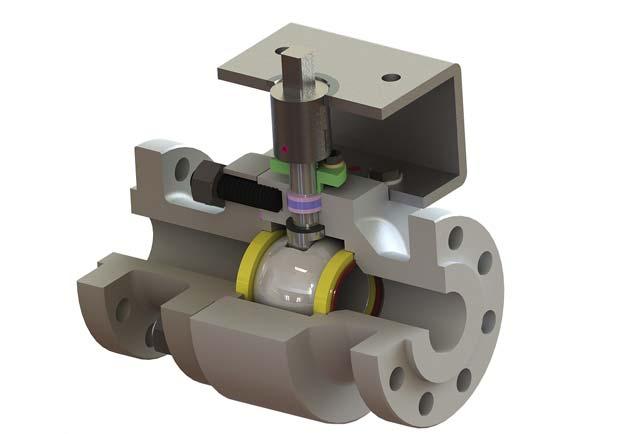
Figure 2. Cutaway of a two-piece severe-service MSBV.
ball valves (MSBVs) that can achieve a ‘bubble-tight’ seal per ANSI FCI 70.2 Class VI shutoff – or better. Figure 2 shows a cutaway image of a severe-service MSBV. The quarter-turn mechanics of a MSBV not only eliminates packing leaks, but also enables the usage of low emissions packing that complies with prevailing fugitive emissions certifi cations, such as API STD 641. Furthermore, the position-seated design of a MSBV utilises the line pressure to assist in sealing, which results in a substantial increase in valve longevity and reduction in maintenance/replacement costs. Moreover, the straight-though fl ow path not only eliminates the pressure drop across the valve, but also protects sealing components from erosive damage. These major design advantages have resulted in the widespread replacement of globe valves, not only in SMR applications, but also in other severe-service applications in power plants, refi neries, etc.
Features and considerations of severe-service MSBV designs
By defi nition, MSBVs incorporate a metal-to-metal seal; without appropriate coatings, the metal-to-metal components would gall during operation. Severe-service MSBVs apply high performance, hard-faced coatings to protect valve components against not only the galling of sealing surfaces, but also the wear, erosion and corrosion that threaten the long-term performance of the valve. After the application of the coatings, the sealing components are then mate-lapped to achieve zero leakage shutoff. Severe-service MSBVs are custom engineered products, and as such, coatings are often customised for a particular application. As an example, certain purge valves in the SMR may operate at 570 psi and 775°F with infrequent cycling. Union Tech’s high velocity oxygen fuel (HVOF) chromium carbide coating would be appropriate for this particular application.
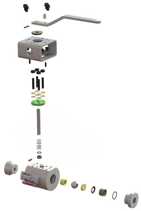
Of the available MSBVs in the marketplace, manufacturers may employ several designs, each with their own advantages and disadvantages. For example, some MSBVs utilise an integral downstream seat, machined out of the valve body. This design realises the benefi t of cost reduction, but it sacrifi ces performance as the valve trim and body typically consist of different materials with different coeffi cients of thermal expansion. Other designs, such as Union Tech’s Z1 MSBV, utilise matched ball and seat materials with identical coeffi cients of thermal expansion – the downstream seat is hydraulically pressed into the body, which eliminates any voids that could arise from seat distortion during the process. Figure 3 provides an image of the components of a unibody severe-service MSBV with a pressed-in seat design. The ball is then ‘fi nal lapped’ to the pressed-in seat to ensure the sealing integrity of the ball and seat following installation. Although more costly, this design elects product robustness and performance scope expansion over cost minimisation.
MSBVs are commonly equipped with mounting bracketry and stem adaption components for actuation. The importance of the mounting bracketry and stem adaption designs is often overlooked and, as a result, often a source of valve package failures in the fi eld. First, the height of the mounting bracket should be determined by both the line temperature and valve orientation (i.e. horizontal or vertical) to safeguard the actuator, controls, and accessories from excessive heat radiation. Most engineering departments of MSBV manufacturers have access to heat dissipation curves specifi c to their valve packages and should be able to provide guidance on appropriate bracket heights (and in more extreme cases, heat shields and other heat dissipation equipment) specifi c to each application. Second, mounting bracketry and stem adaption components should be engineered to ensure that the axis of rotation is centred and stabilised throughout the length of the stem. In the case of vertical piping, gravity applies an orthogonal force to the stem, further challenging the stability of the rotational axis. Insuffi cient support of the stem in relation to suboptimal mounting bracketry and stem adaption designs often results in


Figure 3. Components of a unibody severe-service MSBV with a pressed-in seat design.
SEEING IS BELIEVING
stem misalignment or side-loading. Valves with side-loaded stems will operate with substantially increased operating torques or seize completely; inspection of components will reveal galling on stem and other internal components of the valve.
Other features common to severe-service MSBVs include: One-, two-, or three-piece design. Uni or bi-directional sealing. Customisable end connections. Blowout proof stem design. Scraper seats. Purge ports, steam jackets, etc. Fugitive emissions performance certification (i.e. API 641). Safety integrity level certification (i.e. SIL-3).
Conclusion
Hydrogen is one of the key pillars for energy transition, and investment into effi cient production methods is crucial for success. As these new process technologies leverage effi ciencies from increased temperatures and pressures, robust and dependable isolation solutions are necessary throughout the production facilities. Severe-service MSBVs employ technologies that have been fi eld-tested across many other industrial applications and can provide new hydrogen production plants with necessary and ideal valving solutions.
Reference
1. McKinsey & Co., ‘Hydrogen Insights: A perspective on hydrogen investment, market development and cost competitiveness’, (February 2021).


