
12 minute read
The best of blue hydrogen


Yassir Ghiyati, Nitesh Bansal, and Mohammed Ilyas, Haldor Topsoe, Denmark, provide a review of the best available blue hydrogen technologies.


Carbon dioxide (CO2) emissions must be reduced to tackle global warming. Several governments have therefore already adopted relevant regulatory frameworks, such as emission trading schemes or carbon taxation, with the aim of reducing CO2 emissions.
As just one example, the EU Emission Trading System (ETS) directive drives CO2 reductions by setting a cap on the total CO2 emission allowance for each company and by reducing this cap fi gure over time. Companies can sell their surplus quotas of CO2 emission and are thus incentivised to invest in the most effi cient technologies with least CO2 formation and to capture, utilise and/or sequester the formed CO2.
Since its introduction in 2005, the EU ETS directive has passed through several phases. It is now in its fourth phase, in which the pace of annual cap reduction is set to increase signifi cantly. The EU commission expects the directive to drive faster adaptation of both ‘blue’ and ‘green’ technologies that are essential for the EU’s journey towards climate neutrality by 2050.
According to the International Energy Agency (IEA), annual hydrogen production accounts for 830 million t or 3% of global CO2 emissions. As such, there is a need to

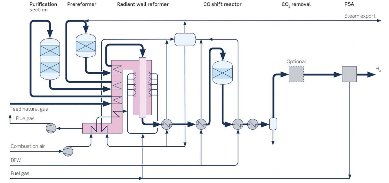
Figure 1. Traditional steam methane reforming.
decarbonise hydrogen production. However, the potential role that hydrogen can play in the net zero carbon economy is much greater as it can decarbonise other sectors as well by becoming a preferred energy carrier, either in its pure form or by being converted into ammonia. The Hydrogen Council estimates that H2 production will increase 8 – 10 times by 2050, emphasising the need for decarbonising H2 production.
Hydrogen is traditionally produced by steam methane reforming (SMR) using fossil-based feedstocks such as natural gas, LPG or naphtha. Hydrogen production from fossil sources without CO2 capture is termed ‘grey hydrogen’.
One promising way of decarbonising hydrogen production is by steam electrolysis fuelled by renewable energy. The hydrogen produced this way is completely green and leaves no CO2 footprint, whether from production or use. Companies such as Haldor Topsoe have commercialised electrolysis solutions that are easy to use as standalone hydrogen units or in hybrid setups in combination with traditional hydrogen production. However, one of the main limitations of green hydrogen deployment at mega scale currently lies in the insuffi cient availability of green power capacity.
To unlock the full potential of hydrogen in the energy transition aimed at reducing CO2 emissions, it is therefore necessary to supplement green hydrogen with other clean hydrogen sources with a low carbon footprint (known as ‘blue hydrogen’). Such hydrogen can be formed by combining traditional production methods with clean technology innovations. Blue hydrogen can therefore be produced either by revamping an existing grey hydrogen plant or by constructing a grassroot blue hydrogen plant.
The defi nition of blue hydrogen is not yet completely agreed, but many key industry stakeholders correlate blue hydrogen with >90 – 95% CO2 recovery. One weakness of this defi nition, however, is that it disregards the inherent carbon intensity of the different hydrogen production methods. To discuss this important point, it is necessary to review the main methods used to produce hydrogen in greater detail.
Hydrogen production technologies
Steam methane reforming
SMR is currently the technology most widely used to produce hydrogen. The main reforming process occurs over nickel-based catalysts inside tubes placed in a hot reformer chamber (Figure 1).
The steam reforming of hydrocarbons can be described by the following reactions:
Cn H m
+ n H2O → n CO + [n+½m] H2 - heat (1) CH4 + H2O ⇄ CO + 3 H2 - heat (2) CO + H2O ⇄ CO2 + H2 + heat (3)
Reformer heat is generated by burning fuel gas, which is usually a combination of natural gas and pressure swing adsorption (PSA) off-gas but can also include other off-gas streams imported into the hydrogen plant. Waste heat from the fl ue gas is recovered by preheating the feedstock and by steam generation, before the CO2 rich fl ue gas is vented into the atmosphere. The hot process gas exiting the reformer contains a mixture of steam, H2, CO and CO2. This is cooled in a waste heat boiler generating utility steam before it is sent to the shift section where CO reacts with process steam to create more hydrogen and CO2.
The effl uent from the shift reactor is normally sent to a PSA unit to separate pure hydrogen from the off-gas, which is sent to the reformer as fuel. In low hydrogen purity applications, the PSA unit can be avoided or replaced with a methanator.
In a blue hydrogen scenario, the CO2 in the process gas from the shift section is recovered in a CO2 removal unit before being sent to the PSA/methanator.
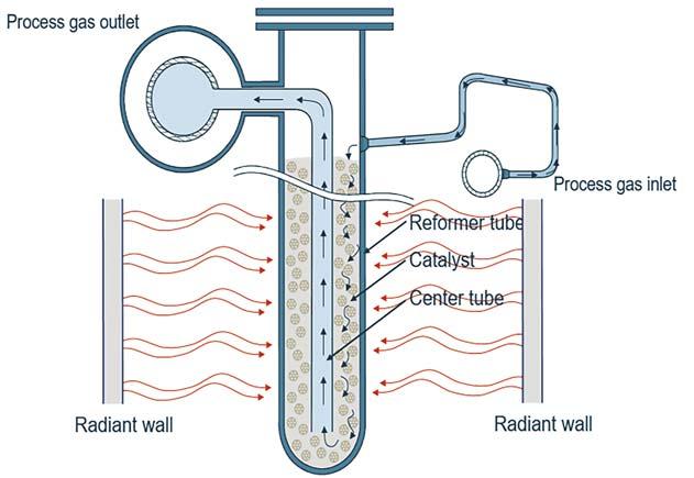
Figure 2. SMR-B reformer sketch.
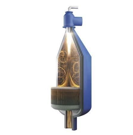
Figure 3. SynCORTM reformer.
Depending on the reduction targets for CO2 emissions, it may also be necessary to add a flue gas CO2 capture unit.
Heat exchange reforming
In some cases, steam generation in the hydrogen plant is not a viable solution, due to plant economics or CO2 footprint. In such cases, the surplus energy can be utilised to drive additional reforming by either adding a heat exchange reformer (HTER) reactor downstream of the SMR or by modifying the design and operation of the SMR itself. Both options have been successfully used in industry.
In both HTER and SMR-B, the steam export is significantly lower than traditional SMR technology, hence the fuel consumption is lower per hydrogen yield, resulting in lower CO2 footprint.
In an HTER layout, a portion of the feedstock bypasses the SMR and is instead fed into the HTER reactor, where it is heat exchanged with the hot effluent from the SMR. The reforming taking place in the HTER reactor results in an additional 25 – 30% more hydrogen production and is therefore also a good option for adding capacity to an existing hydrogen plant.
As mentioned above, another option is to alter the SMR design, using advanced bayonet catalyst tubes to capture heat from the effluent before it leaves the SMR. This bayonet design is referred to as SMR-B (see Figure 2).
At high capacities, conventional SMR design is limited by the economical size of the reformer. Heat exchange reforming has been successfully deployed to extend the single train capacity limit up to 207 kNm3/hr.
Convection reforming
For hydrogen production capacities below 30 kNm3/hr, convection reforming (HTCR) is normally a better option than SMR. In convection reforming, the reformer design is different since the tubes are bundled in a much smaller chamber and the heat required for the process is generated by a single burner. The tubes are in contact with the flue gas generated by the burner flame in a convection section.
HTCR design provides heat integration with no steam export and is therefore favoured in cases where steam is not a desired product or is less valuable than hydrogen.
The compact design of the HTCR unit favours modularisation and has thus been the preferred choice for small scale hydrogen production for decades.
Advanced autothermal reforming
SynCORTM reforming is an advanced autothermal reforming (ATR) process, which is fundamentally different from the tubular steam reforming processes described above in the sense that the main reforming process takes place inside one SynCORTM reactor. The reactor has a compact design consisting of a refractory-lined pressure vessel with a burner, combustion chamber and a catalyst bed (Figure 3).
The process gas enters the SynCORTM reactor and is mixed with oxygen and additional steam resulting in a combination of partial combustion and steam reforming.
Among blue hydrogen technologies, this process has low OPEX since the reactor operates at a steam to carbon ratio of 0.6, which is 3 – 5 times less than SMR. The lower steam throughput also has the benefit of reduced equipment and piping sizing –a benefit that is most pronounced at large scale since the equipment and piping are kept within standard sizes even at very large single line capacities.
SynCORTM technology has a proven track record from more than 80 years of industrial operation. The largest SynCORTM reactor in operation today has a hydrogen production capacity of 500 kNm3/hr, and the economical limit for single train capacity is 825 kNm3/hr.
In SynCORTM, the external fuel demand is extremely low, hence a very high carbon recovery (>95%) can be obtained without needing to capture the carbon in the flue gas. It is therefore very well suited for blue hydrogen.
Partial oxidation
Hydrogen can also be produced by partial oxidation (POx). It is a non-catalytic process where a fuel-oxygen mixture is partially combusted resulting in a hydrogen
rich syngas, which is then shifted before being sent to product purification.
The partial oxidation reaction occurs when a sub-stoichiometric fuel-oxygen mixture is partially combusted in a series of partial oxidation reactors. This chemical reaction takes the general form:
Cn H m + n/2 O2 → n CO + m/2 H2
The POx technology has certain well-known limitations, including: Continuous formation of soot, which must be removed frequently. Relatively high CAPEX due to the need of multiple reactor design, large air separation unit (ASU) and soot removal unit. High consumption of oxygen and power. Very high operating temperatures (1300 – 1400°C), which significantly limits the service life of the burners. Complicated water-cooled oxygen burner.
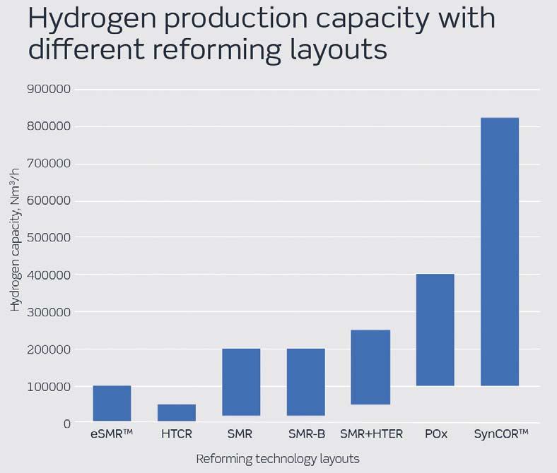
Figure 4. Optimal single line hydrogen production capacity with different reforming technology layouts.
Electrified steam methane reforming (eSMRTM)
A new hydrogen production method is electrified steam methane reforming (eSMRTM). In this method, the main reforming reactions take place inside a catalytic reactor with reaction heat being generated by an electrical current. This means no hydrocarbon fuel is used in the reformer, which in turn means there is no reformer flue-gas. The energy density of an eSMRTM results in a reactor size that is a fraction of an SMR unit.
Furthermore, practically all the CO2 in the shifted process gas can be recovered at low cost in a CO2 removal unit, making this process a very good candidate for blue hydrogen production in cases where electricity prices are favourable.
The eSMRTM process has been successfully tested at pilot scale and will soon be tested in a demonstration plant.
Comparing layouts
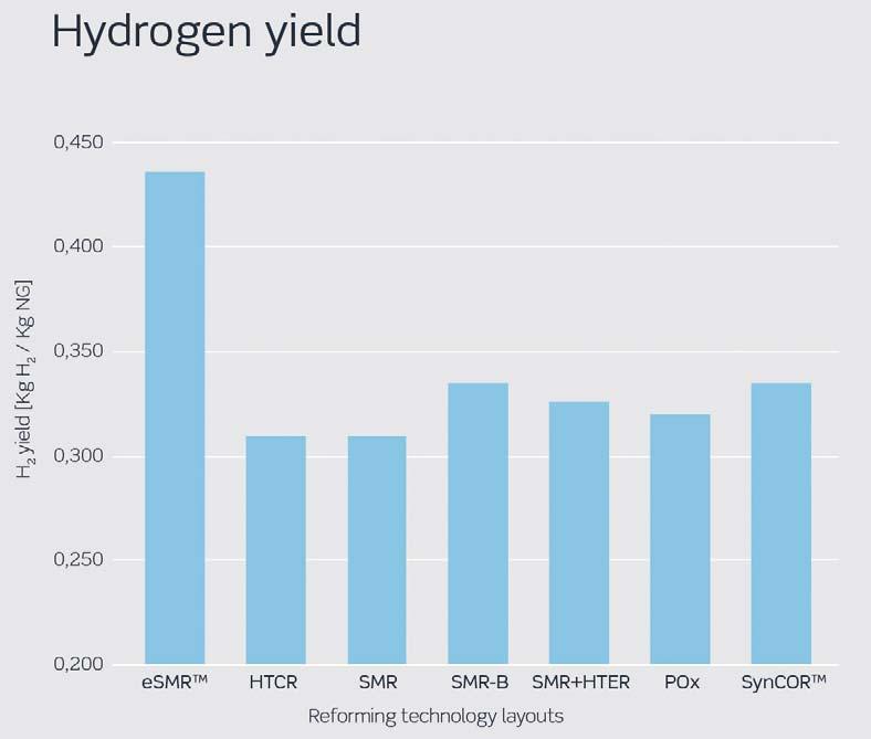
Figure 5. Hydrogen yield for different hydrogen production technologies.
All the technologies mentioned above can be used to produce blue hydrogen. Selecting the technology best suited for any project will depend on multiple parameters, including capacity, yield and carbon intensity, as well as the levelised cost of hydrogen (LCOH).
A technology comparison of the main parameters is presented below starting with production capacity in Figure 4.
At small capacities, HTCR and eSMRTM are the most suitable technologies due to their compact design, whereas SynCORTM is the preferable choice at higher capacities because of low CAPEX. Its single reactor layout and very low steam-to-carbon ratio operation enables the SynCORTM design to benefit more from economy of scale.
The ‘hydrogen yield per consumed natural gas feedstock’ is very high in eSMRTM due to its fundamentally different design with electrically heated reformer (see Figure 5). Among other technologies, SynCORTM and SMR-B have the highest yields. For SMR design, this is lower due to steam export, which is sometimes necessary to balance steam requirement outside the hydrogen plant.
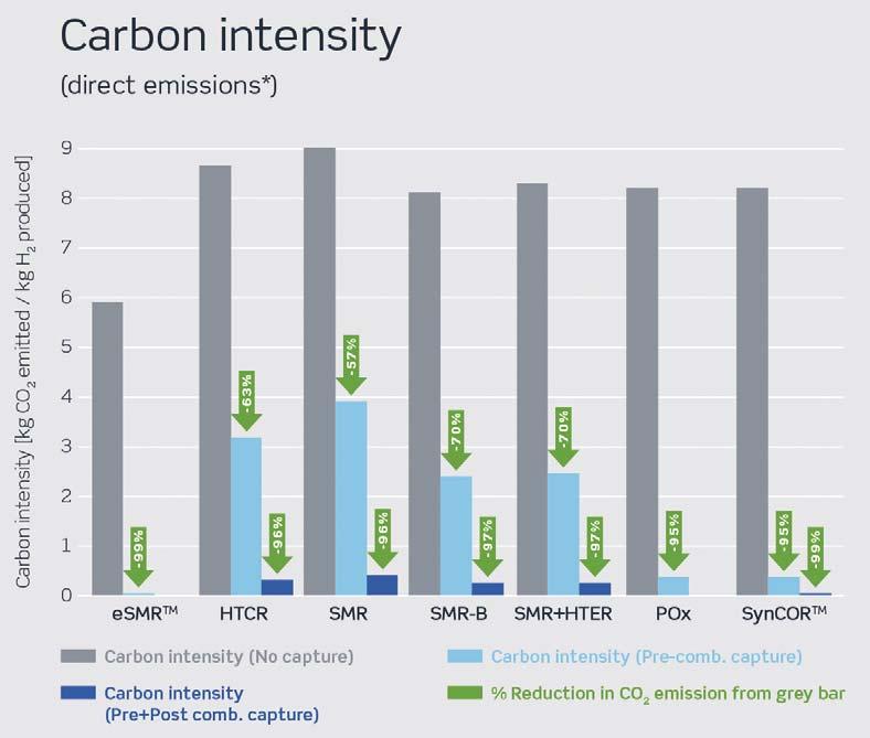
Figure 6. Carbon intensity of different blue hydrogen technologies.
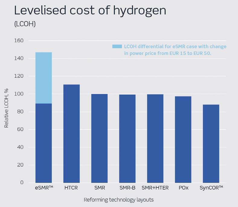
Figure 7. Levelised cost of hydrogen for different reforming technologies. Main assumptions: natural gas: €4/million Btu, power: €50/MWh (power cost is varied from €15 – 50/MWh for eSMRTM to demonstrate cost sensitivity), CO2 credit: €25/t.
Carbon intensity (CI) is now widely considered the most effective way to measure the success of a blue hydrogen technology in terms of reductions in CO2 emissions. In Figure 6, CI is shown as the mass of CO2 emitted per unit of hydrogen produced. The grey columns, which show CI with no carbon capture, are highest for the SMR design due to its lower efficiency and higher fuel consumption, converting waste energy to high levels of steam export. SMR-B has the lowest inherent CI among conventional technologies, since it has no steam export, whereas eSMRTM CI is a step change better due to the nature of electrified reforming.
CI can also be reduced by capturing CO2 from the process gas. This is more economical than capturing CO2 from flue gas and is therefore normally the first step in CO2 capture. In Figure 6, this is shown as light blue columns. For SynCORTM and POx, which are both oxygen fired processes, as well as for eSMRTM, achieving very low CIs is fully feasible by removing the CO2 formed in the process gas only. This feature makes these processes ideal for blue hydrogen production.
Going from light blue to deep blue hydrogen requires the removal of CO2 from the flue gas. This is most cost-effectively done in SynCORTM, due to lower levels of flue gas relative to hydrogen yield. It is not a necessary step for eSMRTM, since there is no flue gas in an eSMRTM plant.
The choice of technology ultimately depends on achieving certain targets as cost-effectively as possible. Figure 7 shows the relative differences in LCOH for each technology.
At the same operational targets and conditions, the hydrogen produced in SynCORTM has the lowest levelised cost, mainly due the combination of high yields, lower CAPEX and lower OPEX. However, eSMRTM is envisioned to be a better technology choice in niche conditions with low electricity prices and at small to medium production capacities.
Keep up to date with us to hear the latest downstream oil and gas news


