9 minute read
A new way to lower sulfur
disulfi de oils (RSSR or DSO), which are then removed from the caustic. The regenerated (or lean) caustic is then returned to again interact with the hydrocarbon, extracting more acidic sulfur species.
The extraction and oxidation reactions of mercaptan (RSH) and caustic (NaOH) are shown here:
While it is relatively easy to reduce extractable RSH in the product to 1 – 2 ppm as sulfur (S), one of the largest challenges to caustic treating is preventing the resulting DSO from returning to the hydrocarbon feed. The DSO is typically both entrained and dissolved in the oxidised caustic. The colloquial term for the DSO which returns to the treated hydrocarbon is ‘re-entry sulfur’ or ‘back extraction’.
To achieve the low sulfur requirements, Merichem Company offered its REGEN® ULS technology, which reduces DSO back extraction allowing total sulfur product specifi cations below 10 ppmw. Merichem designed the REGEN ULS technology by combining two separate existing technologies in such a way as to force the DSO to separate more completely from the regenerated caustic compared to a traditional REGEN system.
Pairing a high-effi ciency RSH removal system (THIOLEXTM) with a specially designed REGEN ULS, where total DSO back extraction is reduced to only 1 – 2 ppm as S, allows for a much lower total S product specifi cation compared to a standard REGEN.
The fi rst REGEN ULS unit was installed in Taiwan over 10 years ago and has since been successfully operating and meeting product specifi cations.
Caustic Extraction: RSH+NaOH ⇒ NaSR+H2O
Oxidative Regeneration:
Catalyst2NaSR + O2 + H2O RSSR + 2naOH
Technology advantages
The THIOLEX technology utilises caustic soda as the treating reagent to remove acid gas and mercaptan compounds from liquid hydrocarbon streams. The non-dispersive FIBER FILM® Contactor used in the technology enables reduced CAPEX and less plant space requirements compared to most treating alternatives. The large interfacial surface area, microscopic diffusion distance and continuous renewal of the aqueous phase when using the Contactor combine to yield greater mass transfer effi ciencies. Because the aqueous phase adheres to the fi bres in the Contactor rather than being dispersed into the hydrocarbon phase, aqueous carryover is virtually eliminated.
The FIBER FILM® Contactor was designed as an improvement to conventional caustic/hydrocarbon dispersive mixing designs such as trays and mixing valves. It reduces caustic carryover with the hydrocarbon after the contacting and reduces the size of the separation vessels.
The patented REGEN ULS achieves low total S in the lean caustic by using up to three DSO-removal steps: The bulk free DSO is first decanted. Next, the caustic is solvent washed to remove most of the dissolved DSO. Finally, for DSO polishing, the caustic flows through a DSO adsorption bed.
This three-step process allows a near total elimination of DSO re-entry sulfur in the treated product.
In many cases, butane can be treated pre-fractionation in a single train compared to conventional technologies requiring treatment of multiple trains post-fractionation.
In this case study, total mercaptan sulfur content of the BB feed was reduced from 222 ppmw to less than 2 ppmw for combined mercaptan and DSO.
Description of the process
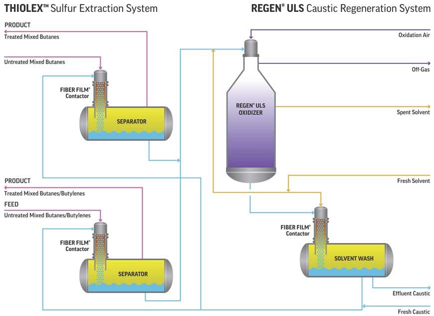
Figure 1 contains a schematic fl ow diagram of Merichem’s THIOLEX/REGEN ULS treating unit with untreated BB. The hydrocarbon stream is treated in a THIOLEX system using lean caustic from the REGEN ULS. The untreated BB stream has a design throughput of 13 000 bpd and total mercaptans of 222 ppmw as sulfur. After treatment in the THIOLEX unit, the sum of remaining mercaptan plus DSO as sulfur is reduced to 2 ppmw. The mercaptide-rich caustic is directed to the REGEN ULS system, where it is oxidised on a fi xed catalyst bed. The resulting DSO is then removed from the caustic using fi rst bulk phase separation and decanting, then solvent washing, and lastly adsorption on a fi xed bed (not indicated) to yield the ultra-low sulfur (ULS) lean caustic that is recirculated to the THIOLEX unit for continuous treating. The technology super-regenerates the mercaptide-rich caustic and returns a lean caustic almost free Figure 1. Schematic diagram of the THIOLEXTM and REGEN® ULS technology. of DSO. This allows ultra-low sulfur levels to be obtained in the treated butane product.
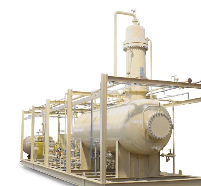


Utilising THIOLEX technology, the BB stream is treated with regenerated (lean) caustic to extract acidic sulfur components. The REGEN ULS regenerates the spent caustic from the THIOLEX unit while removing almost all DSO.
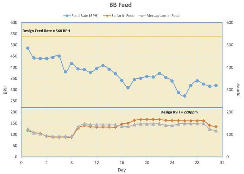
Figure 2 shows the actual BB feed throughput in bbl/hr, total sulfur and total extractable mercaptans in ppmw in the feed. Even as fl ow was reduced, feed sulfur remained high in both streams.
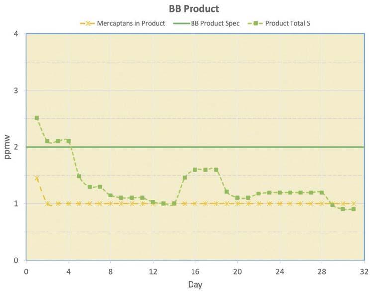
Figure 3 shows the results of both total product sulfur and mercaptans compared to the design BB product specifi cation (the solid green line). For a month of normal operation, the impurities in the feed BB compared to the design case, the BB unit was under the total S product specifi cation of 2 ppmw. Table 1 shows the design feed throughput and impurities compared with actual feed throughput and impurities. As can be seen from the results, the stream successfully met all product specifi cations.
Delivering financial, operational and environmental benefits
Figure 2. Actual butane/butylene (BB) throughput, total sulfur and total mercaptans as the impurities in the feed.
Figure 3. Actual BB mercaptans and total sulfur in the product vs the product specifications for mercaptans and DSO. Cost effective and efficient
Merichem’s combined THIOLEX and REGEN ULS solution is less expensive than hydrotreating or once-through caustic treating with no regeneration. Compared to a typical REGEN, the REGEN ULS costs 10 – 15% more, but yields a much lower total sulfur hydrocarbon product.
The FIBER-FILM Contactor enables more surface area for the mass transfer of hydrocarbon impurities with caustic soda. Due to this effi cient mass transfer rate and low energy mixing, residence time is signifi cantly reduced, and emulsions and caustic soda carry-over are minimised.
Environmentally sound
Regenerating and recycling caustic soda not only lowers OPEX but also helps protect the environment. Without a regeneration unit, spent caustic must be processed internally or manifested and shipped as hazardous waste to a third-party waste handler. With a regeneration unit there is still some caustic that needs to be removed; however, the volume shipped out is much lower than it would be if the unit was a single pass with no regeneration unit. Alternative technologies such as hydrotreating are also signifi cantly more energy intensive.
Net results
A determined commitment to teamwork by both parties resulted in the refi nery in this case meeting its requirements for manufacturing 10 ppm sulfur product to meet the EPA Tier-3 regulations for gasoline. Table 1. Feed and product specifications (ppmw) and unit throughput The THIOLEX/REGEN ULS technology provided a reduction in the sum of mercaptans and disulfi de oil as sulfur to lower than 2 ppmw in the product stream along BB (design) BB (actual) with ease of operation. Feed totul sulfur 240 170 The unit can handle turndown scenarios and has Feed RSH 220 150 handled up to 20% C5+ material in the feed, with the only Feed non-extractable sulfur 16 20 impact being increased caustic consumption. On a Product total sulfur 2 day-to-day basis, operating involvement is minimal. Most of the operation is monitoring levels, pressures, fl ows, and Product RSH + DSO 2 1 temperatures with occasional caustic batching and catalyst Throughput (bbl/hr) 540 400 additions.


Robert P. Saunderson, Air Products, USA, explores how to find the right combination of LNG subcooling and end-flash.


In a natural gas liquefaction (LNG) facility, the amount of subcooling performed on the LNG and the quantity of end-fl ash vapour produced affects the investment in liquefaction equipment and refrigeration power. Since there is limited fl exibility in some instances and a wider array of possibilities in others, it is important to understand each of the available options. This will allow the right combination of LNG subcooling and end-fl ash to be selected based on all factors infl uencing the decision when using an AP-C3MRTM or AP-DMRTM LNG process.
Fully-subcooled liquefaction process
While liquefaction of natural gas is performed at high pressure (55 – 75 bara), the LNG storage tank is operated just above atmospheric pressure. To prevent fl ash in the LNG storage tank due to adiabatic pressure reduction from liquefaction pressure to tank pressure, LNG must be subcooled to approximately -161.5°C to -163°C in the main cryogenic heat exchanger (MCHE). This is known as a ‘fully-subcooled’ liquefaction process.
The feed gas to liquefaction in a fully-subcooled process must have ≤ 1 mole% nitrogen content to meet the standard LNG product specifi cation in the storage tank. Although this process produces no adiabatic end-fl ash or tank-fl ash, vapour is formed in the LNG storage tank due to heat leak and pump work in the LNG piping to storage and heat leak into the storage tank itself. This vapour is known as storage tank boil-off gas (BOG). The BOG, which is displaced by rising liquid level in the tank from incoming product, must be withdrawn from the storage tank to avoid an overpressure. Although nitrogen will preferentially migrate to the vapour phase, there is not enough BOG formed to appreciably lower the nitrogen content of the LNG. Since BOG is mostly methane (usually 84 – 97% methane, 3 – 16% nitrogen, and ≤ 125 ppm ethane), it is often compressed and used as fuel. In a fully-subcooled process, the nitrogen concentration in the BOG and the MCHE exit temperature strongly correlate with the nitrogen content of the natural gas feed as shown in Figure 1. Since the fully-subcooled process generates a relatively small amount of BOG that can be used as fuel, this process is a good fi t when the refrigerant compressors in the liquefaction unit are driven by motors drawing power from the local electric grid. In facilities where the


