13 minute read
Hot and cold recycle control


PF control application in a cascade control scheme. The control applications would communicate among each other to provide integrated control and protection of the entire train.
Advanced GT closed-loop to power turbine speed (NPT) minimum governor
After passing all start permissives, a two-shaft GT enters the startup sequence where it passes through two phases: Open-loop control: during the initial phase of a startup, the fuel demand is calculated using open-loop control techniques. This phase typically consists of ignition, flameproof, fuel control valve (FCV) warmup and FCV ramp sub-phases. Closed-loop control: after the open-loop control phase, the GT applies closed-loop control to ramp up high-pressure rotor speed (NHP) and then NPT. This phase depends on the startup goal and typically consists of NHP warmup, NHP acceleration, NHP loading, NPT warmup, NPT control, and NPT loading sub-phases.
The startup sequence quickly ramps the local SP through NHP and NPT pre-confi gured critical zones. This minimises the turbine’s operating time at these critical speeds.
For a two-shaft GT, normally either NPT or NHP loop is selected as the main control loop PV, thus determining which process variable will be controlled when no limiting conditions exist. That loop then calculates a proportional integral derivative (PID) bidirectional response to deviations of its PV from a local or remote SP. The remaining loops operate as limiting control loops that protect the GT against excessive speeds such as NPT, pressures such as compressor discharge pressure (CDP), temperatures such as exhaust gas temperature (EGT), fl ameout, critical speed operation, and axial compressor surge. If only one limiting loop is active, its PID response is selected. If multiple limits are exceeded, the GT controller selects the high limiting loop with the lowest or most-negative proportional plus derivative response and adds the lowest or most-negative differential integral from any active loop. For safe operation, limiting loops have more priority than the main PV control loop.
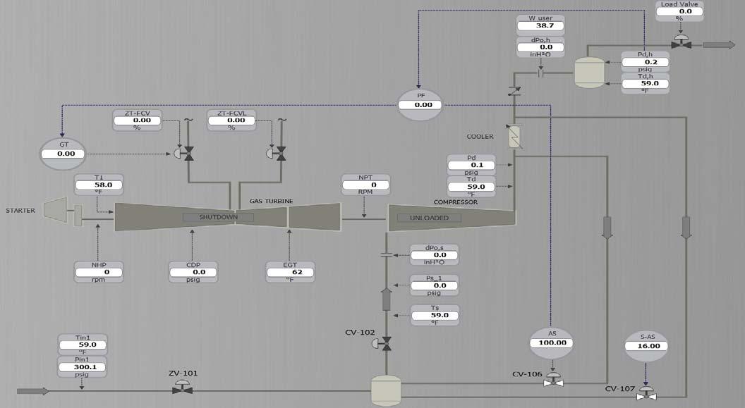
Figure 1. Train in shutdown.

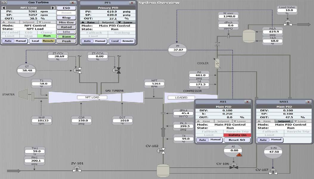
Figure 2. Train start.
EGT limiting loop
The EGT is the temperature at the GG (gas generator) discharge. In multi-shaft applications, EGT is also called T4 and the power turbine exhaust temperature is referred to as T6. While the combustion chamber temperature (T3) imposes a more direct limitation on the turbine’s power output than EGT does, the latter is frequently the only one of the two that is measured. The combustion temperature is then indirectly limited
by variable EGT limits, in which case the EGT acronym is an implied reference to T3.
Typically, the high-limiting threshold for EGT is defi ned as a function of CDP. There is no provision for EGT low limiting.
On the other side, the effi ciency of the GT is also affected by T1; the more ambient the temperature is, the less turbine’s power output.
Cold recycle control
A cold recycle loop serves to prevent heat buildup within a process. The most common process application for an SAS controller is to control the fl ow through a cold recycle loop in a network of parallel compressors. However, there are other applications for SAS, including serving more than one compressor section simultaneously, and when sustained recycling is necessary. Therefore, it is often desirable to use this cold recycle loop fi rst where possible.
The additional cold recycle loop is typically controlled using an SAS control application, whereas the non-cooled (or hot) recycle loop is controlled by an AS controller.
The AS controller calculates an ‘S’ value (the position of the compressor operating point [OP] relative to the surge control line [SCL]) for its compressor. The SAS controller receives that ‘S’ value and calculates a corresponding deviation. By setting the deviation SP within the SAS controller, the operator can control which recycle loop (hot or cold) will react fi rst to protect the compressor from a surge condition: When the SAS deviation SP is given a value greater than zero, the SAS valve will begin to open before the AS valve.
This is the typical setting except in the case of rapid or large disturbances. When the SAS deviation SP is given a value less than zero, the SAS valve will begin to open after the AS valve. When the SAS deviation SP is given a value equal to zero, both AS and SAS valves will begin to open at the same time.
Like in the AS controller, an RTL is also confi gured within the SAS controller, relative to the deviation SP. The RTL(SAS) will move with any changes made to the deviation SP within the SAS controller.
For a well-tuned control system, using the cold recycle loop should provide enough fl ow to prevent surge, reducing the need for the AS controller to open its hot recycle valve. At the same time, the hot recycle loop is still required, especially during large process disturbances.
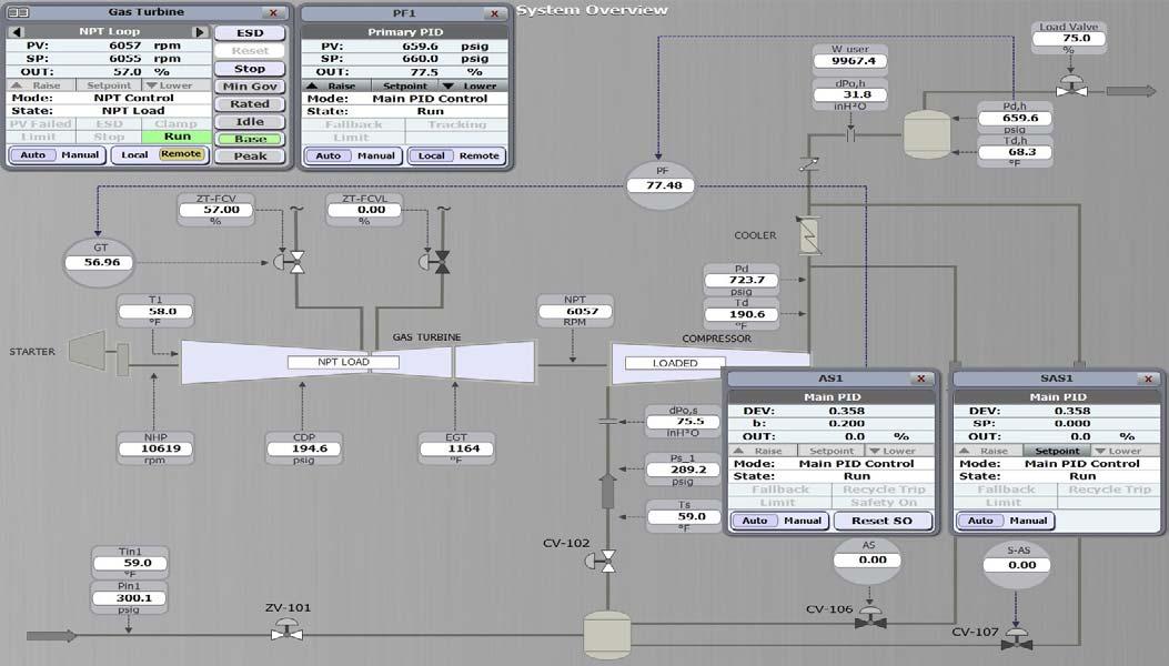
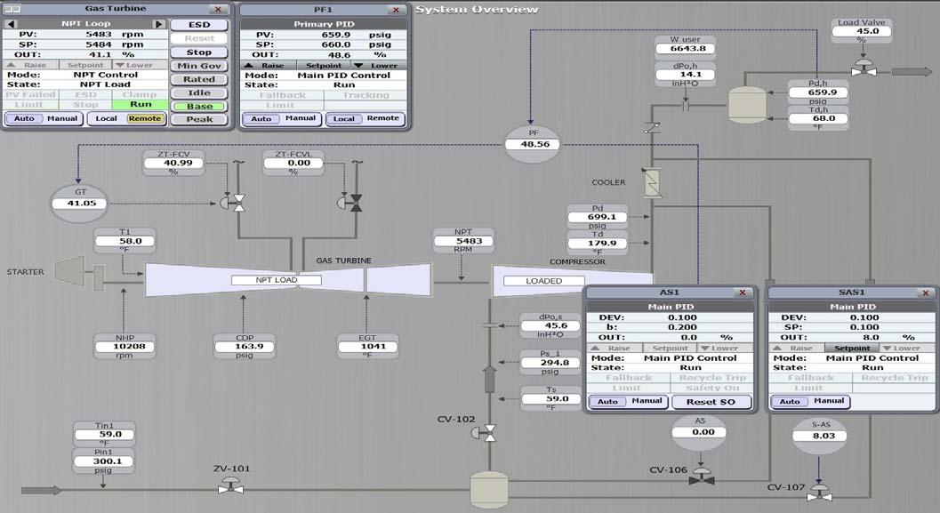
Figure 3. Compressor loading.
Figure 4. Cold recycle loop.
Simulation demonstration
The process to be simulated is a gas-pumping station comprised of a two-shaft GT driving a process centrifugal compressor, as shown in Figure 1. The compressor includes two recycle loops: one upstream of the discharge cooler (the hot loop), controlled by an AS controller, and one
downstream of the cooler (the cold loop), controlled by an SAS fl ow to protect the compressor from surge, with no action controller. The PF is set up to send its output as a remote SP to from AS1 control valve (CV-106) as shown in Figure 4. After the GT controller. The LC was custom designed to sequence the stability, the OP of the compressor settles on SCL(SAS) at a GT startup, pressurise the gas compression station, and purge deviation of the OP from the SCL (DEV) of 0.100. the compressor before it goes online with the process. Figure 5 shows a hot recycle loop: imagine that the load
Figure 1 shows a train start. Initially the GT controller is in valve is opened back to 75%, stability is waited for, and the ‘shutdown’ and ‘local’, PF1 is in ‘tracking’, AS1 is in ‘shutdown’ deviation SP on the SAS1 controller is then set to -0.100. This and SAS1 is in ‘purge’. The GT controller must be ‘reset’ before will place the SCL(SAS) to the left of SCL(AS). If the load valve the turbine can be started. After ‘reset’ is inserted, and after is closed by 30% (from 75 to 45%) to induce another surge passing all start permissives, the GT controller will change its protection response, the AS1 control valve (CV-106) will open state from ‘shutdown’ to ‘ready to run’. The turbine can then and sustain a recycle fl ow to protect the compressor from be started by initiating a ‘start’ command. Once started, the surge, with no action from SAS1 control valve (CV-107) as train will reach the minimum governor speed (start goal) of shown in Figure 5. After stability, the OP of the compressor 4525 rpm NPT as shown in Figure 2. settles on SCL(AS) at a DEV of 0.000.
In this train, the turbine can be started and run on either During closed-loop control, imagine the load valve is gaseous or liquid fuel. Only all-gas or all-liquid (100%) settings opened back to 75% and the deviation SP adjusted in the SAS1 are possible for startup. Initially the selection is set to ‘gas’ via controller to 0.100 again. If the knockout drum SP is reduced ZT-FCV (position transmitter-fuel control valve). With the to 620 psig, the speed of the GT will reduce due to the compressor loaded and stable, it can be switched to ‘liquid’ cascade control from PF1 to satisfy the new process via ZT-FCVL (position transmitter-fuel control valve liquid). requirements. During closed-loop control:
Figure 3 shows compressor loading. The compressor can The GT controller will manipulate the selected FCV using be loaded by asserting the ‘load’ command and allowing the PID control to satisfy the remote SP received from PF1. turbine to reach stability at a knockout drum pressure of The train’s speed is maintained between minimum 660 psig. Putting the GT controller in ‘remote’ will enable the (4525 rpm) and maximum (6500 rpm) NPT governor speeds. PF1 controller to send its output to the GT controller as a remote SP. Both AS1 and SAS1 controllers will start closing their recycle valves, as shown in Figure 3. If the GT controller is not in ‘remote’, the compressor will load at the minimum governor speed (4525 rpm). If in ‘remote’, the PF1 controller will send its output as a remote SP to the GT controller. This results in an increasing speed as the PF1 controller achieves a knockout drum Figure 5. Hot recycle loop. pressure SP of 660 psig.
Figure 4 shows a cold recycle loop. Imagine that the deviation SP in the SAS1 controller is set to 0.100, and the load valve is closed by 30% (from 75 to 45%) to induce a surge protection response from the controllers. Note that SAS1 control valve (CV-107) opens Figure 6. The reaction to the driven centrifugal compressor surge and the train stability after centrifugal compressor surge.and sustains a recycle

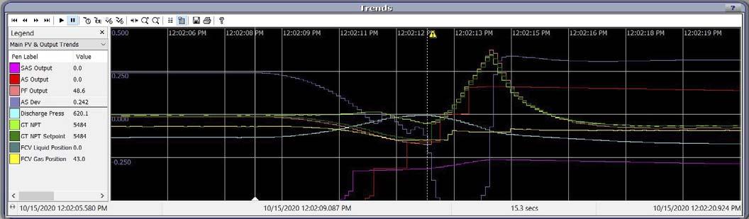
Figure 6 shows the reaction to the driven centrifugal compressor surge. Imagine a centrifugal compressor surge event is induced by closing the load valve from 75% to 10% (increasing the process resistance) as shown in Figure 6. The SAS1 control valve will open fi rst based on its PI and then recycle trip (RT) tunings, as shown in the pink trend, followed by AS1 control valve (PI and RT actions too), as shown in the red trend, to protect the compressor from another surge event.
Figure 6 also shows train stability after centrifugal compressor surge. The train stabilised after one surge cycle on SCL(SAS) as shown in Figure 7. Knockout drum pressure is maintained at 620 psig with SAS control valve open only. AS1 control valve closed automatically since the DEV is positive. The operator would typically rectify the load valve and then reset the surge count to eliminate recycling.
Figure 8 shows EGT limiting. Typically, the average EGT is calculated by the GT controller, then it is used as the EGT PV. Imagine that everything is returned to normal by setting the load valve position at 75%, and the knockout drum SP is then increased from 620 psig to 720 psig (via PF-1). EGT limiting at 1200°F will be activated, preventing the train from increasing its speed further as shown in Figure 8. Process requirement cannot be maintained due to EGT limiting loop taking control of ZT-FCV. Since the GT controller is in limit, the PF1 controller is in ‘tracking’. This mode of operation implies the unit is running ‘fl at-out, full power’.
To safely stop the train, we can fi rst ‘unload’ the compressor, put the GT controller in ‘local’, and then give the ‘stop’ command to the GT controller. The stop sequence shuts the GT down gradually. Typically, the selected SP (either the cooldown or the minimum governor speed) is then held constant until the cooldown timer expires, thus allowing the turbine to cool down, then closes the FCV completely, as shown in Figure 1.
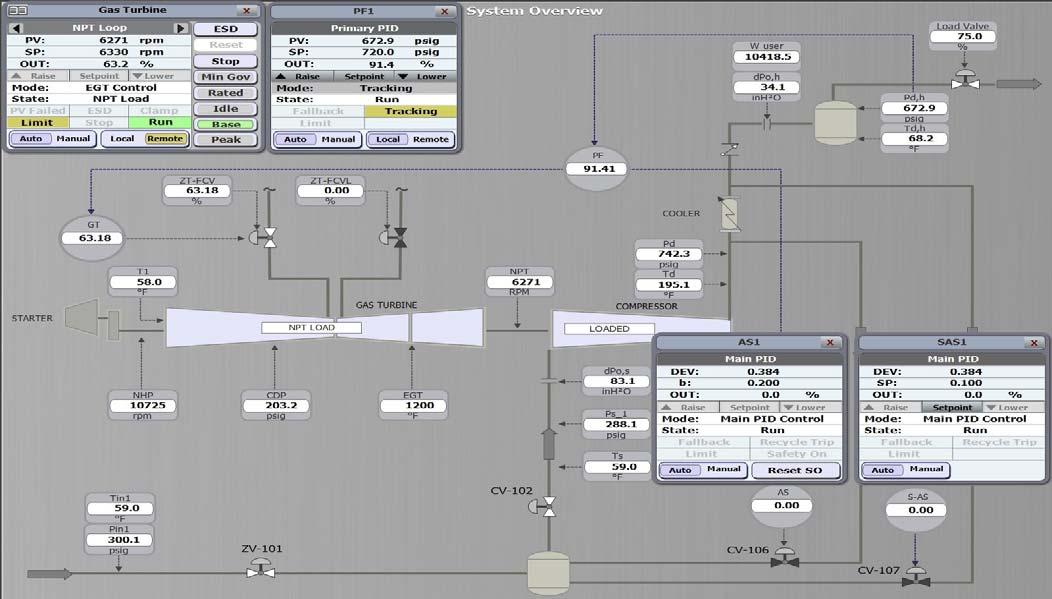
Figure 7. Train stability.
Figure 8. EGT limiting.
Summary
Various loops govern the operation of the GT. In order to achieve integrated control of a GT-driven rotating equipment train, various CCC controllers were developed. A well-tuned GT-driven centrifugal compressor train should absorb upsets, changes in the process conditions, as well as load demand requirements. At the same time, the control system should be designed to apply various limit loops to protect the train. Other application-specifi c features such as overspeed protection, fl ameout and over-fuelling protection, and fallback strategies can be applied as needed.
Reference
1. Compressor Controls Corporation; UM5525, UM6414, UM6421 Reference Manuals, (March 2019).


Hydrocarbon Engineering talks to some of the catalyst industry’s foremost experts, who share their insights on the latest developments in the downstream catalyst and precious metals market.
Dr Detlef Ruff, Senior Vice President, Process Catalyst, BASF
Dr Detlef Ruff joined BASF in 1995 as a Research and Development Chemist. In his career at BASF, spanning more than two decades, Dr Ruff has held various positions in operations, planning, strategy, marketing and business with increasing responsibilities. He served as Executive Assistant to the Chairman of the Board of BASF from 2001 to 2003, followed by a fi ve-year delegation to Singapore as a Regional Marketing Director for Agricultural Products. Back in Ludwigshafen, Germany, Dr Ruff served as Vice President Global Strategy and Product Development for the Dispersions and Pigments business. In 2013, he took over global responsibility for the Process Catalysts and Technologies business at BASF Corp. in Iselin, New Jersey, US, as Senior Vice President. He currently serves as Senior Vice President, Process Catalysts, at BASF SE in Ludwigshafen and as Chairman of the Supervisory Board of BASF Catalysts GmbH, Hannover, Germany.

Lars Skyum, Senior Vice President, Clean Fuels and Chemicals Catalysts, Haldor Topsoe A/S
Lars Skyum has been working for Haldor Topsoe since 1995. In this time he has worked in the catalyst business, where he has had various positions in technical service, sales and strategic marketing. In 2012 he was appointed Vice President for hydprocesssing catalysts, and since 2020 he worked as Senior Vice President, Clean Fuels and Chemicals Catalysts, being responsible for Topsoe’s hydroprocessing and syngas catalyst business.

Rajesh Gattupalli, Vice President and General Manager (VPGM), Honeywell UOP
Rajesh Gattupalli is VPGM for Petrochemicals in UOP’s Lifecycle Solutions & Technologies business. He joined UOP in 2008, holding a number of roles in R&D, product line management and marketing. He most recently served as Senior Business Leader for alkylation technologies.

Dr Meritxell Vila, General Manager, MERYT Catalysts & Innovation
Dr Meritxell Vila began her professional life working for Repsol at the Research Centre in Cartagena, Spain, studying ion exchange resin catalysts for the ETBE/MTBE synthesis. After spending several years on process development at the pilot plant units of the research centre, focusing on diesel hydrotreatment and gasoline hydrodesulfurisation, she moved to the Repsol Cartagena refi nery to work at the quality control laboratory and the process department in the Lubricants and Hydrotreatment divisions. She was the Catalysts Coordinator of the refi nery for several years, including the C-10 large project to double Cartagena refi nery’s capacity. In 2011, Meritxell joined IMCD Spain, moving into chemicals distribution, where she worked as the Product and Project Manager, representing the major international catalyst and adsorbent manufacturers in the Spanish and Portuguese markets. In 2016, Meritxell started her own company, MERYT Catalysts & Innovation, to help customers to optimise their processes by reducing costs in catalysts, adsorbents, and chemical products. The company also develops innovative technologies to save energy and reduce emissions.

Bradford Cook, Vice President – Sales and Marketing, Sabin Metal Corp. Brad joined Sabin Metal Corp. in late 2012 and was named Vice President of Sales and Marketing in January 2015. He has over 35 years’ experience in the precious metals industry. Brad has been a member of the International Precious Metals Institute since 1999, has served on its Board since 2007, and was the President of the Institute for the 2012 – 2013 term. He has written numerous articles for industry publications and delivers presentations on precious metals around the world.


