11 minute read
End-fl ash is totally cool
End-flash liquefaction process
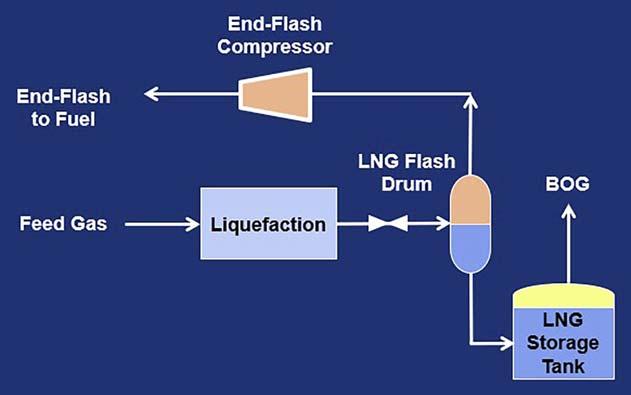
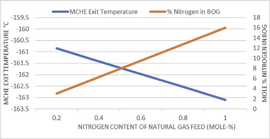
When the feed gas to liquefaction has > 1% nitrogen content, the fully-subcooled and fl ash-in-tank processes are not acceptable options, since nitrogen must be expelled from the LNG prior to entering the storage tank. Instead, an LNG fl ash drum is included downstream of the MCHE allowing the MCHE exit temperature to be warmer, typically between -145°C and -151°C depending on plant fuel requirements, since a warmer exit temperature creates Figure 1. MCHE exit temperature and BOG nitrogen content as a function more fl ash vapour. This is known as an of nitrogen content in the natural gas feed. ‘end-fl ash’ liquefaction process and is depicted in Figure 2. The LNG fl ash drum usually operates at 1.25 bara. The vapour generated in the LNG fl ash drum, which has a higher nitrogen content than BOG, is typically compressed and sent to the fuel header. The MCHE exit temperature is infl uenced mainly by fuel demand and feed gas nitrogen content, with a higher fuel demand or greater feed gas nitrogen content leading to a warmer MCHE exit temperature. When using an LNG fl ash drum, 90 – 95% of the fuel requirement for the gas turbines driving the refrigerant compressors and other power generators can be drawn from the end-fl ash and BOG while a buffer of about 5 – 10% of the fuel is typically drawn upstream of liquefaction. Figure 2. Schematic of the ‘end-flash’ liquefaction process.
refrigerant compressors are driven by gas turbines, the BOG provides only a small fraction of their fuel requirement, so typically the remaining fuel is drawn from feed gas upstream of liquefaction. Generally, the feed pressure is greater than the fuel header pressure, so no additional compression is needed. Fuel drawn upstream of the liquefaction unit will contain any LPGs that were not removed in an upstream NGL extraction unit.
Flash-in-tank liquefaction process
Since most LNG storage tanks can accommodate additional vapour, some facilities elect to operate with adiabatic tank-fl ash gas. When adiabatic fl ash gas in the storage tank becomes part of the BOG, the LNG temperature at the MCHE exit is typically -155°C to -156°C. This is known as a ‘fl ash-in-tank’ liquefaction process. Although a lower percentage of the feed gas becomes net LNG compared to the fully-subcooled process, the refrigeration power required per an identical amount of LNG in storage (specifi c refrigeration power) can be 6 – 7% lower for the fl ash-in-tank liquefaction process. Generally, the adiabatic fl ash portion of the BOG is 65 – 75 mass% of the total vapour generated in the storage tank. This process removes a larger amount of nitrogen from the LNG. Typical tank designs can accommodate the increased vapour fl ow when the feed gas has ≤ 1 mole% nitrogen.
At higher feed gas nitrogen content an LNG fl ash drum may not be suffi cient to expel enough nitrogen to meet the ≤ 1 mole% nitrogen specifi cation in the LNG product. Since nitrogen removal is a broad topic with too many options to cover here, please consult the reference listed at the end of this article for more information.
End-flash liquefaction process with recycle
To further reduce the specifi c refrigeration power, the MCHE exit temperature can be warmed to -140°C to -146°C if a portion of the end-fl ash is compressed and recycled to rejoin the natural gas feed at the liquefaction unit inlet. This is known as an ‘end-fl ash with recycle’ liquefaction process and is depicted in Figure 3.
Recycling end-fl ash vapour creates a higher nitrogen content in the LNG exiting the MCHE, meaning that it is important to be aware of the threshold where a nitrogen removal scheme becomes necessary instead of an LNG fl ash drum due to the additional cost of this unit.
Advantages of end-flash liquefaction processes
Although a larger fraction of feed gas is diverted to end-fl ash gas in the end-fl ash processes, the refrigeration required per unit of net LNG in the storage tank decreases as the MCHE exit temperature becomes warmer. Reducing MCHE duty by
warming the MCHE cold-end exit temperature decreases the amount of refrigeration required at the coldest temperatures. A colder MCHE exit temperature is achieved mainly by increasing the nitrogen content of the mixed refrigerant (MR). The rest of the MR is hydrocarbon based: methane, ethane, and propane. Since nitrogen is the MR component with the highest heat capacity ratio, it is the most power intensive to compress. End-fl ash processes redistribute duty from the coldest section of the process to the less energy intensive warmer parts, thereby reducing refrigeration compressor power consumption for the same net LNG production.
Provided there is a use for the end-fl ash and BOG, typically as fuel, it is favourable from a refrigeration perspective to make the MCHE exit temperature as warm as possible. This is most advantageous when trying to keep the power requirement for the refrigeration compressors within the power available from the installed gas turbines that drive these compressors. As the MCHE exit temperature is warmed, power is diverted from the refrigerant compressors to end-fl ash compression. The diversion of power from refrigerant compression to end-fl ash compression is approximately power neutral from an overall liquefaction unit perspective. The end-fl ash compressor and end-fl ash recycle compressor are typically driven by electric motors.
The end-flash exchanger
The cold temperature vapour from the LNG fl ash drum is approximately -161°C to -162°C and can be used to provide refrigeration to a portion of the feed gas drawn at high pressure from just upstream of the MCHE warm-end inlet at about -30°C. The heat exchanger used for this refrigeration recovery is called an end-fl ash exchanger and is depicted in Figure 4.
An end-fl ash exchanger covers a similar temperature range to the MCHE and has a duty that is about 2% of the total MCHE duty. The benefi t of end-fl ash processes and the end-fl ash exchanger is most apparent when it can be used to increase LNG production by diverting power out of the refrigerant compressors and duty out of the MCHE and other liquefaction unit heat exchangers. Although it is possible to route the cold -161°C vapour from the LNG fl ash drum directly to compression instead of recovering its refrigeration, using this vapour as refrigerant in an end-fl ash exchanger and warming it to approximately -30°C prior to compression can increase LNG production by 1.5 – 2%.
Typically, the end-fl ash system consists of the end-fl ash exchanger and a separate LNG fl ash drum. There are several types of heat exchangers that have been used in end-fl ash service. The most common involve an array of parallel brazed or printed-circuit aluminium heat exchangers mounted inside in an insulated steel-framed structure. The other type is a coil wound exchanger (CWHE). The end-fl ash exchanger can experience signifi cant thermal stress due to the very wide temperature range it covers (-30°C to -160°C). The MCHE, which covers a similar temperature range, has mostly been a CWHE due to its mechanical tolerance for high thermal stress. The LNG fl ash drum can be incorporated into the sump of the CWHE shell as shown in Figure 5, thereby reducing overall equipment count and plot space requirements.
Externally connected piping and platforms are supported from the vessel without the requirement for an additional structure. This design also eliminates low pressure cryogenic piping between the LNG fl ash drum and end-fl ash exchanger, which decreases pressure drop to the end-fl ash compressor suction.
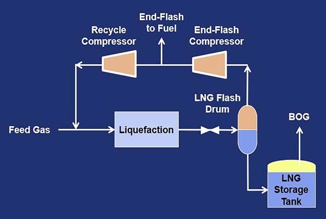
Figure 3. Schematic of the ‘end-flash with recycle’ liquefaction process.
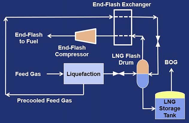
Figure 4. Schematic of the ‘end-flash’ liquefaction process including end flash exchanger.
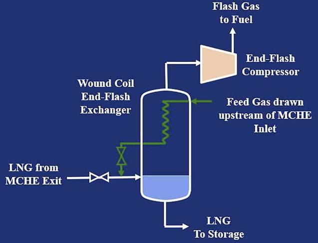
Figure 5. Schematic of the wound coil end-flash exchanger.
Table 1. Debottlenecking by converting to end-flash processes
Liquefaction process MCHE exit temperature
(˚C) Net LNG in storage tank
(% of base case) Refrigeration compressor gas power
(% of base case) End-flash compressor (+ recycle compressor) gas power
(% of refrigeration compressor gas power)
Flash-in-tank (base case) End-flash, no recycle End-flash, with recycle -156 100% (base case) 100% (base case) 0%
-151 103.5% 100% 3.5%
-146 107.5% 100% 7.5%
Case study recommendations
Case study: using end-flash liquefaction processes for debottlenecking
When the feed gas to liquefaction has ≤ 1 mole% nitrogen, the prevailing tendency is to design the liquefaction unit using a fully-subcooled or fl ash-in-tank liquefaction process to avoid the capital cost of the end-fl ash equipment – separator, exchanger, and compressor(s). However, adding this equipment and converting to an end-fl ash process (with or without end-fl ash recycle) can represent a debottlenecking opportunity to increase LNG production. Table 1 shows an example of how conversion from a fl ash-in-tank process to an end-fl ash or end-fl ash with recycle process can increase net LNG in storage (after BOG is deducted) by adding power for end-fl ash and recycle compression without increasing refrigeration power consumption. This example is applicable when gas turbines are used to drive the refrigerant compressors. All the end-fl ash vapour is used as fuel unless it is recycled to join the feed gas at the liquefaction inlet.
For an LNG facility with ≤ 1 mole% nitrogen in the feed gas, it is best to evaluate liquefaction processes with and without end-fl ash during the design phase. Since gas turbines have mostly discrete power generating capability, the desired LNG production capacity may not fi t well with any reasonable combination of gas turbines selected to drive the refrigerant compressors. The power of certain gas turbine drivers can be augmented by electric starter/helper motors, but in some instances the addition of an end-fl ash system may be the best option to maximise LNG production capacity.
Reference
1. OTT, C. M., ROBERTS, M. J., TRAUTMANN S. R., and
KRISHNAMURTHY, G., ‘State-Of-The-Art Nitrogen Removal for Natural
Gas Liquefaction: New Solutions to Meet Market Needs’, Gastech (2014).
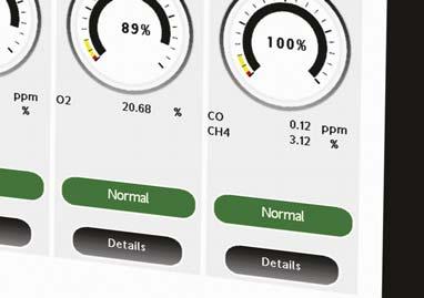
NEO Monitors’LaserInspect™ CIMO4
ALL-IN-ONE CONTROL PANEL FOR THE LASERGAS™ FAMILY
LaserInspectTM CIMO4
Expandable with up to 4 analyzers connected to one interface
Span / Validation reading
Touch screen with easy and intuitive navigation
Easy way to check analyzer status


LaserInspectTM


Nicola Curtis, Rotork, UK, explains how flow control supports safety and reliability in the LNG industry.

The growth of the worldwide LNG industry shows little sign of slowing down. Instead, the production and use of LNG is a clear area of growth, and McKinsey forecast that it is due to grow 3.6% every year up to 2035.1 The use of LNG is increasing in importance as the demand for gas grows and large quantities of gas are processed and transported around the world. A key benefi t of LNG is its ability to be moved around the world on specialist carrier ships or cryogenic tankers, providing easy access for customers. Once processed into LNG, the resulting liquid is 600 times smaller than its natural gaseous state. This makes transportation more economical than if the original natural gas was transported. Once regasifi ed, LNG is used as a fuel source, increasingly as commercial transportation fuel and as a power source for domestic and industrial use. It can also fairly claim green credentials when used as a fuel source compared with other fossil fuel types such as oil and coal, as it releases reduced emissions into the atmosphere.
Despite the high quantity of natural gas available, it is often found in remote locations that are hard to access. This means that there are many complex processes involved at all stages of LNG production. The LNG supply chain is complex and technical, involving extraction and liquefaction, shipment on special tankers, regasifi cation at import terminals, and distribution. Safe and reliable fl ow control has a key role within each part of the LNG industry process and specialist products and services are required.

How flow control products ensure safety within LNG
The extraction, processing and transport of LNG around the world must be completed in a safe and reliable way. Flow control plays a key role at every stage; from the extraction of gas, to its liquefaction, transport (both in pipelines and LNG carriers), regasifi cation, and distribution/onwards transportation. During the exploration and production stage, natural gas is extracted by producing wells in either ‘associated gas’ deposits or sometimes a by-product of oil production or extracted from coal seams as a non-associated gas. The gas is dried and processed before it is converted into LNG, removing condensates, impurities (such as carbon dioxide and hydrogen sulfi de), and water.


