10 minute read
The Mechanics Of Dynamic Ground Support

David Evans, DSI Underground Asia Pacifi c,
provides insight into the importance of the mechanics and mechanical response of ground support in underground hard-rock mining.
The ability for ground support elements to take the demands of sudden and severe service loads continues as an increasing requirement for geotechnical application within underground hard-rock mining. Large amounts of energy can suddenly release through the rock mass as stresses are redistributed and, at times, violent ground movement can occur. While the prevailing influences of geological stress fields may be mapped out, as well as local geotechnical considerations factored within mine design, there is an inherent degree of unpredictability in the way that stresses are released. Based upon the need to address such geotechnical demands, the mechanics of dynamic roof support remains an important area of continued study and research. While geotechnical design is the overarching discipline, the mechanics and mechanical


response of ground support elements are equally critical to understand and apply within this field.
Understanding mechanical energy
Energy is, of course, a universal term applied across multiple scientific disciplines. Under a common definition, energy is simply the ability of an item to conduct work. As defined under international standards, the unit of measurement for energy is the Joule – where one Joule is equal to the work conducted by one Newton of force acting over or through a distance of 1 m.
Of course, multiple forms of energy exist: thermal, mechanical, electrical and chemical, to name a few examples. Energy will exchange and transform across interrelated systems – consider the transformation of energy within an internal combustion engine, from chemical and thermal to mechanical energy. In this sense, energy can be stored, released, and transformed (while noting that losses or ineff iciencies will always occur under such transitions and transformations between systems). However, amidst this greater complexity, the unit of measurement for energy is held constant across all systems, under the simple definition of the Joule.
Focusing specifically on the context of energy within a mechanical system, a basic scenario is the tensile testing of a steel specimen. Tensile testing is a common method that is used to determine the mechanical properties of diff erent steel grades and to also assess the influence of geometric dimensions, as well as the elastic and plastic response through to failure. During testing, typically conducted under a constant rate of displacement or strain, tensile load is placed onto the steel sample. It will begin to elongate and the relationship between force and displacement is observed. This relationship is typically mapped out in a two-axis chart and, where all other test variables are held constant, it provides a relatively reliable outcome, particularly with standardised test specimens.
Once the relationship between force and displacement has been charted, the energy of deformation taken by the test piece can be determined. Mathematically, energy is calculated as the integral of force with respect to displacement, as the system moves from a first position to a second position. From an easier perspective, this equates to the calculated area under the force vs displacement curve. Think again of the definition of the Joule – put simply, a force acting over a distance. When testing, work is cumulatively conducted as force acts through displacement – measured as two related variables – and the total work is the accumulation of the area under the test curve, measured in Joules.
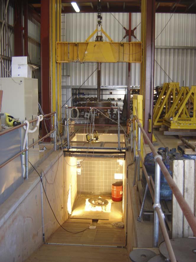
When measuring the dynamic energy of a roof bolt element, these same principles are applied, using force and displacement to calculate an energy value. However, the test method is greatly scaled up, to take the dimensions of the roof bolt element that is being assessed. Further to this, the rate of deformation of the test piece is significantly faster, by orders of magnitude, to simulate the speed of an underground rock burst event. Under more standard laboratory test procedures, loading is applied to a test piece over the order of minutes. However, in a dynamic test, the shock load is initiated in the order of 10 msec. and below. Again, the concept of energy transfer between systems applies – from stored energy within the rock mass to motion, and finally mechanical energy and work conducted by the ground support elements as they respond to the onset of load.
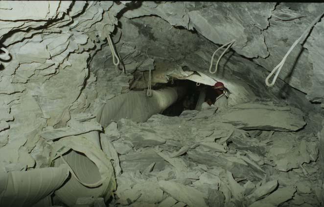
Figure 1. Damage to underground workings from a rock burst event. Source: ACG/David Ortlepp.
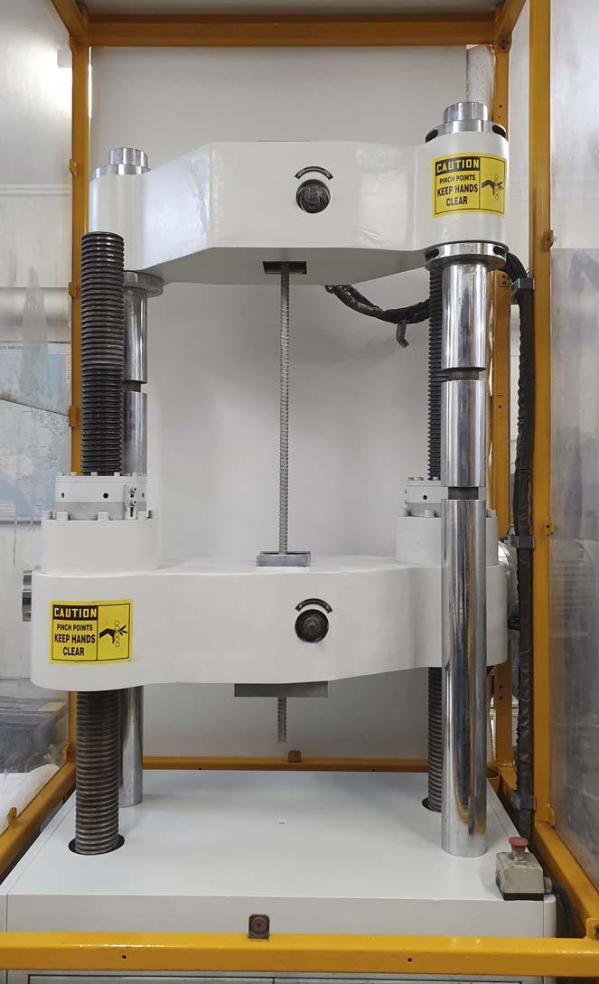
Figure 2. Typical laboratory tensile test arrangement.
The growth of global research
The dynamic testing of ground support elements is a highly specialised field requiring the development of large scale test facilities, well beyond the capabilities of standard mechanical test laboratories. Research into the dynamic performance of ground support elements has been a growing field of work, particularly over the last 20 years. At the forefront of this eff ort,
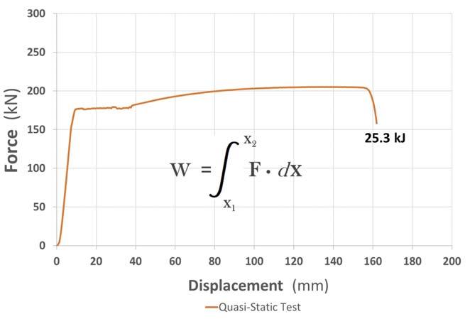
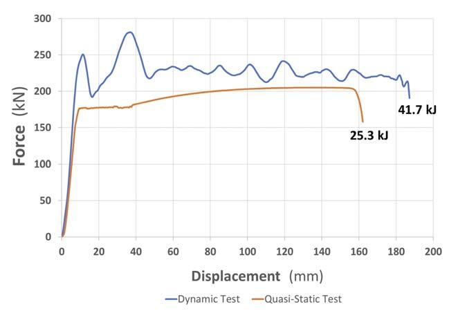
Figure 3. A quasi-static test curve (data from DSI Underground).
Figure 4. The WASM dynamic test facility.
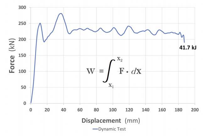
Figure 5. A dynamic test curve (data from DSI Underground). a number of more pre-eminent facilities have been established in association with industry and academic institutes – of particular note are WASM (Australia), CANMET (Canada), and the Central Mining Institute (Poland). In addition to these more recognised institutes, other test facilities have evolved more recently, typically in association with operators and suppliers within the underground hard-rock industry. While this global growth in research capability is certainly of note, it is not within the intent or scope of this brief article to provide an overview of these facilities in detail.
Energy is a summary indicator only
While calculated energy provides an overall summary indicator of dynamic performance, it is important to understand the actual load bearing response of the dynamic roof bolt element – that is, assessing the detail and shape of the test curve. The variables of force and displacement remain significant: peak loads must be known, as well as the total displacement until rupture or final failure of the test element. Also of importance is the initial rate of loading – that is, how quickly the loads are generated as displacement occurs. A stiff load bearing response indicates that the element takes load and begins to contain energy very early in the dynamic event, shown as a steeper gradient on the test curve. A soft load bearing response indicates that the element is much slower to take initial load, but may provide greater elongation properties. Ideally, a dynamic system will off er both properties – a stiff initial load response, followed by good elongation values at a sustained load.
Typical performance values
The selection and application of ground support elements, based on known performance parameters, is foundational within the field of geotechnical design. For underground hard-rock applications, primary bolting elements that bear peak loads within the range of 200 – 300 kN are commonly selected. In line with this load response, the desired dynamic displacement values are typically of the order of 150 – 200 mm. Within these ranges, as an approximation, corresponding energy values will be in the order of 30 kJ, up to more significant values exceeding 50 kJ. Displacements of 300 – 400 mm have been suggested at an extreme limit, although, at this level, surface support damage becomes a far more significant concern. Note that 20 kJ is commonly considered as the minimum recommended energy value for classification as a dynamic bolt. Of course, it is fully incumbent upon the geotechnical practitioner to determine the required ground support elements for their specific application – and all parameters should be considered, including: energy, force, and displacement. The final design of a dynamic ground support element should also meet the requirements of standard bolting applications.
Anchoring or slipping: generating the optimal response
Within the history of development, numerous dynamic bolt designs have emerged in an eff ort to best exploit the parameters of force and displacement. A primary consideration is the nature of anchoring within the ground at both the top and bottom of the bolt – and how anchoring ultimately relates to energy performance. The anchoring media is typically a polymeric resin or a cementitious grout – but this may be absent
where a mechanical expansion element is employed within the design to anchor the bolt. The anchoring method is critical to dynamic performance, and must be capable of transferring loads into the ground that exceed the mechanical strength of the bolt element. Essentially, the anchoring media must do the same work as the bolt in transmitting energy. The installed quality of the anchoring media is equally of significance and must be well mixed, cured, bonded, and repeatably installed for underground quality assurance.
If the upper and lower bolt ends are firmly anchored to the ground, the bolt element will be immediately and directly loaded when ground movement occurs. In this instance, a stiff load response occurs and the bolt element subsequently performs mechanically. Other approaches have been to permit the bolt to partially slip through an anchoring media, at reduced mechanical loads, but seeking to achieve greater displacement values. In this instance, a soft er response occurs and the bolting element is not loaded to its full mechanical performance. While displacement values may be increased, subsequent lower forces may detract from the total energy value.
Where the steel element is firmly anchored and employed to do the work under mechanical deformation, the load bearing response typically has greater repeatability. However, where the anchoring media is partially employed to provide the dynamic response under slipping with the steel element, this introduces a further variable that influences performance results. An additional concern with slipping modes is the progressive loss of the overall bolting horizon within the geotechnical application, particularly where fault lines and wedged blocks may exist. A line of argument is to firmly anchor the bolt and let the steel element do the work.
Deformation rates: Do mechanical properties actually vary?
As research has progressed, it has become evident that the rate of deformation and the speed of the test event will alter the shape of the mechanical test curve and the overall energy response of the steel element. As described earlier, the formal mechanical properties of steel grades are determined under heavily standardised laboratory procedures, using dimensionally regulated steel samples and conducted at low loading rates.
In vast contrast to this, dynamic loading events occur within the order of milliseconds – and the resultant mechanical properties diff er from those of standardised test outcomes. For directly equivalent specimens, even for the same steel grade, the same section type and the same gauge length, high speed dynamic testing will repeatably witness a diff erent energy outcome. Subsequently, for geotechnical designs within dynamic conditions, it is important to consider both the standardised mechanical properties derived from ‘quasi static’ laboratory tests, as well as the dynamic load bearing properties derived from high speed tests. It should be noted that the relationships within this aspect of the science are not perfectly known.
Continued research remains an imperative
A significant history of productive research exists within the field of dynamic ground support and this is well attested across the industry, yet much remains to explore. A large number of variables reside within this experimental work – test methods, material grades, geometric sections, bolt class and design, debonding design, anchoring media, primary and secondary support needs, as well as surface support considerations – and all of these variables cast an influence over decision making within geotechnical practice. This complexity is further compounded by steel grade suitability and supply availability, under domestic and global considerations.
When viewed within this broader context, but also understood at a more detailed level, it becomes clear that support for dynamic test work remains an imperative, to continue to build upon this body of knowledge that is increasingly essential for the safety and performance of the underground hard-rock industry.
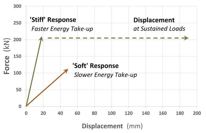
Figure 6. The gradient indicates load bearing and energy response.
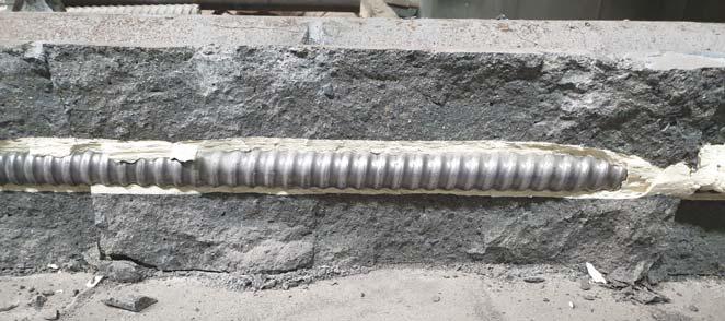
Figure 7. A cross sectioned sample of a resin anchored element following dynamic testing.
Figure 8. Overlayed test curves for two bolt elements of identical material type and free-length.
