
6 minute read
Problem avoidance in impellers


Hanxiang Jin, Rambabu Chundru, and Brian Pettinato, Elliott Group, USA, discuss fit capacity and torque predictions for impellers used in the LNG industry.


Centrifugal compressors play a critical role in the process industries, and that includes LNG. Within each compressor is a shaft with one or more impellers. Impellers are the essential components that perform work on the gas. Each impeller is driven by shaft torque and must be fixed to the shaft and not slip during operation. One method of transmitting torque is through a key and keyway, but this creates stress concentration as well as anisotropic shaft stiffness between the key and non-keyed bending planes. Furthermore, keyways add manufacturing cost. A better means of
torque transmission is by friction, whereby the impeller is shrunk onto the shaft like most coupling hubs. However, unlike a coupling hub, an impeller’s cross-section is highly non-uniform, and the centrifugal growth during operation is considerably more difficult to calculate; hence the torque carrying capacity is more difficult to determine.
In this article, a methodology is described for determining a conservative torque carrying capacity of the impellerto-shaft juncture based on reference FEA simulations. The method is based on the contact pressure equation of a coupling cylinder bore and shaft:1,2
Where E is the modulus of elasticity; δ is the static diametral interference fit rate between shaft and hub (δ=I/D); I is the diametal interference fit; D is the Nominal shaft diameter; δe is the loss of interference fit rate due to differential expansion of the impeller bore and shaft due to rotation; Pc is the contact pressure; Do is the nominal hub outside diameter; δb is the diametral bore growth scaled by shaft diameter due to rotation; δs is the diametral shaft growth scaled by shaft diameter due to rotation; and ω is the rotating speed.
Figure 1 demonstrates loss of fit for three different configurations. The bore growth for a simple cylinder can be obtained with elasticity equations without too much trouble, and the trend is always the same; the contact pressure decreases with speed and it does so uniformly. For a more complex geometry, such as a conical section, the contact pressure along the axial length does not decrease uniformly and may actually increase at certain locations due to the prying effect of the centrifugal growth. A complex geometry like an impeller typically requires finite element analysis (FEA) to determine the centrifugal growth.

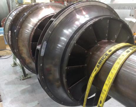
Figure 1. Bore deformation of interference fit under rotation.
Using FEA to determine centrifugal growth
There are two issues that need to be considered when computing the contact pressure for impellers. 1 – The loss of interference fit rate is non-uniform along the axial direction and is variant for different unique impellers. 2 – The nominal hub outside diameter of a cylinder is different than an impeller outer diameter, which is not uniform along the axial direction.
These two issues can be solved by performing a series of FEA simulations to determine an equivalent nominal diameter and a growth rate, as described in the equation below where the growth rate is a conservative fit of simulation data.
Where u is the impeller radial bore deformation, a function of the speed squared; N is the given shaft speed; δb is the impeller bore growth scaled by shaft diameter due to rotation; and D is the nominal shaft diameter. The function, (N, α), is a conservative fit of a standard set of simulation cases.
The contact force is obtained by integrating the contact pressure along the axial direction, and the torque capacity is obtained from the contact force, shaft diameter, and friction factor.
In order to validate this methodology, the procedure of predicting the impeller bore growth is examined first using a sample impeller. The rotor assembly with the selected impeller wheel is shown in Figure 2.
The geometry of the selected impeller has been imported and then modified to a sector model to reduce the FEA computation cost. The full circle
Figure 2. Rotor assembly of the selected impeller wheel.
Figure 3. Full circle geometry and contact results.
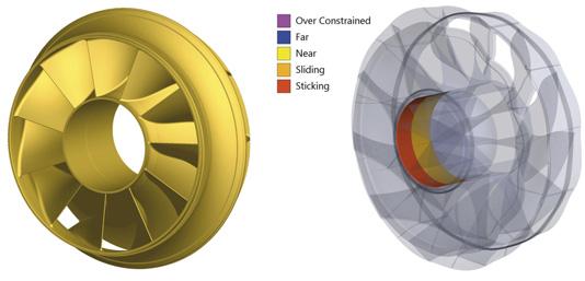
geometry and contact pressure status are shown in Figure 3.
In this case, the impeller had an initial interference fit rate of 0.5 mm/m and fit FEA simulation was performed on a standard set of cases to obtain the data used for the curve fit in the equation earlier. The impeller bore deformation data from the simulation was extracted and used to construct impeller bore growth under any working condition using the aforementioned equation. The predicted impeller deformation was then compared with the FEA simulations of several different rpm cases, and the results are shown in Figure 4. From Figure 4, one can observe that the 3000 rpm case and 4000 rpm case match the simulation results better than the 5000 rpm case. The reason for the divergence in the 5000 rpm case is that the impeller bore had already lost contact with the shaft in some of the area. The engineering approximation of the impeller bore deformation used in this article only needs to consider the interference fit area. As a result, at the contact lost area, the prediction is no longer valid and need not to be considered since it does not contribute to the contact force. The interference fit predicted by the method introduced in this study has been compared with the FEA simulations as well. The simulation results of the contact status and contact pressure are shown in Figure 5. The green colour on the left figures shows interference presence from predictions; the red colour means surface separation. In the FEA simulations, red colour to yellow colour means sticking behaviour changing to surface separation. The figure shows good conformance between the two sets of results. The obtained contact force and power carrying capacity using the methodology in this study is verified with the FEA simulations as well. During the verification process, simulations and predictions match well when there is full contact between the impeller bore and shaft. However, after the interference loss in some of the contact area, the torque capacity prediction would become conservative. The results are shown in Figure 6 for the standard frame size and scaled frame size.
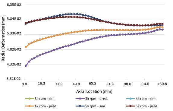
Figure 4. Impeller bore deformation, prediction vs simulation. 0.55 mm/m interference fit rate.
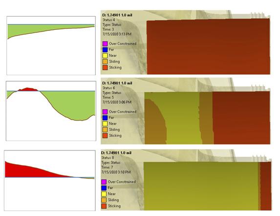
Figure 5. Contact state comparison. Prediction vs FEA simulation.
Conclusion
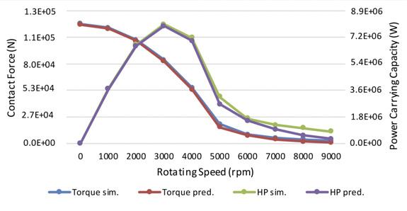
Figure 6. Allowable power comparison, prediction vs simulation. 0.5 mm/m interference fit rate. The method introduced in this study provides a fast way to evaluate the torque carrying capacity of the impeller-to-shaft juncture and visualising the interference.
The predictions are obtained based on pre-run reference FEA simulations.
In application, the results can be computed instantly, giving a huge advantage in estimation of impeller performance in various circumstances.
References
1. SHIGLEY and MISCHKE, Mechanical Engineering
Design, Fourth Edition, McGraw Hill, 1983, pp. 77. 2. ANSI/AGMA 9003-C17, Flexible Couplings – Keyless
Fits.


