10 minute read
LNG invasion phenomenon
David Gomez, Alberto Ramos, and Daniel Rivera, SacyrFluor, Spain, detail a case study of an LNG invasion phenomenon in carbon steel pipes, using dynamic simulation to study the kinetics.


After open rack vaporisers (ORV), an increase in fluid temperature allows for the pipe material to be changed from stainless steel (SS) to carbon steel (CS). Industry standards recommend performing a transient analysis to check the risk of cold propagation on piping downstream from the vaporiser. In the LNG terminal case of the study, the pipe specification break was very close to the equipment outlet. In order to verify the existing system, SacyrFluor (part of the Sacyr Group) studied the kinetics of an LNG invasion phenomenon in case of seawater failure in the ORVs by using a dynamic simulation. The dynamic simulation results were used to check the validity of the existing LNG terminal protections and, in case of inadequacy, to recommend the required modifications.
Introduction

The EN1473 standard (Installation and equipment for LNG design of onshore installations) states in section 8.1.2 Materials of Vaporisation of LNG, that “a transient analysis shall be performed in order to check the risk of cold propagation on piping downstream the vaporiser.” Additionally, in section E.2.6. Control/Safety of Specific Requirements for LNG Vaporisers, it states that “in case of low gas temperature” “the vaporiser shall be automatically isolated.” “Valve closure time should be set to prevent cold temperature extending over limits defined by thermal transient analysis.”
SacyrFluor was requested to perform this thermal transient analysis at an existing European LNG terminal. By using a dynamic process simulator which evaluates the kinetics of an LNG invasion phenomenon in ORVs in case of seawater failure, SacyrFluor checked the validity of the existing interlocks and recommended modifications if the existing interlocks were deemed to be inadequate.

Methodology
Dynamic simulation was performed with Aspen Hysys Dynamics v11. The thermodynamic package Peng Robinson with Lee-Kesler for enthalpy has been selected because, based on SacyrFluor’s experience in previous LNG projects, this was the option that best matched the results with field data.
ORV inlet conditions corresponded to high-pressure LNG header conditions. No change over time was considered in these conditions. Even when there was no high-pressure LNG flow as a result of the presence of protection, the pressure was assumed to remain constant in the pipes. Outlet conditions corresponded to the NG header. Pressure was


Figure 1. The Hysys model created for this dynamic simulation.
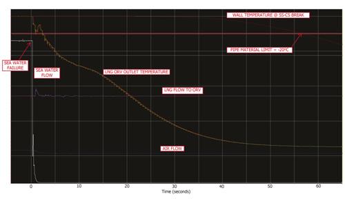
Figure 2. The ORV’s operating conditions profile over time in case of a seawater failure and without any protective measure.
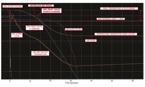
Figure 3. The ORV operating conditions profile over time in case of a seawater failure, and with an interlock closing a pneumatic on/off valve in the ORV inlet using a temperature transmitter located in the ORV outlet.


considered constant over time, but the temperature varied as the system progressed as a consequence of the upset.
In the dynamic simulation, the upset starts with the failure of seawater when it stops acting as the heating media and is replaced by natural draft with air. At this time the following actions were considered: Air flow is reduced from the required to get the normal duty to a reduced flow resulting from the natural draft.
Natural draft calculations were undertaken in order to estimate an air velocity. The tube outside heat transfer coefficient of ORVs is reduced to represent natural draft with air. The tube orientation was considered, since vertical tubes present a lower coefficient than horizontal ones. As a result of the heat transfer reduction in ORVs, vaporisation is stopped. Therefore, liquid LNG passes through the ORV without changing its liquid state. The tube inside heat transfer was calculated considering the forced convection of liquid. Once the interlocks are triggered, the LNG flow is stopped gradually following a ramp. The duration of the ramp corresponds with the final element action – i.e. the closure time of the valve (in case it acts on the feed valve), or the stopping time of the pumps due to the inertia (in case it acts on the high-pressure pumps). LNG is retained in the ORV and the temperature starts to increase due to the heat exchanged with the environment.
When LNG reaches the critical temperature, supercritical conditions develop, with the LNG behaving more like a gas than a liquid. The tube’s inside heat transfer is reduced. Tube inside heat transfer was calculated considering this phenomenon. The heat transfer in pipes downstream of the ORVs were calculated by Hysys according to the properties and conditions of the fluid inside them. A detailed model has been considered, taking into account the conduction of the pipe and inside and outside convection.
The condition that an interlock has to comply with to be considered adequate for an LNG invasion scenario in case of seawater failure, is to prevent any carbon steel section of the NG header outside ORVs from cooling down below its design temperature. In particular, the inlet wall temperature of the header at the break of stainless steel and carbon steel does not have to lower from -20˚C.
Results
The first working step was to simulate the seawater failure scenario without any protective measure. As expected, it was observed that once the seawater fails, evaporation stops and ORV outlet temperatures and wall temperature lowers quickly at the stainless steel-carbon steel (SS-CS) break. Pipe material operating limits are reached fast. The simulation confirmed that the installation of protective measures is required.
To properly design an interlock that protects the system, actions to be implemented and triggering actions were evaluated using the dynamic simulation. The following different interlock actions were evaluated and are outlined below.
Stop of primary pumps
In the terminal case of the study, stopping the primary pumps does not stop the flow to ORVs in a direct way nor
immediately. The stop of the LNG flow to ORVs is created indirectly after the loss of level in the recondenser which feeds LNG to the secondary pumps. Consequently, although LNG flow is stopped, cold LNG is retained inside the header and the cool down of the header continues. The minimum design temperature for carbon steel is still reached at the SS-CS break; therefore, this action is not an effective measure to protect this scenario.
Stop of high-pressure pumps
Stopping high-pressure pumps directly halts the LNG flow to the ORV. After the response time of the pump relay, LNG flow decreases gradually because of the remaining pump inertia. This effect was considered by SacyrFluor in the dynamic simulation. Results concluded that this interlock action was valid to protect the system.
Close of a motorised valve in the ORV inlet
An alternative design evaluated was to consider the closure of a motorised valve in the ORV inlet. A standard motorised valve behaviour was dynamically simulated. LNG flow decreases gradually with valve closing percentage. By the simulation, it was observed that the closing time was too large and consequently does not have any effect in the protection. Carbon steel’s minimum design temperature is still reached at the SS-CS break; therefore, this action is not an effective measure to protect this scenario.
The last action evaluated to prevent the LNG invasion phenomenon in case of seawater failure was the closure of a pneumatic on/off valve. This type of valve closes much faster than motorised valves. Closing time was determined by a surge analysis performed in parallel with this study. This ensured that valve closure was not going to create water hammer issues in the high-pressure LNG system. LNG flow decreases gradually with valve closing percentage. Results concluded that this interlock effect was valid to protect the system.
To trigger the interlock, two different process variables were evaluated: level in the ORV upper basin and ORV outlet temperature.
Activation by level in the ORV upper basin
The LNG terminal in the study has an ORV design with an upper basin where level is measured. The use of this instrument was evaluated to trigger the interlock to protect ORV downstream piping. In the case of activation by level in the upper basins, the following assumptions were considered: Once the seawater flow is stopped, the ORVs continue their normal operation with the remaining seawater at the upper basin. Evaporation is stopped when seawater liquid in the upper basin reaches the low-level alarm. This moment will be considered the start of the upset.
Dynamic simulation results show that the protection barrier is activated sooner than when temperature
OGT | ProTreat® brings out THE EXPERT IN YOU

N u mb er One in Simulating CO2 Remova l in LN G

You need the right answers! We can help provide them.
transmitters are used. However, activation of the protection barrier by temperature is preferred vs by level, since in case of a scenario where there is a big enough level of seawater in the upper basins but no seawater falls down around the tube, this incident is not detected by the level instrument. This scenario is possible when dust prevents seawater from flowing properly around the tubes.
Activation by ORV outlet temperature
Dynamic simulation proved that ORV outlet temperature is an effective process measurement to identify the LNG invasion phenomenon in case of seawater failure. To properly design an interlock using temperature transmitters, location and set point should be determined. Temperature transmitter location: This is important since transmitters will not provide protection if they are located too far from the SS-CS break. Temperature sensors have to be installed just at the outlet of each
ORV in order to separate the triggering temperature from the normal operating temperature as much as possible.
Additionally, the final location of these new temperature sensors has to be defined, considering that they have to be accessible for maintenance.
Temperature set point: To determine the set temperature, enough difference with normal operation has to be kept to avoid spurious activation. On the other hand, the temperature set point has to be low enough to avoid reaching the material limits, -20˚C at the wall inlet SS-CS break. Increasing the set temperature does not represent a significant improvement in the time of activation of the protection barrier.
In the dynamic simulator, the procedure to select the location and set point of the protection barrier was carried out first to find out at what precise moment the barrier has to be activated in order to reach -20˚C at the wall inlet temperature at the SS-CS break. This generated a fluid temperature profile along the length of the pipe. This curve determined the maximum temperature set point of the barrier at any point of the header.
The final element considered was the time to perform the designed action, pump stop, or valve closing. For specific locations in the pipe, with the use of the dynamic simulation, the required temperature set point was determined to ensure the temperature will not go below -20˚C at pipe specification break.
Conclusion
By using a dynamic simulation to study the kinetics of an LNG invasion phenomenon in case of seawater failure in ORVs, SacyrFluor was able to design protective measures to prevent a cold temperature extending over the piping material limits.
Temperature transmitters located at calculated positions and different set points were used to trigger two different interlocks that stop high-pressure pumps and close a pneumatic on/off valve in the ORV inlet, so the wall temperature of the header at the break of stainless steel and carbon steel never lowers from -20˚C.


