10 minute read
Insulation: 5 reasons why


Jack Bittner, Johns Manville, USA, describes the factors to consider for insulating LNG pipes and mitigating water and vapour from entering a system.

LNG facilities pose a unique set of challenges for system designers because of the properties of natural gas. At room temperature, natural gas is in its gaseous state; to liquefy it for transportation and storage, facilities must cool it to approximately -265˚F. Maintaining these temperatures is crucial to not only ensuring an optimised system that operates as efficiently as possible, but also ensuring that the LNG facility operates safely.
As with all materials, when LNG returns to its gaseous state, it increases greatly in volume. Since LNG is stored at its boiling temperature, any heat gained into the LNG system will boil off some of the LNG, returning it to its gaseous state. The facility will deal with the boiled off LNG by either re-condensing it – at great expense – using the on-site refrigeration system, or venting it to the atmosphere, which wastes valuable material and is environmentally harmful. If more heat is gained than can be removed by the refrigeration system, there is even potential for the system to become pressurised as the LNG vaporises. Since the LNG handling system is not designed to withstand substantial amounts of pressure, this must be avoided at all costs. Thus, to keep an LNG system operating effectively and safely, it must be very well insulated to limit the heat gain to a level that is manageable for the facility.
Unlike high-temperature applications where heat loss typically results in a loss of process control and higher operating costs, in an LNG application, excessive heat gain can actually put the entire plant and surrounding communities at risk. This risk is why a well-designed insulation system is absolutely critical to ensuring safe and efficient operations in an LNG facility. Next, the factors that


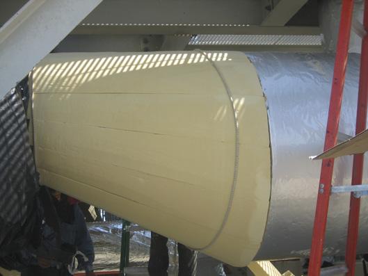
Figure 1. Trymer PIR is easily fabricated for a correct fit.

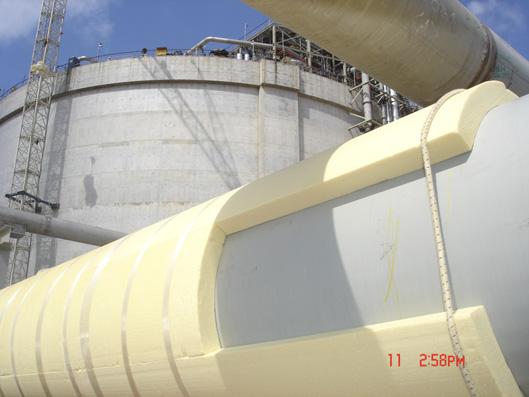
Figure 2. Trymer PIR offers lower total thickness.
Ease of fabrication
One of the crucial characteristics to ensuring an insulation system works successfully is fabricating it correctly to fit the pipe, fittings, and other pipe system components. One of the primary benefits of using a PIR insulation like TRYMER is that it is easy to fabricate correctly both in the fabrication shop and in the field. In fact, it is so easy to fabricate, that in addition to being used for insulating purposes, TRYMER is often used on movie sets, where it is carved into various components for set backgrounds. In LNG applications, this fabricability can be a key differentiator that supports a tight fitting and successfully installed insulation system. In comparison, other insulation materials used in LNG applications are commonly known to be dusty, more difficult, and costlier to fabricate and install.
Compressive strength
Compressive strength comes into play when considering the importance of ensuring the insulation system operates as designed. The great degree of caution needed to minimise heat gain into the LNG system means that it is crucial that the insulation maintains its thermal performance. This means that it must remain at its designed and specified thickness and shape so that it can maintain its thermal performance and help protect the vapour retarder from damage. As a result, many insulation system designers prefer to specify insulations with a higher compressive strength, like TRYMER PIR or cellular glass, to ensure that the insulation is strong enough to withstand the typical abuse it will experience throughout its lifetime.
Water resistance
system designers should consider when selecting an LNG insulation material are outlined.
Thermal conductivity
Since limiting heat gain into the LNG system is one of the crucial requirements in an LNG facility, the thermal performance/conductivity of the insulation is one of the most important features designers should consider when selecting an insulation material. The thermal conductivity of the insulation will determine how thick the insulation needs to be to effectively limit heat gain to the system. The insulation material type and the insulation’s standard thicknesses will determine how many layers of insulation are needed to achieve the necessary thermal performance. For example, JM’s polyisocyanurate insulation, TRYMER®, comes in thicknesses up to 3 in. and falls in the middle in terms of thermal performance when compared with other cryogenic insulations. By using TRYMER, the necessary thermal performance can be achieved in fewer layers than the least thermally conductive materials that come in thicknesses of 10 mm maximum. At the same time, it still offers a lower total thickness than the more thermally conductive cryogenic insulation materials. This creates a unique situation where TRYMER PIR is often the most economical choice both in terms of material costs (including insulation, vapour retarder, and jacketing) and installation costs.
Given that the operating temperatures in LNG facilities are so incredibly low, ensuring water and water vapour do not infiltrate the system is critical. Liquid water is highly thermally conductive while frozen water expands, increasing the potential for damage to the tightly fitting insulation, jacketing, and vapour retarder, ultimately leading to large increases in heat gain into the LNG. For this reason, all insulations used in cryogenic applications require a properly installed vapour retarder (often more than one), even if the insulation is closed cell, such as TRYMER PIR or cellular glass.
The addition of vapour stops
Vapour stops (also known as vapour dams) are the part of an insulation system constructed from vapour retarding joint sealant or mastic, usually reinforced with a coarse fibre mesh. They adhere to the pipe, go up the face of the insulation at a circumferential joint, and then attach to the primary vapour retarder on the outside surface of the insulation.
The purpose of a vapour stop is to greatly reduce the movement of water and water vapour axially (in a direction lengthwise down the pipe) through the insulation system.
Entry of water and water vapour into a cold insulation system, especially a cryogenic insulation system, is a primary source of problems with the insulation system. It can greatly reduce the performance of the insulation, lead to excess condensation on the insulation system outer surface, contribute to corrosion of the underlying pipe or vessel, and, in particularly bad situations, lead to ice formation in and on the insulation system. Such ice formation can physically damage the insulation system, the pipe, or nearby gauges and equipment.
Vapour stops are used at these types of locations for three specific reasons.
At the point where the insulation system terminates
This point could be on a dead leg of pipe, on a vessel or equipment support leg that is insulated for some distance away from the primary vessel insulation, or on some sort of internal pipe support such as those used on vertical pipes where the support is insulated for some distance away from the primary pipe insulation. In all these cases, the insulation ends. This end point is a location where water and water vapour could readily enter the insulation system and travel through the insulation via various paths. A vapour stop is installed at this location to prevent, or at least greatly reduce, the movement of water through it and hence into the insulation system.
On either side of insulation system locations that are known problem areas for water intrusion
One example of these problem areas is a valve. The valve stem or some part of the valve almost always protrudes through the insulation system, thus penetrating the vapour retarder. Installers take great care to seal the insulation system at this penetration location using sealants and caulks, but this seal is never as good as the vapour retarder on the rest of the insulation system and is subject to degradation from sunlight. If the seal is around an actual valve stem, when this stem is turned or moved, it will break the seal. Another example of a known problem area for water intrusion is a portion of the pipe system that requires repeated maintenance and so is covered with removable insulation to facilitate that maintenance. The vapour retarder on a removable insulation system is seldom very good, so it will more readily allow water and water vapour movement through the removable insulation and into the insulation system.
In both of these examples, a vapour stop should be installed on either side of the problem area. Another way of viewing this sort of vapour stop is that it is a subset of the item raised in the first point. The main insulation system terminates on either side of the problem area, and a vapour stop is installed. Regardless, the purpose of vapour stops is to prevent water that enters the insulation system at the problem location from moving into the rest of the insulation system. The vapour stop isolates and limits the potential for damage caused by the water entering at such problem locations.
Periodically on a run of pipe as a protective measure
Even in the absence of a known problem location, there is the possibility that the insulation system could be damaged or installed improperly. Either of these scenarios could allow water or water vapour to enter the system. Vapour stops are located periodically along a run of pipe to limit the extent of the water movement in such a case. The purpose of this vapour stop location is to isolate the damage from water entry to a smaller portion of the insulation system. If the system can be shut down and the pipe allowed to warm, this reduces the amount of the insulation system that must be repaired. If repairs are not possible due to the undesirability of turning off the system and allowing it to warm, then periodic vapour stops can limit the increase in condensation and heat gain to only a small portion of the total pipe length. Bear in mind that in this case, there is no single correct spacing distance for vapour stops on a run of pipe. This spacing depends on many factors including quality/cost of the original insulation system design, quality/cost of the installation, and frequency of inspection and maintenance. Typical spacing for vapour stops on a run of pipe would range from every 20 ft to every 100 ft.
Summary
It is important to consider each of these characteristics as an LNG insulation system is being designed to help ensure that the system has a long service life. There are numerous examples of LNG facilities around the world with properly installed PIR insulation that have been functioning successfully for more than 20 years.
ACUUM JACKETED P VACUUMJACKETEDPIPE

THE MOST COST-EFFECTIVE WAY TO TRANSFER CRYOGENIC LIQUIDSTHE MOST COST-EFFECTIVE WAY TO TRANSFER CRYOGENIC LIQUIDSTHEMOSTCOST-EFFECTIVEWAYTOTRANSFERCRYOGENICLIQUIDS LNGLNG applicationsapplications
VJP reduceS boil-off gas (BOG) resulting in higherVJPreduceSboil-offgas(BOG)resultinginhigher LNGLNG flow over greater distances.flowovergreaterdistances. less liquid losses and/or reduced reliquefaction.lessliquidlossesand/orreducedreliquefaction. resulting in lower overallresultinginloweroverall operation costs.operationcosts.

Unlocking North America’s Energy Potential


