11 minute read
Cracking a cold case


J. Randolph Kissell, Trinity Consultants, USA, solves a cold case, and outlines how to size wind girders for tanks of any diameter.
Cylindrical aboveground storage tanks are very effi cient at resisting hydrostatic pressure caused by the liquid they store, which puts the cylindrical shell in tension. Conversely, cylinders are less effective in resisting external pressure from wind, which places the shell in compression that can cause buckling. Tank design standards such as API 650 have long required that shell buckling strength be compared to these compressive stresses, and that stiffening rings (called wind girders) be provided when the shell would buckle without such stiffeners.
Storage tanks without fi xed roofs, called open top tanks, always require a wind girder near the top of the shell to resist buckling from the wind. Tanks with fi xed roofs and open top tanks sometimes require a stiffening ring between the tank bottom and the tank top; such rings are called intermediate wind girders. The maximum distance between stiffened points (the tank bottom, a wind girder, or a fi xed roof) was established by buckling theory for cylinders developed in the 1930s. McGrath adjusted the theory to address cylinders with varying thickness over their height and incorporated this into API 650 in the 1960s. The resulting 650 equation relating shell thickness (t), unstiffened shell height (H), tank diameter (D), and horizontal wind pressure (PWS) is well documented:
Conversely, the origin of API 650’s wind girder size requirement is murky, based on an unpublished 1929 paper by Boardman, who proposed that the bending moment in the wind girder caused by wind on the tank shell is:
M = 0.01PWSHD2 (2)
He noted that: “This formula has not been derived […] but at least its form has been shown to be logical”. Nonetheless, as far as estimates go, it was a fortunate one because it worked for tanks of that day. But as tank diameters
Pws = 2.1 E (H/D)(D/t)2.5 (1)
increased, the estimate seemed to become extremely conservative. In 2016, API 650 was revised to limit the diameter term in this requirement to 200 ft, regardless of the actual tank diameter, codifying an informal practice used since the 1970s.
Many have tried to explain this, only to be reduced to hand waving. What seems especially counter intuitive is that API 650 states that the top wind girder’s section modulus is strongly dependent on tank diameter, increasing with the diameter squared for tanks up to 200 ft dia., but not for tanks over 200 ft dia.. For example, if API 650’s rule for tanks under 200 ft was applied for a 300 ft dia. tank, the wind girder section modulus should be (300/200)2 = 2.25 times the size 650 requires. This is way beyond what safety factors cover.
Furthermore, the section modulus for intermediate wind girders has no such limit; it is required to increase with tank diameter for all diameters. Yet API 650’s apparently irrational wind girder requirements have worked. Tanks rarely collapse under wind pressure, even during hurricanes and tornadoes. Of course, this might mean that the requirements are very conservative, or that experience with tanks over 200 ft dia. is too limited to draw conclusions regarding the validity of
API 650’s rule. As demand grows for tanks with greater capacities, however, understanding how wind girders should be sized becomes more urgent. A rational explanation for this paradox is, however, fi nally available.
Table 1. Maximum external shell wind pressure coefficients, H/D = 0.5 (+ is inward)
Tank top External pressure coefficient Cp
Windward 90˚ to wind Leeward Average radial Net horizontal
Open 1.75 -0.2 0.4 0.51 0.56 Closed 1.0 -1.0 -0.4 -0.26 0.55
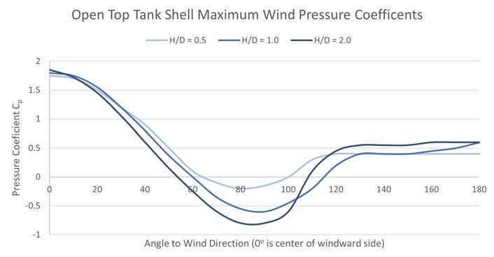

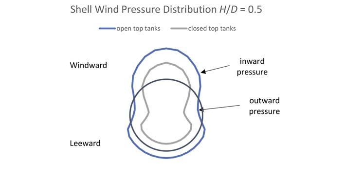
Figure 1. Plan view of tank shell wind pressure for open and closed top tanks.
Figure 2. Open top shell wind pressure.
Figure 3. Wind pressure vs height on an open top tank shell.
Wind girder loading
In his 1988 wind tunnel study, MacDonald measured the wind pressure distribution for tanks with a height to diameter ratio (H/D) of 0.5, typical of a 100 ft dia. tank, as shown in Figure 1 and summarised in Table 1. Positive pressure acts inward on the shell; negative pressure acts outward.
MacDonald also showed that the wind pressure distribution around the tank circumference depends on the tank’s H/D ratio. As this ratio decreases (as tank diameter increases, H/D decreases because tank height is typically about 50 ft for all tank diameters), the ovalising effect of the wind on the shell decreases slightly. This is because the outward suction of the wind at roughly 90˚ to the wind direction decreases in magnitude and extent as illustrated in Figure 2.
H/D ratios of typical open top tanks vary from approximately 1 (a 50 ft dia. x 48 ft tall tank) to 0.2 (a 300 ft dia. x 48 ft tall tank). A 200 ft dia. x 48 ft tall tank has H/D = 0.24, which is less than the smallest H/D ratio investigated by MacDonald. Although MacDonald did not investigate tanks with H/D ratios less than 0.5, his data suggest that as the H/D ratio decreases, the extent and magnitude of the suction portion of the shell perpendicular to the wind decrease. Regardless of the H/D ratio, however, the windward and leeward wind pressure coeffi cients are approximately the same: about 1.8 and 0.4 (both inward) respectively.
MacDonald’s study showed that wind pressure also varies over the tank height, as shown in Figure 3. The average wind pressure on the top half of the shell is approximately 93% of the maximum wind pressure.
Because wind causes pressure, it acts perpendicular to the tank shell. Therefore, wind girders are ring beams with transverse distributed loads. These distributed loads can cause moments, shears, and axial forces in the girders, but the moments cause the signifi cant stresses.

EHS & Engineering EHS & Engineering Support for Tanks Support for Tanks & Terminals & Terminals
EHS Support Emissions Estimating MI and Inspections
Trinity provides terminal operators with a wide range of services to help ensure compliance with applicable environmental rules and regulations.
Permitting and compliance assistance Environmental Justice assessments and assistance NSPS and NESHAP/MACT support Transportation fuel compliance Air dispersion modeling programs and support BREEZE TankESP of fers powerful productivity enhancements to ef fectively manage tank emission calculations.
Select either old or new
AP-42 equations Adjust for mid-month changes in service Calculate emissions from floating roof landing and tank cleaning events Account for changes in tank construction Trinity/Provenance support all aspects of implementing and executing a Fixed Equipment Mechanical Integrity (MI) and Inspection program.
Risk analysis and recommendation support Engineering design Construction management API-certified inspections including NDE, NDT, and UT Full FEMI program support
Moments, shears, and axial forces in a circular ring can be determined by combining cases that have been solved using Castigliano’s second theorem. Many such cases are tabulated in Roark’s ‘Table 17’. This approach can be used to approximately derive Boardman’s guess, which is API 650’s current provision, by combining Roark case 8 for a uniform lateral pressure and case 20 for tangential shear.
The resulting maximum moment in the wind girder due to a uniform horizontal distributed load w over the tank diameter D is:
M = 0.14wR2 = 0.035wD2 (3)
Figure 4 shows the moment in the ring using this method for a 100 ft dia. x 48 ft tall tank with 11 psf wind pressure.
The moment thus calculated varies in sign around the circumference, as shown in Figure 4, causing compression at the outside of the wind girder at some points on the circumference (approximately the portion 40˚ to either side of the wind direction on the windward side and 40˚ to either side of the wind direction on the leeward side) and tension at the outside of the wind girder in the areas perpendicular to the wind direction.
The upper portion of the shell is stiffened against buckling by the top wind girder and the lower portion of the shell is stiffened by the tank bottom. To determine the portion of the shell over which the wind girder resists the wind pressure and thus the distributed load w that acts on the wind girder, the shell can be divided into upper and lower portions by considering its buckling strength. Tanks are typically constructed of 8 ft tall constant thickness courses of decreasing thickness toward the top of the shell. Because the equation for shell buckling strength is based on a shell with the same thickness from bottom to top, the shell height H in the shell buckling strength equation must be adjusted to account for this.
API 650 calls the adjusted shell height the transformed shell height Htr. Because API 650 uses the smallest shell course thickness in the shell buckling strength equation, the height of each shell course thicker than the least shell thickness is adjusted downward to determine the transformed shell height. API 650’s transformed shell height is the height of a shell with the least thickness used in the shell that has the same buckling strength as the actual shell:
As shown in Figure 5, the wind girder supports the top half of the transformed shell height and the tank bottom supports the bottom half of the transformed shell height against buckling.
The transformed shell height is always less than the actual shell height because the transformed height of shell courses thicker than the least shell thickness is less than their actual height. For example, for a 200 ft dia. x 48 ft tall tank designed for a product specifi c gravity of 0.8, the transformed shell height is 18.22 ft.
API 650’s current provisions assume that the top ¼ of the actual shell height H equals ½ the transformed shell height, in which case w = PWSH/4. This can be demonstrated by substituting PWSH/4 for w in equation (3), giving a wind girder moment:
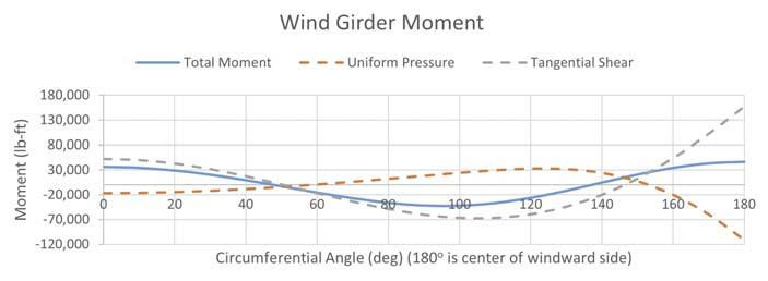
Figure 4. Moment in a circular ring under uniform projected wind pressure.
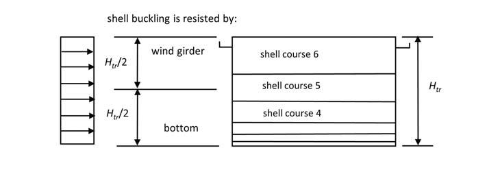
Figure 5. Transformed shell height.
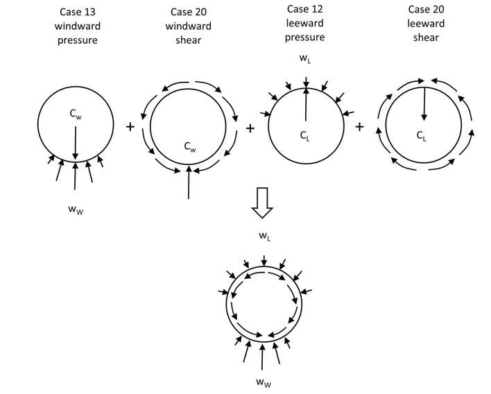
Figure 6. Wind girder moment from varying wind pressure around the tank circumference.
M = 0.14wR2 = 0.14(PWS H/4)(D/2)2 = 0.00877PWSHD2 ≈ 0.01PWSHD2 (5)
API 650 uses this moment to determine the required section modulus S by limiting the bending stress it causes (M/S) to the wind girder’s yield strength. This wind girder moment estimate is approximate because it only models the net horizontal wind pressure without accounting for pressure variation around the tank circumference and assumes that half of the transformed shell equals a quarter of the actual shell height for all tanks. For a 200 ft dia. tank, half of the transformed shell height is (18.22 ft)/2 = 9.11 ft, only 19% of the actual shell height.
The pressure distribution given in Figure 1 gives a different maximum wind girder moment than the average
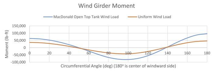
Figure 7. Wind girder moment from uniform and varying pressure distributions. M = 0.14(96.1/46.3) wR2 = 0.28wR2 = M = 0.28PWS(Htr/2)(D/2)2 = 0.035PWSHtrD2 (6)
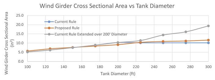
Figure 8. Wind girder size by current and proposed rules.
The approximation that the wind girder supports the top ¼ of the shell height is reasonably accurate for tanks under 200 ft dia., but overly conservative for tank diameters over 200 ft. For large tanks, lower shell courses are much thicker than the minimum shell thickness, and the transformed shell height is short. By eliminating this approximation, the empirical rule that wind girders for tanks over 200 ft dia. need not be larger than wind girders for a 200 ft dia. tank can be eliminated without requiring signifi cantly larger wind girders. Figure 8 compares wind girders using the current and proposed rules.
horizontal pressure. To determine the moment from the actual pressure distribution, four Roark cases were combined, as shown in Figure 6.
The resulting moments are shown in Figure 7 and compared to the moment distribution from the uniform projected pressure shown in Figure 4.
Unsurprisingly, Figure 7 shows that moment in the wind girder depends on the wind pressure distribution. The more precise wind distribution has a greater maximum moment (96.1 ft-k) than the projected uniform distribution (46.3 ft-k). Comparing the maximum moment for both distributions, which occurs at the centre of the windward side, shows that the maximum moment in the wind girder is:
Conclusion
API 650’s current requirement for wind girder size is empirical and becomes inaccurate for tanks over 200 ft dia. By revising it as outlined in this article, the requirement is made rational and accurate. This cold case has fi nally been solved.


Your Specialist for PRESSURE RELIEF SOLUTIONS
Consulting. Engineering. Products. Service. T +49 2961 7405-0 info@rembe.de