10 minute read
Protecting marine structures


Many storage terminals and petrochemical facilities are located near a navigable waterway and have shore marine structures nearby to allow for tanker traffi c to receive or send product. These could include docks, jetties, piers, seawalls, mooring, and turning/mooring dolphins and other similar structures. These metallic structures are subject to corrosion and are generally protected by cathodic protection systems. This article provides a general overview of cathodic protection for these structures and discusses some of the common strategies that are frequently employed to protect them.


Two basic types of cathodic protection


There are two basic types of cathodic protection and both are used to protect near shore marine structures. It is not uncommon to employ both strategies to protect different structures in the same facility. Each of these systems have their advantages and disadvantages, and it is important that the design engineer consider the application specifi cs to choose the appropriate system(s) for the application.
The fi rst type of system is a galvanic anode system (also commonly referred to as a sacrifi cial anode system). Galvanic anodes are cast hunks of a specifi c metal alloy that are typically attached directly to the structure. For seawater applications, these are commonly aluminium or zinc anodes, while brackish or freshwater applications might utilise zinc or magnesium anodes. These metals are inherently more electro-negative than steel so that when they are coupled to a steel structure, current will fl ow from the more electro-negative anode to the metallic structure. When properly applied, this electrical current, generated from the anode, fl owing through the electrolyte (water) to the structure (or cathode), reduces the corrosion rate to virtually nothing – this is, by defi nition, cathodic protection.
The other type of system is an impressed current system. Impressed current systems work in the same basic manner as galvanic systems; however, for these systems, an external power supply is used to drive current off the anode, through the electrolyte, to the structure being protected. The use of an external power supply allows the cathodic protection system to utilise anodes that are not required to be more electro-negative than the structure being protected. These anodes can be chosen for other properties, namely their ability to discharge current much more cost-effectively than massive hunks of metal alloy. They can do this because of the use of an external power supply that will drive the fl ow of current.

The key differences between an impressed current anode system and a galvanic anode system for near shore marine structures are discussed here:
Anode consumption rates
Aluminium alloy anodes, such as those typically used in seawater applications, have a nominal capacity of 2000 amp-hr/kg, while titanium anodes with a mixed metal oxide coating (MMO), commonly used in near shore applications, have a capacity of approximately 1000 times the equivalent capacity of aluminium anodes. This means that far fewer anodes are required and the expected life of the system can be much longer.
Current density limits
Aluminium alloy anodes can operate at a maximum current density (current being discharged for a given surface area) of 15 amps/m2 but are typically designed to operate at much lower current densities. Impressed current MMO type anodes can operate at current densities up to 500 amps/m2; however, in most cases the operating levels are much lower. The higher current density limit means that the designer can use fewer impressed current anodes at a much higher output.

Ted Huck, MATCOR Inc., USA, explores cathodic protection options for terminal marine structures including docks, jetties, piers, seawalls and pilings.


Driving voltage

Aluminium alloy anodes have a natural potential difference of approximately 0.5 V between the anode and the steel structure being protected. This is the limit of the driving force available to the cathodic protection (CP) designer when using galvanic anodes. Impressed current anodes utilise an external power supply typically operating at 10 – 30 V of driving force, which allows fewer anode systems to protect larger structures with high current requirements.
No power supply
While aluminium alloy anodes are not as effi cient or as powerful as impressed current anodes, in many applications the ability to operate without the use of an external power supply is a huge advantage. The need for electrical power and extensive electrical cabling is greatly diminished or eliminated with galvanic systems.
Ultimately, the system designer needs to be familiar with both options and make an economic evaluation of the appropriate approach taking into consideration anode system life, material and installation costs, operating factors and constraints, and other factors to determine which type of system is best for a given application.
Land side design considerations
While this article is focused on near shore marine structures, it is important to note that these structures almost always consist of a mix of wetted surfaces and buried surfaces. Consider a sheet pile wall being installed as part of a new berthing facility. One part of the structure is exposed to the water, while the other side of the same structure is exposed to soil. Both sides of the sheet wall are subject to corrosion and must be considered by the corrosion engineer. Typically, soil has a much higher resistance than seawater, brackish water, or even fresh water. Because of the higher soil resistance, land side protection is more often accomplished using impressed current systems because of the large amounts of current required to protect them.
Another important consideration for land side cathodic protection has to do with other nearby structures, including grounding systems, buried pipelines, storage tanks both above and below ground type, and/or building foundations. These ‘foreign’ structures can all have an impact on the performance of the cathodic protection system and must be considered during the design and installation.
Water side considerations
When designing anode systems to protect the wetted surfaces of these structures, there are some important considerations that must be given during the design. The fi rst consideration is installation: can the anodes be installed prior to the structure being installed? Water side installations can get very expensive if specialised industrial marine divers and diving support equipment and personnel are required. In some cases, the anodes can be cost-effectively installed on the structure prior to the structure being erected. In other cases, the installation of brackets and other devices can be designed and installed in advance, thereby minimising the installation efforts required for a successful anode installation.
Another important consideration for water side installations is the anode location. For galvanic anodes, the anodes are often located in very close proximity to the structure, but for impressed current anodes, the anodes are generally located some distance away from the structure to allow the higher capacity anodes to cover a larger area of the structure. This might mean putting an anode on the sea fl oor well away from the structure. For these sea fl oor type anodes, issues such as dredging become critical. Installing a remote anode in a location where dredging may occur would likely
be a concern. In some cases, steep concrete sloped channels might preclude the use of anodes positioned on the sea fl oor as they may not remain in place.
Another concern that applies to extreme cold-water applications is freezing. In these applications, ice fl oes can cause severe damage to anodes and cabling systems alike.
New construction vs retrofit application
Another factor that the designer must consider is whether this is a new installation or a retrofi t application. For new installations, site access issues may be quite different than for an existing structure requiring a cathodic protection system replacement. For new installations, the option to have anodes or anode fi xtures installed on structures prior to their installation can have a tremendous impact on the overall installation costs – something that may not be an option when addressing an existing structure.
Case study
Along the Houston Ship Channel, Texas, US, there is a large concentration of terminals and petrochemical facilities, and almost all of them have some form of marine loading/unloading facility. On a recently completed project, a terminal facility had an old sheet pile wall that was approaching the end of its useful life and was scheduled for a replacement system to be installed in the same location. The project consisted of installing cathodic protection for a new 275 ft-long combi-wall that was being installed directly in front of an existing sheet pile wall. The new combi-wall utilised 60 in. dia. steel pipe pilings connected with conventional Z pilings driven to a depth of 100 ft. In addition to the new wall, new dolphins were being installed in the channel for mooring and turning purposes.
The system designer had multiple structures to consider and elected to use a range of cathodic protection solutions. For the isolated dolphins located in the channel, conventional galvanic anodes were installed with the dolphins. These small, isolated structures were ideal for direct connected zinc galvanic anodes and eliminated any requirements for extensive cabling in the channel. Given the brackish nature of the Houston Ship Channel, zinc anodes were the preferred anode system for this application.
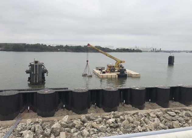
The water side of the new combi-wall was designed to be protected using two sled-type anodes located in the channel with cabling routed back to shore. Sled anodes are typically used to protect large surface areas utilising relatively high output anodes – commonly titanium coated MMO type anodes, given their long life and high effi ciency. The sled anodes are built with concrete ends to secure the sled in place on the channel fl oor. The sleds manufactured for this application were a little over 5000 lbs each. One of the advantages of a sled anode is the ease of installation. The anodes are lowered in place using a crane, and the cabling is routed back to shore with weights to hold the cabling in place. The entire installation takes only a few hours per anode assembly.
The space between the existing sheet pile wall and the new combi-wall was fi lled with soil, and individual titanium-coated MMO tubular anodes were installed every 10 ft to protect both the interior surface of the new wall and the exterior surface of the existing wall. MMO tubular anodes are available in a range of sizes, and for this application the tubes selected were standard 1 in. dia. x 1 m long tubes. In addition to installing the tube anodes, soil access tubes were provided to assure future access for testing.
The interior surface of the existing wall had previously been protected by a deep anode installation, and the project included replacing in kind that system which was nearing the end of its useful life. Deep anode systems are commonly used in facilities where surface real estate is at a premium. A vertical hole, typically 8 – 10 in. dia., is drilled to a depth suffi cient to have the anodes be considered remote from the target structure – usually 200 – 300 ft in depth. Anodes are installed in the bottom of the hole and the hole is fi lled with a conductive carbon backfi ll to improve the anode performance. The top of the hole is fi lled with gravel, sand or bentonite to complete the installation.
For this example, project to protect this new sheet pile wall, a combination of anode types, installation methodologies, and anode confi gurations were employed to provide what the designer hoped would be an optimal installation.
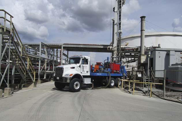
Figure 1. Vertical drill rig used to install deep anode systems in a vertically drilled hole, typically to depths of 50 – 150+ m.
Figure 2. Sled Anode Assembly being installed in the channel using a barge mounted crane to protect the combi-wall in the foreground.