Capella Laboratory Science and Research Centre
HybriDfMA Frames System



The Capella Laboratory was commissioned by Cambridge University to provide a world-class Bioscience and Research & Development facility constructed to accommodate the following important health research groups:
• Cambridge Stem Cell Institute
• Cambridge Institute of Therapeutic Immunology & Infectious Disease
• The Milner Therapeutics Institute
• Cambridge Centre for Haematopoiesis and Haematological Malignancies
Located at the Cambridge Biomedical Campus that includes the renowned Addenbrookes Hospital, the masterplan of the overall site development required an urbanism to the campus rarely seen in healthcare: high quality architecture, public spaces and landscape as set out by architects Allies and Morrison.
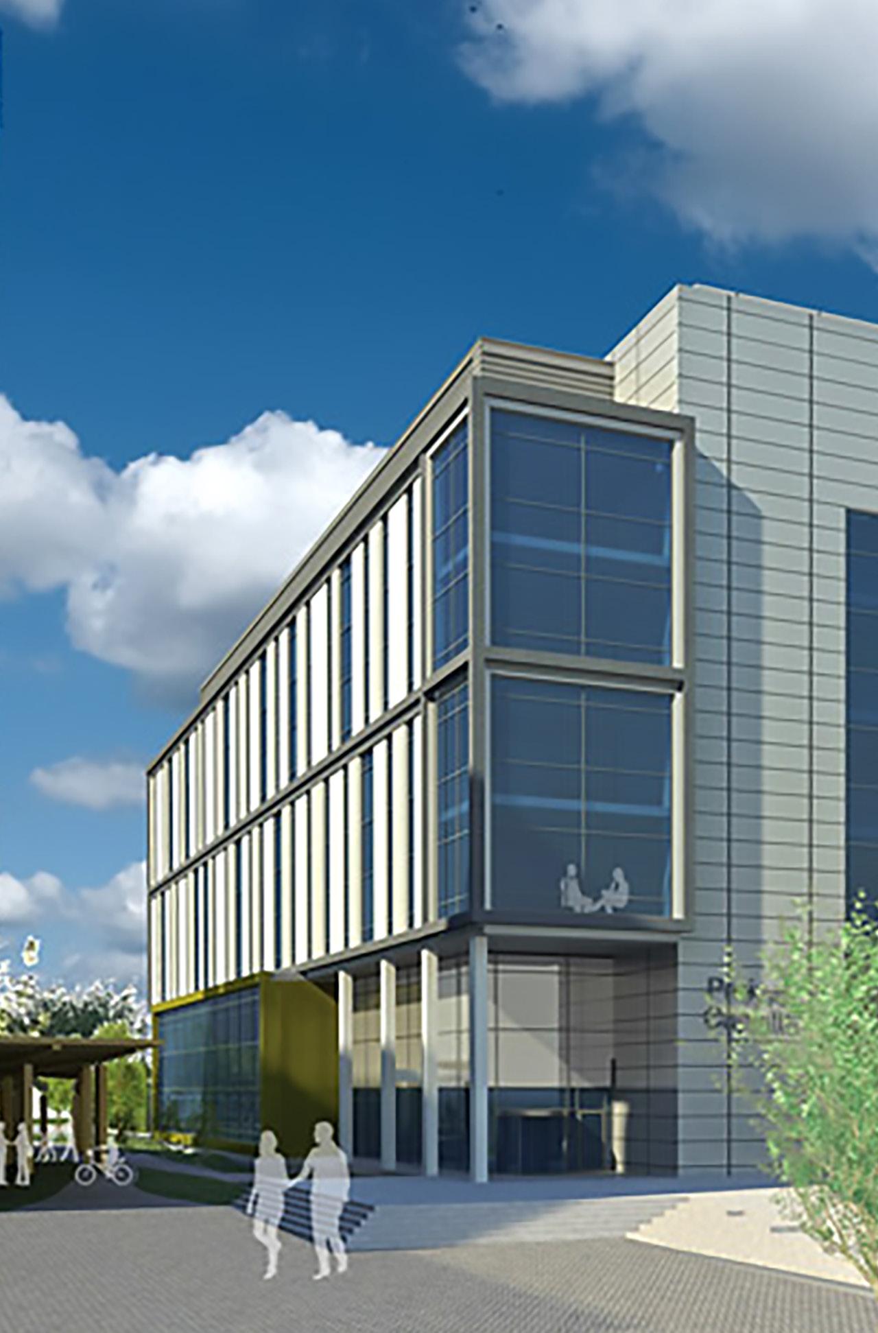
This project exceeds those initial requirements by its striking appearance with architectural design by Fairhurst Design Group and Arup as Consulting Engineer.

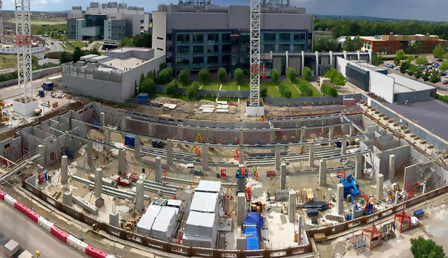
The laboratory is located in proximity to other existing and operational buildings and during the tender period Kier Major Projects quickly realised that the monolithic in situ concrete construction initially envisaged would create problems with excessive deliveries, noise and disruption to the busy hospital environs and campus as well as the potential lack of sufficient local concrete supply.
Keir having worked with PCE Ltd on other large scale offsite construction delivered projects thus requested them to propose an alternative design and build solution using PCE’s HybriDfMA Frames System solution for the structural frame construction, including basement and external architectural envelope.
From approval of the PCE structural design concept and final design commitment to completion of the complex structural package on site took just 17 months to provide the 6-storey structure within excess of 17,000m² gross area. The on site build time included in the above 17months was just 32 weeks giving a reduction of over 20 weeks compared to the initial on site in situ concrete programme option.

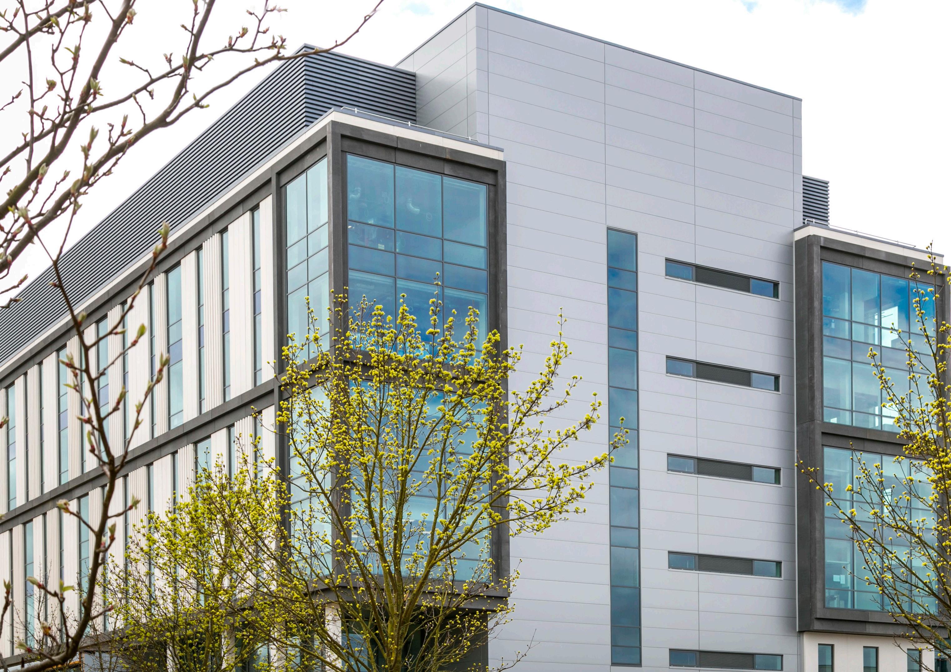
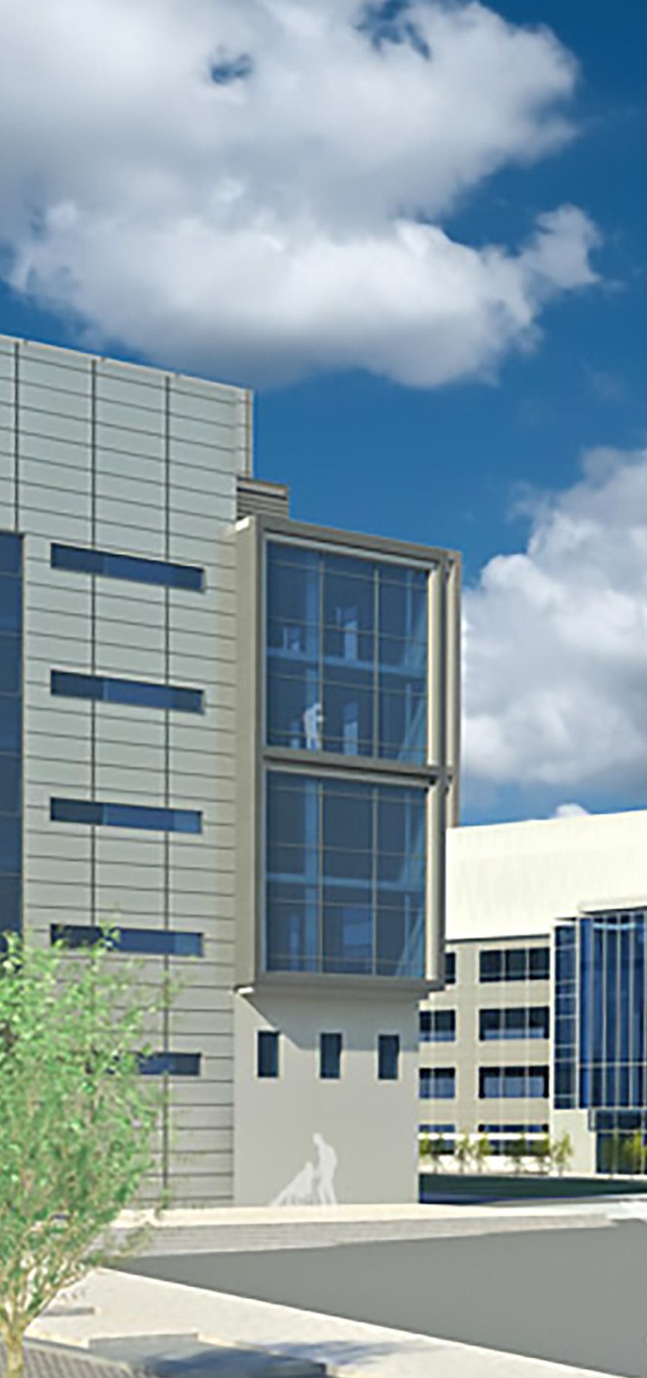
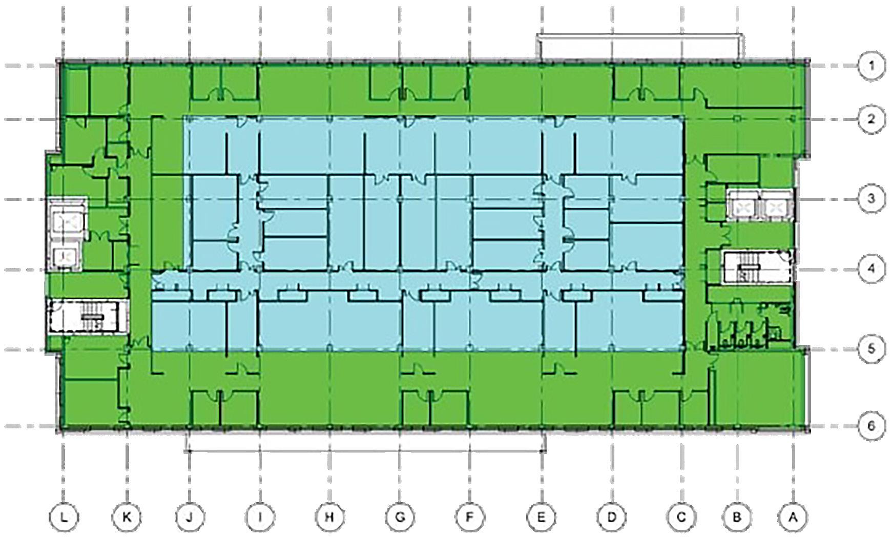
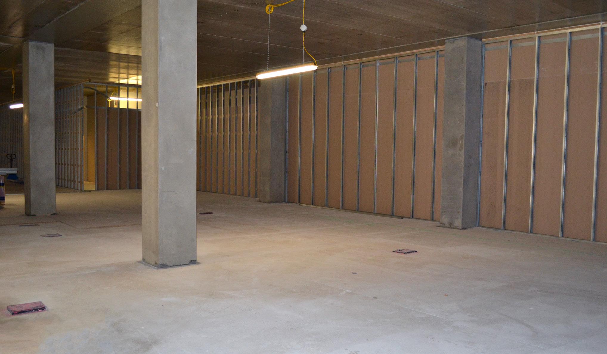
The laboratories are arranged along the centre of the structure with ‘writeup’ spaces adjacent to the edges with the façade, providing natural light. The aspiration was to create clear, flexible spaces with no down-stands to simplify the complex services integration whilst taking benefit of exposed concrete surfaces wherever possible.
With the ethos of all those involved with the project working as one delivery team, the adoption of offsite construction solutions to address the significant logistical and construction management challenges of the site was maximised.
The team optimized structural efficiency, internal finish and the simplification of construction. This, coupled with the integration of reconstructed stone façade with pre-installed glazing, enabled eighty per cent of the structural frame together with the façades being built offsite. This approach provided the ultimate client, University of Cambridge, with clarity concerning certainty of costs, quality and overall project delivery.
PROJECT VALUE
CLIENT
MAIN CONTRACTOR
ARCHITECT
CONSULTING ENGINEERS
PCE LTD PROJECT MANAGER
£79m
University of Cambridge
Kier Major Projects
Fairhurst Design Group Arup
Craig Billyeald


The building was designed to provide world class scientific and research facilities with a stringent requirement to minimize vibrational effects when in use due to the very sensitive scientific equipment installed.
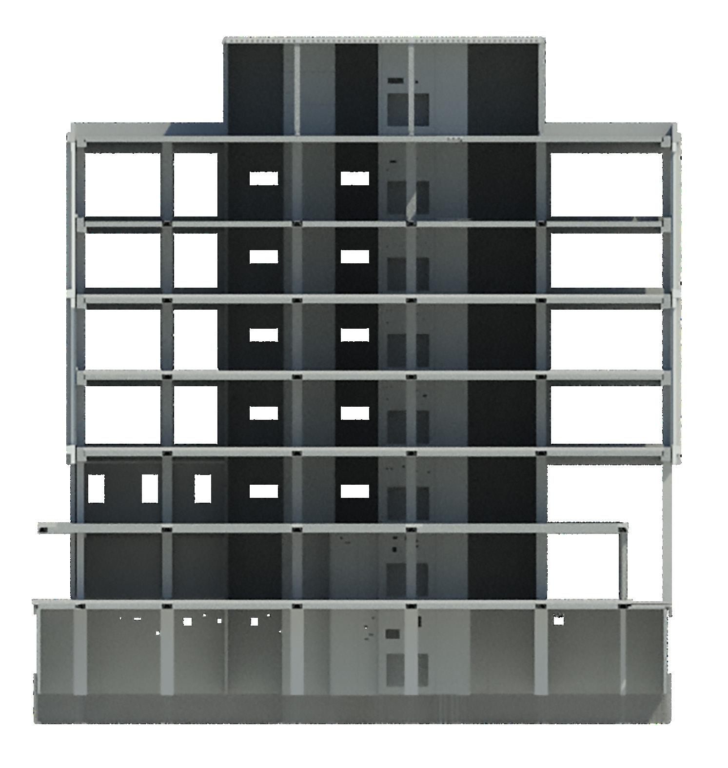
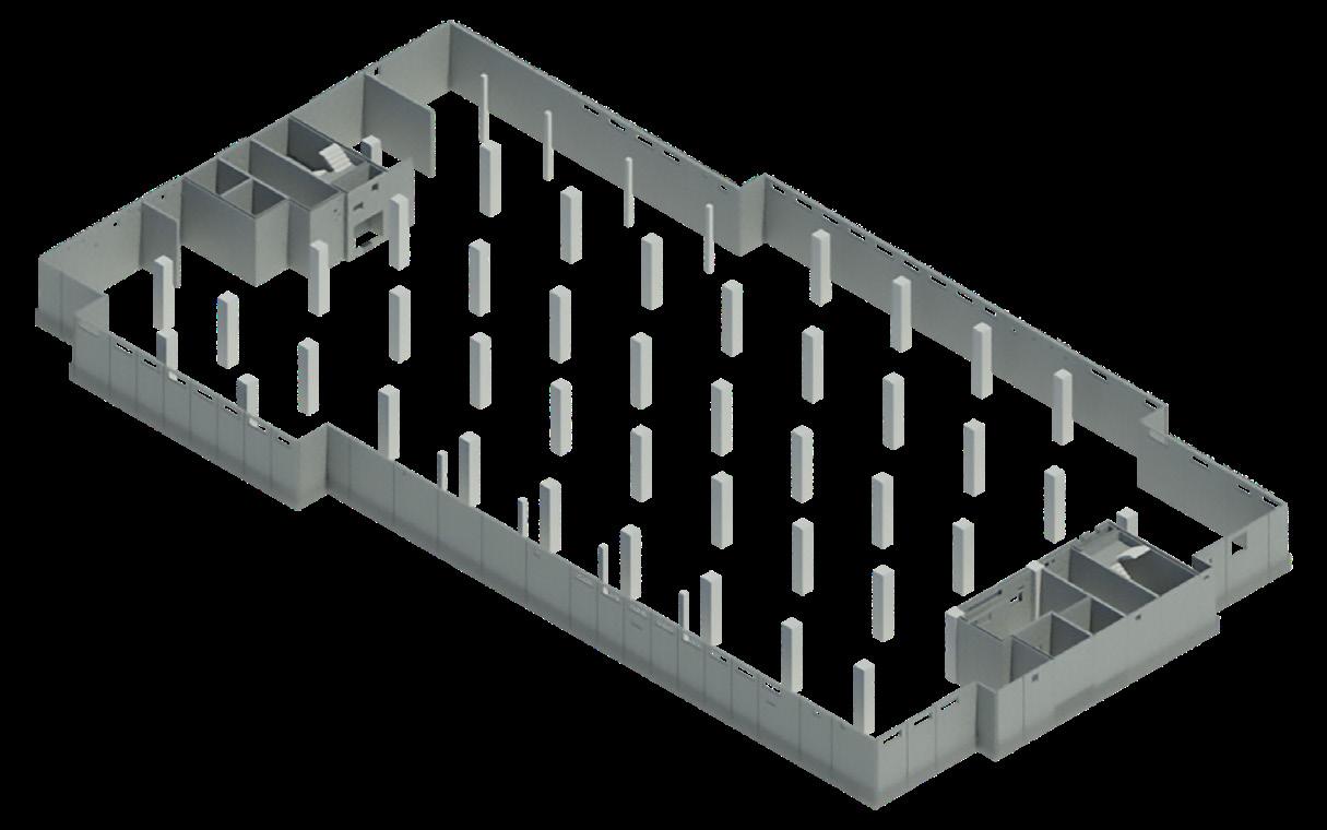
The superstructure which has a 5 metre deep basement and is 7 storeys’ high from ground level, is recti-liner in form with 6.4m grids longitudinally and with transverse non-symmetrical grids ranging between 5.5m and 8.5m.
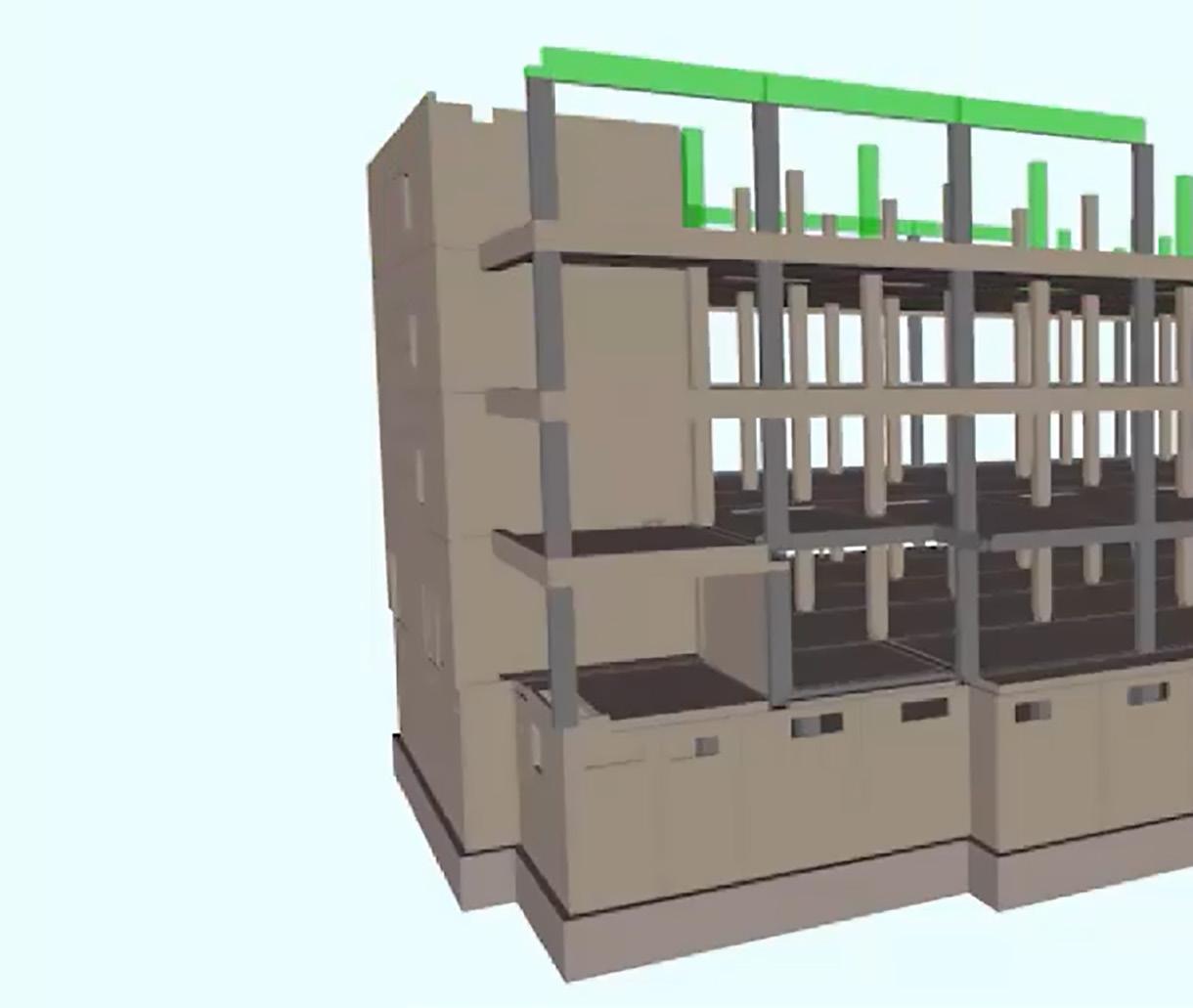
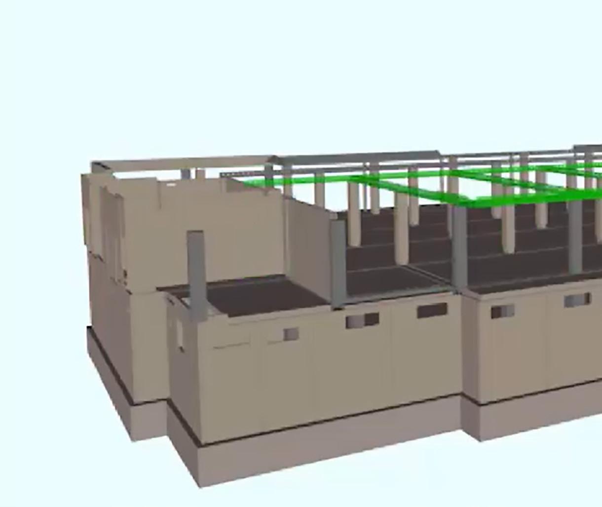
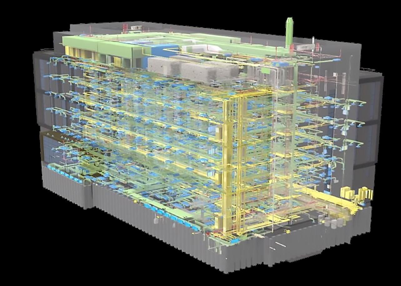
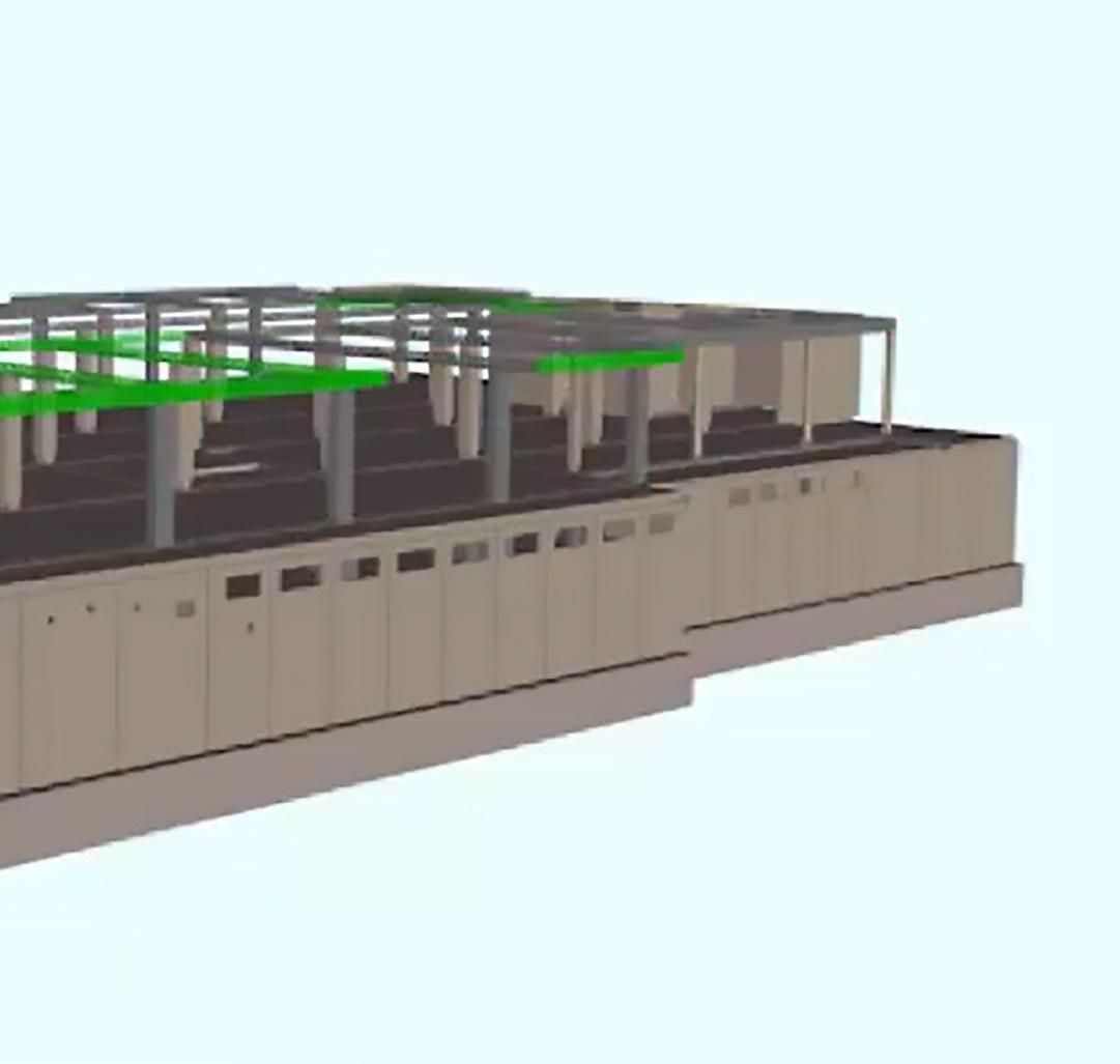
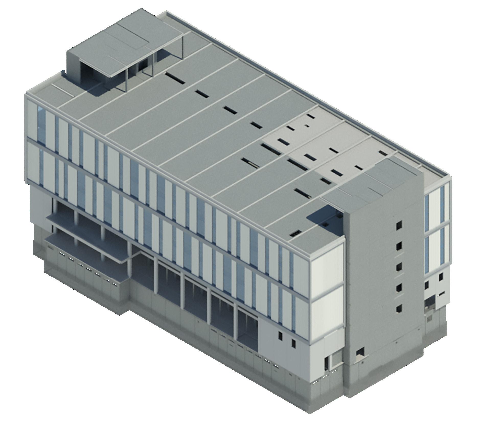
Using the latest Building Information Modelling techniques during the design stage, PCE developed a structural solution for the building that enabled the integration of an extremely complex services strategy, including the pre installation of the main service routes and associated plant, as well as the integration of a precast concrete façade panel solution with glazing installed at the panel manufacturing factory.
The exceptionally low vibration requirement led the design to a deeper suspended floor depth of 600mm than would otherwise be required for just structural purposes.
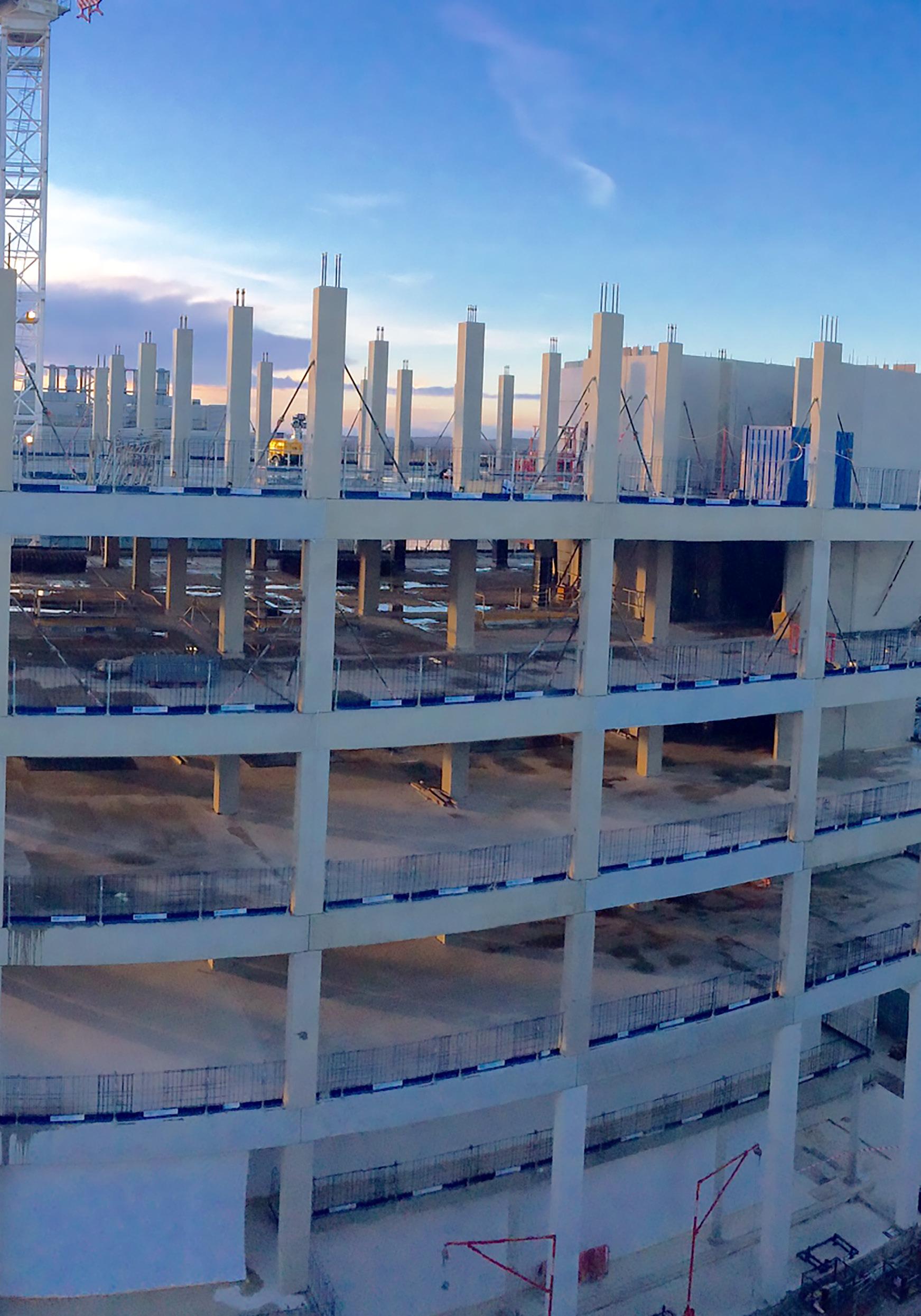
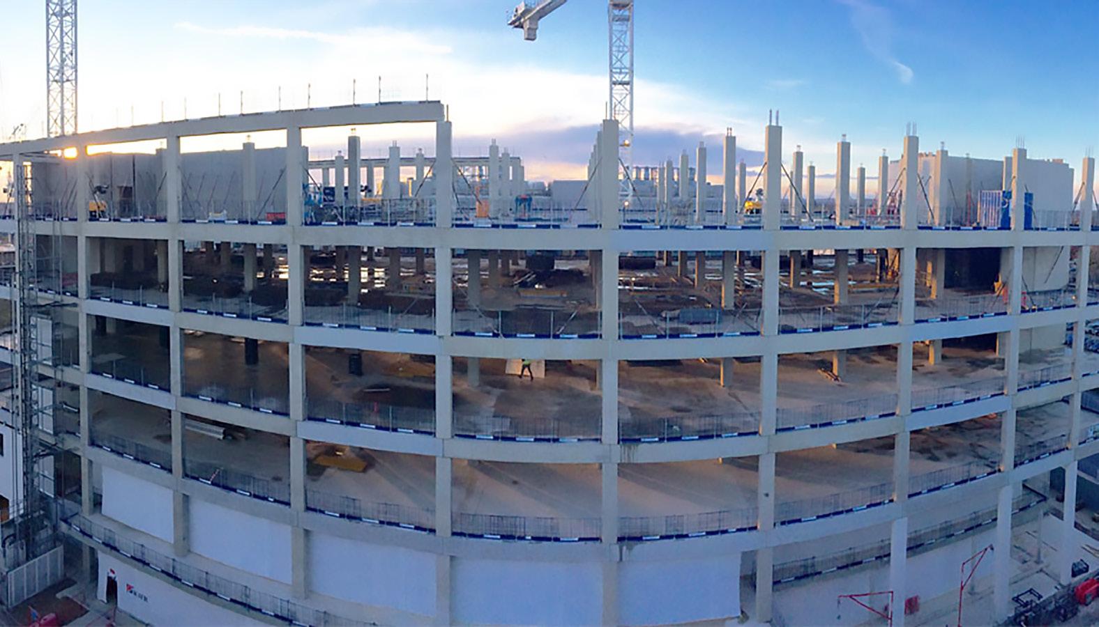
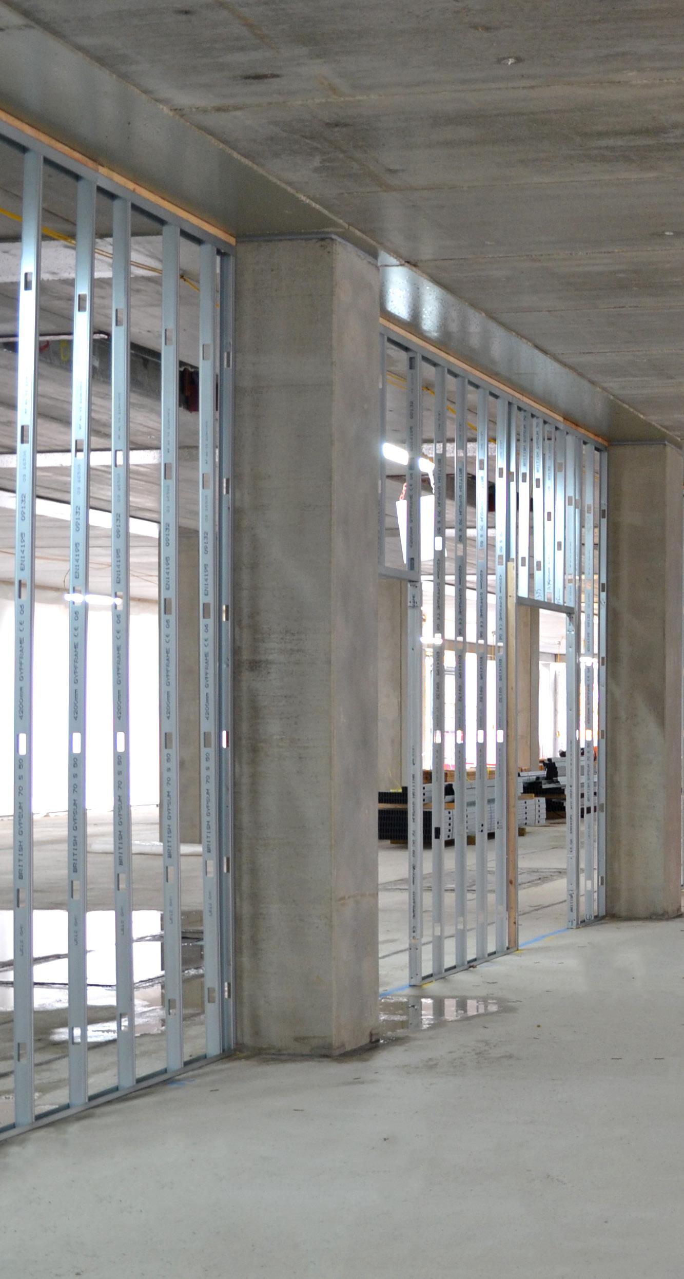
The final structural frame design philosophy adopted was generally precast concrete columns with a combination of precast concrete edge beams and composite structural steel/ reinforced concrete spine beams, supporting the composite floor construction formed from 300mm deep prestressed concrete hollowcore units and a 200mm reinforced in situ structural concrete topping.
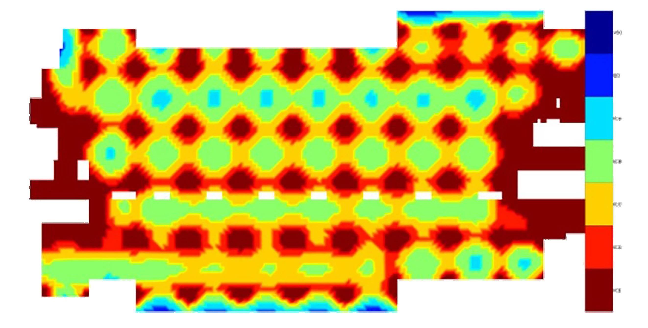
To prove the exceptionally low vibration requirements had been met, a full-scale test of the dynamic properties of one of the floors after construction was carried out using an array of shakers and accelerometers coupled with specialist software. The results showed that the PCE HybriDfMA Frames System solution adopted gave a much stiffer floor plate than predicted using typical conservative design assumptions.
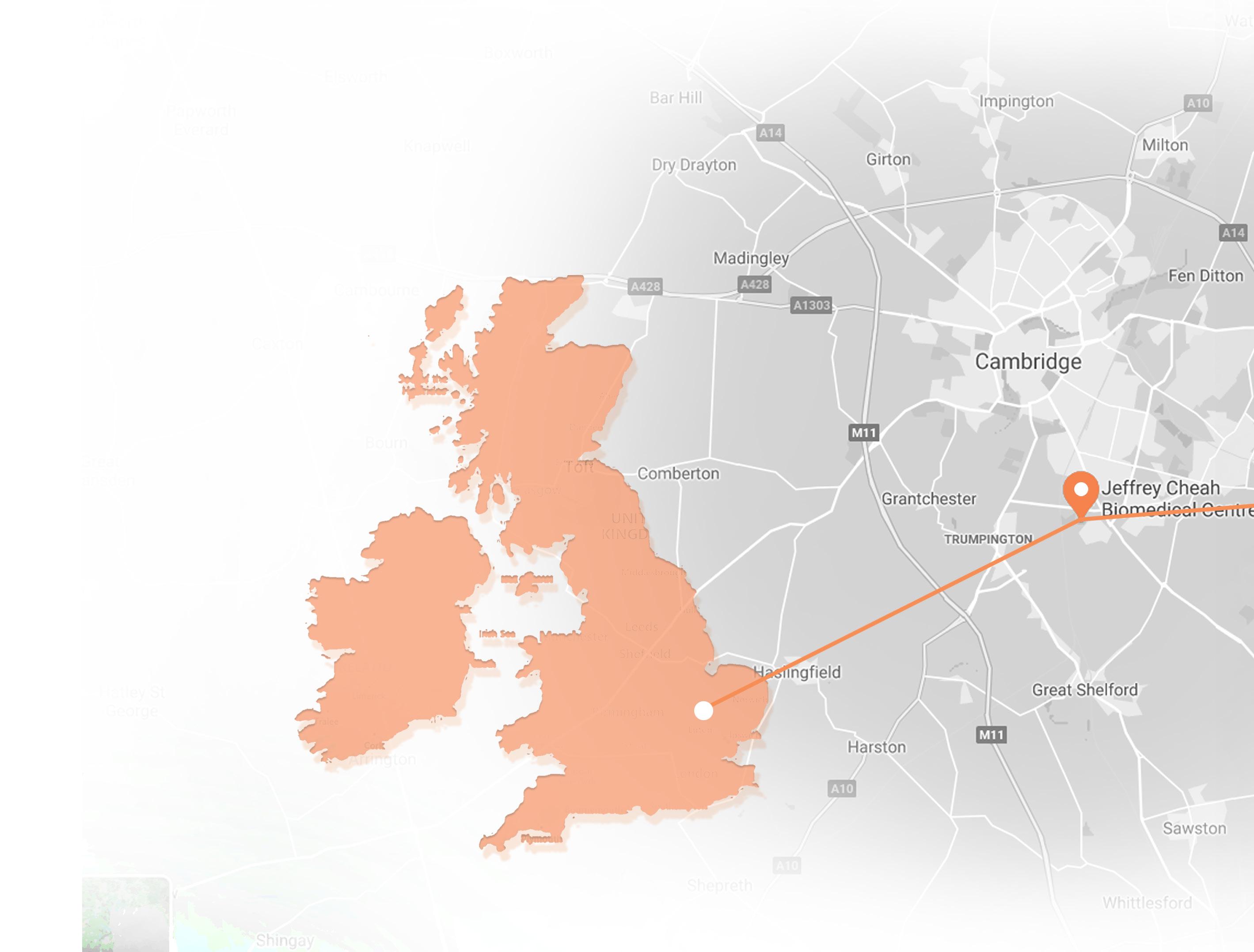
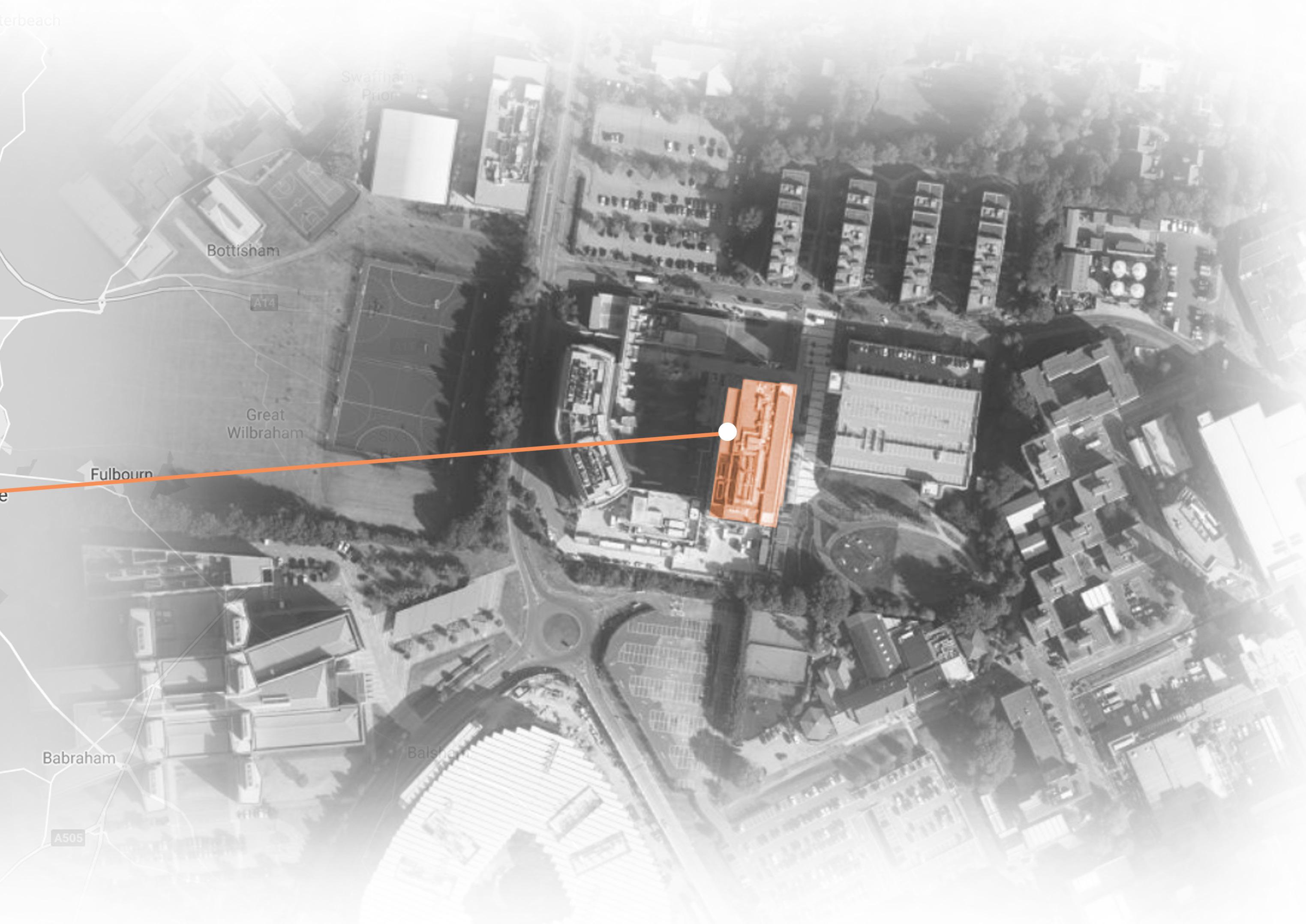
Project Capella is located within the Cambridge Biomedical Campus, in close proximity to other existing and operational buildings. Following its completion, the building was renamed Jeffrey Cheah Biomedical Centre.
Jeffrey Cheah Biomedical Centre, Puddicombe Way, Cambridge, CB2 0AW

Cambridge Academy for Science and Technology
Cancer Research


UK Cambridge Institute
 NHS Hospital Staff Car Park
Jeffrey Cheah Biomedical Centre
AstraZeneca PLC
Puddicombe Way
NHS Hospital Staff Car Park
NHS Hospital Staff Car Park
Jeffrey Cheah Biomedical Centre
AstraZeneca PLC
Puddicombe Way
The PCE HybiDfMA System philosophy combines Offsite manufactured structural components with in situ concrete creating a flexible design approach for any frame configuration, resulting in high quality, fast build innovative solutions and thus providing the client with exceptional value.
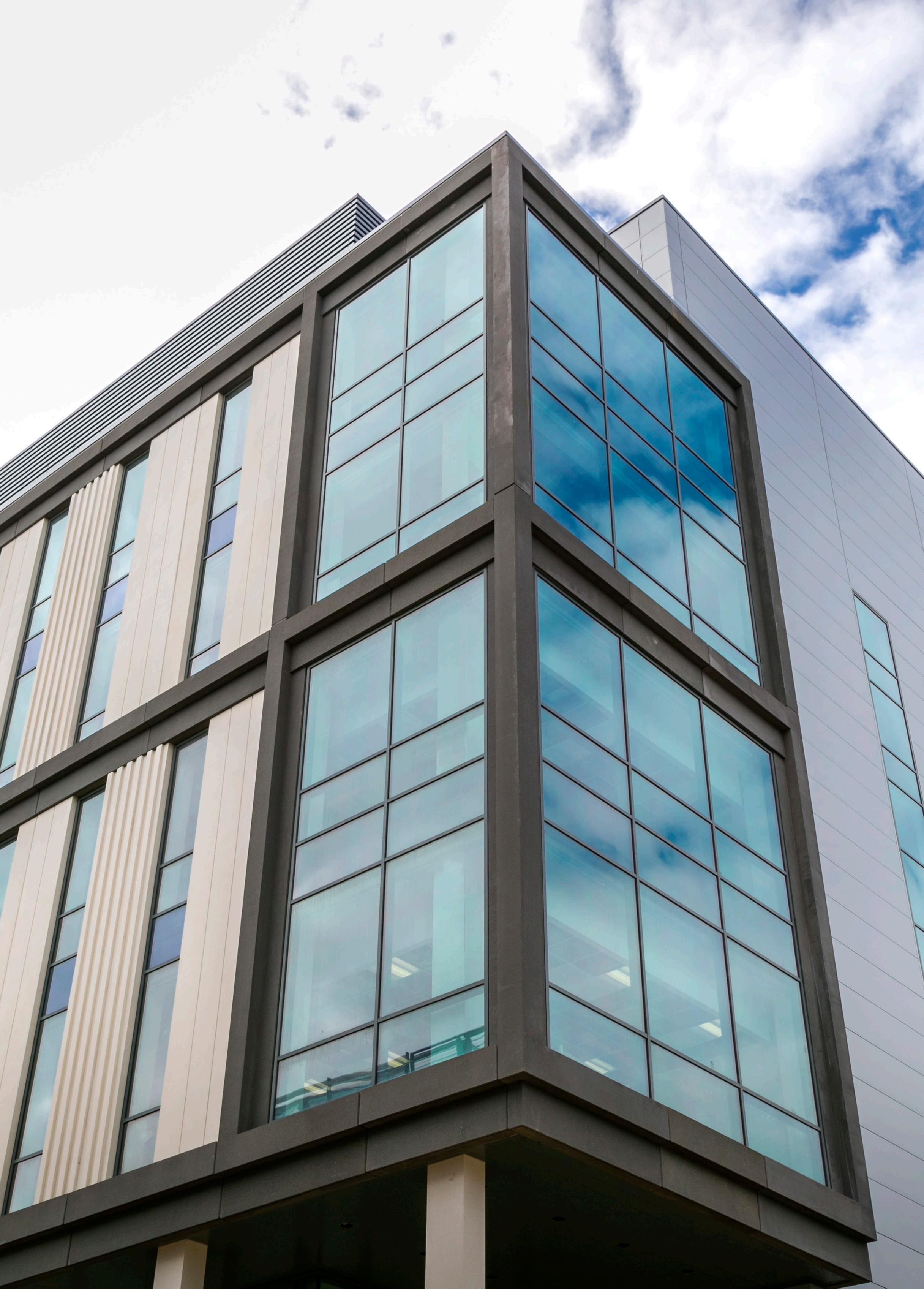
The structural solution for the Capella laboratory project comprised over 4,150 precast concrete components that included over 1,000 columns, beam and wall units, 1,5000m² of hollowcore flooring units along with 56 large volumetric box units and 89 stair and landing units, together with just over 4,000m³ of in situ reinforced concrete.
The offsite HybriDfma design solution for this project has proved that a primarily concrete ‘kit of parts’ approach to construction enables successful construction of very complex projects, allowing exacting technical requirements, including those more stringent than normally required to be achieved in challenging locations.
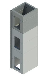
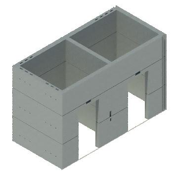
The offsite factory production of the stair and lift shaft boxes ensured the critical internal dimensional accuracy was maintained within the tight tolerance requirements of the finished core structure. Construction of the Capella Laboratory progressed rapidly because of the adoption of PCE Ltd’s fast erection programme, which was much shorter than would otherwise have been possible.
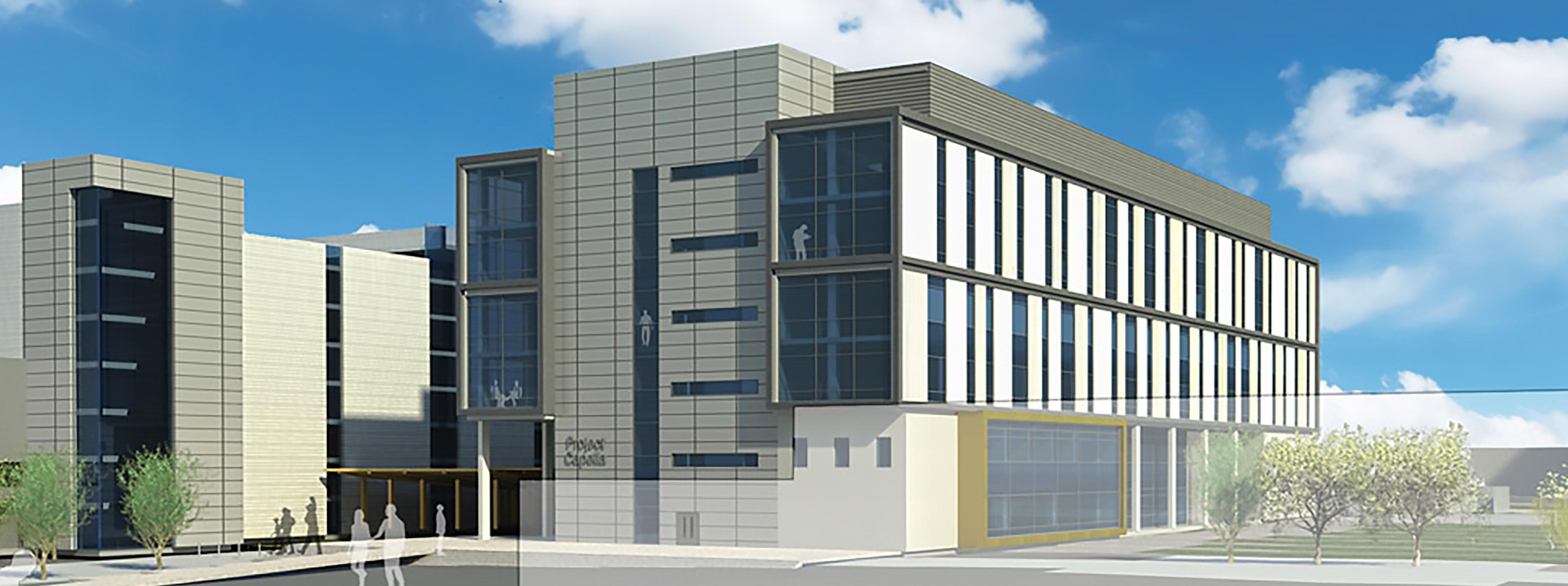
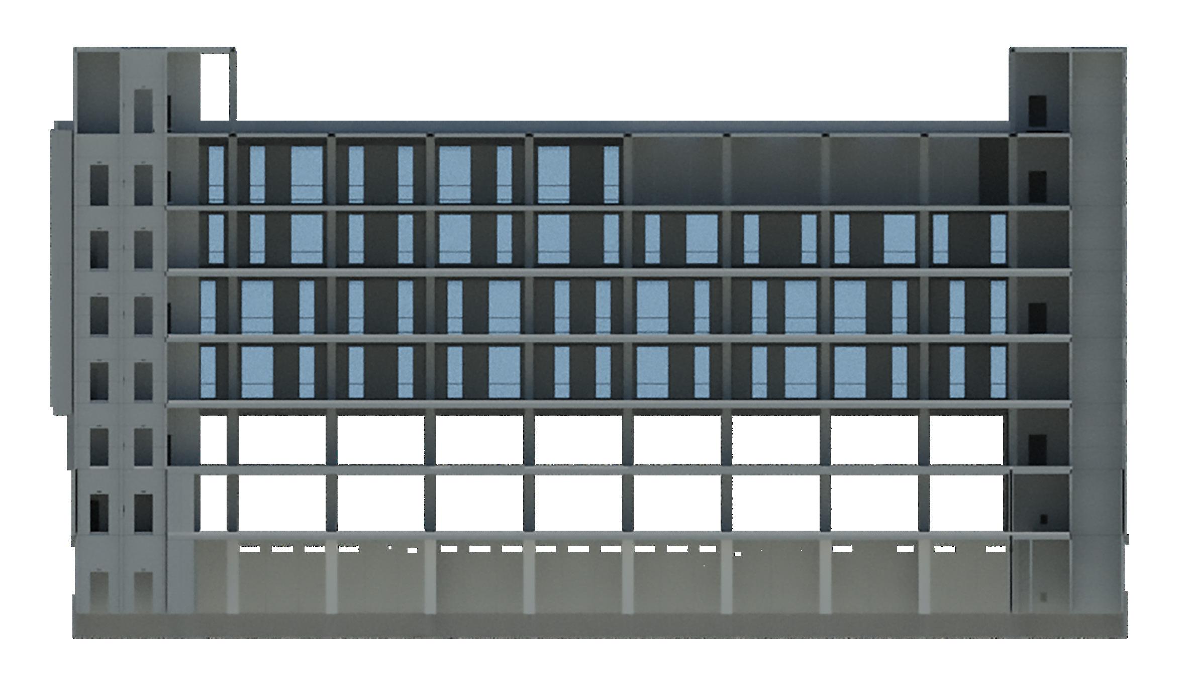

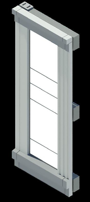
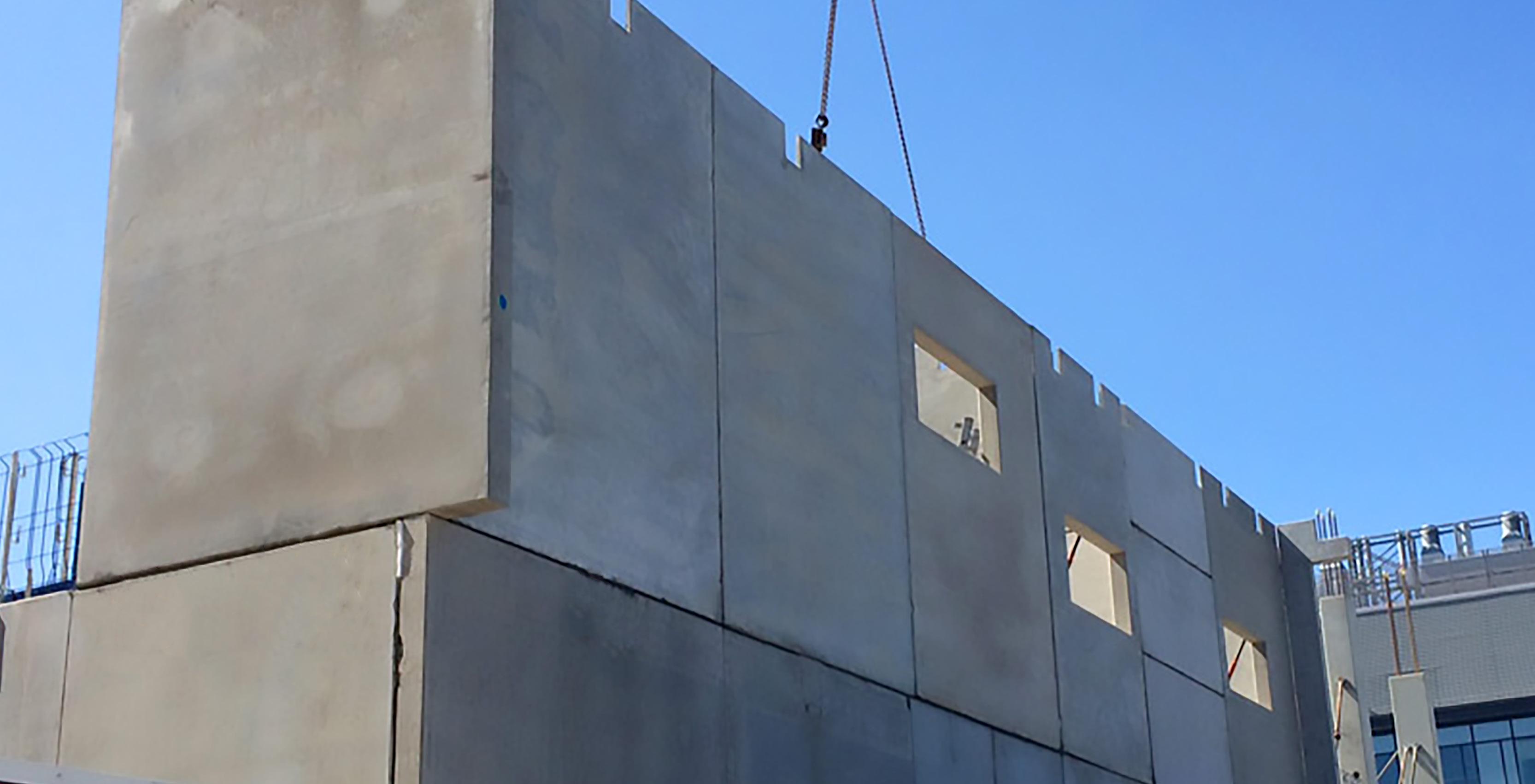
10-metre-high offsite constructed external pre-glazed panels installed at a rate of 300m² per day.

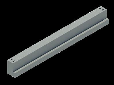
Precast Concrete edge beams were used to simplify interfaces with the façade whilst efficiently controlling deflection limits.
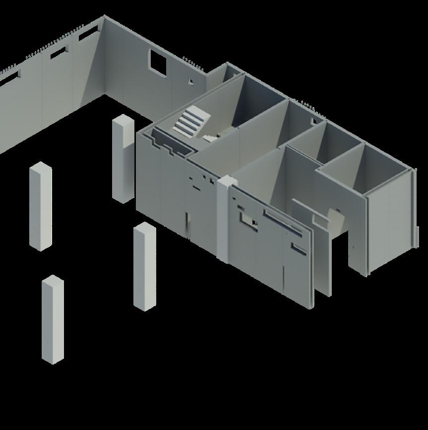
Providing stair and lift shafts as well as frame stability.
Up to 5.0m high for basement construction and floor to soffit heights within the frame.

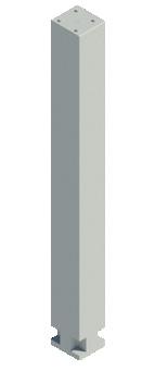
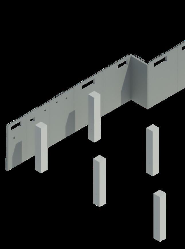
Precast concrete columns were a key part of the structural frame design adopted.
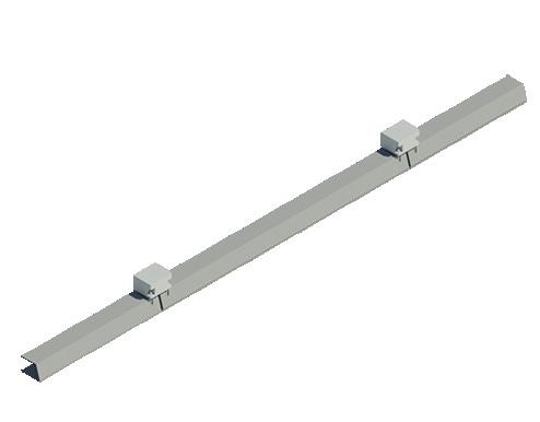
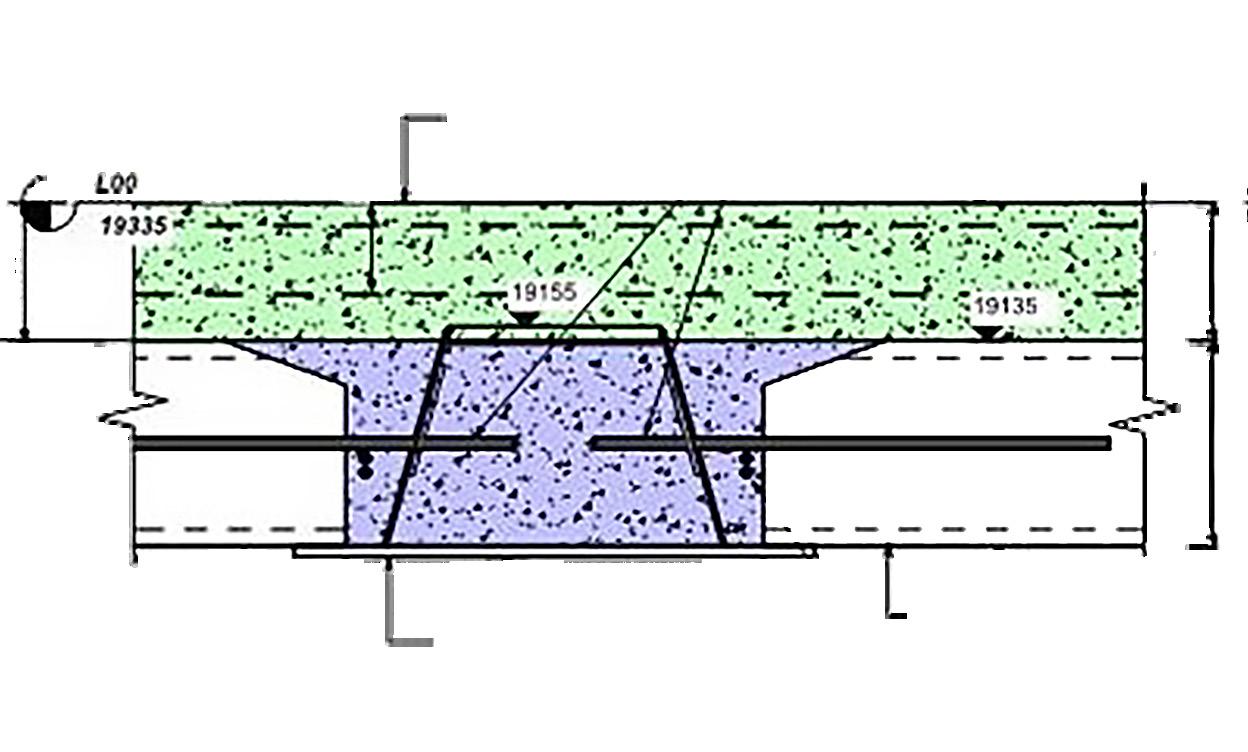
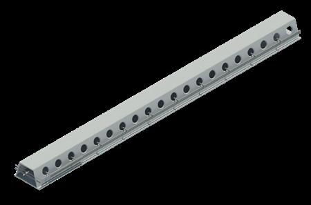
Delta Beams used compositely with reinforced structural concrete to support the floor structure without any down stands.
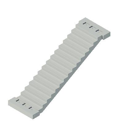
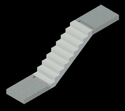
Stair flights with pre-fitted hand rails were installed.
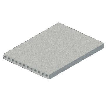
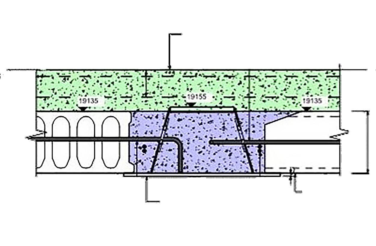
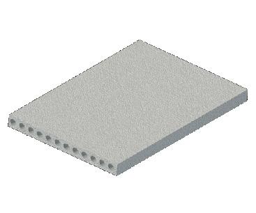
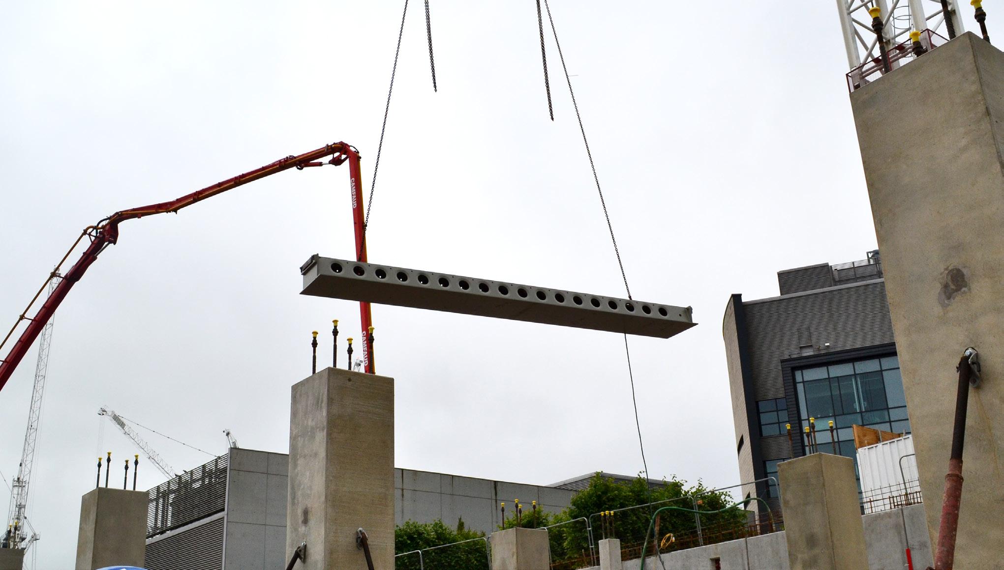
300mm deep prestressed concrete hollowcore units, designed to work compositely with the 200mm deep reinforced structural topping.
The Capella Laboratory structure was delivered in conjunction with PCE’s Digital Delivery Strategy protocols providing Level 2 BIM compliance along with a digital management strategy which also provided real time data at every stage of the process.

BIM modelling was used to collate and display intelligent data about each component part along with the status of that component at any stage of the project. This strategy ensured the integrity of the design data along with providing the project teams with the means to make informed decisions throughout the duration of the project.
The use of BIM was significant in ensuring that the risk of any clashes between the structure and services were eliminated before construction commenced and that accuracy of fit of components was maximised to provide the high-quality requirements for the structure, including basement, allowing the integration of an extremely complex services strategy.



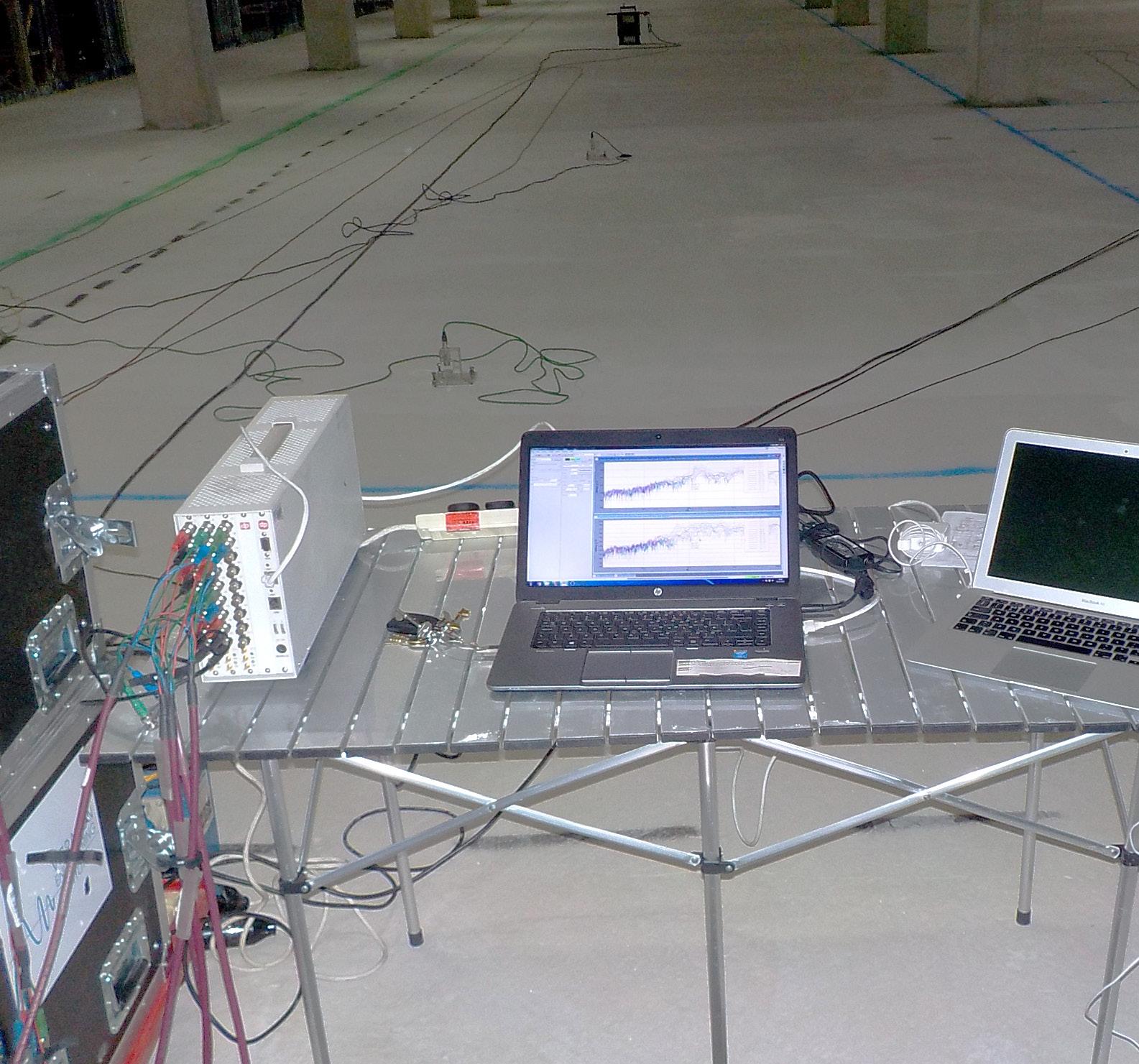
To ensure the exceptionally low design vibration criteria was met, PCE employed University of Exeter‘s Head of Engineering, Professor Paul Reynolds, a leading world specialist in the field of structural vibration for specialist advice and full-scale test procedures as doubts had been raised as to whether an offsite construction solution would be able to meet the vibration requirements compared to a monolithic in-situ concrete solution.
To prove the exceptionally low vibration requirements had been met, a fullscale test of the dynamic properties of one of the floors after construction was carried out by Full Scale Dynamics using an array of shakers and accelerometers coupled with specialist software. The results clearly showed that the PCE HybriDfMA Frames System solution adopted gave a much stiffer floor plate than predicted using typical conservative design assumptions.

The final PCE composite floor plate solution also reduced the self-weight from 11.25kN/m² for an in situ concrete solution to only 9.0kN/m², resulting in a project saving of over 3,500 tonnes of insitu reinforced concrete.
Post Completion VC
spectrum analysis on level 1
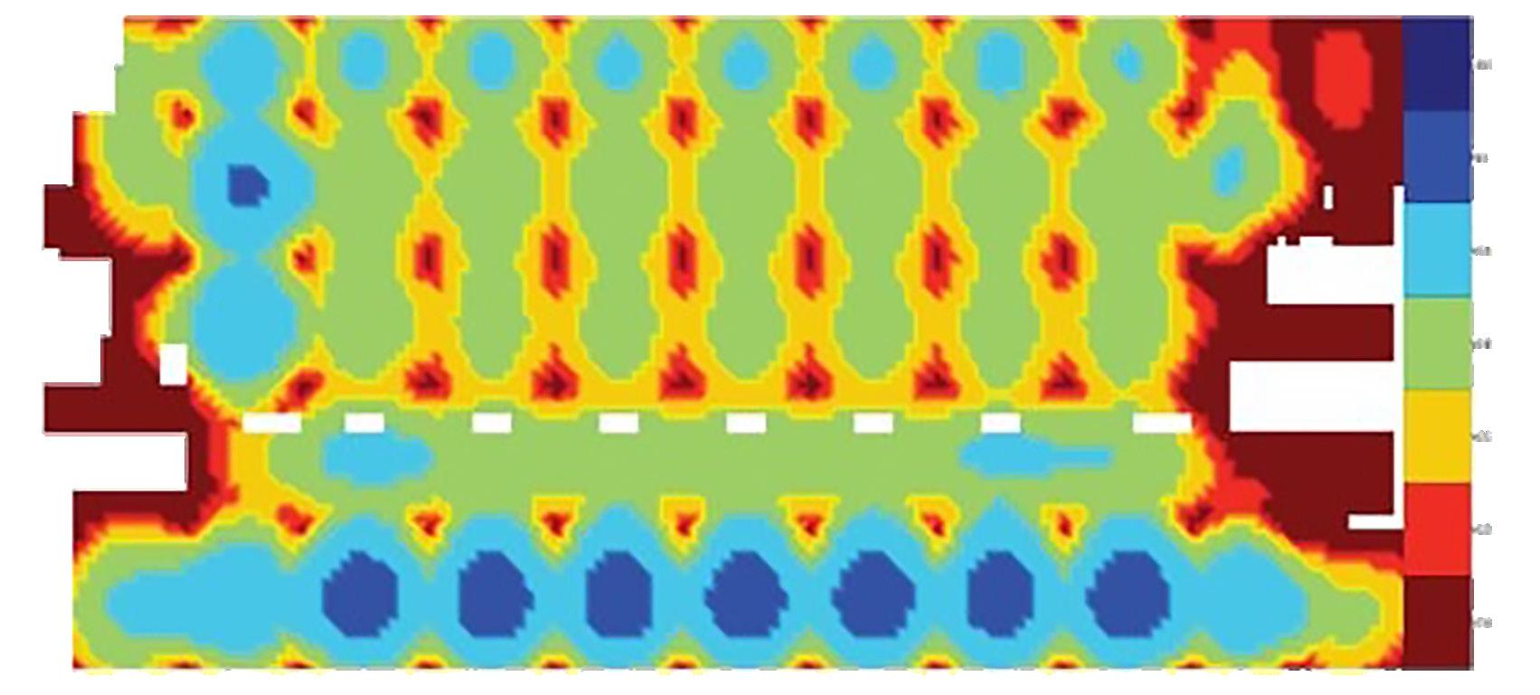
VC-A to laboratory spaces and RF-8 to ‘write-up’ spaces
Volumetric precast concrete box modules, were utilised from start of the assembly process lift and stair cores.
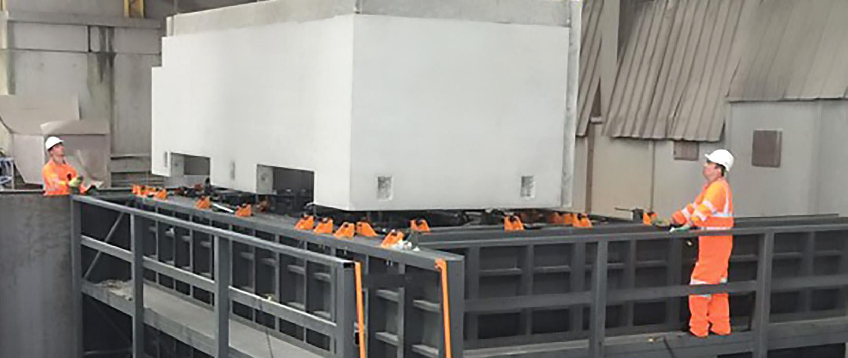
Constructed to the full height of the building gave a significant time saving but also provided and egress of site personnel to the floor levels progressed.
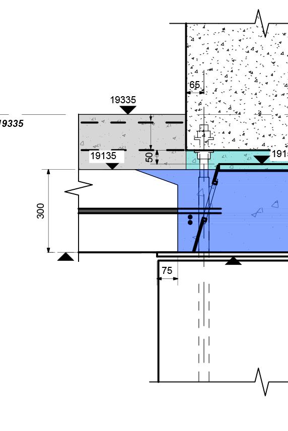
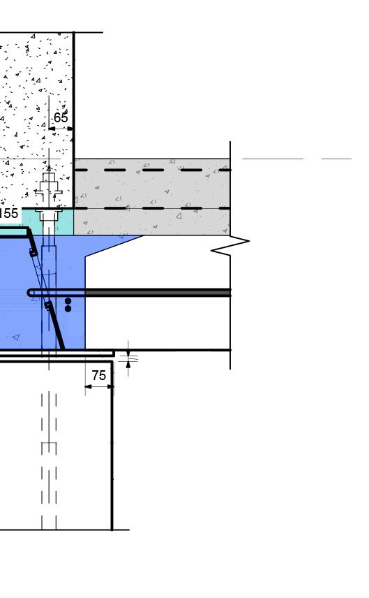
shoe detail by PCC designer
Reinforced concrete topping
Composite Deltabeam by PCC designer
Columnmodules, cast as a single unit, process to form the building they not only provided safe access levels as construction
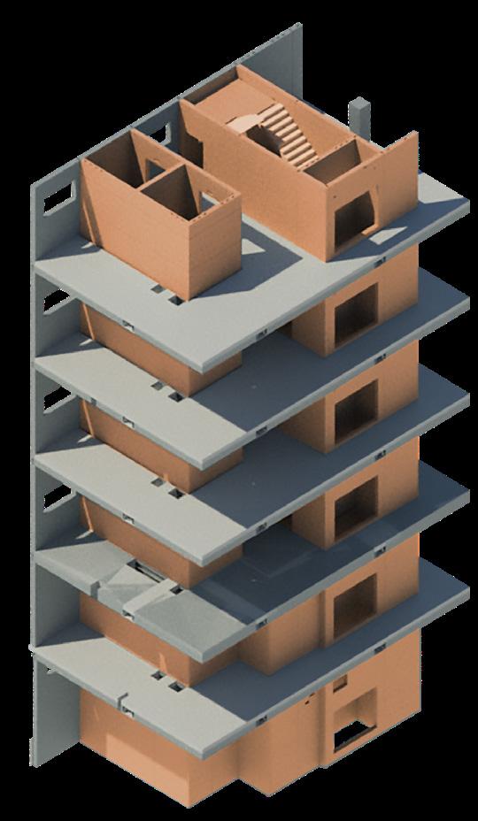
Core Walls provide Lateral Stability. Continuous through building.

Transverse reinforcement for composite action and robustness by PCC designer
250mm deep
Precast Hollowcore planks by PCC designer

Steel packs
Reinforcement for secure and fire requirements by PCC designer
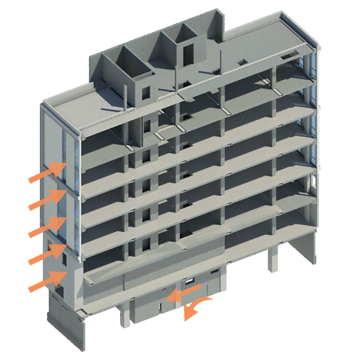
Lateral Loads
i.e. Wind, Thermal, Notional
Base shear and Moment at Foundations.
Slabs act as Stiff diaphragms to deliver horizontal loads to the stability elements.

Columns designed for vertical actions only.


Techrete
Cladding
Banagher
Columns, Edge Beams
Crofton
SWP
Stairs & Landings
Prefaxis
Twinwalls
Critical to the success to align the PCE ‘kit of parts’ requirements. assembled from especially relevant not allowing for
PCE Head Office Project Capella PeikkoSolid Walls, Hollowcore
Crofton Engineering
Structural Steel
success of delivering the project was supply chain partners with the requirements. The building was to be a just in time delivery process, relevant due to the tight site constraints for onsite storage of products.


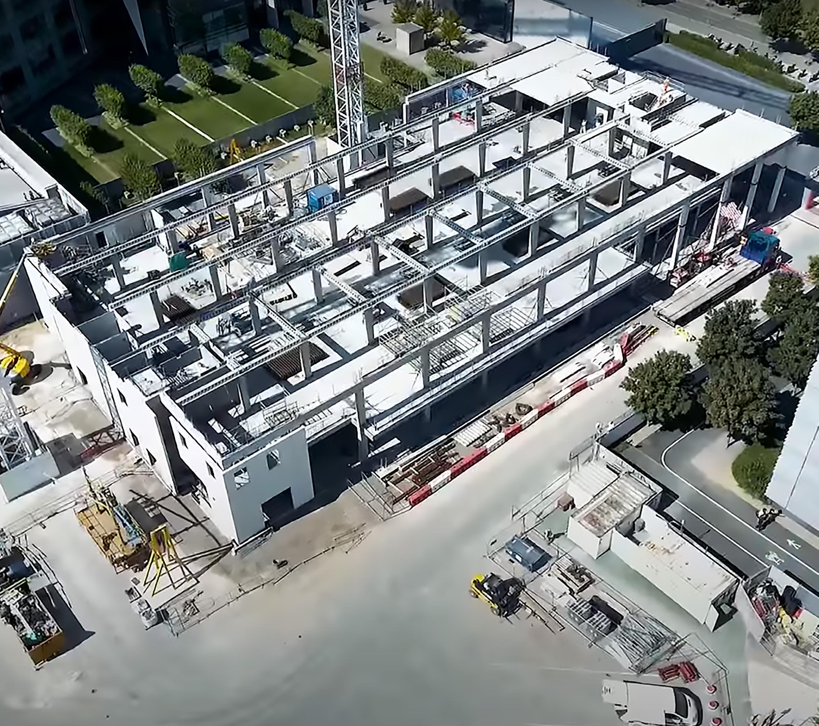
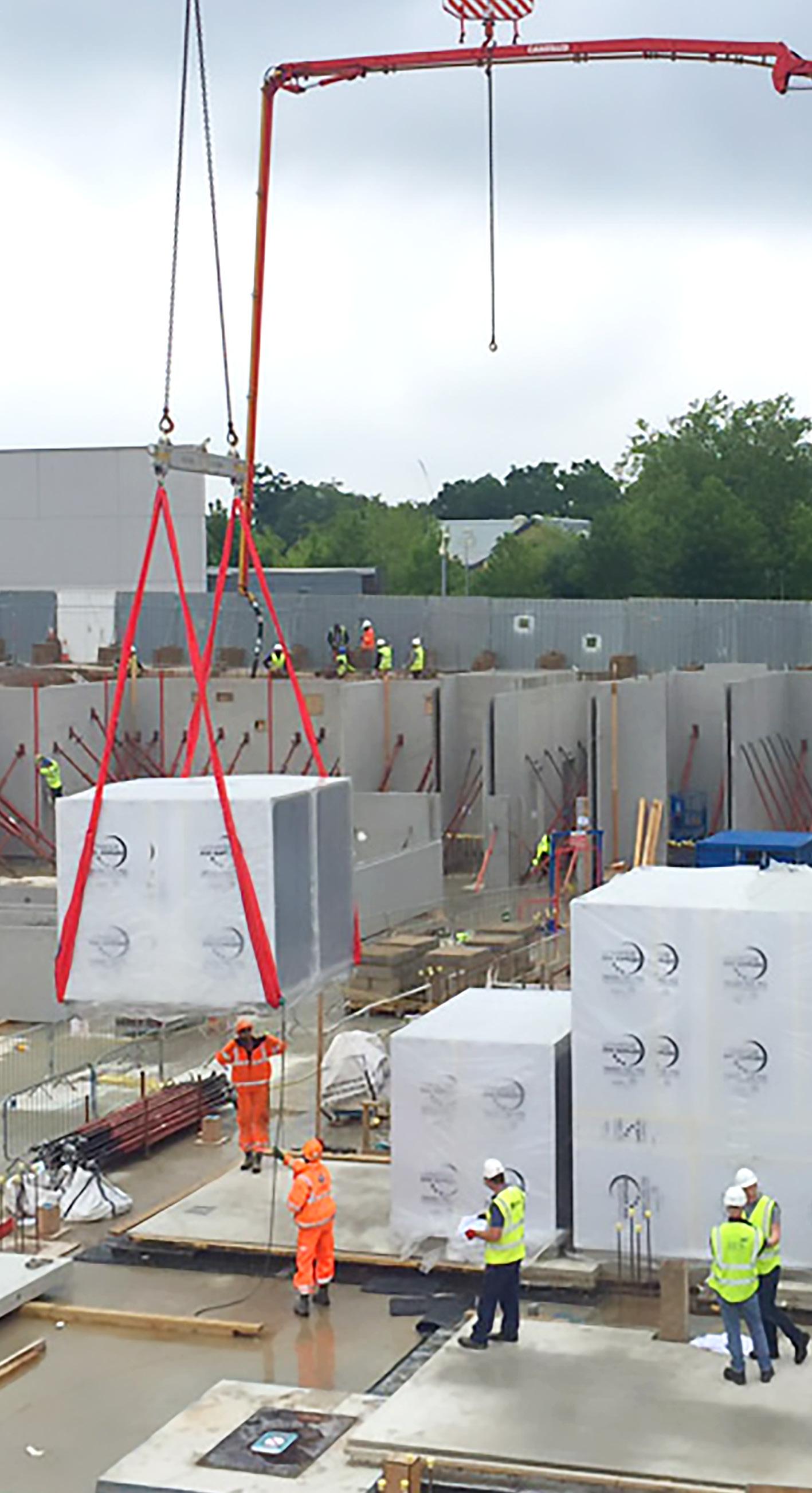
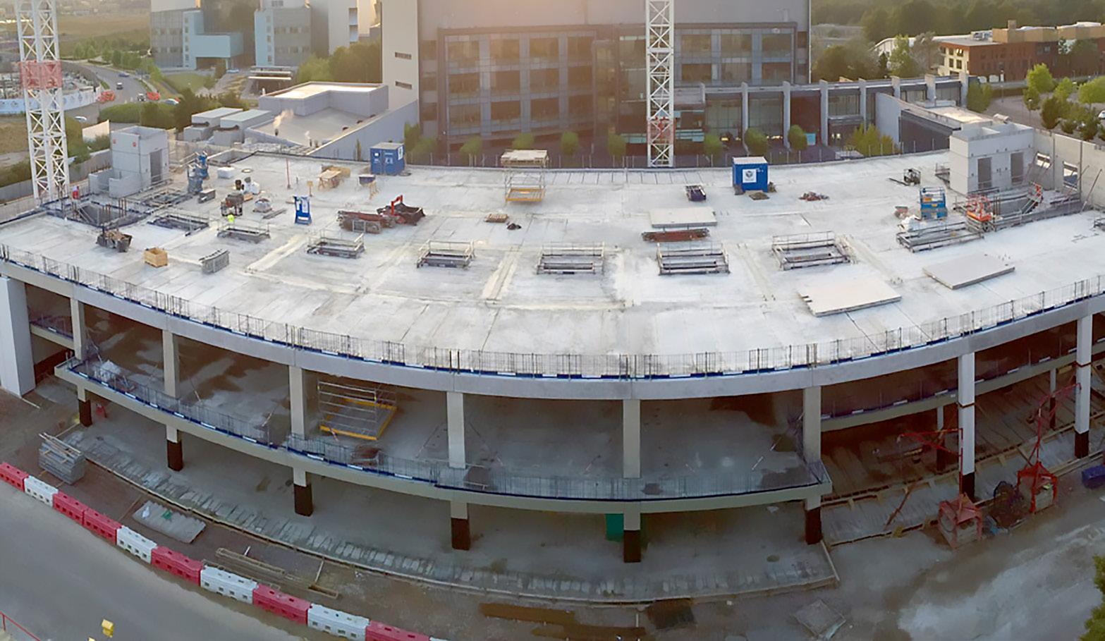
The structure was assembled using two tower cranes on a confined site with a relatively small footprint between two existing facilities that were in use. The HybriDfMA Frame approach reduced the onsite workforce required and the number of lorry movements.
The potential of physical and noise disruption to other users of the Cambridge Biomedical Campus, and the Addenbrookes Hospital, being greatly reduced as a result.
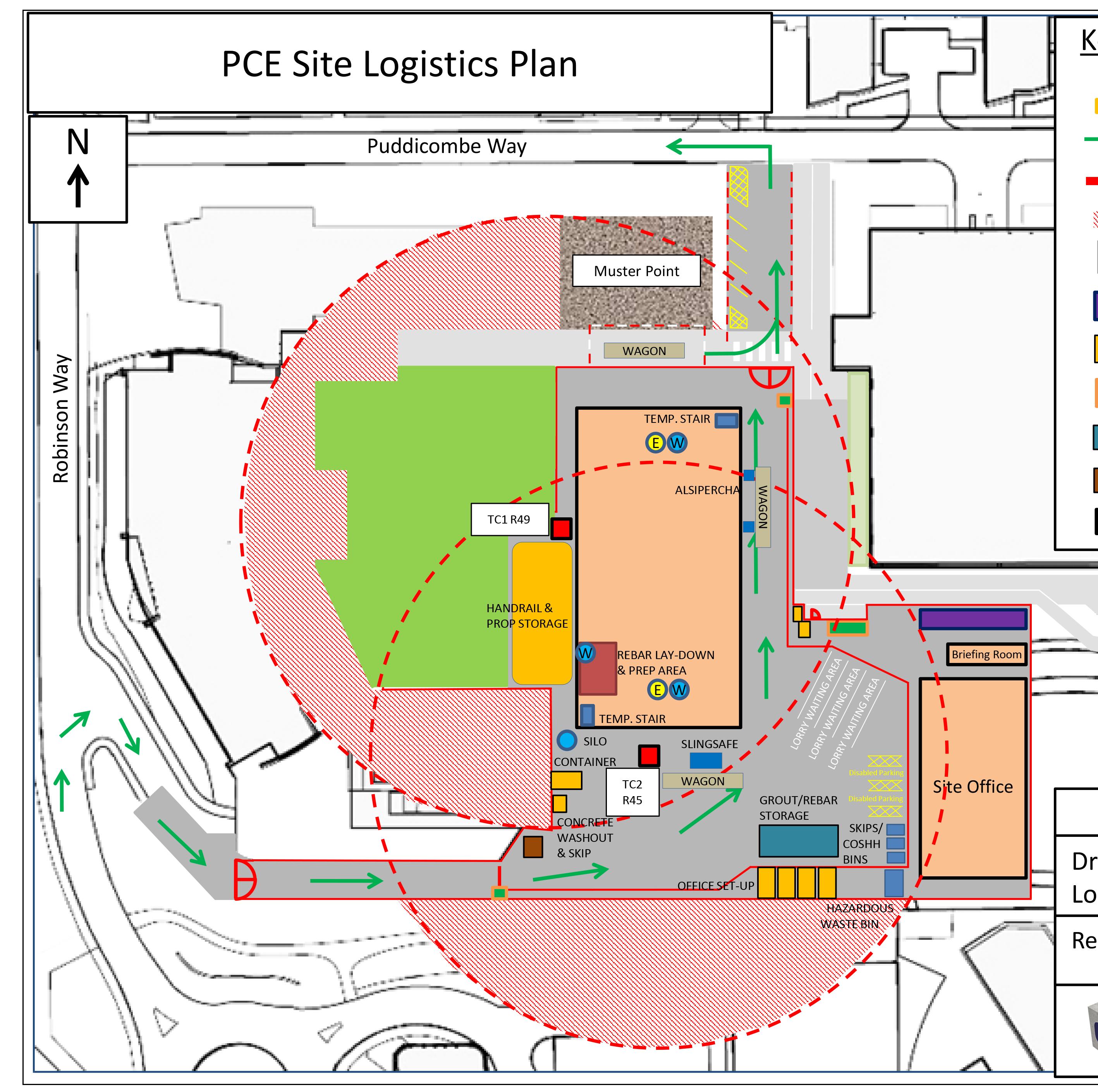
Just in time component delivery’s, loaded in accordance to a pre-determined loading plan to ensure the fastest and safest unloading method without any double handling of components.


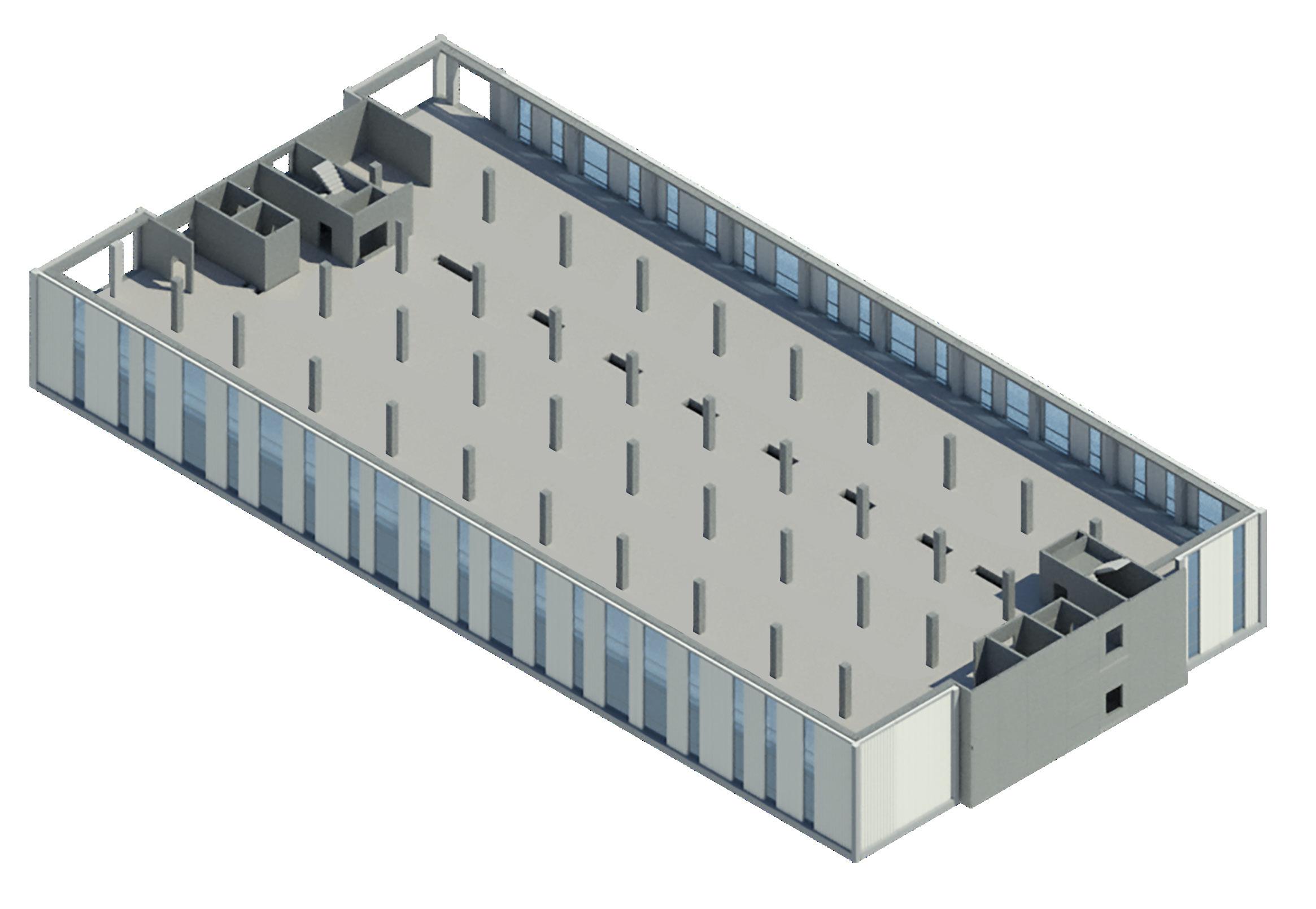
From the 3-dimensional componentised design model developed prior to commencement of offsite manufacturing, PCE Ltd were able to ensure the manufacture, delivery and assembly of over 4,150 individual structural components for the 7 suspended floors of the structure and basement walls in just 8 months of site activity.
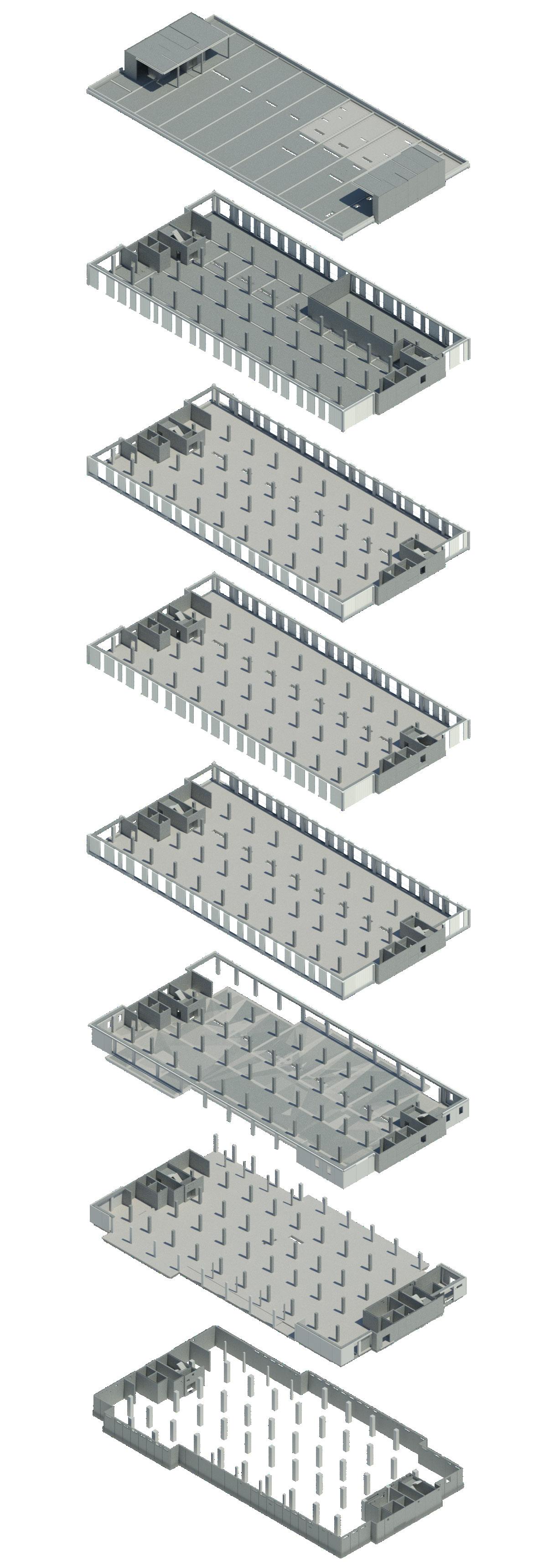

Fifth Floor
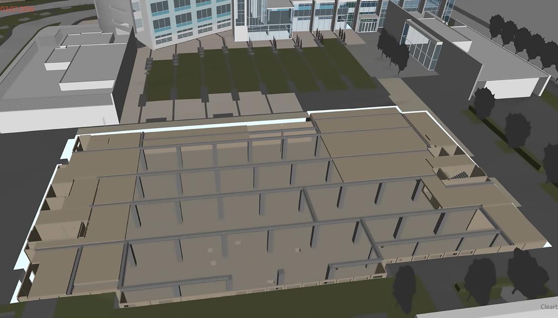
The floor plate construction beams, and structural reinforced concrete beam downstand

Fourth Floor
Spanning between concrete hollowcore 200mm of in situ
Third Floor
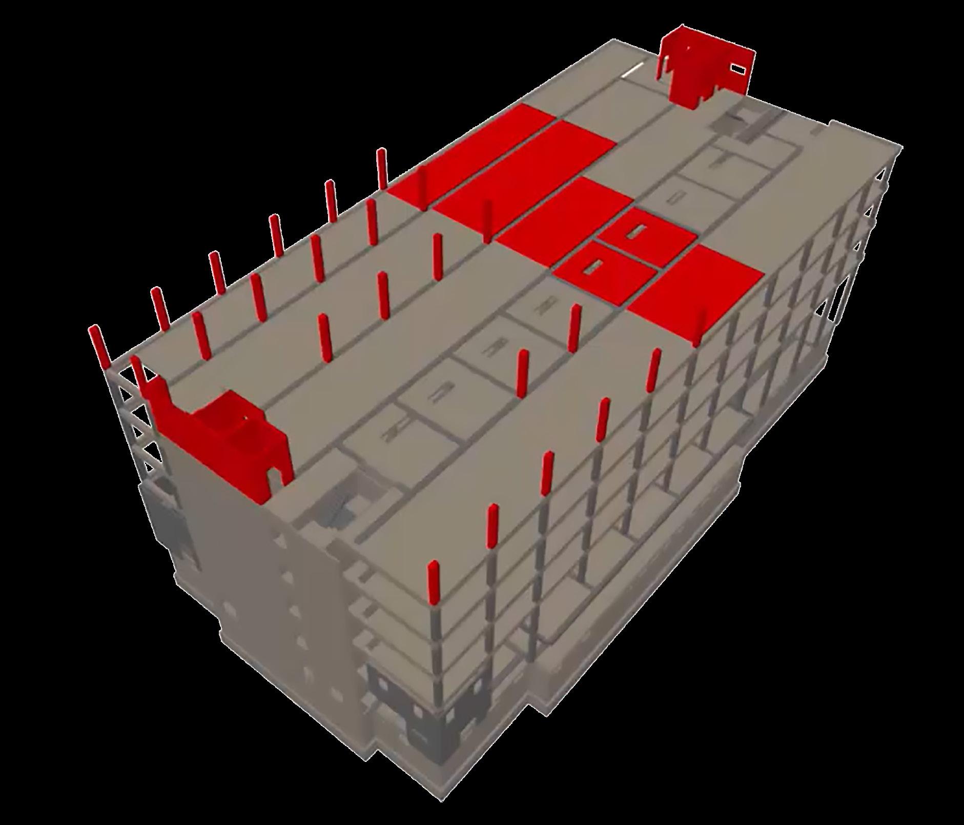
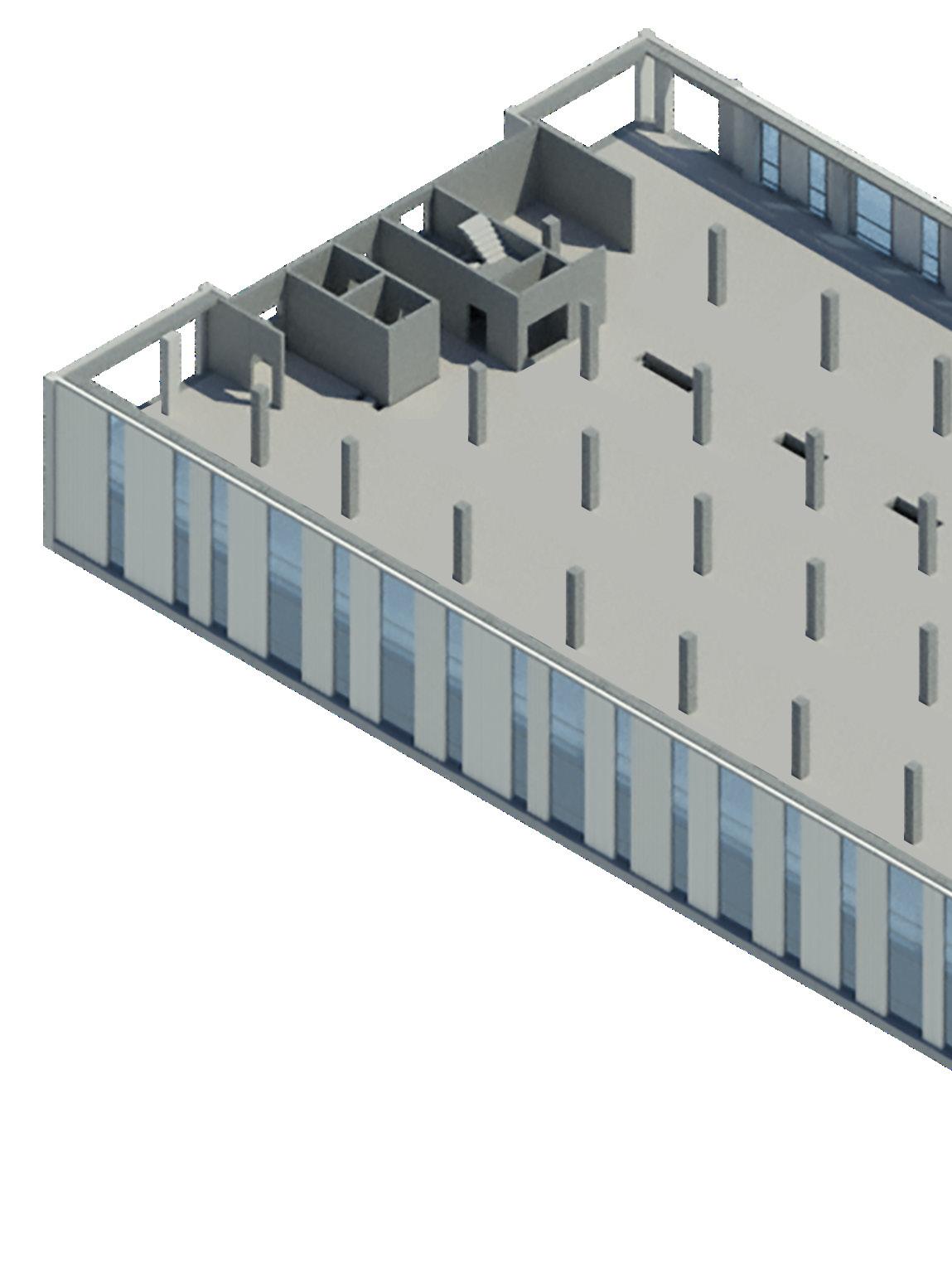
Layout of the beams accompanying image.
Second Floor
First Floor
Ground Floor
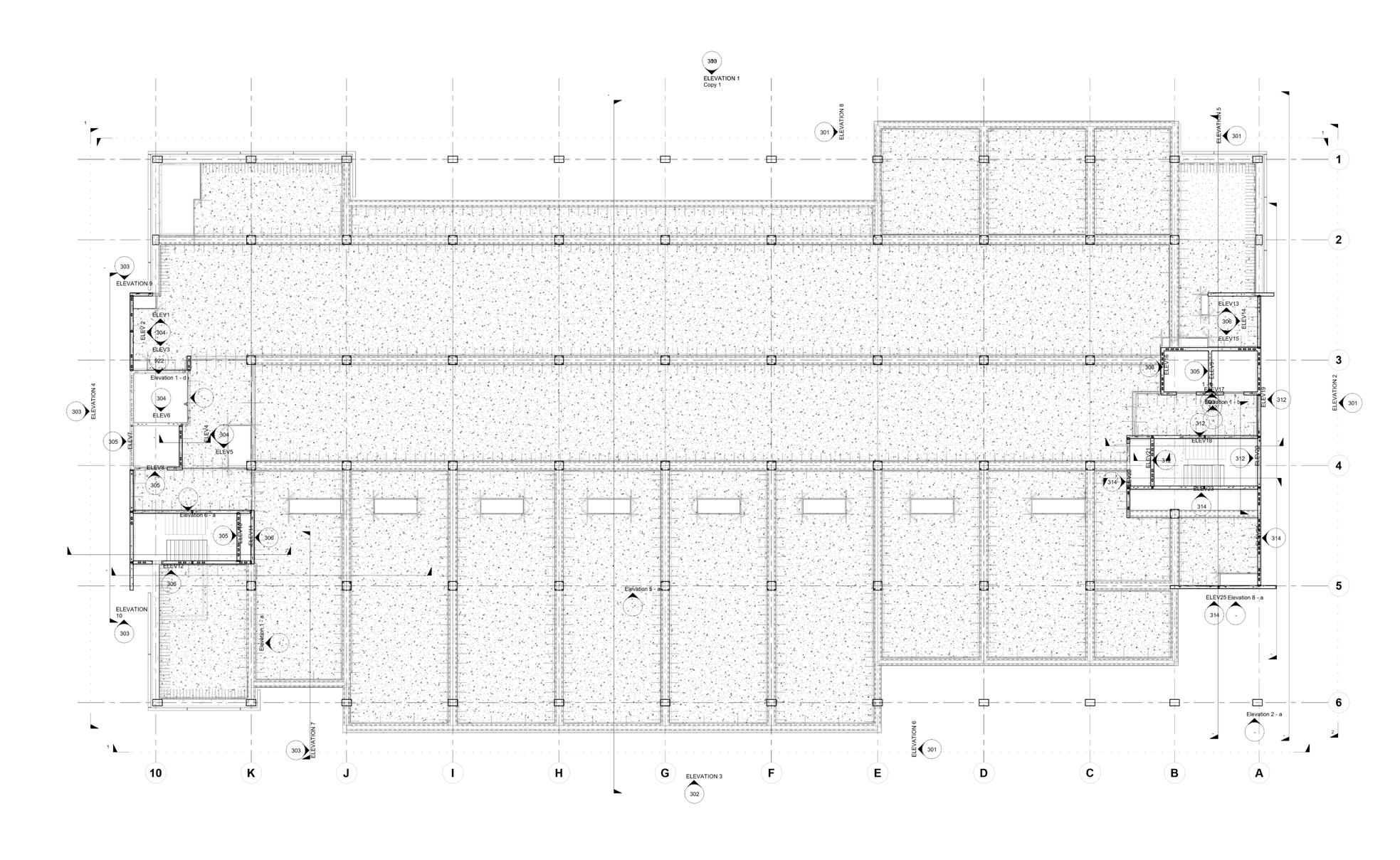
construction was formed by precast concrete edge structural steel Deltabeams working compositely with concrete for the spine beams thus eliminating typical downstand and providing a flat foor soffit.
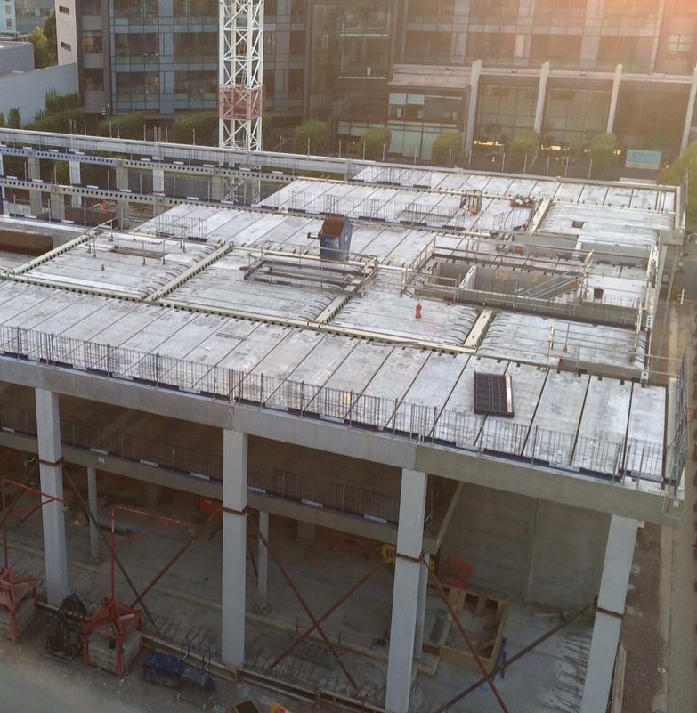
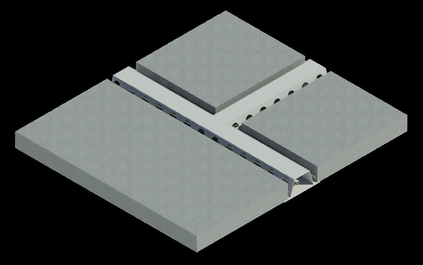
between the beams were 300mm deep prestressed hollowcore units designed to work compositely with reinforced concrete.
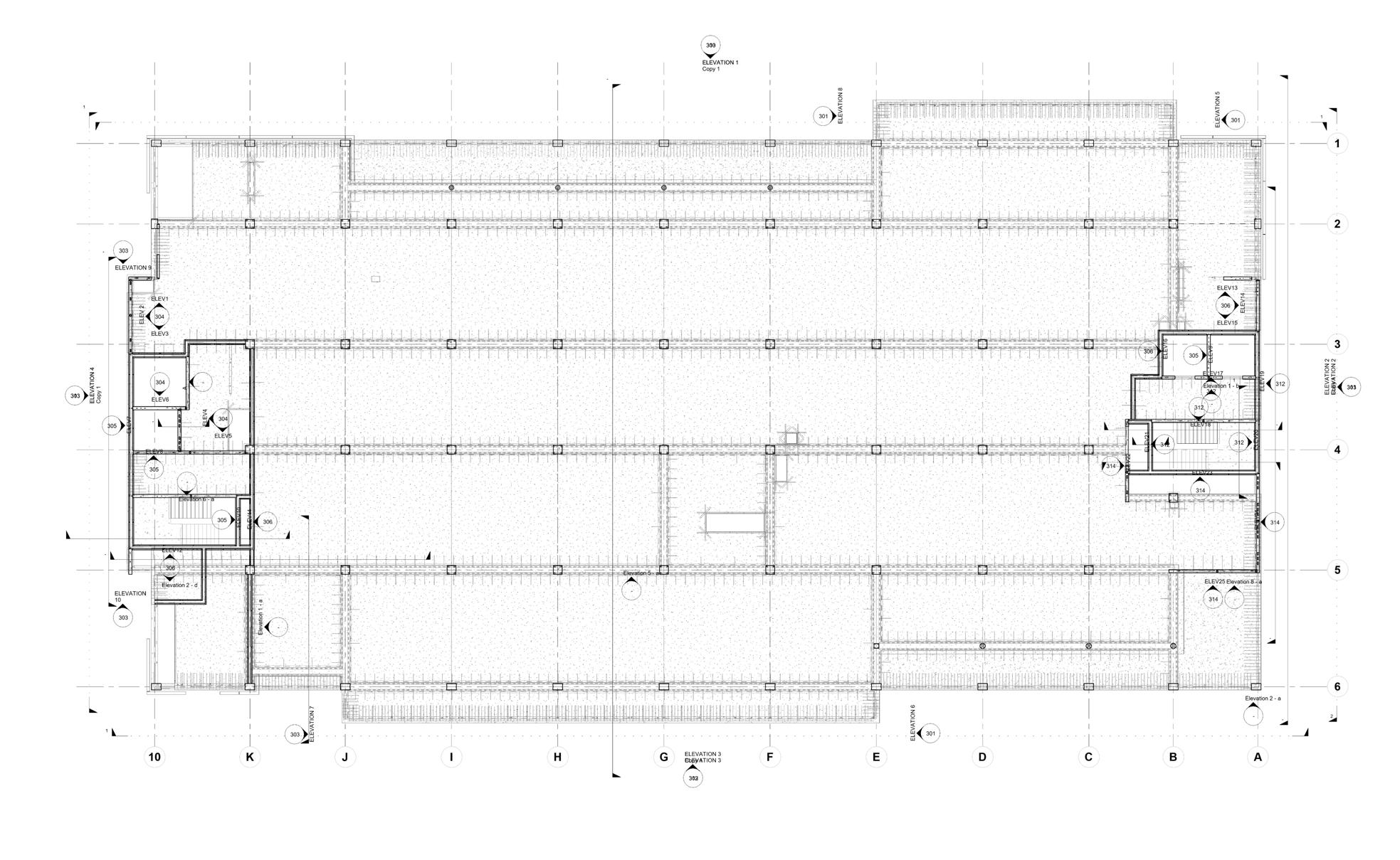
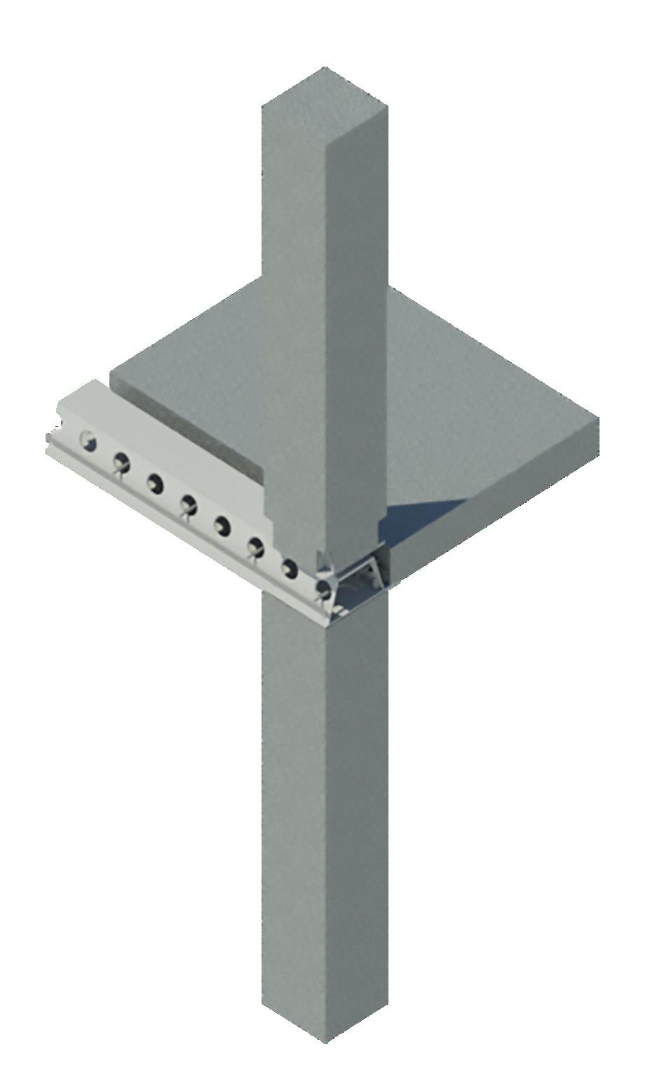
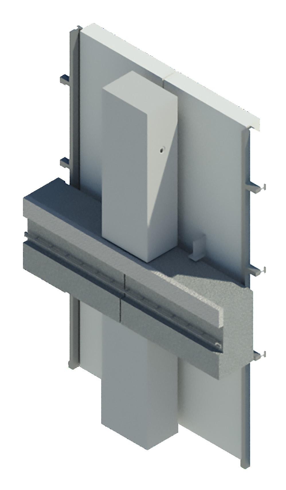
beams and floor units can be seen in the diagrams and image.
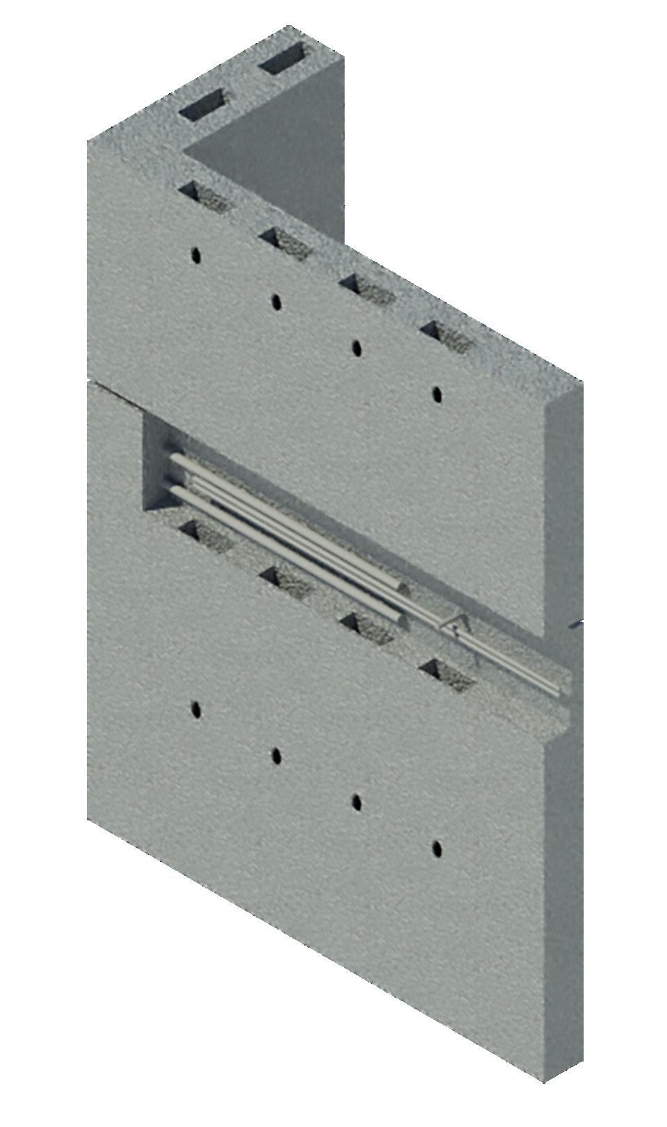
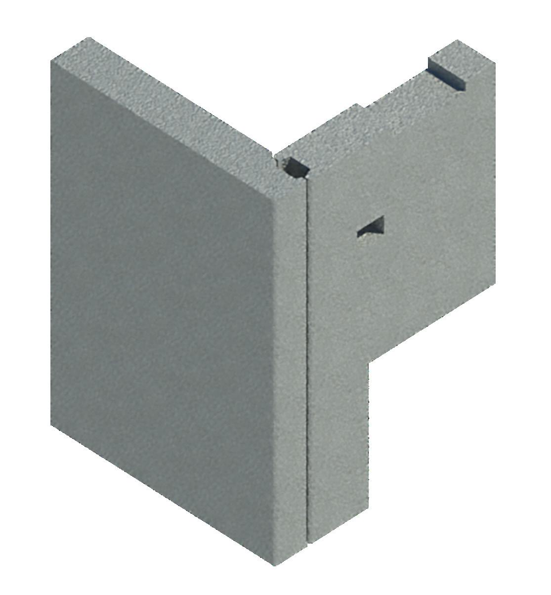
Connection between two Core Module Walls
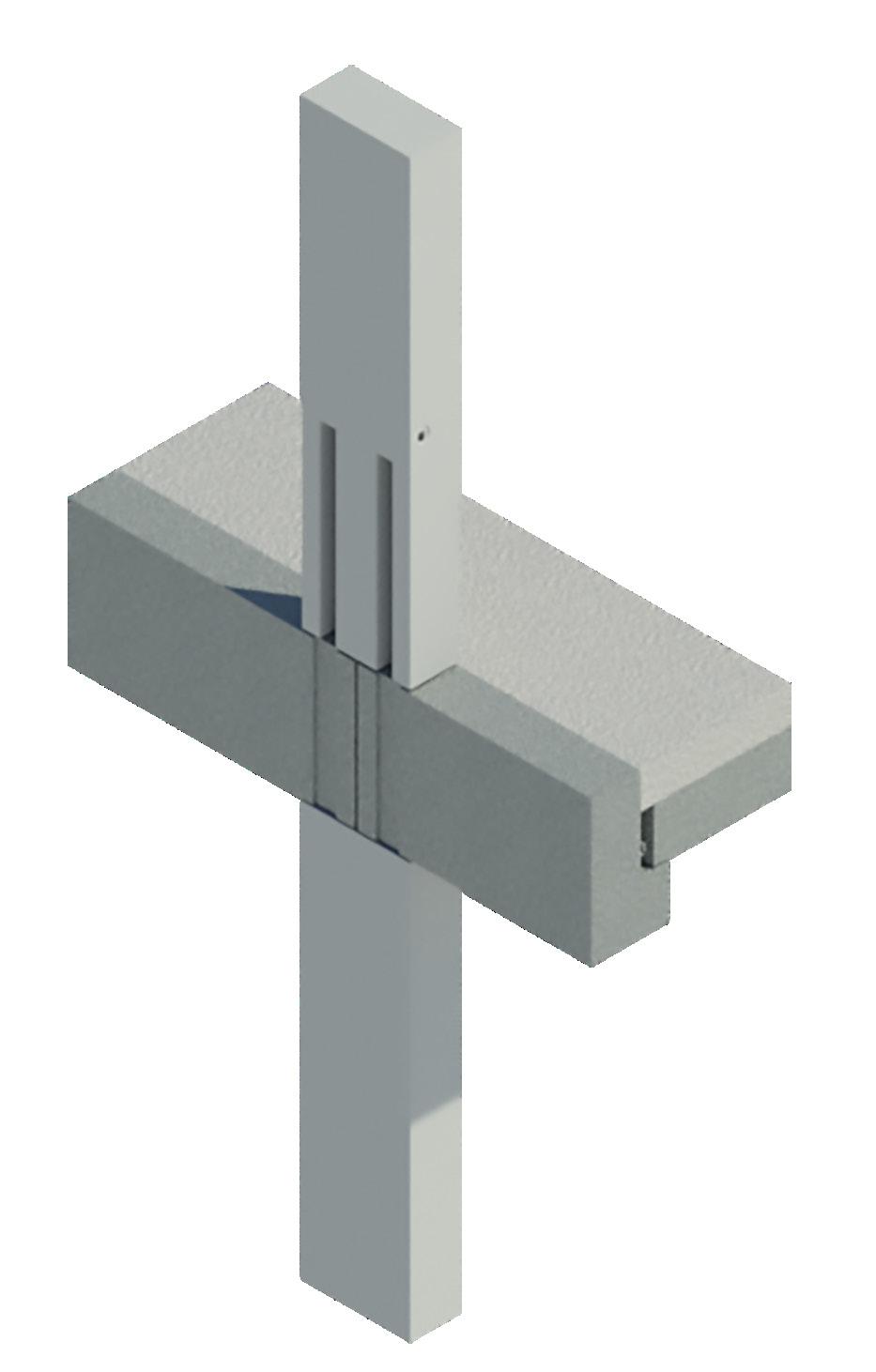
Edge Beam connection to Precast Concrete Columns

Deltabeam and Hollowcore detail
Deltabeam connection to Precast Concrete Columns

In situ Reinforced Concrete for structural composite action
Itegrated Facade Panel fixing onto building struture
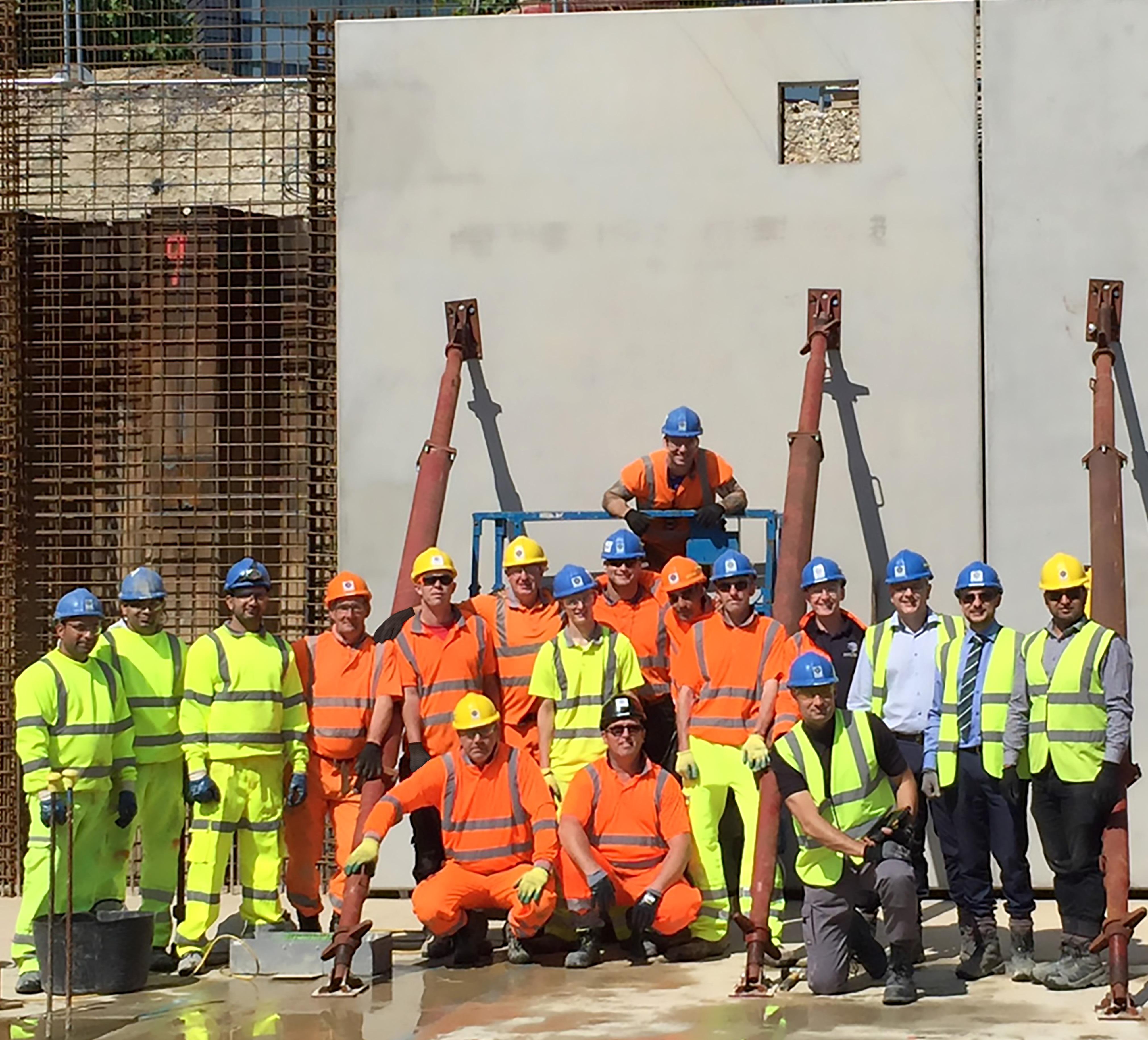
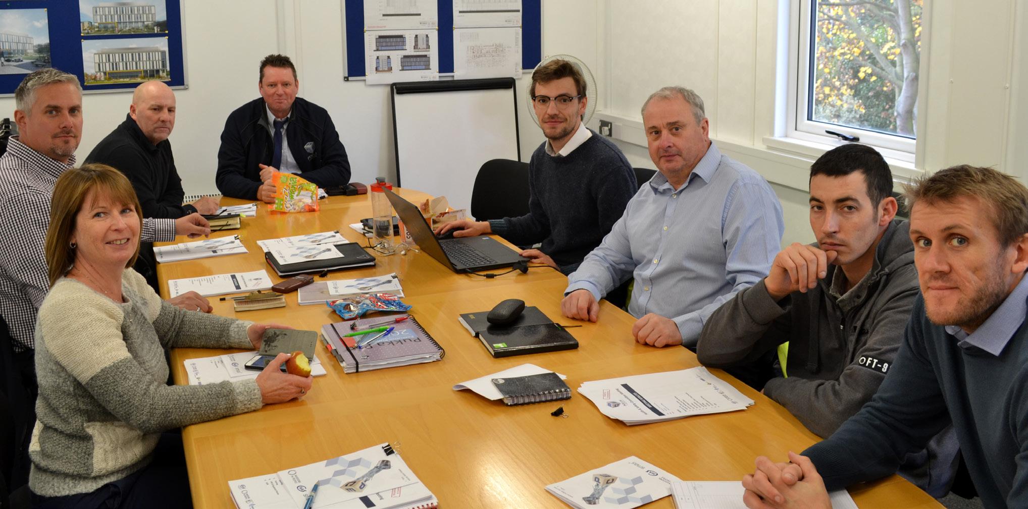
The image to the left shows PCE’s construction team celebrating structural component being a
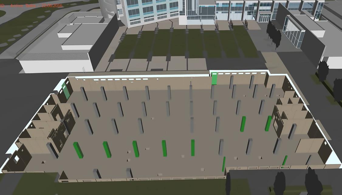
As with the complete assembly the basement components off slab. The process of assembly digitally predetermined and planned
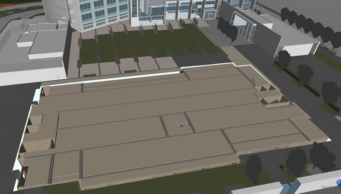
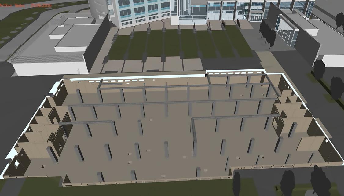
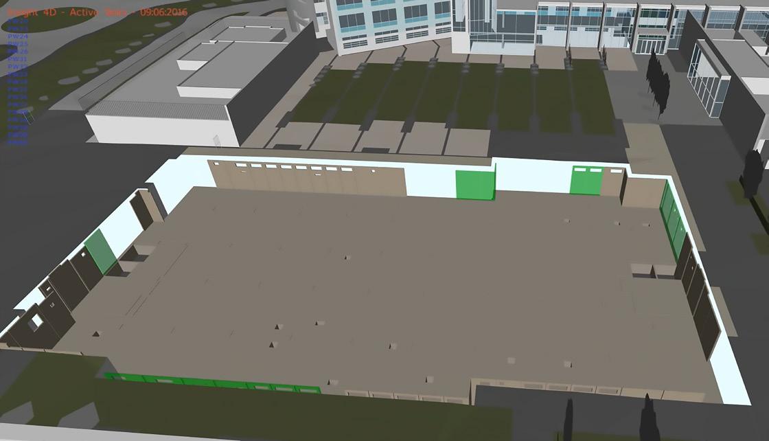
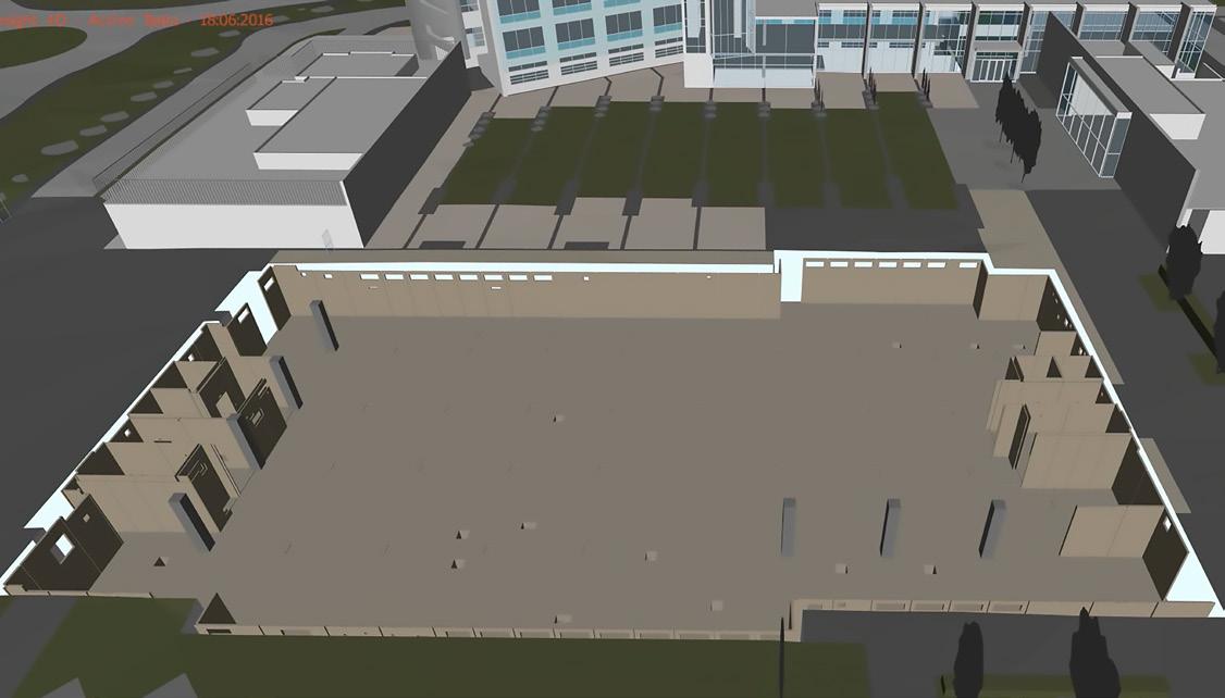 PCE’s Capella on site multi-disciplinary the erection of the projects first basement wall panel.


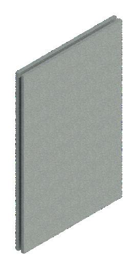
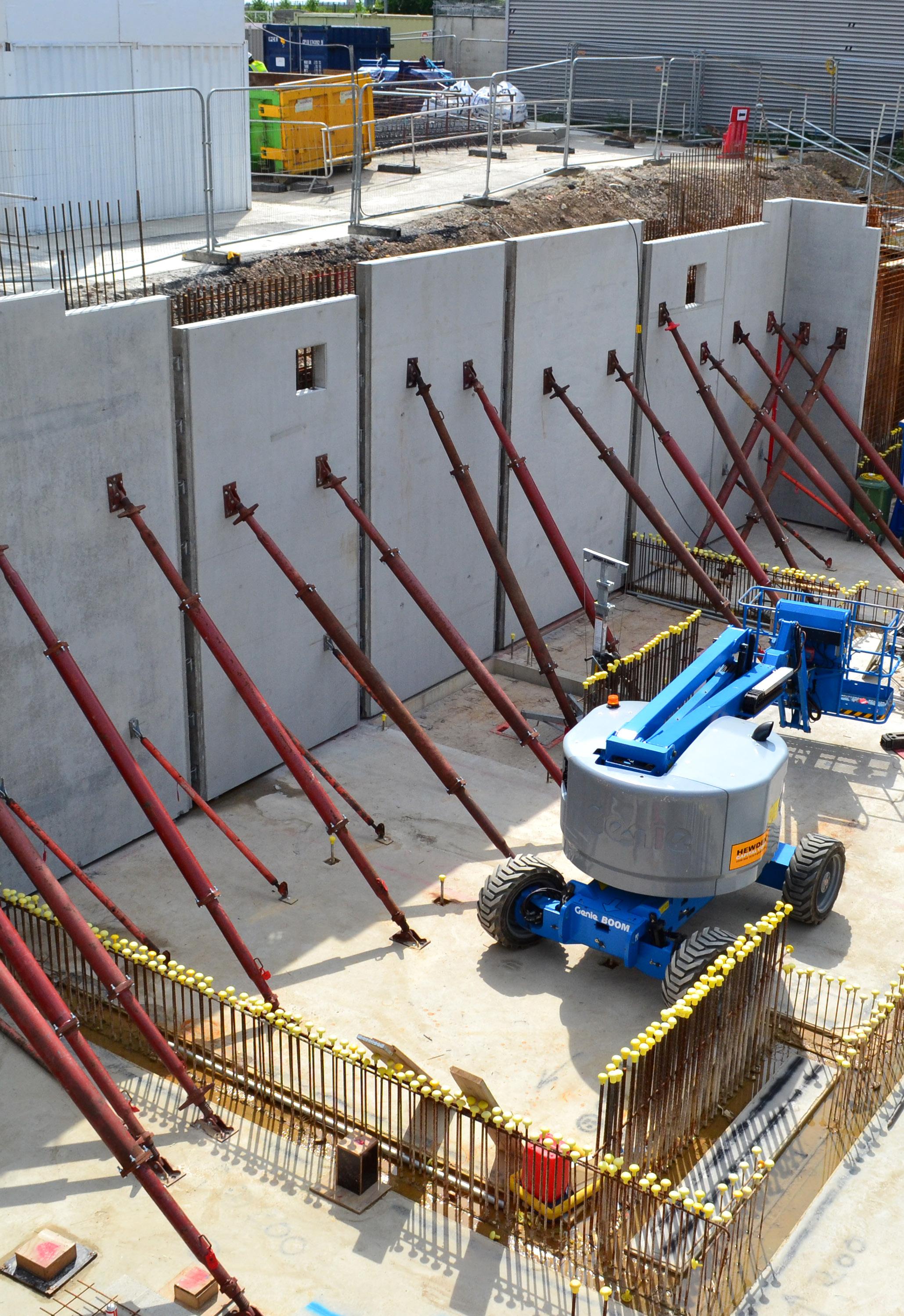
5-metre-high precast concrete wall panels were used to form the basement perimeter with in situ reinforced concrete infill in the cavity between the panels and the initial steel sheet piling.
A significant amount of the buildings necessary mechanical and electrical plant was lifted into place onto the basement floor prior to the suspended ground floor being constructed.



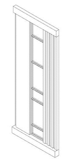
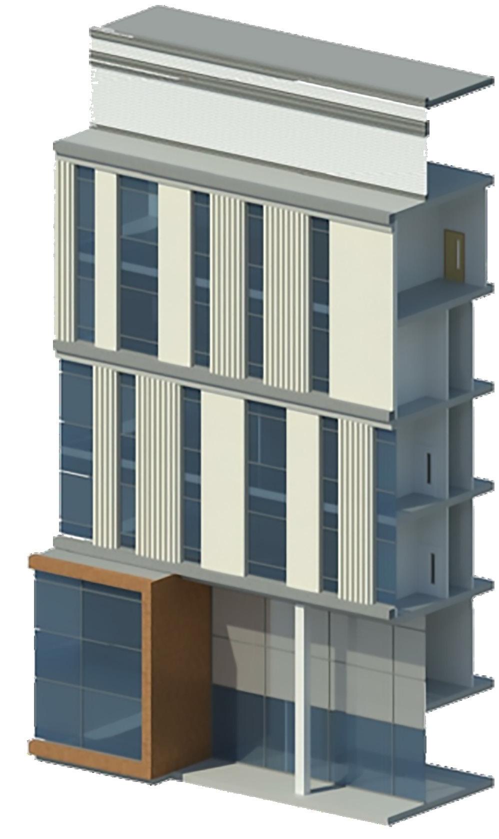

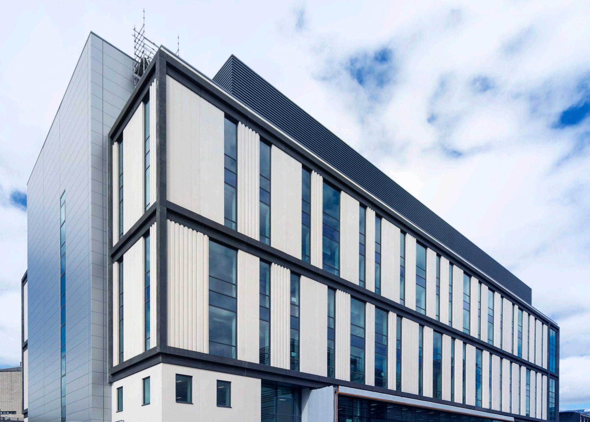
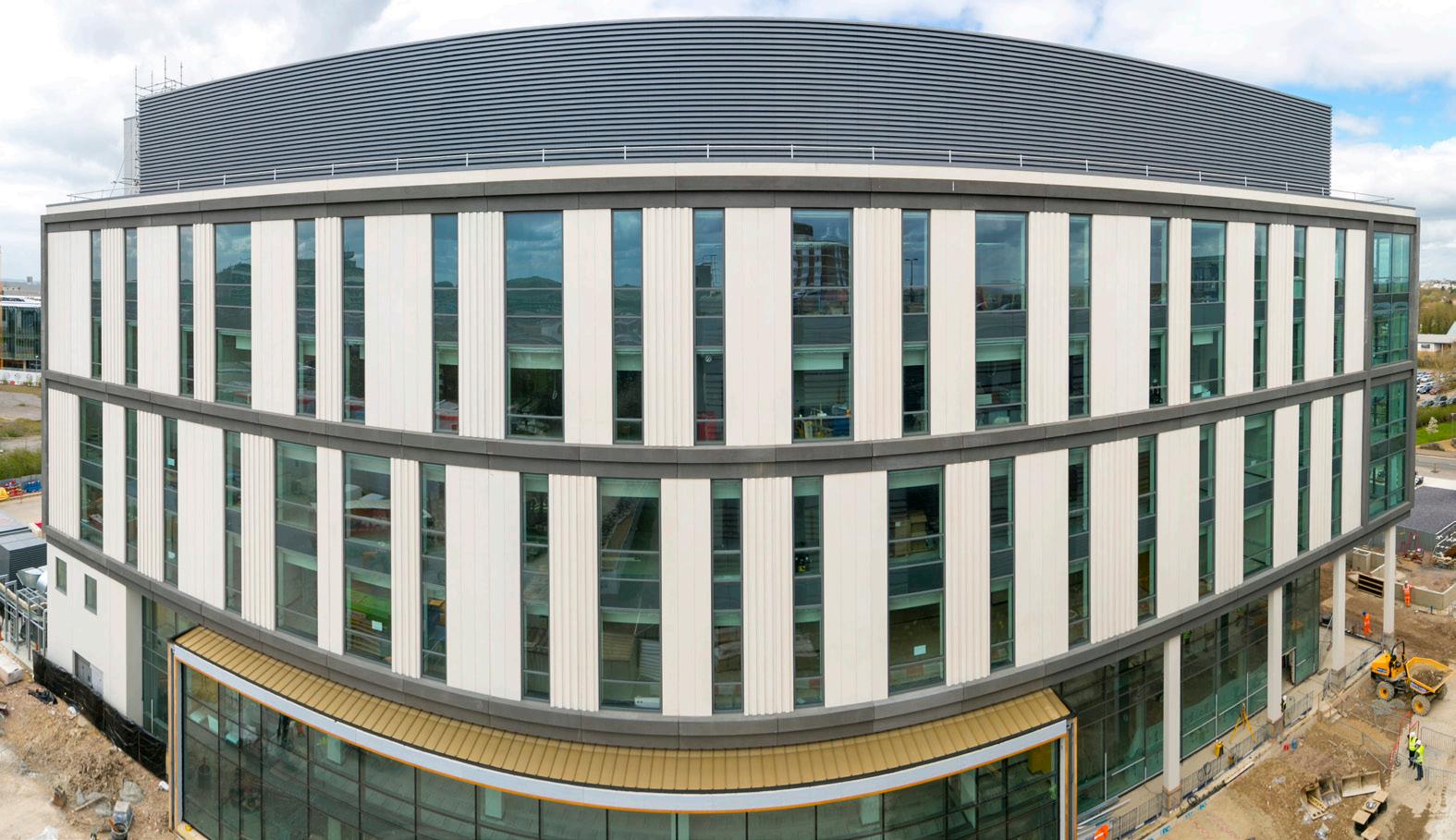
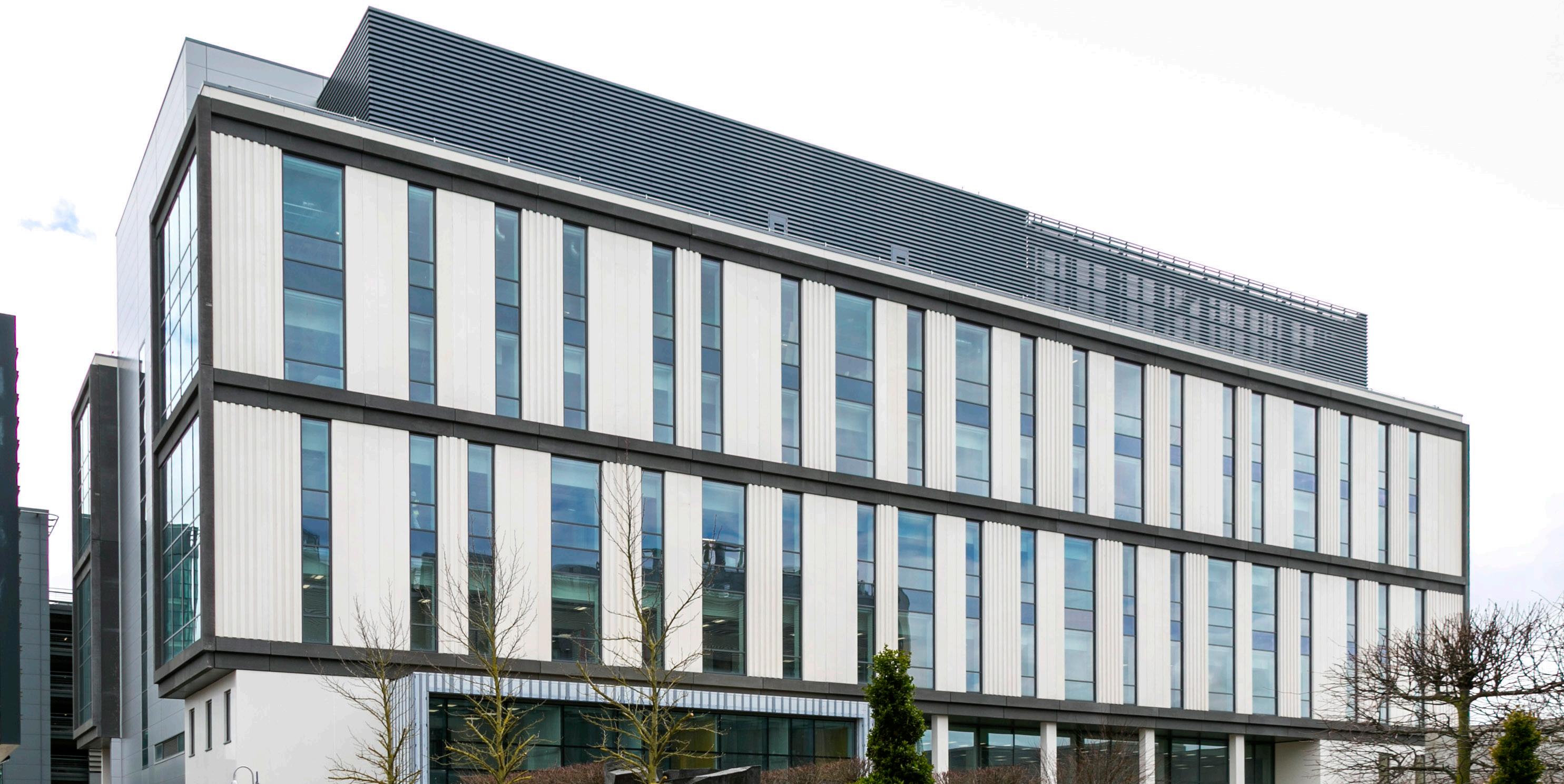
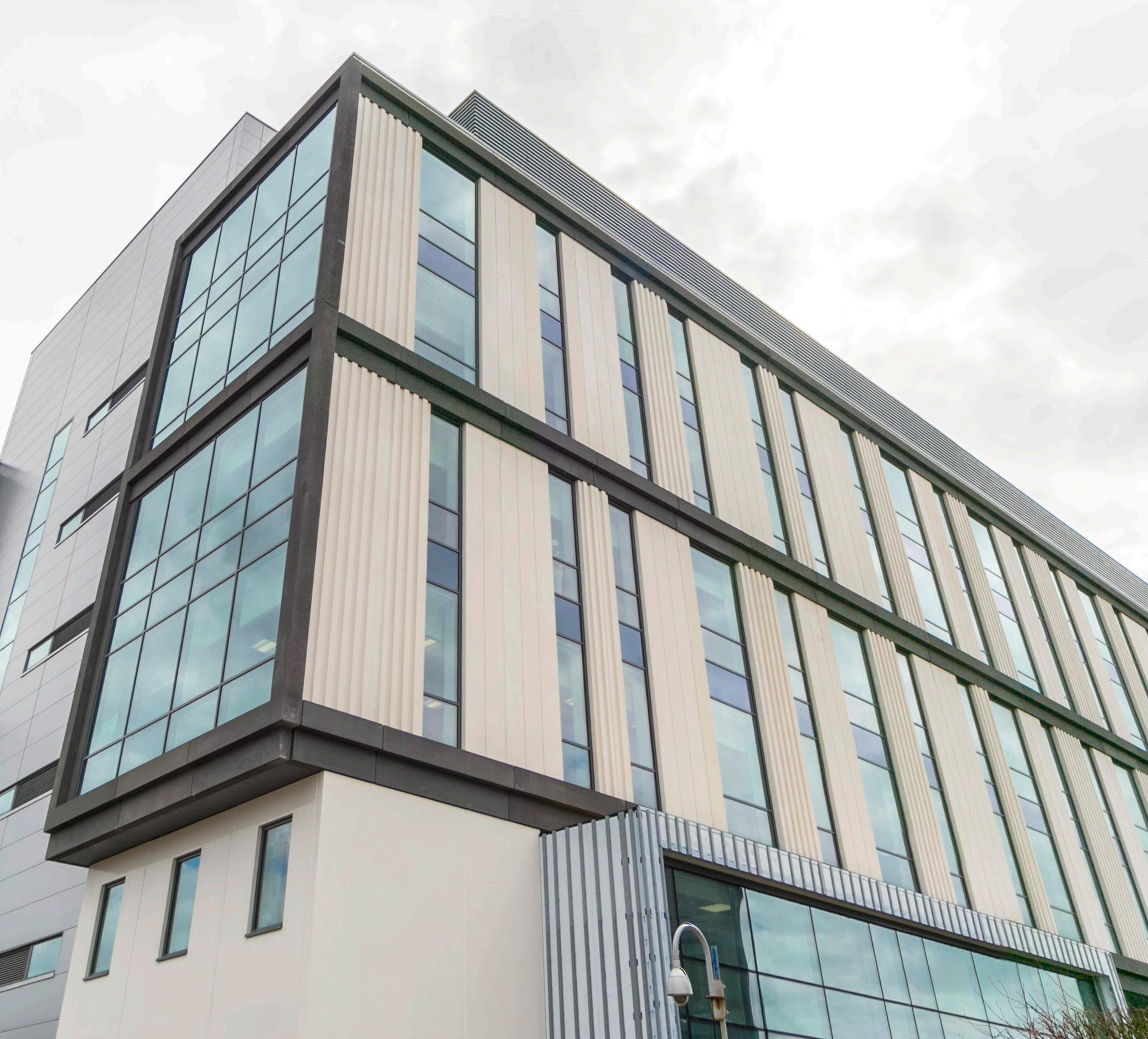
The visually striking façade of the building was constructed of architecturally finished precast concrete cladding panels, columns and beams, with polished surface finishes on those units between ground and second floor, and acid etched surface finishes above. The 4000m² of façade was constructed in just 4 weeks with 8 men and no scaffolding.

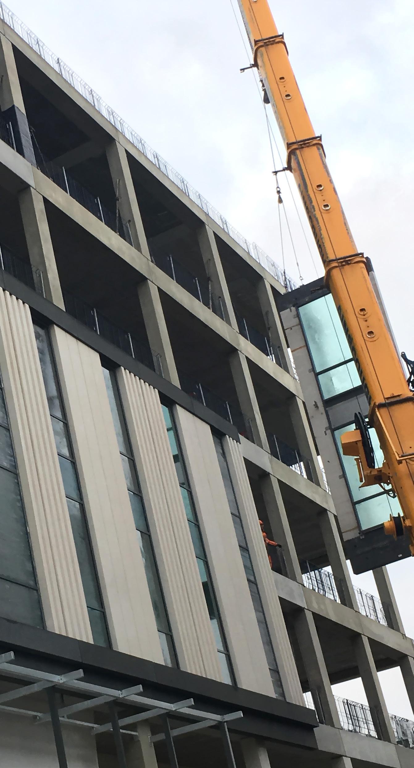
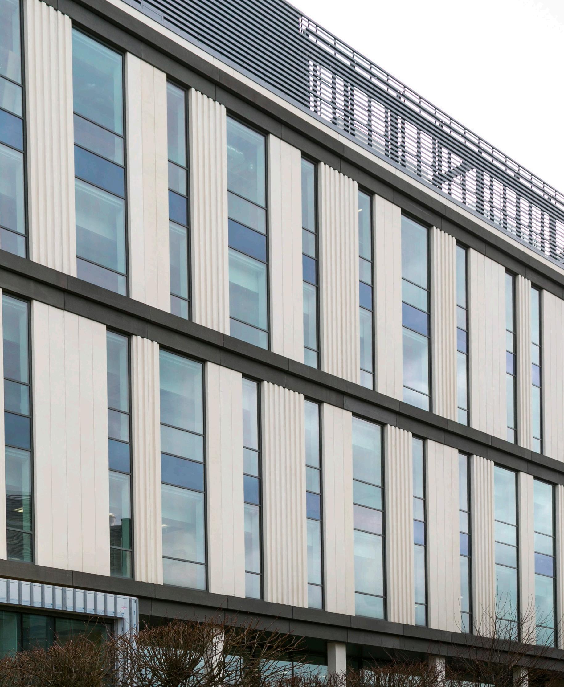

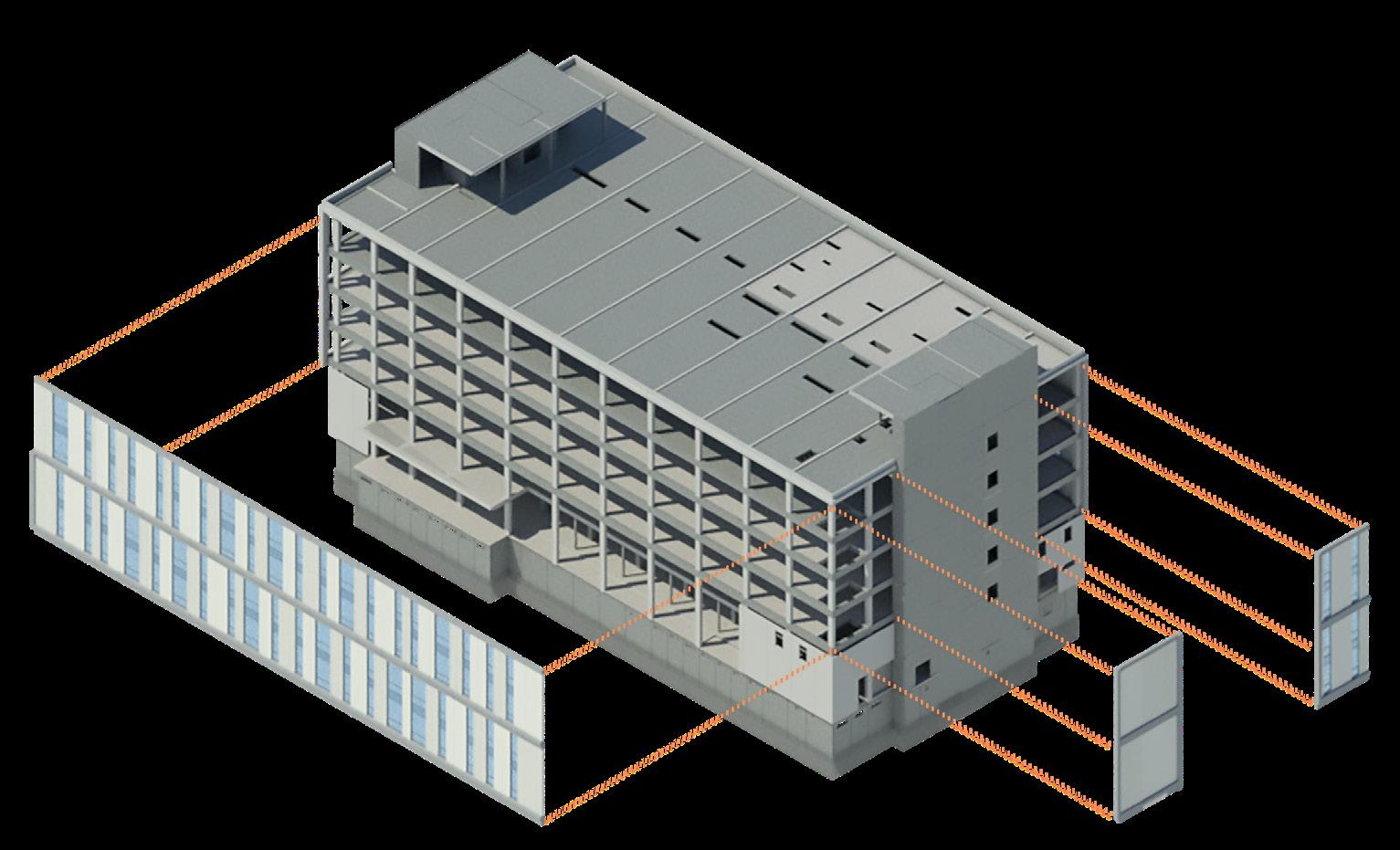
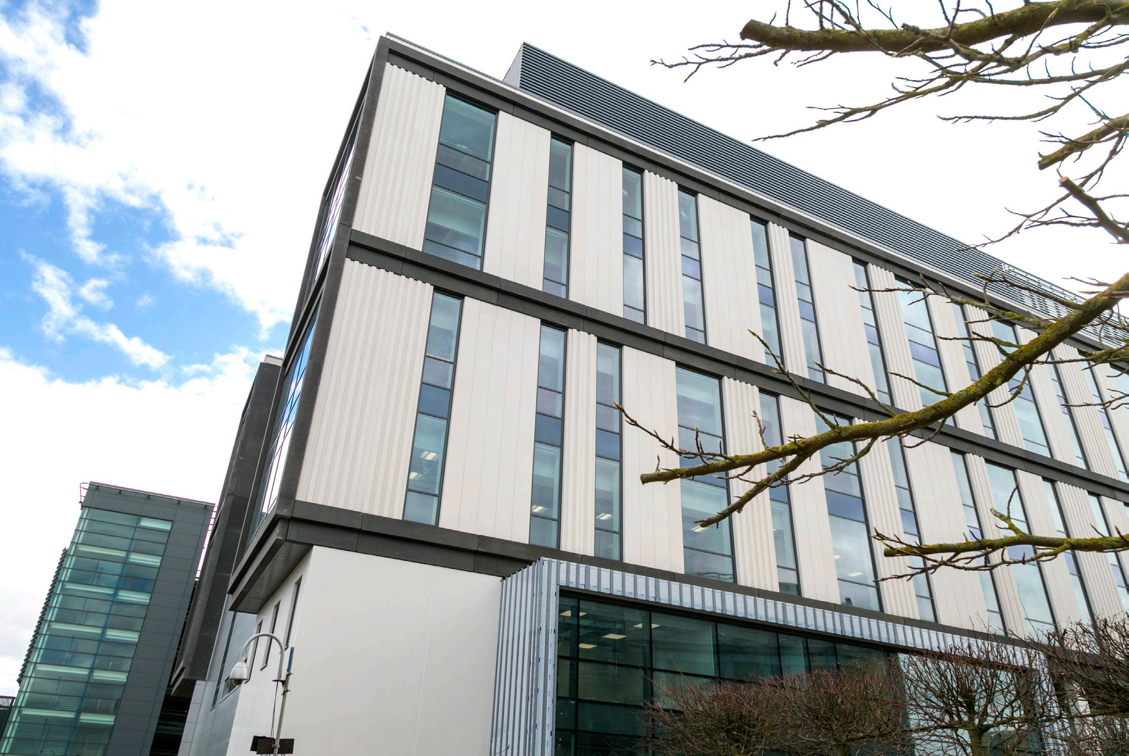
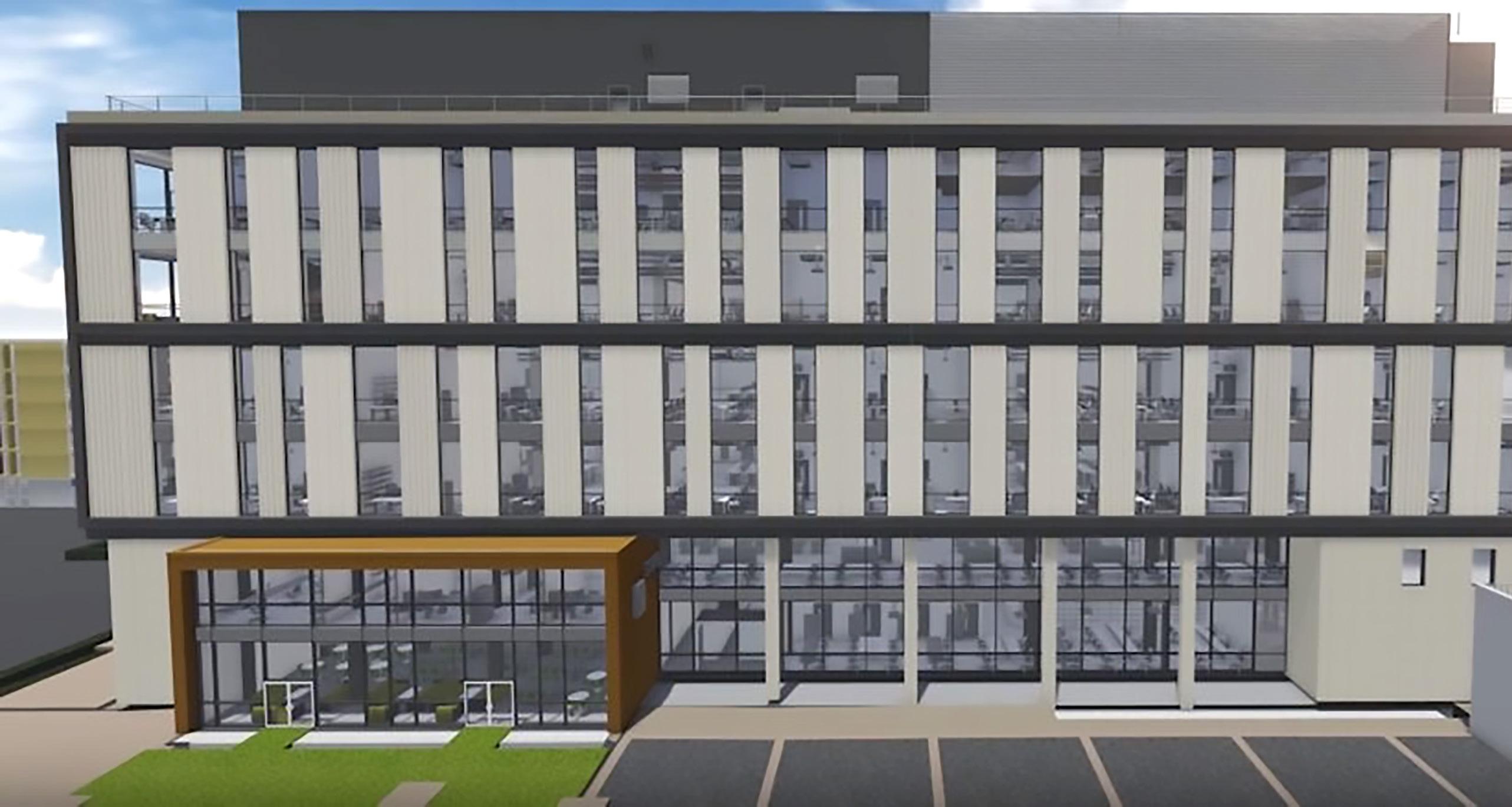
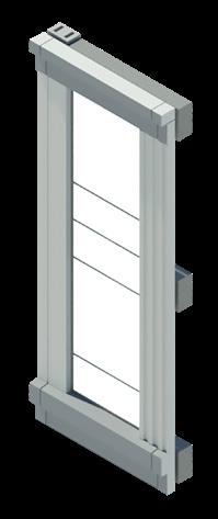
Between floor levels 2-5 the structure is clad in off-site manufactured two-story-height architectural white concrete panels set between black pigmented concrete headers and cills. The two storey height panels were pre-glazed at the production factory before delivery to site. In total, 138 architectural precast cladding panels were delivered and a further 55 architecturally finished precast concrete beams and columns. 120m2 of the façade was successfully erected every working crane day after being turned from their delivery position, without any damage occurring to any of the components.

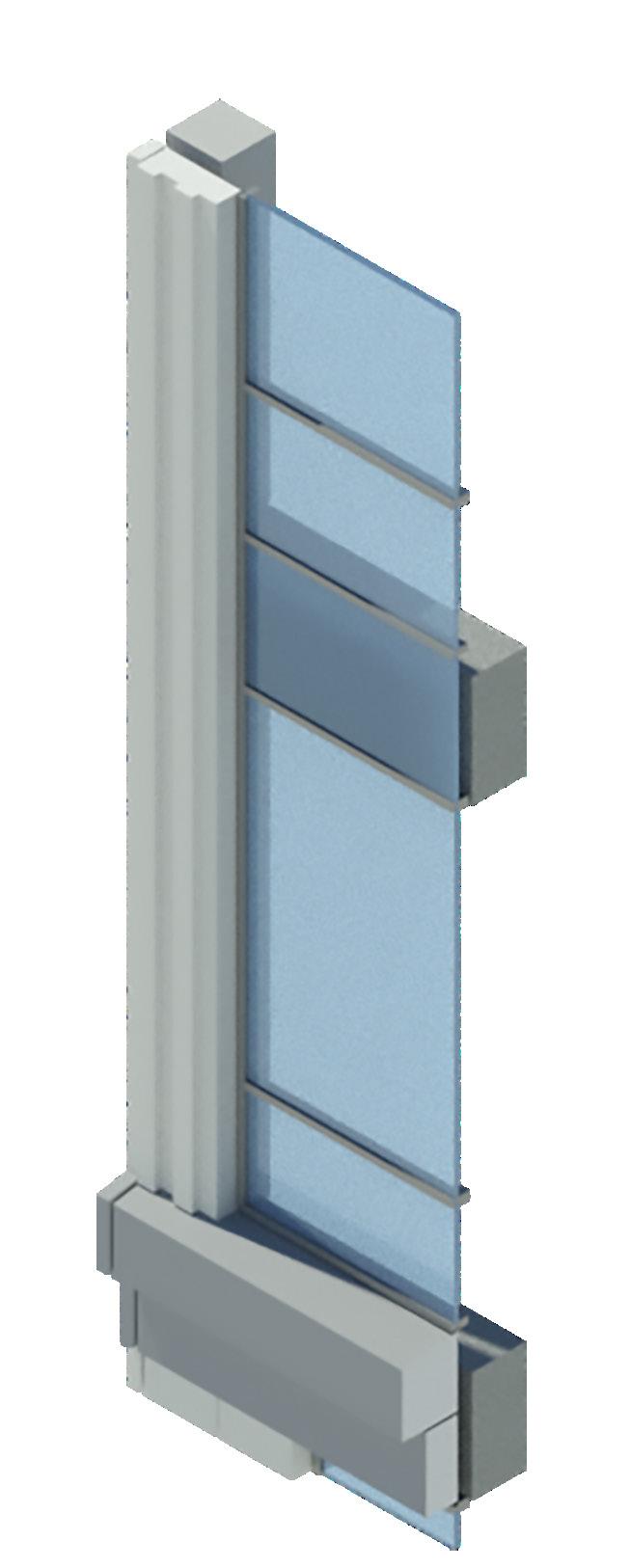
Glazing
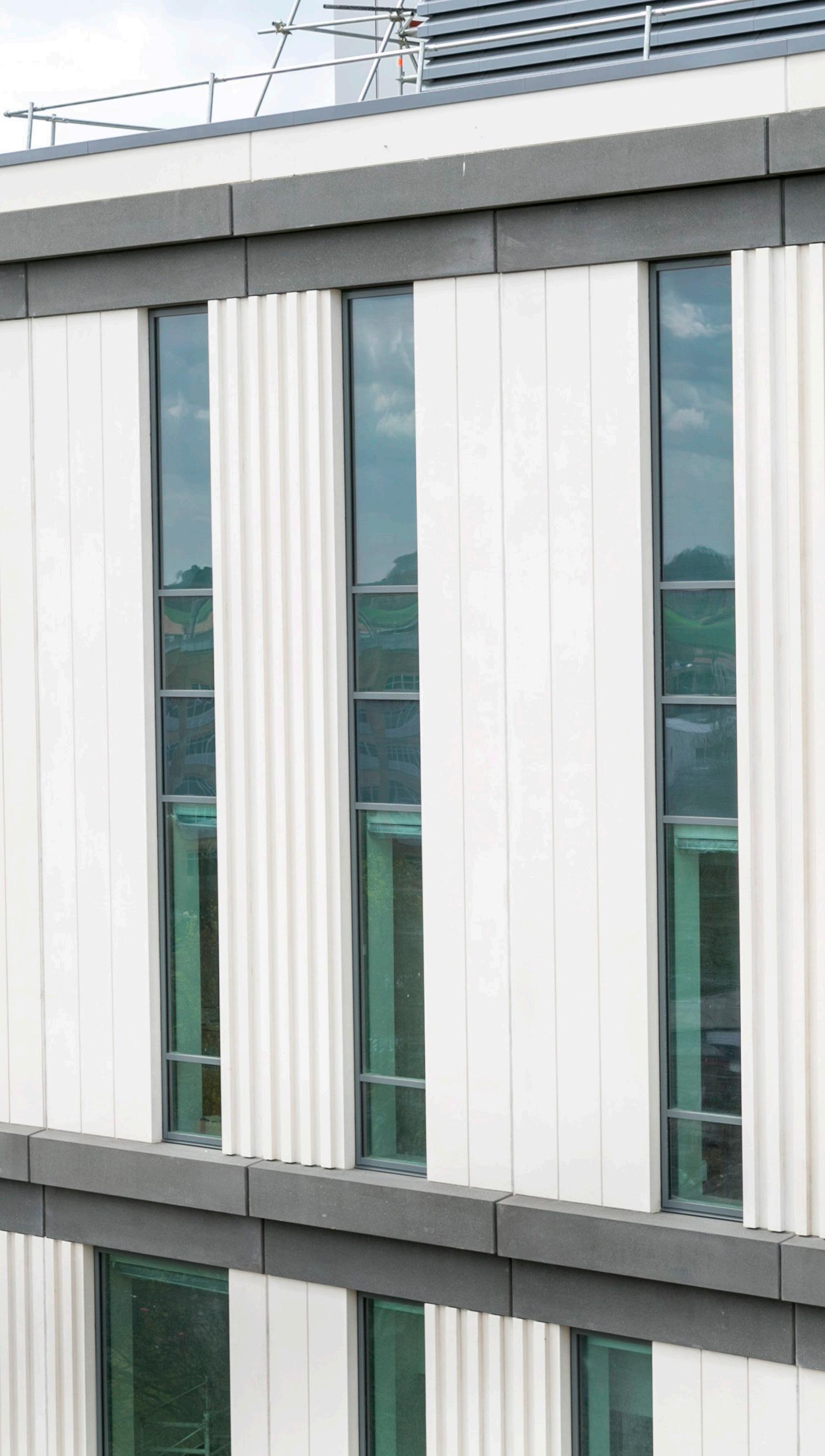
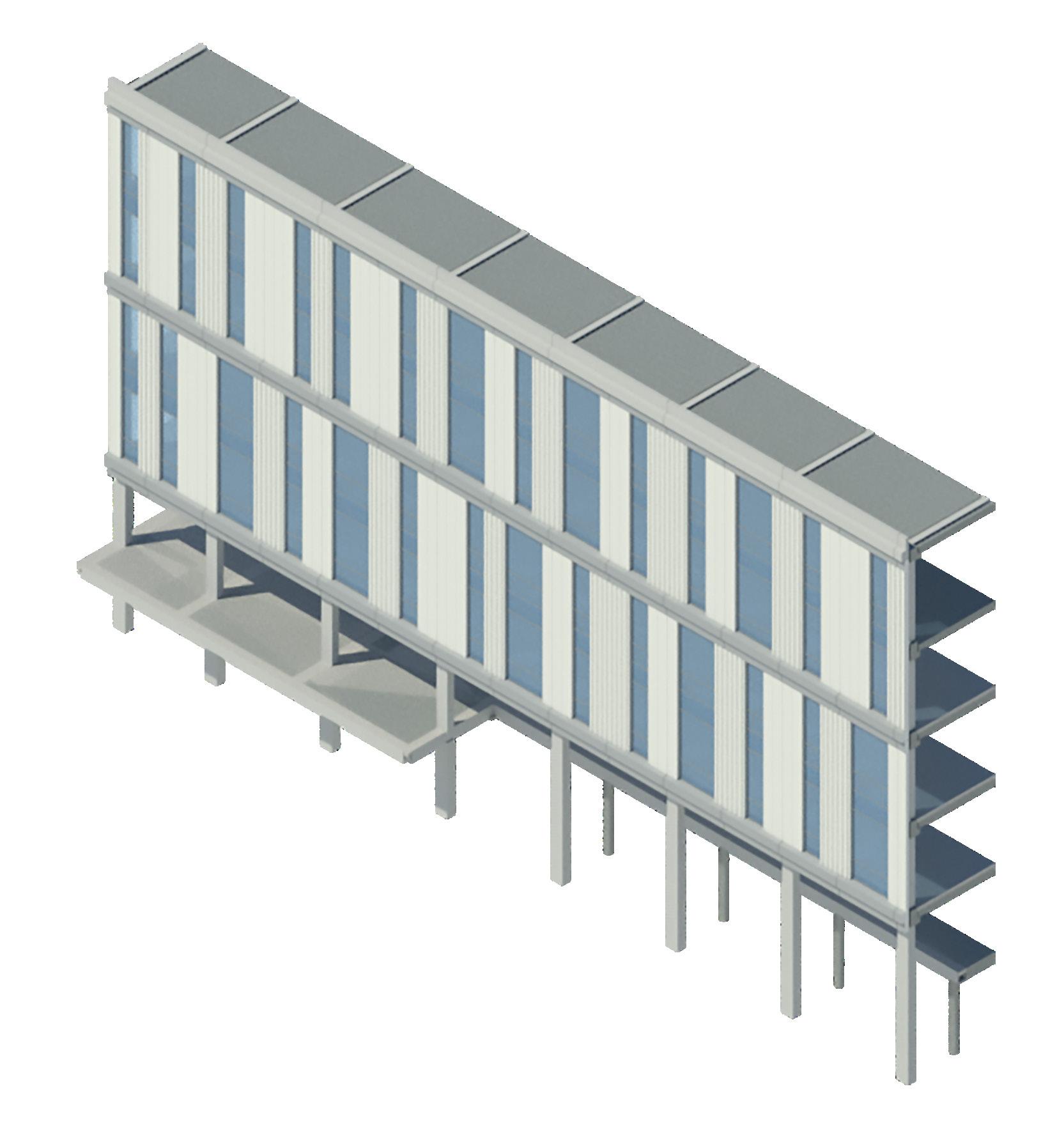 Ribbed Panel
Concrete Panel
Edge Beam
Polished Structural Column

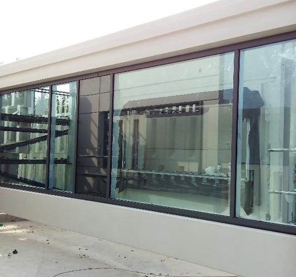

The off-site manufactured cladding units, each measuring 9.5 x 3.3m and weighing 9 tonnes, were transported to site on their long edge and thus required to be offloaded and turned to their vertical aspect for incorporation onto the structural frame. Special lifting and turning mechanisms were developed to facilitate this safety with a series of rigorous trials at the factory to establish the viability of the process prior to the first unit being delivered.

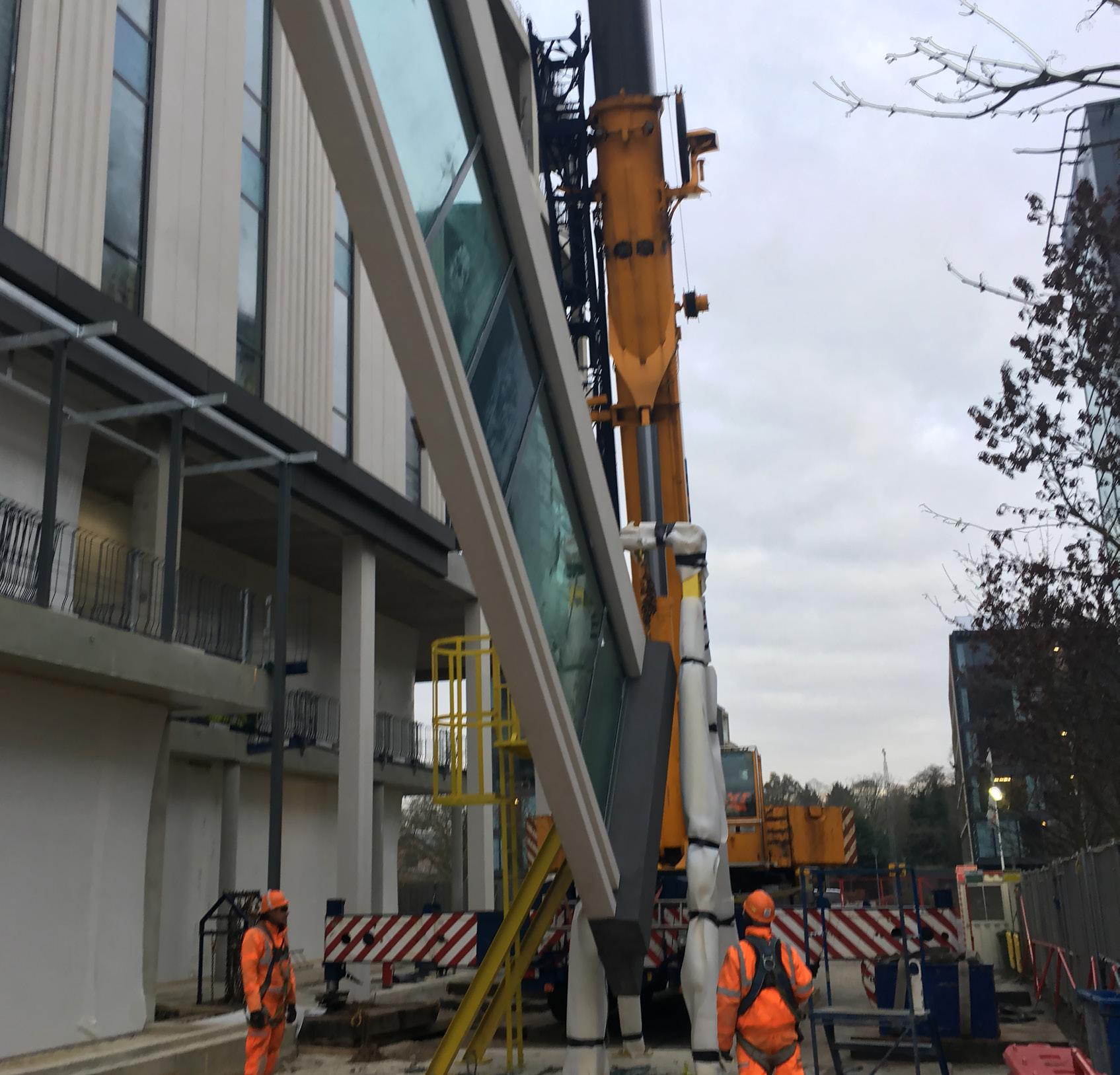
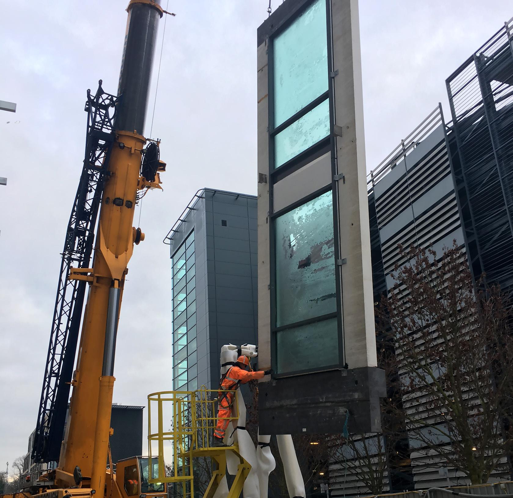


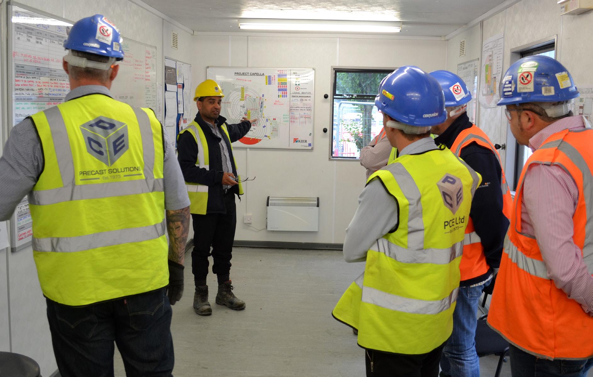
As with all PCE projects, health and safety is at the top of the agenda for critical performance. Risks to the workforce, in the factories and on site, are negated during the design and project planning processes.
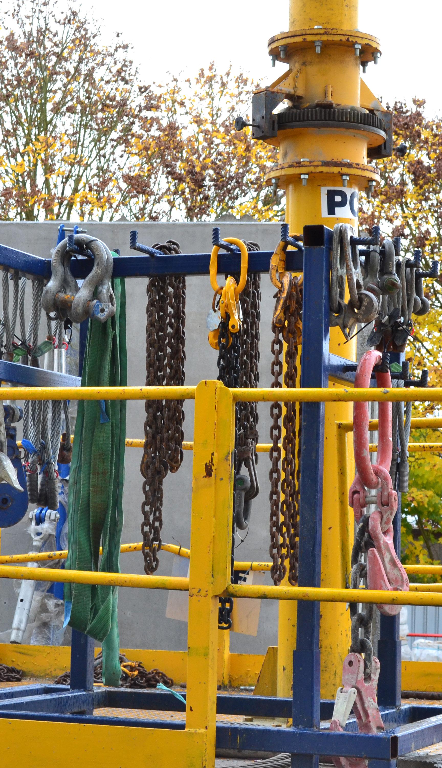
On site, PCE used their in-house developed innovation, SlingSafe, to enable safe offloading of components from flat bed trailers.
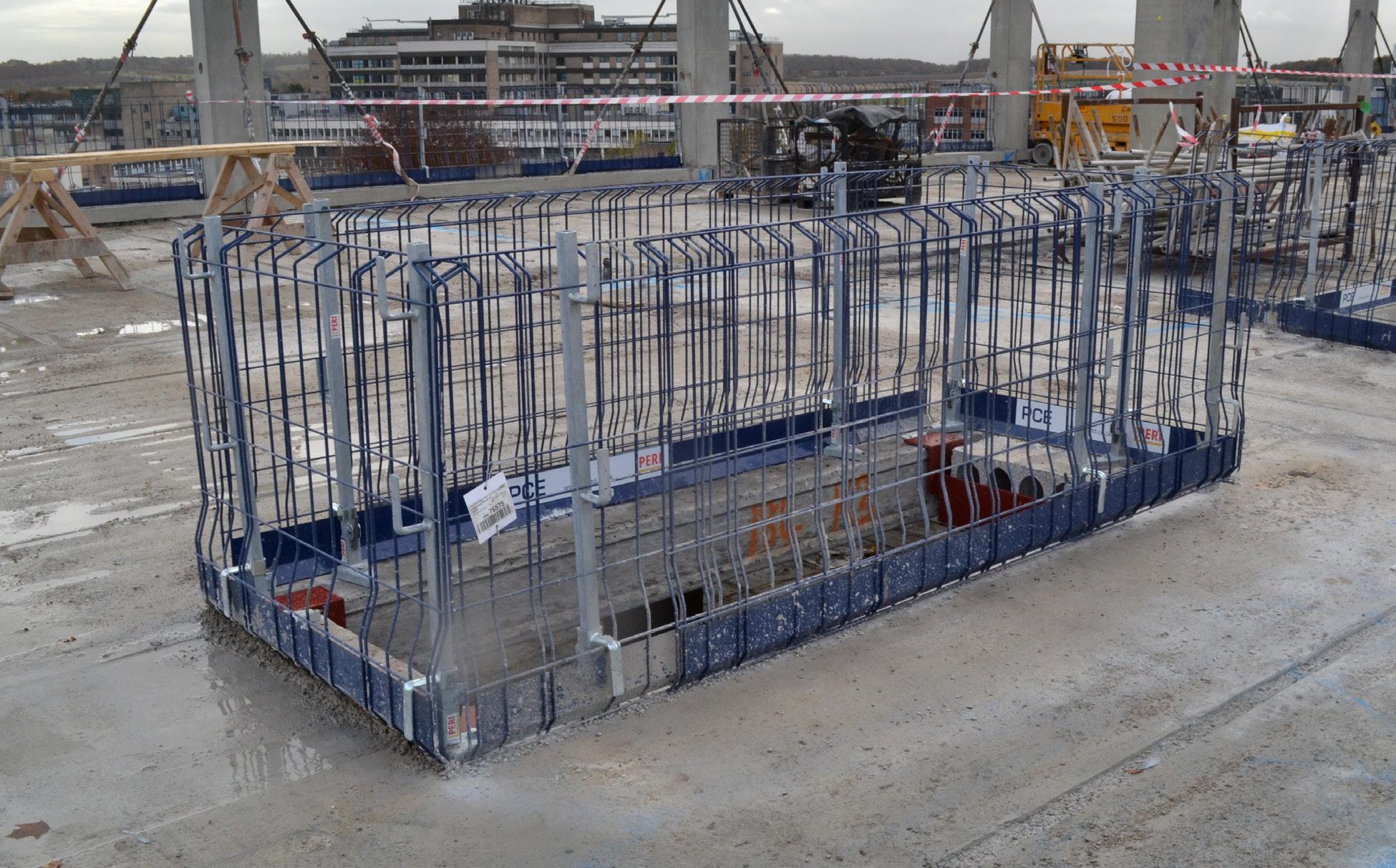
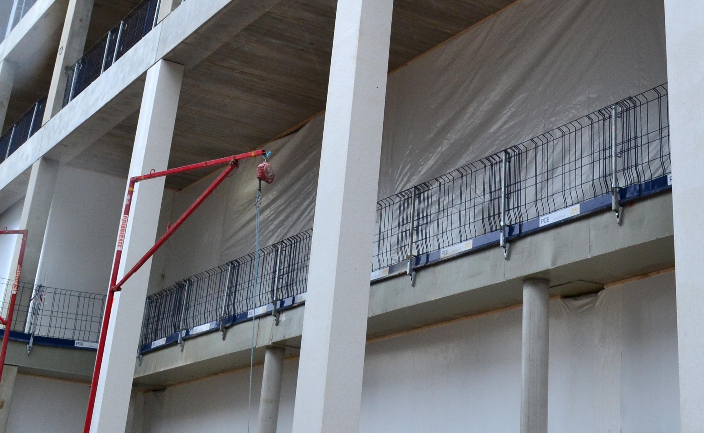
The use of PERI safety rail leading edge system was also used.




15 Days
180 Days
117 Days

48 Days
71 Days
105 Days
90 Days


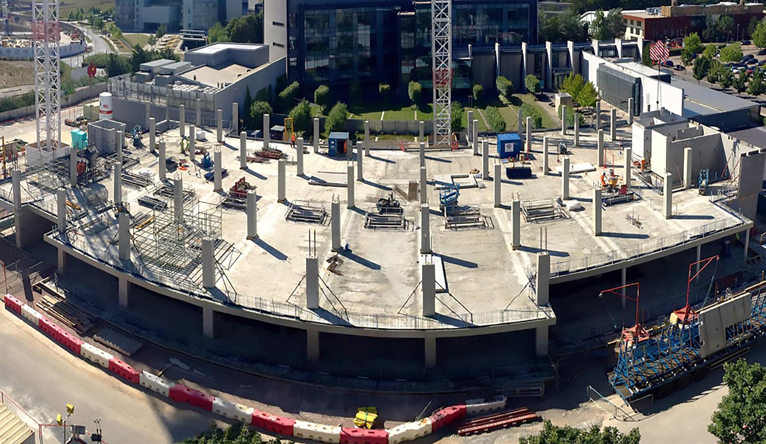

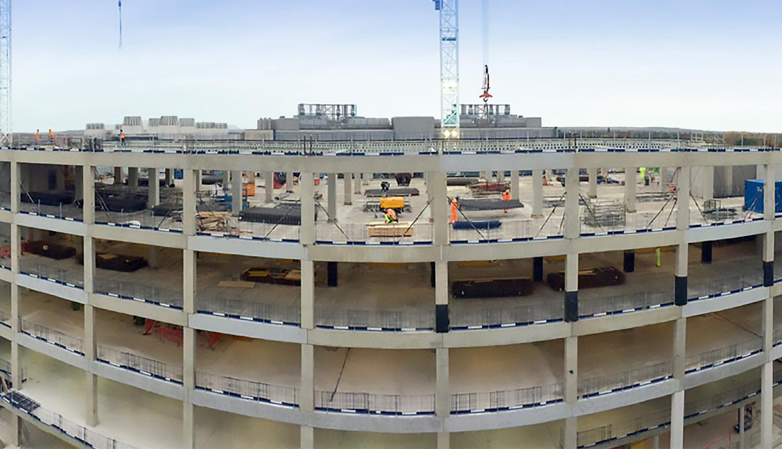
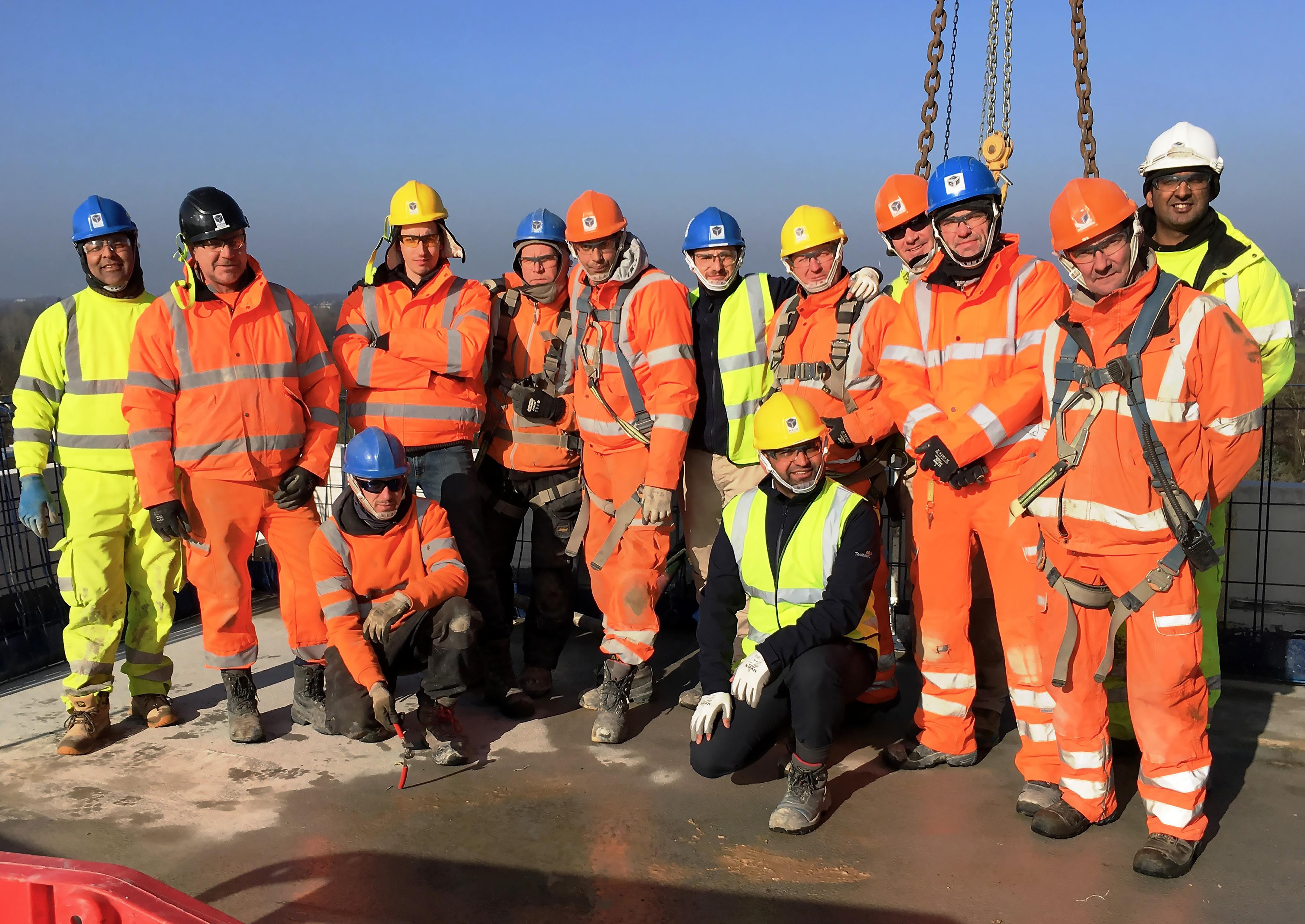
Those members of the PCE Team responsible for the design process focussed on the overall structural stability of the building and its low vibration characteristics, whilst maintaining practicality, repetition, robustness of detailing and efficiency to enable the structural components to be easily manufactured offsite with safe onsite assembly.
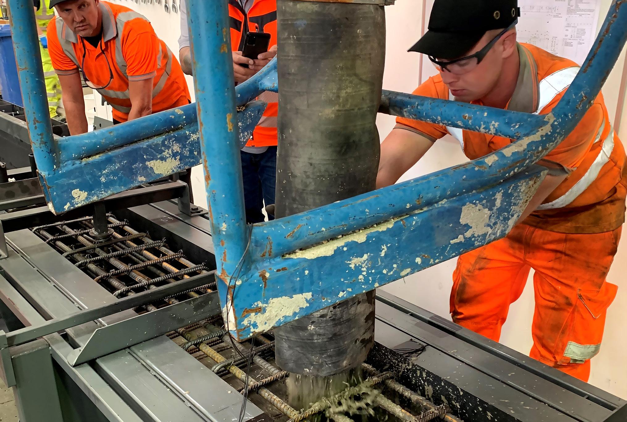
The manufacturing processes were well controlled throughout all of the factories by PCE’s highly trained Quality management staff using the Company’s quality assurance and checking procedures to ensure that all product on arriving at site would fit perfectly where it had been designed for without any remedial works required. Access to the factories was also co-ordinated to enable the windows to be pre-installed into the reconstructed stone cladding panels
Assembly of the offsite manufactured units and the onsite insitu concrete works required was completed by an average number of just 16 of PCE’s multiskilled operatives over a period of only 36 weeks. The structural frame and facades were completed from basement level in just under 28,000 man hours, and most importantly, with no reportable incidents.
To ensure maximum safety and minimal disturbance to the large numbers of people accessing the adjacent neighbouring facilities which included offices, laboratories and a world famous hospital, the logistics surrounding all of the necessary vehicle deliveries were carefully digitally planned and managed from the initial design stages through to onsite completion.
For this project, the construction carbon footprint reduction achieved by off-site factory production is further enhanced by the onsite savings in personnel and deliveries and coupled with reduction in waste disposal gives the HybriDfMA Frames solution a major environmental benefit compared to full on-site construction processes.

Kier estimated that there was a reduction of over 500 lorry deliveries to the site due to the System being used, and an overall reduction in dead weight of the structure more than 3,000 tonnes of reinforced concrete compared to the initial in situ concrete option.
At its peak the total PCE workforce on-site was only 28 personnel and with start to completion of the assembly taking only eight months a saving of over 2,500 site operative weeks resulted when compared to an equivalent in situ concrete solution.

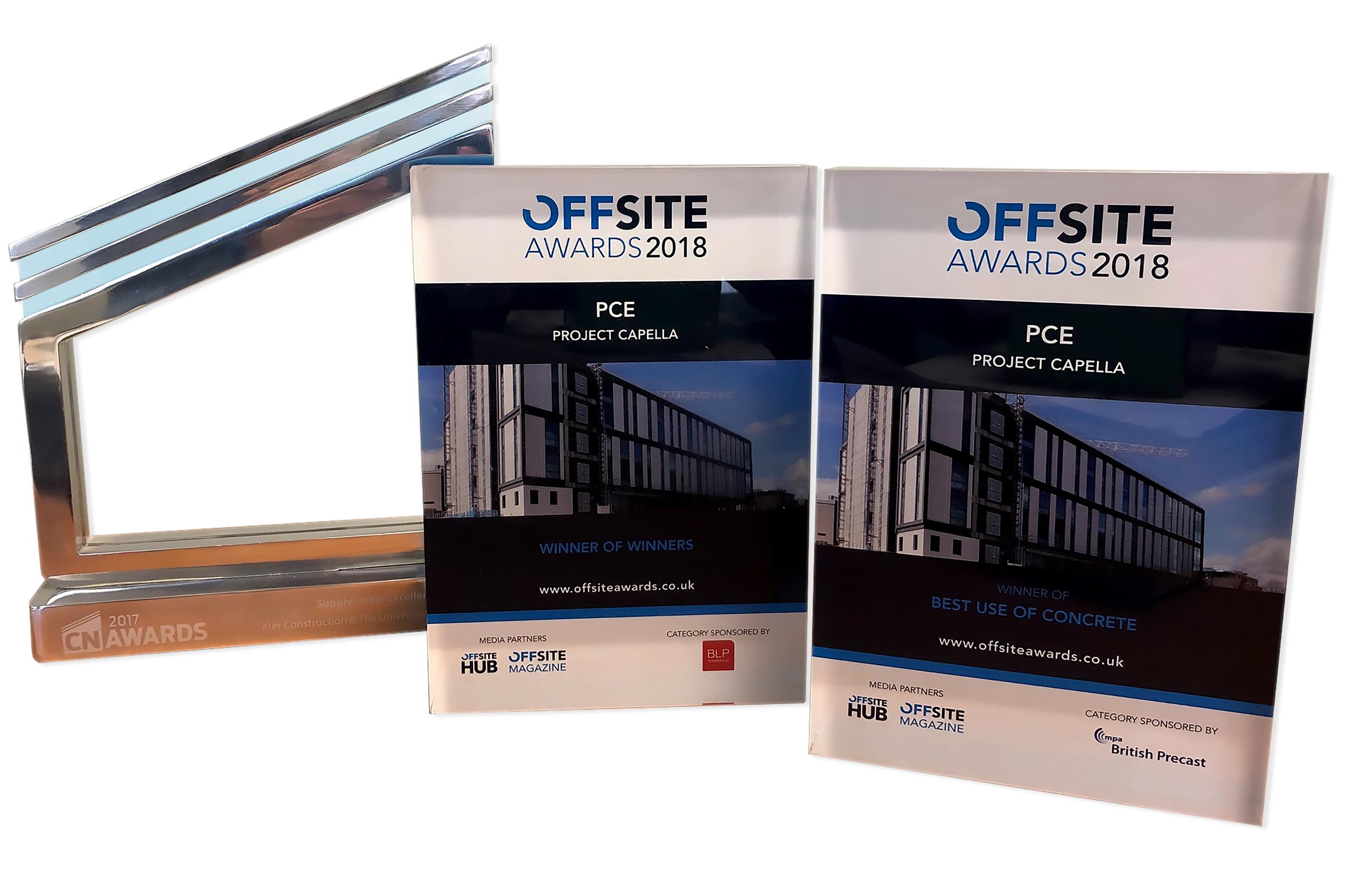
The prestigious ‘Winner of Winners’ the highest scoring entry across presented to PCE for Project Capella. up the award for Best Use of Concrete this project. Adopting a conventional have resulted in significant pressures locate resources. Through the solution, PCE was able to de-risk phase of the project whilst providing the client.
Despite the complexities of the in Cambridge, a combination of implementation and the utilisation manufactured precast components structural package to be delivered This success continues the highly relationship PCE has with Kier
Winners’ Award, given for across all categories was Capella. PCE also picked Concrete Technology for conventional approach would pressures on the site and development of a hybrid de-risk the construction providing cost certainty to the Capella project of effective BIM utilisation of offsite components enabled the delivered in only eight months. highly effective working Kier Group.
